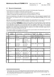
Einbauanweisung
Einbauanweisung
Einbauanweisung

Create successful ePaper yourself
Turn your PDF publications into a flip-book with our unique Google optimized e-Paper software.
F & D<br />
LBA.NSD.005<br />
Inhaltsverzeichnis<br />
<strong>Einbauanweisung</strong><br />
Propeller 10AP-F für Baureihe S10-V<br />
Dokumentnummer:<br />
A34-10-067<br />
Änd.-Index: 01.a<br />
Seite: 1 von 10<br />
Inhaltsverzeichnis 1<br />
1 Allgemeines 1<br />
2 Materialien, Werkzeuge, Unterlagen, Maßnahmen 3<br />
3 Ümrüstung der Baureihe S10 mit Normalpropeller 10AP-N auf Baureihe S10-V mit<br />
Festpropeller 10AP-F 4<br />
4 Ümrüstung der Baureihe S10-V mit Verstellpropeller 10AP-V auf Baureihe S10-V mit<br />
Festpropeller 10AP-F 6<br />
Anhang A: Schaltplan für Umrüstung Motorschalter 8<br />
Anhang B: Fotos 9<br />
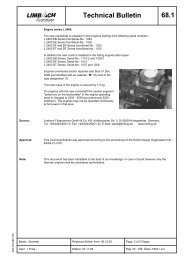
1 Allgemeines<br />
Diese <strong>Einbauanweisung</strong> beschreibt diejenigen Maßnahmen, welche in Verbindung mit der Ausrüstung von<br />
Motorseglern der Baureihe S10-V mit dem Festpropeller 10AP-F als Alternative zum standardmäßigen,<br />
elektrischen Verstellpropeller 10AP-V durchzuführen sind. Sie steht in enger Verbindung zur<br />
� TM A31-10-010 „Wandlung der Baureihe S10 in Baureihe S10-V“, sowie zur<br />
� TM A31-10-067 „Propeller 10AP-F für Baureihe S10-V“.<br />
Der Umfang der Arbeiten, welche in Verbindung mit der Montage des Festpropellers 10AP-F durchzuführen<br />
sind, hängt stark vom aktuellen Bauzustand des Motorseglers ab, an welchem der Propeller installiert<br />
werden soll. Mögliche Ausgangslagen für den Bauzustand sind:<br />
� 1. Baureihe S10 mit Normalpropeller 10AP-N:<br />
Solche Motorsegler können bei gleichzeitiger Durchführung der TM A31-10-010 und der TM A31-10-<br />
067 direkt in eine S10-V mit Festpropeller 10AP-F gewandelt werden.<br />
Anmerkung: Eine spätere Umrüstung auf Verstellpropeller 10AP-V ist ebenfalls möglich. Wurde<br />
anläßlich der Wandlung bereist die Verstellpropeller-Elektrik montiert (TM A31-10-010,<br />
Maßnahme A), so kann die Umrüstung wahlweise beim Hersteller oder bei einem<br />
qualifizierten LTB erfolgen. Wurde die Verstellpropeller-Elektrik nicht montiert (TM<br />
A31-10-010, Maßnahme B), so kann die Umrüstung auf Verstellpropeller ausschließlich<br />
beim Hersteller erfolgen.<br />
� 2. Baureihe S10-V mit Verstellpropeller 10AP-V:<br />
Solche Motorsegler können durch TM A31-10-067 auf den Festpropeller 10AP-F umgerüstet werden.<br />
Diese Arbeiten können entweder beim Hersteller oder durch einen qualifizierten LTB erfolgen.<br />
erstellt: Kurzzeichen MPL geprüft: Kurzzeichen Datum: Ersetzt Ausg. vom LBA anerkannt Datum:<br />
prepared by: Signed<br />
checked by<br />
airworthiness dpt.:<br />
Signed Date:<br />
Supersedes<br />
issue of:<br />
LBA approved Date:<br />
Dalldorff Ellwanger 11.09.2003 --.--.---- ------ ------<br />
A3410067_01a.doc / 07.01.11 12:36
F & D<br />
LBA.NSD.005<br />
A3410067_01a.doc / 07.01.11 12:36<br />
<strong>Einbauanweisung</strong><br />
Propeller 10AP-F für Baureihe S10-V<br />
Dokumentnummer:<br />
A34-10-067<br />
Änd.-Index: 01.a<br />
Seite: 2 von 10<br />
Das folgende Diagramm gibt Aufschluß über die Wandlungsmöglichkeiten zwischen den unterschiedlichen<br />
Bauzuständen sowie über die wichtigsten damit verbundenen Dokumente (Technische Mitteilungen, Einbau-<br />
und Prüfanweisungen):<br />
Baureihe S10 Baureihe S10-V<br />
Durchführung TM A31-10-010 B<br />
Durchführung TM A31-10-067<br />
<strong>Einbauanweisung</strong> A34-10-067<br />
Hersteller oder LTB<br />
STEMME S10-V<br />
Festpropeller 10AP-F<br />
(ohne VP-Elektrik)<br />
Streichung TM A31-10-010 B<br />
Streichung TM A31-10-067<br />
Durchführung TM A31-10-010 A<br />
Prüfanweisung A17-14<br />
nur beim Hersteller<br />
STEMME S10 Duchführung TM A31-10-010 A<br />
STEMME S10-V<br />
Normalpropeller 10AP-N Prüfanweisung A17-14<br />
nur beim Hersteller<br />
Verstellpropeller 10AP-V<br />
(mit VP-Elektrik)<br />
Durchführung TM A31-10-010 A<br />
Durchführung TM A31-10-067<br />
<strong>Einbauanweisung</strong> A34-10-067<br />
Prüfanweisung A17-14<br />
nur beim Hersteller<br />
Durchführung TM A31-10-067<br />
<strong>Einbauanweisung</strong> A34-10-067<br />
Hersteller oder LTB<br />
STEMME S10-V<br />
Festpropeller 10AP-F<br />
(mit VP-Elektrik)<br />
Streichung TM A31-10-067<br />
Prüfanweisung A17-14<br />
Hersteller oder LTB<br />
Eine Ausrüstung mit Festpropeller 10AP-F kann grundsätzlich wahlweise beim Hersteller oder ggf. auch bei<br />
einem qualifizierten LTB erfolgen. Die zugehörigen Arbeitsschritte werden in dieser <strong>Einbauanweisung</strong><br />
ausführlich beschrieben.<br />
Eine erstmalige Ausrüstung der STEMME S10 mit Verstellpropeller 10AP-V und den zugehörigen<br />
elektrischen Komponenten stellt eine umfangreiche Arbeit dar, welche grundsätzlich nur vom Hersteller<br />
durchgeführt werden kann und wird hier deshalb auch nicht näher betrachtet.<br />
Eine erneute Montage des Verstellpropellers 10AP-V kann wahlweise beim Hersteller oder ggf. auch bei<br />
einem qualifizierten LTB erfolgen, sofern die elektrischen Komponenten des Verstellpropellers bereits<br />
installiert sind (z.B. wenn zwischenzeitlich der Festpropeller 10AP-F montiert war), jedoch wird hier auf eine<br />
solche erneute Ausrüstung mit Verstellpropeller 10AP-V ebenfalls nicht näher eingegangen. Bei Bedarf kann<br />
jedoch ein entsprechender Dokumentensatz bei STEMME angefordert werden. Er beinhaltet die<br />
notwendigen Unterlagen wie die Montagezeichnung A12-10AP-V, die Stückliste A21-10AP-V, die<br />
Prüfanweisung A17-14, Auszüge aus der Verfahrensanweisung 10AP-V/1 „Montage Propeller 10AP-V“<br />
(Kap. 2.18 bis 2.21), die VA A17-10AP-V/2 „dynamisches Auswuchten“ und die zugehörigen Prüfprotokolle<br />
(VP-Einstellbericht , dyn. Auswuchtbericht, Standlaufbericht, Wägebericht, Flugbericht).
F & D<br />
LBA.NSD.005<br />
<strong>Einbauanweisung</strong><br />
Propeller 10AP-F für Baureihe S10-V<br />
2 Materialien, Werkzeuge, Unterlagen, Maßnahmen<br />
A3410067_01a.doc / 07.01.11 12:36<br />
Dokumentnummer:<br />
A34-10-067<br />
Änd.-Index: 01.a<br />
Seite: 3 von 10<br />
Materialien: bei Umbau von: S10 S10-V<br />
Teile.Nr. Anz. Bezeichnung (10AP-N) (10AP-V)<br />
10AP-F 1 Propeller 10AP-F X X<br />
10AP-NS 6 Schraube 10AP-NS X X<br />
D125-08 6 Scheibe D125-08 X<br />
10AP-V66 1 Distanzring 10AP-V66 X<br />
10AP-V67 1 Distanzring 10AP-V67 X<br />
10AM-K 1 Set mit vormontiertem Kühlluftklappen-Betätigungshebelebel X<br />
10AA-23 4 Glockenelement 65 shore X<br />
10A-28 4 Buchse X<br />
1 Zweites Typenschild mit neuer Baureihe und Werk-Nr. bei Wandlund S10 ==> S10-V X<br />
1 Satz Beschilderungen für Baureihe S10-V X<br />
1 Elektrik-Nachrüstset mit vormontiertem Domschalter X<br />
0,6m Sicherungsdraht L9424-1,0 für Propellerschrauben 10AP-NS X X<br />
1 Satz Kleinmaterialien:<br />
Stopmuttern, Scheiben, Loctite, Schrumpfschlauch, Isolierband, Kabelbinder, etc. X X<br />
2 Blindstopfen für Bohrung 13mm X<br />
1 Blindstopfen für Bohrung 8mm X<br />
Werkzeuge: bei Umbau von: S10 S10-V<br />
Bezeichnung (10AP-N) (10AP-V)<br />
Mechaniker-Werkzeugsatz, metrisch X X<br />
Heissluftpistole X X<br />
Zange für Sicherungsdraht X X<br />
Drehmomentenschlüssel (bis ca. 50 Nm) X X<br />
Crimpzange X<br />
Abisolierzange X<br />
Unterlagen: bei Umbau von: S10 S10-V<br />
Dok.-Nr. Ind. Bezeichnung (10AP-N) (10AP-V)<br />
A-34-10-067 01.a <strong>Einbauanweisung</strong> "Propeller 10AP-F für Baureihe S10-V" (vorliegendes Dokument) X X<br />
A40-10-110 5 Flughandbuch S10-V (Ber. 5 oder höher) incl. Alternativseiten für Propeller 10AP-F X X<br />
A40-10-120 11 Wartungshandbuch S10-V (Berichtigung 11 oder höher) X X<br />
A35-10-067 01.a Wartungsanweisung S10-V mit Propeller 10AP-F X X<br />
A12-10AA 21.a Zusammanbauzeichnung Getriebeaufhängung S10 / S10-V X<br />
A21-14AA 01.a Stückliste Getriebeaufhängung S10-V X<br />
A12-10AM-K 13.b Zusammenbauzeichnung Kühlluftklappen-Betätigung S10 / S10-V X<br />
A20-10AM-K-E 13.d Stückliste Kühlluftklappen-Betätigung X<br />
A12-10AG-00-01 20.a Zusammenbauzeichnung Getriebe, komplett X<br />
A12-10AP-F-01 01.b Zusammenbauzeichnung Propeller 10AP-F X X<br />
A12-10AP-F-02 01.a Zusammenbauzeichnung Propeller 10AP-F X X<br />
A21-10AP-F 01.a Stückliste Propeller 10AP-F X X<br />
A31-10-001 09.a TM "Übersicht über zulässige Betriebszeiten" (Ausgabe 09.a oder höher) X X<br />
A31-10-010 02.a TM "Wandlung der Baureihe S10 in Baureihe S10-V" X<br />
A31-10-067 01.a TM "Propeller 10AP-F für Baureihe S10-V" X X<br />
1001-10-a A Bodenlauprotokoll Motorsegler STEMME S10, Baureihe: S10 und S10-V X X<br />
1001-04-c A Flugbericht STEMME S10 und Baureihen X X<br />
1001-12-a B Gewichtsübersicht STEMME S10, S10-V X X<br />
JAA Form One für Propeller 10AP-F X X<br />
LBA-Kennblatt Nr. 846 für STEMME S10-V, Ausgabe 5 oder höher X X<br />
Maßnahmen: bei Umbau von: S10 S10-V<br />
lfd. Nr: Beschreibung (10AP-N) (10AP-V)<br />
1 Umsetzung der Propellerbremstrommel um 90° X<br />
2 Einbau von Shock-Mounts nach anderer Spezifikation X<br />
3 Montage des Festpropellers 10AP-F X X<br />
4 Einbau der Kühlluftklappenreduzierung X<br />
5 Stillegung / Ausbau von Komponenten der Verstellpropeller-Elektrik X<br />
6 Einau des Motor-Domschalters (Motorhauptschalter) X<br />
7 Änderungen der Beschilderung in der Kabine und von der Elektrik X X<br />
8 Anbringen des 2. Typenschildes mit neuer Baureihenkennzeichnung und Werknummer X<br />
9 Änderungen in den Flug- und Wartungshandbüchern incl. WHB-Ergänzung X X<br />
10 Korrektur der Prüfunterlagen (insbesondere Wägebericht und Betriebszeitenübersicht) X X<br />
11 Prüfung und Bescheinigung der Arbeiten X X<br />
12 Bodenlauf und Prüfflug X X
F & D<br />
LBA.NSD.005<br />
A3410067_01a.doc / 07.01.11 12:36<br />
<strong>Einbauanweisung</strong><br />
Propeller 10AP-F für Baureihe S10-V<br />
3 Ümrüstung der Baureihe S10 mit Normalpropeller 10AP-N<br />
auf Baureihe S10-V mit Festpropeller 10AP-F<br />
Dokumentnummer:<br />
A34-10-067<br />
Änd.-Index: 01.a<br />
1 Demontage Propellerdom<br />
1.1 Demontage des Propellerdoms; siehe Wartungshandbuch (WHB)<br />
2 Demontage Normalpropeller 10AP-N<br />
2.1 Demontage des alten Propellers; siehe WHB<br />
3 Demontage Antriebsstrang<br />
3.1 Demontage des Antriebsstrangs; siehe WHB<br />
4 Demontage der Getriebeaufhängung<br />
4.1 Demontage der vier Shock-Mounts vom Rumpfspant; siehe WHB und A12-14AA<br />
5 Modifikation der Getriebeaufhängung<br />
Vorbemerkung:<br />
Alle Arbeiten nach Stückliste A21-14AA sowie Zeichnung A12-10AA mit Einzelheit für Baureihe S10-V<br />
Austausch der Glockenelemente in den vier Shock-mounts von 55shore (Teile-Nr.: 10AA-24, alt) auf<br />
5.1<br />
65shore (Teile-Nr.: 10AA-23, neu)<br />
Austausch der Buchsen der in den Shock-mounts von 40mm lang (Teile-Nr.: 10AA-08, alt) auf 35mm lang<br />
5.2<br />
(Teile-Nr.: 10AA-28, neu, blau lackiert)<br />
6 Umsetzen der Bremstrommel<br />
Um 90° um die Propellerachse herum verdrehte Montage der Bremstrommel 10AG-12 auf der Rückseite der<br />
Propellerwelle des Riemengetriebes 10AG (==> die beiden Nuten für die Propellerpositionierung in der<br />
6.1 Bremstrommel müssen in Richtung der Propellerblätter zeigen). Dazu Bremstrommel von Propellerwelle<br />
demontieren und verdreht wieder montieren, dabei die Scheiben zwischen Bremstrommel und<br />
Riemenscheibe nicht vergessen, d.h. wieder montieren (Zusammenbauzeichnung A12-10AG-00-01).<br />
7 Installation Dom-Motorhauptschalter - Umbau Einschaltkreise, Motorschiene und Starterkreise<br />
Vorbemerkung:<br />
Nachfolgend beschriebene Modifikation dient zur Entfernung des manuellen Kippschalters aus dem<br />
Einschaltkreis der Motorschiene. Die Motorschiene wird dann durch den Propellerdom-Endschalter<br />
eingeschaltet (beim Verriegeln des Dombetätigungshebels). Um den PropDomSchalter für diese Funktion<br />
„freizumachen“ muß der Starterkreis ebenfalls modifiziert werden. Das Anlassen des Motors ist danach nicht<br />
mehr direkt vom PropDomSchalter abhängig. Dennoch kann bei geschlossenem Dom kein versehentliches<br />
Anlassen erfolgen, da die gesamte Motorschien (und damit der Starterkreis) vom PropDomSchalter<br />
eingeschaltet wird.<br />
Es wird der Umbau mit bereits installiertem MotorNotSchalter beschrieben. Bei sehr frühen Seriennummern<br />
kann dieser noch fehlen und muß nachgerüstet werden.<br />
Ein Schaltplan für die beschriebene Umrüstung des Motorhauptschalters ist in Anhang A dieses Dokuments<br />
zu finden.<br />
7.1 Voltmeter, Öldruckanzeige, Drehzahlmesser für bessere Arbeitsfreiheit ausbauen<br />
7.2 Motorschalter ausbauen und Leitungen 002(2x), 12, 70, 71 abklemmen<br />
MotorNotschalter ausbauen und Leitungen 004, 49 abklemmen, Spiralband bis zum Hauptkabelbaum<br />
7.3<br />
abwickeln<br />
7.4 Avionik-Umschalter „Haupt/Zusatzakku“ in die Position des ehemaligen Motorschalters umsetzen<br />
Verlängerung der Leitungen 002 (2x), 12, 70, 71 (ehem. Motorschalter) zum MotorNotSchalter (ca. 20cm)<br />
7.5<br />
und zum PropDomSchalter (ca. 65cm)<br />
7.6 neue Leitung mit Spiralband umwickeln und ordnungsgemäß verlegen<br />
7.7 Fahrwerksicherung, Fahrwerkschalter, Avionikschalter für bessere Arbeitsfreiheit ausbauen<br />
7.8 Leitungen 49 (2x) vom Zündschalter abklemmen, Ringösen abschneiden.<br />
Leitungen 004, 49 vom PropDomSchalter abklemmen, Spiralband bis zum Hauptkabelbaum abwickeln,<br />
7.9 Leitung 49 aus dem Kabelbaum ziehen, Leitung 004 isolieren und hinter der Schalterleiste in den<br />
Kabelbaum einbinden.<br />
7.10 Leitung 004 (ehemals MotorNotSchalter) an Zündschalter anschließen<br />
7.11 ausgebaute Schalter in die Schalterleiste wieder einbauen<br />
ausgebaute Instrumente wieder einbauen, nicht benötigte Öffnungen im Instrumentenbrett mit Blindstopfen<br />
7.12<br />
verschließen<br />
8 Einbau der Kühlluftklapen-Betätigung<br />
Einbau der Kühlluftklappenreduzierung nach Stückliste A20-10AM-K-E, Zeichnung A12-10AM-K sowie Fotos<br />
8.1<br />
im Anhang<br />
9 Montage Getriebeaufhängung<br />
9.1 Montage der vier modifizierten Shock-Mounts am Rumpfspant; siehe Zeichnung A12-10AA<br />
10 Montage Antriebsstrang<br />
10.1 Montage des Antriebsstrangs im Rumpf; siehe WHB<br />
Seite: 4 von 10<br />
Prüfvermerk
F & D<br />
LBA.NSD.005<br />
A3410067_01a.doc / 07.01.11 12:36<br />
<strong>Einbauanweisung</strong><br />
Propeller 10AP-F für Baureihe S10-V<br />
Dokumentnummer:<br />
A34-10-067<br />
Änd.-Index: 01.a<br />
11 Montage des neuen Propeller 10AP-F<br />
Montage des Propellers 10AP-F am Riemengetriebe 10AG nach Zeichnung A12-10AP-F. Dabei sechs neue<br />
11.1 Bolzen 10AP-NS verwenden, dabei die Scheiben D125-08 zwischen Schraubenkopf 10AP-NS und<br />
Zentralteil 10AP-F01 nicht vergessen.<br />
Freigängigkeit prüfen: Sollten die Propellerblätter beim Ein- und Ausfaltvorgang (mit der Hand wiederholt<br />
über eine komplette Propellerumdrehung simulieren) kurz vor Erreichen des voll eingefalteten Zustands mit<br />
11.2<br />
der Blatthinterkante a) entweder an den äußersten Rändern der Tragarme des Getriebeträgers b) oder an<br />
der Rumpfabschlußkante scheuern, so ist ggf. ein Distanzring (10AP-V67 (1,0mm) oder 10AP-V66 (1,5mm))<br />
zwischen Riemenscheibe und Zentralteil 10AP-F01 des neuen Propellers 10AP-F zu montieren. In diesem<br />
Fall muß die Phase der Innenbohrung des Distanzringes zur Riemenscheibe zeigen.<br />
11.3<br />
Anziehen der Schauben 10AP-NS laut WHB: erst mit 10Nm über Kreuz, dann mit 30Nm über Kreuz,<br />
anschließend Drahtsicherung mit Sicherungsdraht L9424-1,0<br />
12 Montage Dom<br />
12.1 Montage des Propellerdoms; nach WHB<br />
13 Anbringen des zweiten Typenschildes (siehe auch TM A31-10-010)<br />
13.1<br />
Anbringen des zweiten Typenschildes mit neuer Baureihenkennzeichnung und Werknummer neben dem<br />
alten Typenschild<br />
13.2 Üngültigmachen des alten Typenschilds<br />
14 Wägeberich korrigieren<br />
14.1<br />
Wägeberich entsprechend TM A31-10-010 rechnerisch korrigieren (Gewichtsübersicht 1001-12-a), es kann<br />
natürlich auch neu gewogen werden.<br />
15 Betriebszeitenübersicht führen<br />
Liste Betriebszeitenübersicht im Wartungshandbuch führen, alten Propeller streichen und neuen Propeller<br />
15.1 10AP-F einpflegen, zulässige Betriebszeiten entsprechend der aktuellen Ausgabe der TM A31-10-001 (bei<br />
Einführung des Propellers Ausgabe 09.a)<br />
16 Änderungen an den Handbüchern<br />
S10-Flughandbuch gegen S10-V-Flughandbuch (A40-10-110, Berichtigung 5 oder höher) tauschen; dabei<br />
16.1 werknummernspezifische Angaben in das neue Flughandbuch übernehmen, dabei geänderte<br />
Baureihenbezeichnung und Werknummer berücksichtigen<br />
16.2 Alternativseiten für Propeller 10AP-F (Berichtigung 5 oder höher) in S10-V-Flughandbuch einarbeiten<br />
S10-Wartungshandbuch gegen S10-V-Wartungshandbuch (A40-10-120, Berichtigung 11 oder höher)<br />
16.3 tauschen; dabei werknummernspezifische Angaben in das neue Wartunshandbuch übernehmen, dabei<br />
geänderte Baureihenbezeichnung und Werknummer berücksichtigen<br />
16.4 Wartungsanweisung A35-10-067 für Propeller 10AP-F in das Wartungshandbuch S10-V einpflegen<br />
16.5 Mitgelieferte Dokumente (Form One, Gerätelaufkarte für Propeller 10AP-F) in Wartungshandbuch<br />
17 Cockpit-Beschilderung<br />
Cockpit-Beschilderung überprüfen und ergänzen nach WHB S10-V und Wartungsanweisung A35-10-067 für<br />
17.1 Propeller 10AP-F. Insbesondere Beschilderung für Kühlluftklappen hinzufügen (Pos-Nr. 19) und das große<br />
Schild auf der Mittelkonsole durch neues (lt. Flughandbuch, S. 2-8a.) mit aktuellen Wägedaten ersetzen.<br />
18 Bodenlauf<br />
18.1 Bodenlauf (Bodenlauprotokoll 1001-10-a) duchführen<br />
19 Prüfflug<br />
19.1 Prüfflug (Prüffugrotokoll 1001-04-c) durchführen<br />
20 Prüfung und Bescheinigung der Arbeiten durch anerkannten Prüfer<br />
20.1 Prüfung der Arbeiten durch anerkannten Prüfer<br />
20.2 LTA/TM-Übersichtsliste im Wartunsghandbuch ergänzen um TM A31-10-010 sowie TM A31-10-067<br />
20.3<br />
Bestätigung der Arbeiten und Bescheinigung der TM im Bordbuch, sowie geänderte Baureihe und<br />
Werknummer in das Bordbuch eintragen<br />
Seite: 5 von 10<br />
Prüfvermerk
F & D<br />
LBA.NSD.005<br />
A3410067_01a.doc / 07.01.11 12:36<br />
<strong>Einbauanweisung</strong><br />
Propeller 10AP-F für Baureihe S10-V<br />
4 Ümrüstung der Baureihe S10-V mit Verstellpropeller 10AP-V<br />
auf Baureihe S10-V mit Festpropeller 10AP-F<br />
Dokumentnummer:<br />
A34-10-067<br />
Änd.-Index: 01.a<br />
1 Demontage Propellerdom<br />
1.1 Demontage des Propellerdoms; siehe Wartungshandbuch (WHB)<br />
2 Demontage des Verstellpropellers 10AP-V incl. der Kohlebürsten am Tragarm der Getriebegrundplate<br />
Demontage des alten Propellers incl. der Kohlebürsten für den elektrischen Verstellmechanismus; siehe<br />
2.1<br />
WHB<br />
3 Demontage Antriebsstrang<br />
3.1 Demontage des Antriebsstrangs; siehe WHB<br />
Elektrik: Stillegung der elektrischen Steuerung für den Verstellpropeller 10AP-V<br />
Vorbemerkung:<br />
Die Steuer- und Leistungsstromkreise der Propellersteuerung werden durch Abklemmen der Leitungen und<br />
das Entfernen der Sicherungen, Schalter und Kontrolleuchten außer Betrieb gesetzt. Die Leitungen<br />
verbleiben im Flugzeug.<br />
4 Leistungsstromkreis:<br />
4.1 Leitung KF1E am Hauptrelais bzw. Batterie-Pluspol, je nach Bauzustand, abklemmen<br />
4.2 Leitung KF3EN am Batterie-Minuspol abklemmen<br />
4.3 freie Kabelschuhe mit Schrumpfschlauch oder Isolierband isolieren<br />
4.4 Leitungsenden am vorhandenen Kabelbaum befestigen<br />
4.5 Leitungen KF1G, KF3FN, KF14KN von den Kohlebürstenhaltern abklemmen<br />
4.6 freie Kabelschuhe mit Schrumpfschlauch oder Isolierband isolieren<br />
4.7 Leitungsenden am vorhandenen Kabelbaum im Cockpit befestigen<br />
4.8 Sicherungsautomaten 17KF (15A) ausbauen<br />
4.9 Leitungen KF1E, KF1F am Sicherungsautomaten 17 KF abklemmen<br />
4.10 freien Kabelschuhe mit Schrumpfschlauch oder Isolierband isolieren<br />
4.11 Leitungsenden am vorhandenen Kabelbaum im Cockpit befestigen<br />
5 Steuerstromkreis<br />
5.1 Schmelzsicherung 9KF aus ihrer Halterung entnehmen<br />
5.2 Relais 12KF und 18KF aus ihren Sockeln entnehmen<br />
5.3 Steckverbinder am Startstellungsanzeige-Modul 14KF (Black Box) trennen und Modul ausbauen<br />
5.4 Steckverbinder am Gasbock trennen und Schalter 10KF sowie Kontrolleuchte 15KF ausbauen<br />
freie Steckverbinder mit Schrumpfschlauch oder Isolierband isolieren und am vorhandenen Kabelbaum<br />
5.5<br />
befestigen<br />
5.6 Leere Öffnungen von Schalter, Kontrolleuchte und Sicherungsautomat mit Blindstopfen verschliessen<br />
5.7 Beschriftungen der Propellerverstellung am Gasbock und Instrumentenbrett entfernen<br />
Der Testschalter für die Propellerverstellung verbleibt im Getriebespant, weil zu seinem Ausbau die<br />
5.8<br />
verklebte Schalldämmungsmatte gelöst werden müsste.<br />
6 Montage Antriebsstrang<br />
6.1 Montage des Antriebsstrangs im Rumpf; siehe WHB<br />
7 Montage des neuen Propeller 10AP-F<br />
Montage des Propellers 10AP-F am Riemengetriebe 10AG nach Zeichnung A12-10AP-F. Dabei sechs neue<br />
7.1 Bolzen 10AP-NS verwenden, dabei die Scheiben D433-08 (alt) durch Scheiben D125-08 (neu) zwischen<br />
Schraubenkopf 10AP-NS und Zentralteil 10AP-F01 ersetzen.<br />
Freigängigkeit prüfen: Sollten die Propellerblätter beim Ein- und Ausfaltvorgang (mit der Hand wiederholt<br />
über eine komplette Propellerumdrehung simulieren) kurz vor Erreichen des voll eingefalteten Zustands mit<br />
der Blatthinterkante a) entweder an den äußersten Rändern der Tragarme des Getriebeträgers b) oder an<br />
7.2<br />
der Rumpfabschlußkante scheuern, so ist ggf. ein Distanzring (10AP-V67 (1,0mm) oder 10AP-V66 (1,5mm))<br />
zwischen Riemenscheibe und Zentralteil 10AP-F01 des neuen Propellers 10AP-F zu montieren. In diesem<br />
Fall muß die Phase der Innenbohrung des Distanzringes zur Riemenscheibe zeigen.<br />
Anziehen der Schauben 10AP-NS laut WHB: erst mit 10Nm über Kreuz, dann mit 30Nm über Kreuz,<br />
7.3<br />
anschließend Drahtsicherung mit Sicherungsdraht L9424-1,0<br />
8 Montage Dom<br />
8.1 Montage des Propellerdoms; nach WHB<br />
9 Wägeberich korrigieren<br />
Wägeberich entsprechend TM A31-10-067 rechnerisch korrigieren (Gewichtsübersicht 1001-12-a), es kann<br />
9.1<br />
natürlich auch neu gewogen werden.<br />
10 Betriebszeitenübersicht führen<br />
Liste Betriebszeitenübersicht im Wartungshandbuch führen, alten Propeller streichen und neuen Propeller<br />
10.1 10AP-F einpflegen, zulässige Betriebszeiten entsprechend der aktuellen Ausgabe der TM A31-10-001 (bei<br />
Einführung des Propellers Ausgabe 09.a)<br />
Seite: 6 von 10<br />
Prüfvermerk
F & D<br />
LBA.NSD.005<br />
A3410067_01a.doc / 07.01.11 12:36<br />
<strong>Einbauanweisung</strong><br />
Propeller 10AP-F für Baureihe S10-V<br />
11 Änderungen an den Handbüchern<br />
11.1<br />
Berichtigung 5 (oder höher) des S10-V Flughandbuchs (A40-10-110) durchführen, dabei ggf.<br />
werknummernspezifische Ausrüstung durch Einpflegen entsprechender Alternativseiten berücksichtigen.<br />
11.2 Alternativseiten für Propeller 10AP-F (Berichtigung 5 oder höher) in S10-V-Flughandbuch einarbeiten.<br />
11.3<br />
Berichtigung 11 (oder höher) des S10-Wartungshandbuchs (A40-10-120) durchführen, dabei ggf.<br />
werknummernspezifische Angaben auf die berichtigten Seiten des Wartungshandbuchs übernehmen.<br />
11.4 Wartungsanweisung A35-10-067 für Propeller 10AP-F in das Wartungshandbuch S10-V einpflegen<br />
11.5 Mitgelieferte Dokumente (Form One, Gerätelaufkarte für Propeller 10AP-F) in Wartungshandbuch<br />
12 Cockpit-Beschilderung<br />
Cockpit-Beschilderung überprüfen und modifizieren entsprechend WHB S10-V und Wartungsanweisung<br />
12.1<br />
A35-10-067 für Propeller 10AP-F. Insbesondere die Beschilderungen für a) den Propellerschalter (Pos-Nr.<br />
14, 15, 16) und b) den Sicherungsautomaten für die Verstellpropeller-Elektrik entfernen, sowie das große<br />
Schild auf der Mittelkonsole durch neues (lt. Flughandbuch, S. 2-8a.) mit aktuellen Wägedaten ersetzen.<br />
13 Bodenlauf<br />
13.1 Bodenlauf (Bodenlauprotokoll 1001-10-a) duchführen<br />
14 Prüfflug<br />
14.1 Prüfflug (Prüffugrotokoll 1001-04-c) durchführen<br />
15 Prüfung und Bescheinigung der Arbeiten durch anerkannten Prüfer<br />
15.1 Prüfung der Arbeiten durch anerkannten Prüfer<br />
15.2 LTA/TM-Übersichtsliste im Wartunsghandbuch ergänzen um TM A31-10-067<br />
15.3 Bestätigung der Arbeiten und Bescheinigung der TM im Bordbuch.<br />
Dokumentnummer:<br />
A34-10-067<br />
Änd.-Index: 01.a<br />
Seite: 7 von 10<br />
Prüfvermerk
F & D<br />
LBA.NSD.005<br />
Anhang A: Schaltplan für Umrüstung Motorschalter<br />
M otor-<br />
N otschalter<br />
A3410067_01a.doc / 07.01.11 12:36<br />
2<br />
2a<br />
2b<br />
1<br />
2<br />
1a<br />
2a<br />
M otorschi ene<br />
1b<br />
2b<br />
1<br />
1a<br />
Si 0,4A<br />
004 004<br />
2<br />
2a<br />
2b<br />
49 49<br />
48<br />
zum Starterknopf<br />
1b<br />
1<br />
1a<br />
Z ündschalter<br />
1b<br />
<strong>Einbauanweisung</strong><br />
Propeller 10AP-F für Baureihe S10-V<br />
PropDom<br />
2<br />
1<br />
Schalter M otorschalter<br />
alter Zustand<br />
H auptschi ene<br />
2a<br />
70<br />
Si 0,4A<br />
2b<br />
71<br />
1a<br />
1b<br />
002<br />
002<br />
M otorrelais<br />
01 27.08.03 Baum<br />
Z ust. Änderung smitt. D atum N ame<br />
12<br />
Bear b.<br />
Gepr.<br />
M PL<br />
2<br />
2a<br />
M otorschi ene<br />
2b<br />
1<br />
1a<br />
48<br />
Si 0,4A<br />
004<br />
zum Starterknopf<br />
1b<br />
D atum N ame<br />
LBA.NSD .005<br />
F lug platzstr. F2 N r. 7<br />
D -15344 Strausberg<br />
Z ündschalter<br />
27.08.03 Baum<br />
PropDom<br />
Schalter<br />
70<br />
neuer Zustand<br />
2<br />
2a<br />
Erzeug nis-Bezeichnung<br />
U nterlagen-N r. Blatt<br />
Ersatz für<br />
2b<br />
H auptschi ene<br />
Si 0,4A<br />
71<br />
1<br />
1a<br />
1b<br />
002<br />
70<br />
71<br />
M otorrelais<br />
2<br />
2a<br />
12<br />
2b<br />
1<br />
1a<br />
002<br />
1b<br />
12<br />
M otor-<br />
N otschalter<br />
Umrüstung Motorschalter bei<br />
Wandlung S10 in S10-V<br />
Dokumentnummer:<br />
A34-10-067<br />
12<br />
Änd.-Index: 01.a<br />
002<br />
Seite: 8 von 10<br />
Bl.
F & D<br />
LBA.NSD.005<br />
Anhang B: Fotos<br />
A3410067_01a.doc / 07.01.11 12:36<br />
<strong>Einbauanweisung</strong><br />
Propeller 10AP-F für Baureihe S10-V<br />
Dokumentnummer:<br />
A34-10-067<br />
Änd.-Index: 01.a<br />
Seite: 9 von 10
F & D<br />
LBA.NSD.005<br />
A3410067_01a.doc / 07.01.11 12:36<br />
<strong>Einbauanweisung</strong><br />
Propeller 10AP-F für Baureihe S10-V<br />
Dokumentnummer:<br />
A34-10-067<br />
Änd.-Index: 01.a<br />
Seite: 10 von 10
F & D<br />
LBA.NSD.005<br />
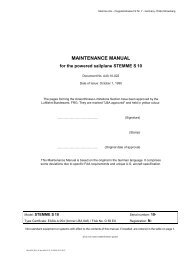
Table of Contents<br />
Installation Instructions<br />
Propeller 10AP-F for model S10-V<br />
Document number:<br />
A34-10-067E<br />
Rev. Index: 01.a<br />
page: 1 of 10<br />
1 General 1<br />
2 Documents, Materials and Tools 3<br />
3 Conversion of model S10 with normal propeller 10AP-N to model S10-V with fixed<br />
propeller 10AP-F 4<br />
4 Conversion of model S10-V with variable pitch propeller 10AP-V to model S10-V with<br />
fixed propeller 10AP-F 6<br />
Attachment A: Wiring Diagram for change of Engine Switch 8<br />
Attachment B: Illustrations 9<br />
1 General<br />
This installation instruction describes the procedures which have to be performed in combination with the<br />
equipment of the motorglider model S10-V with the fixed propeller 10AP-F as an alternative to standard,<br />
electric propeller 10AP-V. It is closely related to<br />
� Service Bulletin SB A31-10-010 „Conversion of model S10 to model S10-V“, and to<br />
� Service Bulletin SB A31-10-067 „Propeller 10AP-F for model S10-V“.<br />
The range of works which have to be carried out in connection with the installation of fixed pitch propellers<br />
10AP-F, depends greatly on the current stage of construction of the motorglider, in which the propeller will be<br />
installed. Possible starting points for the stage of construction are:<br />
� 1. Model S10 with Normal Propeller 10AP-N:<br />
With accomplishment of SB A31-10-010 and SB A31-10-067 in parallel, such motorgliders can be<br />
converted directly to a model S10-V with fixed propeller 10AP-F.<br />
Note: A conversion to variable pitch propeller 10AP-V later on is also possible. If the electrical<br />
system for the variable pitch propeller has already been installed in connection with the<br />
conversion (SB A31-10-010, procedure A), the modification can be done by the<br />
manufacturer or by a qualified Aviation Repair Organization (ARO). If the electrical system<br />
for the variable pitch propeller has not been installed (SB A31-10-010, procedure B), the<br />
modification to variable pitch propeller must be accomplished by the manufacturer.<br />
� 2. Model S10-V with variable pitch Propeller 10AP-V:<br />
Such motogliders can be converted to fixed propeller 10AP-F by following the instructions of SB A31-<br />
10-067. These operations can be accomplished by the manufacturer or by a qualified Aviation Repair<br />
Organization.<br />
erstellt: Kurzzeichen MPL geprüft: Kurzzeichen Datum: Ersetzt Ausg. vom LBA anerkannt Datum:<br />
prepared by: Signed<br />
checked by<br />
airworthiness dpt.:<br />
Signed Date:<br />
Supersedes<br />
issue of:<br />
LBA approved Date:<br />
Dalldorff Ellwanger 11.09.2003 --.--.---- ------ ------<br />
A3410067E_01a.doc / 07.01.11 09:10
F & D<br />
LBA.NSD.005<br />
A3410067E_01a.doc / 07.01.11 09:10<br />
Installation Instructions<br />
Propeller 10AP-F for model S10-V<br />
Document number:<br />
A34-10-067E<br />
Rev. Index: 01.a<br />
page: 2 of 10<br />
The following chart provides information on the conversion options between the different construction stages<br />
and the main related documents (Service Bulletins, Installation and Inspection Instructions):<br />
Model S10 Model S10-V<br />
Accomplishment of SB A31-10-010 B<br />
Accomplishment of SB A31-10-067<br />
Installation Instructions A34-10-067<br />
by Manufacturer or ARO<br />
Accomplishment of SB A31-10-010 A<br />
STEMME S10-V<br />
fixed propeller 10AP-F<br />
(without FP-electronics)<br />
Deletion of SB A31-10-010 B<br />
Deletion of SB A31-10-067<br />
Accomplishment of SB A31-10-010 A<br />
Inspection Instructions A17-14<br />
ONLY by manufacturer<br />
STEMME S10 Inspection Instructions A17-14<br />
STEMME S10-V<br />
Normal propeller 10AP-N ONLY by manufacturer<br />
variable pitch propeller 10AP-V<br />
(with VPP-electronics)<br />
Accomplishment of SB A31-10-010 A<br />
Accomplishment of SB A31-10-067<br />
Installation Instructions A34-10-067<br />
Inspection Instructions A17-14<br />
ONLY by manufacturer<br />
Accomplishment of SB A31-10-067<br />
Installation Instructions A34-10-067<br />
by Manufacturer or ARO<br />
Deletion of SB A31-10-067<br />
Inspection Instructions A17-14<br />
by Manufacturer or ARO<br />
STEMME S10-V<br />
fixed propeller 10AP-F<br />
(with VPP-electronics)<br />
A furnishing with fixed pitch propeller 10AP-F can in principle either be accomplished by the manufacturer or<br />
possibly by a qualified aviation repair organization (ARO). The corresponding workflow steps are described<br />
in detail in these Installation Instructions.<br />
A furnishing of the STEMME S10 with variable pitch propeller 10AP-V for the first time and the associated<br />
electrical components is a major task, which must be accomplished in principle only by the manufacturer and<br />
is therefore not considered in detail here.<br />
A re-assembly of the variable pitch propeller 10AP-V can either be accomplished by the manufacturer or<br />
possibly by a qualified ARO, if the electrical components of the variable pitch propeller are already installed<br />
(e.g. if the fixed propeller 10AP-F was installed in the meantime). However, such a re-assembly with variable<br />
pitch propellers 10AP-V is also not considered in detail here.<br />
If required, a set of corresponding documents can be ordered from the STEMME Company. It contains the<br />
necessary documents such as the assembly drawing A12-10AP-V, the bill of material A21-10AP-V, the<br />
Inspection Instructions A17-14, extracts from the procedural instructions 10AP-V / 1 "Installation of Propeller<br />
10AP-V" (Chapter 2.18 to 2.21 ), the procedural instructions VA A17-10AP-V / 2 "Dynamic Balancing" and<br />
the associated Inspection protocols (variable pitch propeller adjustment report, dynamic balancing report,<br />
ground test run report, weight and balance report, flight report).
F & D<br />
LBA.NSD.005<br />
2 Documents, Materials and Tools<br />
A3410067E_01a.doc / 07.01.11 09:10<br />
Installation Instructions<br />
Propeller 10AP-F for model S10-V<br />
Document number:<br />
A34-10-067E<br />
Rev. Index: 01.a<br />
page: 3 of 10<br />
Materials: conversion from: S10 S10-V<br />
part nr. P/N qty. Description (10AP-N) (10AP-V)<br />
10AP-F 1 Propeller 10AP-F X X<br />
10AP-NS 6 Bolt 10AP-NS X X<br />
D125-08 6 Washer D125-08 X<br />
10AP-V66 1 Distance Washer 10AP-V66 X<br />
10AP-V67 1 Distance Washer 10AP-V67 X<br />
10AM-K 1 Set of pre-assembled cooling air flaps - operation lever X<br />
10AA-23 4 bell-shaped element 65 shore X<br />
10A-28 4 Bushing X<br />
1 second Type Plate with new model identification and S/N at conversion S10 ==> S10-V X<br />
1 set of Placards for model S10-V X<br />
1 Electrical Replacement-Set with pre-assembled Dome switch X<br />
0,6m Locking wire L9424-1,0 for propeller bolts 10AP-NS X X<br />
1 Set of small material:<br />
Stop nuts, washers, Loctite, shrink hose, duct tape/insulating tape, cable straps etc. X X<br />
2 Blind plug for bore hole 13 mm / 0.51 in X<br />
1 Blind plug for bore hole 8 mm / 0.31 in X<br />
Tools: conversion from: S10 S10-V<br />
Description (10AP-N) (10AP-V)<br />
Standard metrical mechanic’s toolkit X X<br />
Hot-air gun X X<br />
Locking wire pliers X X<br />
Torque wrench (up to ~ 50 Nm / 40 lbf ft) X X<br />
Crimping tool X<br />
Insulation stripping pliers X<br />
Documents: conversion from: S10 S10-V<br />
part nr. P/N Ind. Description (10AP-N) (10AP-V)<br />
A-34-10-067 01.a Installation Instruction "Propeller 10AP-F for model S10-V" (document in hand) X X<br />
A40-10-110 5 Flight Manual S10-V (Rev. 5 or later) incl. replacement pages for propeller 10AP-F X X<br />
A40-10-120 11 Maintenance Manual S10-V (Revision 11 or later) X X<br />
A35-10-067 01.a Maintenance Instructions S10-V with propeller 10AP-F X X<br />
A12-10AA 21.a Assembly Drawing Front Gear attachment S10 / S10-V X<br />
A21-14AA 01.a Bill of Material Front Gear attachment S10-V X<br />
A12-10AM-K 13.b Assembly Drawing Cooling air flaps - operation S10 / S10-V X<br />
A20-10AM-K-E 13.d Bill of Material Cooling air flaps - operation X<br />
A12-10AG-00-01 20.a Assembly Drawing Front Gear, complete X<br />
A12-10AP-F-01 01.b Assembly Drawing Propeller 10AP-F X X<br />
A12-10AP-F-02 01.a Assembly Drawing Propeller 10AP-F X X<br />
A21-10AP-F 01.a Bill of Material Propeller 10AP-F X X<br />
A31-10-001 09.a SB "Review of Permissible Operating Time" (Revision 09.a or later) X X<br />
A31-10-010 02.a SB "Conversion of model S10 to model S10-V" X<br />
A31-10-067 01.a SB "Propeller 10AP-F for model S10-V" X X<br />
1001-10-a A Protocol for ground test run of motorglider STEMME S10, model: S10 und S10-V X X<br />
1001-04-c A Flight test protocol for STEMME S10 and models X X<br />
1001-12-a B Review of weights for STEMME S10, S10-V X X<br />
JAA Form One for Propeller 10AP-F X X<br />
LBA-sheet Nr. 846 for STEMME S10-V, Revision 5 or later X X<br />
Procedures: conversion from: S10 S10-V<br />
nr: Description (10AP-N) (10AP-V)<br />
1 Turning of Propeller brake drum by 90° X<br />
2 Installation of Shock-Mounts with different specification X<br />
3 Installation of fixed Propellers 10AP-F X X<br />
4 Installation of Cooling air-flaps reduction X<br />
5 Deactivation / Disassembly of components of variable pitch propeller electronics X<br />
6 Installation of Engine-Dome-switch (Engine Master switch) X<br />
7 Changes of Placards in the cabin and for electrical system X X<br />
8 Installation of second Type Plate with new Model Identification and S/N X<br />
9 Change of Flight- and Maintenance Manuals, incl. Maintenance Manual Supplement X X<br />
10 Correction of Inspection Documents (especially Weighing Protocol and Revies of Operating Times) X X<br />
11 Check and Certification of accomplished works X X<br />
12 Ground test run and Test Flight for verification X X
F & D<br />
LBA.NSD.005<br />
A3410067E_01a.doc / 07.01.11 09:10<br />
Installation Instructions<br />
Propeller 10AP-F for model S10-V<br />
3 Conversion of model S10 with normal propeller 10AP-N<br />
to model S10-V with fixed propeller 10AP-F<br />
1 Removal of Propeller Dome<br />
1.1 Remove Propeller Dome; refer to Maintenance Manual (MM)<br />
2 Removal of Normal Propeller 10AP-N<br />
2.1 Remove the old Propeller; refer to MM<br />
3 Removal of Drive Chain<br />
3.1 Remove the Drive Chain; refer to MM<br />
4 Removal of the Front Gear Attachment<br />
4.1 Remove the four Shock-Mounts from the front fuselage bulkhead; refer to MM and A12-14AA<br />
5 Modification of the Front Gear Attachment<br />
Document number:<br />
A34-10-067E<br />
Rev. Index: 01.a<br />
Preliminary Note:<br />
All work steps according to Bill of Material A21-14AA and Drawing A12-10AA with details for model S10-V<br />
Replacement of the bell-shaped elements in the four Shock-mounts from 55shore (P/N: 10AA-24, old) to<br />
5.1<br />
65shore (P/N: 10AA-23, new)<br />
Replacement of the bushings in the Shock-mounts from 40mm / 1.58 in lenght (P/N: 10AA-08, old) to 35mm<br />
5.2<br />
/ 1.38 in length (P/N: 10AA-28, new, coated blue)<br />
6 Transformation of Propeller Brake drum<br />
The brake drum 10AG-12 has to be installed turned by 90° around the propeller shaft on the back side of the<br />
propeller shaft of the belt drive 10AG (==> both of the two flutes for the propeller positioning in the brake<br />
6.1 drum have to be directed towards the propeller blades). Therefore remove the brake drum from the propeller<br />
shaft and re-assemble with turned angle. The washers between brake drum and belt pulley must not be<br />
forgotten when assembling (refer to assembly drawing A12-10AG-00-01).<br />
7 Installation of Dome-Engine-Master switch - Modification Activation-Bus, Engine-Bus and Starter-Bus<br />
Preliminary Note:<br />
The modification described in the following is for removal of the manually operated snap switch of the<br />
Activation-Bus of the Engine-Bus. The Engine-Bus is then switched on by the propeller dome end postion<br />
switch (with locking of dome operation lever). To prepare the propeller dome switch for this function, the<br />
Starter-Bus has to be modified as well. After modification, the engine start does not depend on the propeller<br />
dome switch any longer. However an accidental starting of the engine with closed propeller dome is not<br />
possible, because the entire Engine-Bus (and thus the Starter-Bus) is switched on by the propeller dome<br />
switch. The conversion with already installed Engine-Emergency-Switch is described. At very early serial<br />
numbers, this switch may still be missing and must be upgraded.<br />
Refer to Attachment A of this document to find a wiring diagram for the described modification of the Engine<br />
Master Switch.<br />
7.1 Remove Voltmeter, Oil pressure gauge and Tachometer for better working space<br />
7.2 Remove Engine Master Switch and disconnect cables 002(2x), 12, 70, 71<br />
7.3<br />
Remove Engine-Emergency-Switch and disconnect cables 004, 49, wind up spiral cable shield up to main<br />
cableform<br />
7.4<br />
Change mounting position of Avionics-Switch „Main-/Booster Battery“ to the position of the old Engine<br />
Master Switch<br />
7.5<br />
Extend cable lengths of cables 002 (2x), 12, 70, 71 (former Engine Master Switch) up to Engine Emergency<br />
Switch (about 20cm) and to the propeller dome switch (about 65cm)<br />
7.6 Wrap the new cables with spiral cable shield and pay attention to correct routing of cables<br />
7.7 Remove CB landing gear, landing gear switch and Avionic switch for better working space<br />
7.8 Disconnect cables 49 (2x) from Ingnition Switch, cut off ring ear for clamping.<br />
Disconnect cables 004, 49 from propeller dome switch, wind up spiral cable shield up to main cableform, pull<br />
7.9 cable 49 out of the main cableform, insulate cable 004 and embed it into the main cableform rearward of the<br />
switch bank.<br />
7.10 Connect cable 004 (former Engine Emergency Switch) to Ignition Switch.<br />
7.11 Install removed switches back to switch bank.<br />
7.12 Install removed instruments. Close unused openings of the instrument panel with a cap.<br />
8 Installation Cooling-Air Flaps Operation<br />
8.1<br />
Install Cooling-Air Flaps Reduction according to Bill of Material A20-10AM-K-E, Drawing A12-10AM-K and<br />
illustrations in the attachment of this document.<br />
9 Installation of Front Gear Attachment<br />
9.1 Install the four modified Shock-Mounts to the front fuselage bulkhead; refer to Drawing A12-10AA<br />
10 Installation Drive Chain<br />
10.1 Install the Drive Chain to the front fuselage; refer to MM<br />
page: 4 of 10<br />
Check Note
F & D<br />
LBA.NSD.005<br />
A3410067E_01a.doc / 07.01.11 09:10<br />
Installation Instructions<br />
Propeller 10AP-F for model S10-V<br />
Document number:<br />
A34-10-067E<br />
Rev. Index: 01.a<br />
11 Installation of new Propeller 10AP-F<br />
Install the propeller 10AP-F to the belt drive according to drawing A12-10AP-F. Use six new bolts 10AP-NS<br />
11.1 therefore. Do not forget to use washers D125-08 between zwischen bolt head 10AP-NS and middle section<br />
10AP-F01 of the bolt.<br />
Check clearance:<br />
The propeller blades have to be retracted and extended over a complete propeller rotation several times by<br />
hand to simulate the procedure. If the propeller blade trailing edges a) near the position fully retracted collide<br />
11.2 only slightly with the outer rim of the mounting rods from the front gear attachment b) or with the front<br />
fuselage rim, a distance washer (10AP-V67 (1,0mm / 0.04 in) or 10AP-V66 (1,5mm / 0.06 in)) has to be<br />
installed between belt pulley and central section 10AP-F01 of the new propeller 10AP-F. The phase of the<br />
distance washer bore hole must point in the direction of belt pulley.<br />
Tighten screws 10AP-NS according to MM: first with 10Nm crosswise, then with 30Nm / 22.1 lbf ft<br />
11.3<br />
crosswise. Lock screws with locking wire L9424-1,0.<br />
12 Installatio Propeller Dome<br />
12.1 Install the propeller dome; refer to MM.<br />
13 Installation of second Type Plate (also refer to SB A31-10-010)<br />
13.1 Install the second Type Plate with new model identification and S/N next to the old Type Plate.<br />
13.2 Invalidate the old Type Plate.<br />
14 Correction of Weighing Protocol<br />
Correct the Weighing Protocoll according to SB A31-10-010 by calculation (review of weights 1001-12-a). A<br />
14.1<br />
new weighing is of course also possible.<br />
15 Update the Review of Operation Time<br />
Update the review of operation time in the maintenance manual. Delete the old propeller and adopt new<br />
15.1 propeller 10AP-F. Permissible operating time has to be taken from latest issue of SB A31-10-001 (issue 09.a<br />
with release of propeller).<br />
16 Modification of the Manuals<br />
Replace Flight Manual of S10 with Flight Manual of S10-V (A40-10-110, Revision 5 or later). Adopt S/N-<br />
16.1 specific date and information to the new Flight Manual, changed model identification and S/N has to be taken<br />
into consideration.<br />
16.2 Insert replacement pages for propeller 10AP-F (Revision 5 or later) into Flight Manual S10-V.<br />
16.3<br />
Replace Maintenance Manual S10 by Maintenance Manual S10-V (A40-10-120, Revision 11 or later). Adopt<br />
S/N-specific date and information to the new Maintenance Manual, changed model identification and S/N has<br />
to be taken into consideration.<br />
16.4 Insert Maintenance Instruction A35-10-067 for propeller 10AP-F into the Maintenance Manual S10-V.<br />
16.5<br />
Insert provided documents (Form One, Certification sheet for propeller 10AP-F) into the Maintenance<br />
Manual.<br />
17 Cockpit Placards<br />
page: 5 of 10<br />
17.1<br />
Check Cockpit Placards and add Placards according to MM S10-V and Maintenance Instruction A35-10-067<br />
for propeller 10AP-F. Especially add placards for Cooling-Air flaps (Pos-Nr. 19) and replace the great<br />
placard on the center console by a new one (according Flight Manual, p. 2-8a.) with the valid weighing data.<br />
18 Ground Test Run<br />
18.1 Perform Ground Test Run (according to Ground Test Run Protocol 1001-10-a).<br />
19 Test Flight<br />
19.1 Perform Test Flight for verification (according to Test Fligth Protocol 1001-04-c).<br />
20 Inspection and Certification of the works by approved Certifying Staff<br />
20.1 Inspection of all performed works by approved Certifying Staff.<br />
20.2<br />
20.3<br />
Add SB A31-10-010 and SB A31-10-067 to list of Service Instructions/Service Bulletins in the Maintenance Manual.<br />
Insert certifications of all works and statements of Service Bulletins in the A/C logbook, as well as changed<br />
model and S/N.<br />
Check Note
F & D<br />
LBA.NSD.005<br />
A3410067E_01a.doc / 07.01.11 09:10<br />
Installation Instructions<br />
Propeller 10AP-F for model S10-V<br />
4 Conversion of model S10-V with variable pitch propeller 10AP-V<br />
to model S10-V with fixed propeller 10AP-F<br />
Document number:<br />
A34-10-067E<br />
Rev. Index: 01.a<br />
1 Removal of Propeller Dome<br />
1.1 Remove the Propeller Dome; refer to Maintenance Manual (MM).<br />
2 Removal of Variable Pitch Propellers 10AP-V, incl. Carbon Brushes on mounting rod of Front Gear Base Plate<br />
2.1<br />
Remove the old propeller incl. the carbon brushes for the electrical pitch adjustment mechanics; refer to MM.<br />
3 Removal Drive Chain<br />
3.1 Remove the Drive Chain; refer to MM<br />
4<br />
Electrical System: Deactivation of electric control for the Variable Pitch Propeller 10AP-V<br />
Preliminary Note:<br />
The Control- and Power-Bus of the Propeller Pitch Control are deactivated by disconnection of the cables<br />
and removal of fuses/CB's, switches and indication lights. The cables have to remain in the aircraft.<br />
Power-Bus:<br />
4.1<br />
Disconnect cable KF1E from the main relay respectively the plus terminal of the battery (depending of state<br />
of construction).<br />
4.2 Disconnect cable KF3EN from negative terminal of the battery.<br />
4.3 Insulate free cable sockets with shrink hose or insulating tape.<br />
4.4 Mount the cable heads to the existing cableform.<br />
4.5 Disconnect cables KF1G, KF3FN, KF14KN from the carbon brushes.<br />
4.6 Insulate free cable sockets with shrink hose or insulating tape.<br />
4.7 Mount the cable heads to the existing cableform in the Cockpit.<br />
4.8 Remove Circuit Breaker 17KF (15A).<br />
4.9 Disconnect cables KF1E, KF1F from the CB 17 KF.<br />
4.10 Insulate free cable sockets with shrink hose or insulating tape.<br />
4.11 Mount the cable heads to the existing cableform in the Cockpit.<br />
5 Control-Bus:<br />
5.1 Remove Fuse 9KF from its socket.<br />
5.2 Remove relay 12KF and 18KF from its socket.<br />
5.3<br />
Disconnect patch plug from indicating module for T/O-blade position 14KF (Black Box) and remove<br />
indicating module<br />
5.4 Disconnect patch plug at the throttle lever console and remove switch 10KF and indicating light 15KF.<br />
5.5 Insulate free cable sockets with shrink hose or insulating tape and mount to the existing cableform.<br />
5.6 Close unused openings for switch, indicating light and CB with cap.<br />
5.7 Remove Placard for propeller pitch adjustment at the throttle lever console and instrument panel.<br />
5.8<br />
The Function-Test-Switch for the Propeller pitch adjustment remains at the front gear bulkhead (otherwise<br />
the bonded noise damping mat would need to be removed).<br />
6 Installation Drive Chain<br />
6.1 Install the Drive Chain into the fuselage; refer to MM<br />
7 Installation of new Propeller 10AP-F<br />
Install the new propellers 10AP-F to the belt drive 10AG according to Drawing A12-10AP-F. Use six new<br />
7.1 bolts 10AP-NS therefore. The old washers D433-08 (old) have to be replaced by a new set of washers D125-<br />
08 (new) between bolt head 10AP-NS and central part of the bolt 10AP-F01.<br />
7.2<br />
Check clearance:<br />
The propeller blades have to be retracted and extended over a complete propeller rotation several times by<br />
hand to simulate the procedure. If the propeller blade trailing edges a) near the position fully retracted collide<br />
only slightly with the outer rim of the mounting rods from the front gear attachment b) or with the front<br />
fuselage rim, a distance washer (10AP-V67 (1,0mm / 0.04 in) or 10AP-V66 (1,5mm / 0.06 in)) has to be<br />
installed between belt pulley and central section 10AP-F01 of the new propeller 10AP-F. The phase of the<br />
distance washer bore hole must point into the direction of belt pulley.<br />
Tighten screws 10AP-NS according to MM: first with 10Nm / 7.4 lbf ft crosswise, then with 30Nm / 22.1 lbf ft<br />
7.3<br />
crosswise. Lock screws with locking wire L9424-1,0.<br />
8 Installation Dome<br />
8.1 Install the propeller dome; refer to MM.<br />
9 Correction of Weighing Protocol<br />
Correct the Weighing Protocoll according to SB A31-10-067 by calculation (review of weights 1001-12-a). A<br />
9.1<br />
new weighing is of course also possible.<br />
10 Update the Review of Operation Time<br />
Update the review of operation time in the maintenance manual. Delete the old propeller and adopt new<br />
10.1 propeller 10AP-F. Permissible operating time has to be taken from latest issue of SB A31-10-001 (issue 09.a<br />
with release of propeller).<br />
page: 6 of 10<br />
Check Note
F & D<br />
LBA.NSD.005<br />
A3410067E_01a.doc / 07.01.11 09:10<br />
Installation Instructions<br />
Propeller 10AP-F for model S10-V<br />
Document number:<br />
A34-10-067E<br />
Rev. Index: 01.a<br />
11 Modification of the Manuals<br />
Update to Revision 5 (or later) the Flight Manual of the S10-V (A40-10-110). S/N-specific date and<br />
11.1 information, changed model identification and S/N have to be taken into consideration by adding<br />
replacement pages.<br />
11.2 Insert replacement pages for propeller 10AP-F (Revision 5 or later) into Flight Manual S10-V.<br />
11.3<br />
Update to Revision 11 (or later) des S10-Wartungshandbuchs (A40-10-120) durchführen, dabei ggf.<br />
werknummernspezifische Angaben auf die berichtigten Seiten des Wartungshandbuchs übernehmen.<br />
11.4 Insert Maintenance Instruction A35-10-067 for propeller 10AP-F into the Maintenance Manual S10-V.<br />
11.5<br />
Insert provided documents (Form One, Certification sheet for propeller 10AP-F) into the Maintenance<br />
Manual.<br />
12 Cockpit Placards<br />
Check Cockpit Placards and add Placards according to MM S10-V and Maintenance Instruction A35-10-067<br />
12.1<br />
for propeller 10AP-F. Especially remove placards a) for the propeller switch (Pos-Nr. 14, 15, 16) and b) for<br />
the CB for the variable pitch control electronics. Replace the great placard on the center console with a new<br />
one (according Flight Manual, p. 2-8a.) with the valid weighing data.<br />
13 Ground Test Run<br />
13.1 Perform Ground Test Run (according to Ground Test Run Protocol 1001-10-a).<br />
14 Test Flight<br />
14.1 Perform Test Flight for verification (according to Test Fligth Protocol 1001-04-c).<br />
15 Inspection and Certification of the works by approved Certifying Staff<br />
15.1 Inspection of all performed works by approved Certifying Staff.<br />
15.2 Add SB A31-10-067 to list of Service Instructions/Service Bulletins in the Maintenance Manual.<br />
15.3 Insert certifications of all works and statements of Service Bulletins to the A/C logbook.<br />
page: 7 of 10<br />
Check Note
F & D<br />
LBA.NSD.005<br />
Attachment A: Wiring Diagram for change of Engine Switch<br />
Engine M otor-<br />
Emergency N otschalter<br />
Switch<br />
A3410067E_01a.doc / 07.01.11 09:10<br />
2<br />
2a<br />
2b<br />
1<br />
2<br />
1a<br />
2a<br />
2<br />
2a<br />
2b<br />
1<br />
1a<br />
Installation Instructions<br />
Propeller 10AP-F for model S10-V<br />
Engine-Bus M otorschi ene<br />
Main-Bus H auptschi ene<br />
Engine-Bus<br />
M otorschi ene<br />
Main-Bus H auptschi ene<br />
1b<br />
2b<br />
1<br />
1a<br />
Si 0,4A<br />
004 004<br />
49 49<br />
48<br />
1b<br />
zum Starterknopf<br />
to Ignition Switch<br />
Ignition<br />
Z ündschalter<br />
Switch<br />
002<br />
002<br />
PropDom<br />
Propeller<br />
Schalter<br />
Dome Switch<br />
2<br />
1<br />
MEngine otorschalter<br />
Master<br />
1b<br />
Switch<br />
2a 2b 1a 1b<br />
alter old state Zustand<br />
70<br />
Si 0,4A<br />
71<br />
M otorrelais<br />
Engine Relay<br />
01 27.08.03 Baum<br />
Z ust. Änderung smitt. D atum N ame<br />
12<br />
Bear b.<br />
Gepr.<br />
M PL<br />
2<br />
2a<br />
2b<br />
1<br />
1a<br />
48<br />
Si 0,4A<br />
004<br />
1b<br />
zum Starterknopf<br />
to Ignition Switch<br />
D atum N ame<br />
LBA.NSD .005<br />
F lug platzstr. F2 N r. 7<br />
D -15344 Strausberg<br />
Ignition Z ündschalter<br />
Switch<br />
27.08.03 Baum<br />
PropDom Propeller<br />
Dome Schalter Switch<br />
70<br />
2<br />
2a<br />
Erzeug nis-Bezeichnung<br />
U nterlagen-N r. Blatt<br />
Ersatz für<br />
Si 0,4A<br />
2b<br />
71<br />
neuer new state Zustand<br />
1<br />
1a<br />
1b<br />
002<br />
70<br />
71<br />
MEngine otorrelais Relay<br />
2<br />
2a<br />
12<br />
2b<br />
1<br />
1a<br />
002<br />
MEngine otor-<br />
NEmergency otschalter<br />
Switch<br />
1b<br />
12<br />
Document number:<br />
A34-10-067E<br />
12<br />
Rev. Index: 01.a<br />
002<br />
Modification Umrüstung Motorschalter Engine Switch bei for<br />
conversion Wandlung S10 in to S10-V S10-V<br />
page: 8 of 10<br />
Bl.
F & D<br />
LBA.NSD.005<br />
Attachment B: Illustrations<br />
A3410067E_01a.doc / 07.01.11 09:10<br />
Installation Instruction<br />
Propeller 10AP-F for model S10-V<br />
Document number:<br />
A34-10-067E<br />
Rev. Index: 01.a<br />
page: 9 of 10
F & D<br />
LBA.NSD.005<br />
A3410067E_01a.doc / 07.01.11 09:10<br />
Installation Instruction<br />
Propeller 10AP-F for model S10-V<br />
Document number:<br />
A34-10-067E<br />
Rev. Index: 01.a<br />
page: 10 of 10