MAINTENANCE MANUAL - Stemme AG
MAINTENANCE MANUAL - Stemme AG
MAINTENANCE MANUAL - Stemme AG

You also want an ePaper? Increase the reach of your titles
YUMPU automatically turns print PDFs into web optimized ePapers that Google loves.
A4010022_B12_97.doc-0/04.12.07 16:33/05.12.07 08:57<br />
<strong>Stemme</strong> <strong>AG</strong> – Flugplatzstrasse F2 Nr. 7 - Germany-15344 Strausberg<br />
<strong>MAINTENANCE</strong> <strong>MANUAL</strong><br />
for the powered sailplane STEMME S 10<br />
Document No. A40-10-022<br />
Date of Issue: October 1, 1990<br />
The pages forming the Airworthiness Limitations Section have been approved by the<br />
Luftfahrt-Bundesamt, FRG. They are marked "LBA approved" and held in yellow colour.<br />
................................................ (Signature)<br />
(Stamp)<br />
................................................ (Original date of approval)<br />
This Maintenance Manual is based on the original in the German language. It comprises<br />
some deviations due to specific FAA requirements and unique U.S. aircraft specification.<br />
Model: STEMME S 10 Serial number: 10-<br />
Type Certificate: EASA.A.054 (former LBA 846) / FAA No. G 58 EU Registration: N-<br />
Non-standard equipment or systems with effect to the contents of this manual, if installed, are entered in the table on page 1.<br />
Druck-Info: Datei enthält 68 Seiten gesamt
Maintenance Manual STEMME S 10 Date of Issue Oct. 1, 1990 page: 2-1<br />
0.1 Record of Amendments<br />
Amendment No.: 12 Date: Nov. 30. 2007<br />
Any amendment of the present manual must be recorded in the following table. Exempted are:<br />
Data relating to the installation of alternative equipment (page 1)<br />
Data relating to the installation of supplemental or additional equipment (page 51)<br />
Deletion of inapplicable text passages pursuant to the Service Bulletin A31-10-008.<br />
The list of amendments on this page and the list of effective pages on the next page are assigned to the<br />
serial number. The indicated revision no. in the headline of these pages does not change with later entries<br />
in the lists.<br />
Information as to which amendments must be included in the present Manual can be seen from the current<br />
"Record of Airworthiness Directives and Service Bulletins" (see Annex B, doc. no. A08-10-000).<br />
The new or amended text of the latest amendment will be marked on the revised page by a black vertical line<br />
on the right hand margin. Any Amendment Numbers applied to the specific page and the date of the most<br />
recent amendment is indicated on the right hand side in the headline of each page. In text passages<br />
concerned by the installation of alternative equipment, the text for both versions is included in [ ]; the text not<br />
applicable to the serial number concerned must be crossed out. For further information please refer to<br />
Section 9.3 or to the Service Bulletin A31-10-008.<br />
The inspector certifies by his signature at the same time the correct transfer of the information specific to the<br />
serial number (deletion of inapplicable text passages).<br />
Am.<br />
No.<br />
Affected<br />
Sections<br />
Removed Pages included Pages<br />
Amendment<br />
Date<br />
Date of<br />
inclusion<br />
Signature<br />
1 0, 4 4, 21 4, 21 Aug. 15, 1991 Aug. 15, 1991 ex works<br />
2 0, 4 4, 21, 22 4, 21, 22 March 1, 1993 March 1, 1993 ex works<br />
3 0, 9, 10, 11, 12,<br />
13<br />
1, 2, 3, 5, 51, 53,<br />
54, 55, 56<br />
4 3, 12 14, 15, 47*,<br />
Fig. 3.3.2.a * ,<br />
Fig. 3.6.b*<br />
Title p., 1, 2, 3, 5,<br />
51, 53 to 56,<br />
Cover p. Annex A,<br />
B, and C<br />
14, 15, 47*,<br />
Fig. 3.3.2.a*,<br />
Fig. 3.6.b*<br />
5 not issued<br />
6 3, 4, 10, 12 13, 25, 55,<br />
Fig. 3.2.b<br />
7 3, 5, 12 4, 13, 14, 24 ··· 26,<br />
Fig. 3.2.a ··· g,<br />
Fig. 6.4.1.a<br />
13, 25, 55,<br />
Fig. 3.2.b<br />
4, 13, 14, 24 ··· 26,<br />
Fig. 3.2.a ··· g,<br />
Fig. 6.4.1.a<br />
July 1, 1993 July 1, 1993 ex works<br />
May 26, 1993 May 26, 1993 ex works<br />
Feb. 10, 1994 Feb. 10, 1994 ex works<br />
Dec. 05, 1994 Dec. 05, 1994 ex works<br />
8 0, 5 2 ··· 5, 26 ··· 30 2 ··· 5, 26 ··· 30 Aug. 8, 1996 Aug. 8, 1996 ex works<br />
9 3, 5, 6, 7, 8 2...5, 19 ,28, 29, 33,<br />
42, 44, 45, 48<br />
2...5, 19 ,28, 29, 33,<br />
42, 44, 45, 48<br />
10 0,4 2, 3, 21, 22 2, 3, 21, 22-1, 22-2 March 16, 2005<br />
11 0,3,4,5,7,9 2..5, 18, 21, 22-1,<br />
22-2, 27...30, 36,<br />
38, 51..54<br />
2..5, 18, 21, 22-1,<br />
22-2, 27...30, 36,<br />
38, 51..53, 54-1,<br />
54-2<br />
April 19, 1999 April 19, 1999<br />
May 25. 2005<br />
*<br />
These pages may only be incorporated with the quoted amendment number if the alternative equipment<br />
item requiring the amendment is installed in the individual aircraft - please check the entries on page 1 for<br />
the corresponding SB. Amendment no. 4 is mandatory for U.S.A.<br />
A4010022_B12_97.doc-2/04.12.07 16:33/05.12.07 08:58 Doc. No. A40-10-022
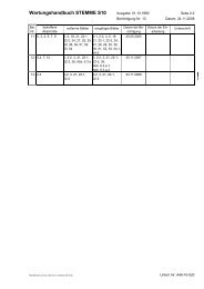
Maintenance Manual STEMME S 10 Date of Issue Oct. 1, 1990 page: 2-2<br />
Am.<br />
No.<br />
Affected<br />
Sections<br />
12 0, 7, 4, 12 Title, 2, 3, 21, 22-1,<br />
22-1, 38, Fig. 6.3.a,<br />
Removed Pages included Pages<br />
Title, 2-1, 2-2, 3, 21,<br />
22-1, 22-1, 38, Fig.<br />
6.3.a-1, Fig. 6.3.a-2<br />
Amendment No.: 12 Date: Nov 30. 2007<br />
Amendment<br />
Date<br />
Nov 30. 2007<br />
Date of<br />
inclusion<br />
Signature<br />
A4010022_B12_97.doc-3/04.12.07 16:33/05.12.07 08:57 Doc. No. A40-10-022
Maintenance Manual STEMME S 10 Date of Issue Oct. 1, 1990 page: 3<br />
0.2 List of effective pages<br />
Amendment No.: 12 Date: Nov. 30. 2007<br />
This record is valid only for the Serial No. specified on the title page. Any amendment is contained ex works<br />
that is effective for this Maintenance Manual at Aug. 08, 1996 (amendment status 08). Related to alternative<br />
equipment, only those amendments is provided for that correspond to the entries on page 1, amendments<br />
that are included later must be entered by hand.<br />
Section Page Am. No. Date<br />
-- Title 12 Nov. 30, 07<br />
-- 1 3 July 1, 93<br />
0.1 2-1 12 Nov. 30, 07<br />
0.1 2-2 12 Nov. 30, 07<br />
0.2 3 12 Nov. 30, 07<br />
0.3 4 11 May 25. 05<br />
0.3 5 11 May 25. 05<br />
res. 6 Oct. 1, 90<br />
1 7 Oct. 1, 90<br />
res. 8 Oct. 1, 90<br />
2 9 Oct. 1, 90<br />
2 10 Oct. 1, 90<br />
res. 11 Oct. 1, 90<br />
3.1 12 Oct. 1, 90<br />
3.1/3.2 13 6, 7 Dec. 5, 94<br />
3.3 14 4, 7 Dec. 5, 94<br />
3.3 15 4 May 26, 93<br />
3.3 16 Oct. 1, 90<br />
3.4 17 Oct. 1, 90<br />
3.5/3.6 18 11 May 25. 05<br />
3.7/3.8 19 9 Apr. 19, 99<br />
res. 20 Oct. 1, 90<br />
4 21 12 Nov. 30, 07<br />
4 22-1 12 Nov. 30, 07<br />
4 22-2 12 Nov. 30, 07<br />
5.1/5.2 23 Oct. 1, 90<br />
5.2 24 7 Dec. 5, 94<br />
5.2 25 6, 7 Dec. 5, 94<br />
5.2 26 7, 8 Aug. 8, 96<br />
5.2 27 11 May 25. 05<br />
5.2 28 11 May 25. 05<br />
5.2 29 11 May 25. 05<br />
Section Page Am. No. Date<br />
5.3 30 11 May 25. 05<br />
6.1/6.3 31 Oct. 1, 90<br />
6.4/6.5 32 Oct. 1, 90<br />
6.6 33 9 Apr. 19, 99<br />
res. 34 Oct. 1, 90<br />
7.1/7.3 35 Oct. 1, 90<br />
7.3 36 11 May 25. 05<br />
7.3 37 Oct. 1, 90<br />
7.3/7.4 38 12 Nov. 30, 07<br />
7.4 39 Oct. 1, 90<br />
7.4 40 Oct. 1, 90<br />
7.4/7.6 41 Oct. 1, 90<br />
7.7/7.8 42 9 Apr. 19, 99<br />
res. 43 Oct. 1, 90<br />
8 44 9 Apr. 19, 99<br />
8 45 9 Apr. 19, 99<br />
8 46 Oct. 1, 90<br />
8 47 4 May 26, 93<br />
8 48 9 Apr. 19, 99<br />
8 49 Oct. 1, 90<br />
res. 50 Oct. 1, 90<br />
9.1 51 11 May 25. 05<br />
9.2, 9.3 52 11 May 25. 05<br />
9.3 53 11 May 25. 05<br />
9.3 54-1 11 May 25. 05<br />
9.3 54-2 11 May 25. 05<br />
10, 11 55 3, 6 Feb.10, 94<br />
12 56 3 July 1, 93<br />
Figure to<br />
Section<br />
Am. No. Am. Date<br />
2.a Oct. 1, 90<br />
3.2.a 7 Dec. 5, 94<br />
3.2.b 7 Dec. 5, 94<br />
3.2.c 7 Dec. 5, 94<br />
3.2.d 7 Dec. 5, 94<br />
3.2.e 7 Dec. 5, 94<br />
3.2.f 7 Dec. 5, 94<br />
3.2.g 7 Dec. 5, 94<br />
3.3.a Oct. 1, 90<br />
3.3.2.a 4 May 26, 93<br />
3.4.1.a Oct. 1, 90<br />
3.5.a Oct. 1, 90<br />
3.5.b Oct. 1, 90<br />
3.6 Oct. 1, 90<br />
3.6.a-1 12 Nov. 30, 07<br />
3.6.a-2 12 Nov. 30, 07<br />
3.6.b Oct. 1, 90<br />
3.6.c Oct. 1, 90<br />
3.6.d Oct. 1, 90<br />
3.6.e Oct. 1, 90<br />
3.6.f Oct. 1, 90<br />
6.3.a Oct. 1, 90<br />
6.3.b Oct. 1, 90<br />
6.4.1.a 7 Dec. 5, 94<br />
6.4.2.a Oct. 1, 90<br />
7.4.1.a Oct. 1, 90<br />
Annex A<br />
(Cover Page)<br />
Annex B<br />
(Cover Page)<br />
Annex C<br />
(Cover Page)<br />
3 July 1,1993<br />
3 July 1,1993<br />
3 July 1,1993<br />
A4010022_B12_97.doc-3/05.12.07 09:00/05.12.07 09:00 Doc. No. A40-10-022
Maintenance Manual STEMME S10 Date of Issue: Oct. 1, 1990 page: 21<br />
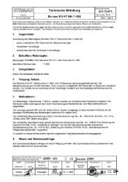
4. Airworthiness Limitations Section<br />
Amendment No.: 12 Date: Nov 30. 2007<br />
LBA approved<br />
This section is FAA-approved for U.S. registered powered sailplanes in accordance with the provisions of<br />
14 CFR Section 21.29. In addition, this section is required by FAA Type Certificate No. G 58 EU and it<br />
specifies maintenance required under 14 CFR Sections 43.16 and 91.163 unless an alternative program has<br />
been FAA-approved.<br />
The permissible operating times of all parts, components and assemblies assigned for installation - in series<br />
or optional - in the powered sailplane STEMME S10 and subject to service life limitations, are notified by the<br />
Service Bulletin no. A31-10-001. When the limitation of at least one item changes, this SB will be reissued in<br />
a revised version. The document no. will be maintained in this case, the amendment no. will be advanced<br />
(the letter in the amendment index is for internal use only).<br />
The pages of this section are printed on yellow paper for better discernment. They may not be revised without<br />
FAA engineering approval. Regulations upon keeping of service records must be observed.<br />
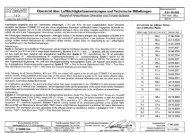
Excerpt of Service Bulletin A31-10-001 Amendment-No: 12.a: Review of permissible operating times:<br />
No.<br />
S10<br />
Model Permissible op. time by<br />
S10-V<br />
S10-VT<br />
Part/Assembly/<br />
Equipment<br />
1 X X X Airframe<br />
(Composite structure)<br />
2 X X Limbach Engine<br />
Manufacturer,<br />
Type<br />
Part No.<br />
(STEMME)<br />
Overhaul<br />
(TBO)<br />
Replaceme<br />
nt<br />
NOTES<br />
STEMME sundry 6000 h 6000 h (1)<br />
Limbach<br />
L 2400 EB 1.D<br />
L 2400 EB 1.AD<br />
10AM-MOL (2)<br />
3 X X Magneto for Limbach Slick 4230 (from Limbach) (2)<br />
4 X Rotax Engine<br />
5 X<br />
Propeller<br />
(fixed pitch)<br />
ROTAX 914<br />
F2/S1<br />
11AM-M<br />
1200 h<br />
(12 years)<br />
(5)(8)<br />
STEMME 10AP-N 400 h (3)(4)<br />
6 X Lateral parts STEMME<br />
10AP-N01<br />
10AP-N11<br />
1000h (4)<br />
7 X Fix-Pitch Propeller STEMME 10AP-F 400 h (3) (4)<br />
8 X Centre Part STEMME 10AP-F01 2000 h (4)<br />
9 X Variable pitch propeller STEMME 10AP-V<br />
200 h<br />
(5 years)<br />
(3)(4)(10)<br />
10 X Variable pitch propeller STEMME 11AP-V<br />
200 h<br />
(5 years)<br />
(3)(4)(10)<br />
11 X X Propeller hub STEMME 10AP-V01 2000h (4)<br />
12 X<br />
Propeller fork and<br />
X<br />
its fastening<br />
STEMME<br />
10AP-V88,<br />
-V77, -V78, -VU<br />
400h (3)(4)<br />
13 X X<br />
Reduction Gear<br />
(vee-belts)<br />
STEMME 10<strong>AG</strong> 400 h (3)(4)<br />
14<br />
Reduction Gear<br />
X<br />
(cog wheels)<br />
STEMME 11<strong>AG</strong> 1000 h (3)(4)<br />
15 X Gear suspension STEMME 10AA<br />
1000 h<br />
(12 years)<br />
(4)(11)<br />
16 X Gear suspension STEMME 14AA<br />
1000 h<br />
(12 years)<br />
(4)(11)<br />
17 X Gear suspension STEMME 11AA<br />
1000 h<br />
(12 years)<br />
(4)(11)<br />
18 X X<br />
Flywheel clutch<br />
(2 flyweights)<br />
STEMME 10AK 400 h (3)(4)<br />
A4010022_B12_97.doc-21/04.12.07 16:25/04.12.07 16:28 Doc. No: A40-10-022
Maintenance Manual STEMME S10 Date of Issue: Oct. 1, 1990 page: 22-1<br />
No.<br />
S10<br />
Amendment No.: 12 Date: Nov 30. 2007<br />
LBA approved<br />
Model Permissible op. time by<br />
S10-V<br />
S10-VT<br />
Part/Assembly/<br />
Equipment<br />
Manufacturer,<br />
Type<br />
Part No.<br />
(STEMME)<br />
Overhaul<br />
(TBO)<br />
Replaceme<br />
nt<br />
NOTES<br />
19<br />
Flywheel clutch<br />
X<br />
(3 flyweights)<br />
STEMME 11AK 400 h (3)(4)<br />
20 X X Driveshaft<br />
Ciba-Geigy<br />
(without P/N ref.)<br />
10AS-07 800 h (3)(4)(9)<br />
21 X X X Driveshaft<br />
Glaenzer-Spicer<br />
19.01.01.xxx<br />
10AS-07 800 h (3)(4)(9)<br />
22 X X X Driveshaft<br />
MAN Techn. <strong>AG</strong><br />
95.0700.00.000<br />
10AS-W 800 h (3)(4)(9)<br />
23 X X X Driveshaft STEMME 10AS-F 800 h (3)(4)(9)<br />
24<br />
rubber parts of the<br />
X<br />
engine<br />
Rotax sundry 5 years (7)<br />
25 X X<br />
Rubber parts of the<br />
clutch<br />
STEMME<br />
10AK-43<br />
10AK-48<br />
12 years<br />
26 X X<br />
flexible disk of the drive<br />
shaft system<br />
STEMME 10AS-09 12 years<br />
27<br />
flexible disk of the drive<br />
X<br />
shaft system<br />
STEMME 11AS-09 12 years<br />
28 X X Fuel Hoses STEMME 10AB-... - 5 years<br />
29 X X Fuel hoses STEMME HZ-KSL014 - 5 years<br />
30 X X X Fuel Hoses STEMME HZ-KSL010 - 5 years<br />
31 X X Lubrication Hoses STEMME 10AM-KÖS / ~T - 5 years<br />
32 X Lubrication Hoses STEMME 11AM-O... - 5 years<br />
33 X Coolant Hoses STEMME 11AM-W... - 5 years<br />
34 X X X Brake Hoses sundry 10FO-B06 - 10 years<br />
35 X X X Safety Harnesses sundry 10C-08/-09 - 12 years (6)<br />
36 X X<br />
Control Rod<br />
X<br />
Connectors<br />
L'Hotellier 10M-098/-099 (2)<br />
37 X fuel check valve <strong>Stemme</strong> 11AB-M03 5 years 10 years (12)<br />
On expiry of a part’s permissible operating times the affected part has to be sent to the manufacturer or to a<br />
from the manufacturer approved repair/overhaul workshop for inspection. The organisation has to decide if<br />
further use is possible after the inspection, or if an replacement or overhaul or repair is necessary.<br />
If the limitation is given in operating hours and in a calendar period (year), the first occurring case applies.<br />
If further equipment subject to service life limitations is installed, the overhaul intervals and service life limits<br />
prescribed by the respective manufacturer must be observed. The item has to be entered in the form Review<br />
of Operating times.<br />
A4010022_B12_97.doc-21/04.12.07 16:25/04.12.07 16:28 Doc. No: A40-10-022
Maintenance Manual STEMME S10 Date of Issue: Oct. 1, 1990 page: 22-2<br />
NOTES:<br />
Amendment No.: 12 Date: Nov 30. 2007<br />
LBA approved<br />
(1) Extension of service life exceeding 6000 h can be achieved only for individual airplanes after a comprehensive<br />
inspection of the airframe carried out by the manufacturer according to an approved program.<br />
(2) Please refer to the actual issue of the appropriate manufacturer's Service Bulletin. Maintenance Manuals<br />
or Instructions of the manufacturer must be strictly adhered to (for L'Hotellier Ball and Swivel Joints contained<br />
in the Annex to the Maintenance Manual).<br />
(3) The stated times are provisional within the TBO development programs. Based on sufficient operating<br />
experience they may be further raised or reduced if necessary (extension of TBO and/or service life is<br />
intended) and will be notified by a new issue of this Service Bulletin.<br />
(4) The TBO expires in each case of:<br />
• impact stop (possible ground touch of the propeller);<br />
• Non-observance of the periodical inspections as they are fixed in the Maintenance Manual;<br />
• replacement of essential parts.<br />
Damaging by ground contact, bird strike, stone strike or similar which require a „large repair“, the<br />
manufacturer decides which parts of the complete drive system are affected and if a repair may be<br />
practicable or if an overhaul or replacement have to be performed.<br />
(5) see also ROTAX SB 914-027 “Extension of the Time Between Overhaul (TBO)“.<br />
For Engines ROTAX 914F2/S1 up to S/N: 4.420.313 after performing of the ROTAX SB 914-027, for all other<br />
engines from S/N: 4.420.314 without any more actions.<br />
(6) Replacement required after heavy overloadings (e.g. due to an accident); hereto refer also to the<br />
operating instructions of the manufacturer.<br />
(7) All rubber parts of the engine Rotax 914 F2/S1 must be renewed. Subject to this action are: the<br />
carburetor venting hoses (between airbox-carburetor float chambers-fuel pressure control and pressure<br />
sensor), the air hoses between Turbo Charger-Intercooler-Airbox, the connecting hoses on the compensating<br />
tube, the V-belt, all rubber hoses of the cooling system, and the rubber diaphragms and the rubber flange on<br />
both carburetors.<br />
(8) For the STEMME supported model of the engine type Rotax 914, the TBO is established by this SB on<br />
the basis of that published by Rotax, and in general it will not differ. Overhaul of engines model<br />
Rotax 914 F2/S1 must be carried out by a workshop that is authorized by STEMME in accordance with<br />
Rotax.<br />
(9) The drive shaft cannot be overhauled. Instead of an overhaul it will be checked by a load test at<br />
STEMME.<br />
(10) After 5 years the variable pitch propellers 10AP-V and 11AP-V will not be overhauled. The propeller will<br />
be inspected only. During the inspection the propeller will be disassembled, inspected and reassembled.<br />
(11) During the overhaul of the gear suspensions 10AA, 14AA and 11AA all rubber parts are replaced<br />
(overhaul program: D40-10AA; D40-14AA or D40-11AA). The metal parts will be used again.<br />
(12) The fuel check valves can not be overhauled. The check valves will be checked visually after 5 years.<br />
Indications of a brittleness or change of the original colour must be specially observed. The parts must be<br />
untimely replaced if such a indication were found.<br />
A4010022_B12_97.doc-21/04.12.07 16:25/04.12.07 16:28 Doc. No: A40-10-022
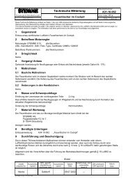
Maintenance Manual STEMME S10 Date of Issue: Oct. 1, 1990 page: 38<br />
7.3.10 Drivetrain System<br />
Adjustment of the Belts on the Transmission Gear:<br />
Amendment No.: 12 Date: Nov 07. 2007<br />
Loosen the clamping screw on the left lower side of the transmission gear. Adjust the belt tension (per belt)<br />
by means of the setting screw on the left transmission gear side to 0.15 in. (3.7 mm) press-down depth<br />
halfway between the axes exerting a press-down force of 11.2 lbf. (50 N). Tighten the clamping screws.<br />
Insufficient belt tension is indicated by slipping together with "squeaking" at full power or when the power<br />
lever is pushed forward suddenly.<br />
Removal:<br />
The propeller shaft can be removed together with transmission gear and the propeller in one step:<br />
− Remove the propeller dome: lift off left and right leg room coverings in the cockpit, Loosen clamping screw<br />
on the stay tube of the propeller dome, pull out locking screw, disconnect flexible hoses, disconnect the<br />
antenna connection to transponder/GPS, withdraw the dome to the front.<br />
− Disconnect the control cable of the propeller brake on the transmission gear.<br />
− Loosen four fastening screws on the transmission gear supports, loosen balancing spring on top of the<br />
transmission gear.<br />
− Pull out transmission gear with propeller shaft.<br />
− The engine side clutch remains on the engine. Removal by loosening of the attachment screws on the<br />
engine flange.<br />
Installation:<br />
− In the opposite order as removal. Attention: Clean and regrease splined sliding joint.<br />
− For tightening moments please refer to section.6.6, page 33.<br />
7.4 Landing Gear<br />
7.4.1 Main Landing Gear<br />
Check the main landing gear legs and the trailing arms for deformation and possible cracks as an result of<br />
overloads.<br />
Adjustment Data: see fig. 3.4.1.a<br />
Functional Check:<br />
Support the aircraft (clearance between the main wheels and the ground must be approximately 1.6 in. / 40<br />
mm), remove upper cowling of the central fuselage.<br />
Checking procedure:<br />
− Inspect screw joints (torque paint);<br />
− check wheels for smooth turning;<br />
− joint heads of the operating arms may not be jammed;<br />
− the articulations of the spindles and the operating arms must have play;<br />
− installation of the landing gear emergency release system without kinks/collisions;<br />
− landing gear stop switches on the operating arms: check for halfway position and proper functioning,<br />
inspect wiring / connection;<br />
A4010022_B12_97.doc-38/04.12.07 16:25/04.12.07 16:30 Doc. No: A40-10-022
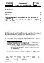
Maintenance Manual STEMME S 10 Date of Issue Oct. 01, 1990 fig. 6.3.a-1<br />
Serial Number:<br />
-<br />
Registration:<br />
-<br />
Amendment No.: 12 Date: Nov. 30. 2007<br />
Relevant Equipment List:<br />
Order No.:<br />
This Weight and Balance Report was drawn up without weighing. Any weighing data have been taken from the<br />
Weight and Balance Report dated and if need be corrected according to point 4.2.<br />
Drawing Up Reason: Conformity Inspection<br />
Changes of Equipment<br />
Repair. Date of Findings Report:<br />
Other:<br />
1. Preparation and Conditions<br />
1.1 The fuselage weight must be determined including rudder, back rests with cushions or equivalent upholstery, seat cushions,<br />
canopy, standard tool kit in baggage compartment behind backrest, Logbook and Flight Manual. Replenish oil if necessary.<br />
Fixed ballast must be installed, loose ballast must be removed.<br />
1.2 Wing weight must be determined with bolts and 3 l / 0.66 imp. gal. fuel (unusable volume).<br />
1.3 Fixed supplementary equipment must be installed.<br />
1.4 Points 1.2 through 1.4 must be observed if an overall weighing of the powered glider is performed. The canopy has to be<br />
closed during weighing.<br />
1.5 If weight and moment arm of additionally installed or removed items is known exactly, the new CG may be determined<br />
numerically (see point 4.2)<br />
2. Overview of Component Weights and Weight Limits<br />
Component Weights from Separate<br />
Weighing<br />
[kg]<br />
[lbs] ***<br />
[kg]<br />
[lbs] ***<br />
Weight Limits [kg]<br />
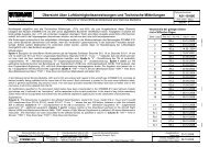
Fig. 6.3.a Mass and Balance Sheet (Pattern; the complete form can be obtained from the<br />
manufacturer)<br />
A4010022_B12_97.doc-1/04.12.07 16:33/05.12.07 08:41 Doc. No: A40-10-022<br />
[lbs] ***<br />
Central Wing Maximum All Up Weight (incl. Fuel) 850 (1874)<br />
Right Hand Outer Wing<br />
Left Hand Outer Wing<br />
Maximum Weight of Non-Lifting Parts<br />
GNTmax (incl. Load in Cockpit)<br />
Of that: Maximum Weight of Equipment on<br />
Instrument Panel, without engine instruments<br />
Fuselage Maximum Load (Max AUW - Empty Weight)<br />
Horizontal Tail<br />
Component Weight Sum<br />
Empty<br />
Weight*<br />
LNT**<br />
Max. Load in Cockpit<br />
(GNTmax - LNT**; maximum 202 kg / 445 lbs,<br />
of that max. 180 kg / 397 lbs in seats, max.<br />
110 kg / 243 lbs in each seat and max. 22 kg<br />
/ 48.5 lbs in baggage compartments)<br />
Cockpit load must be at least 7 kg / 15,43<br />
lbs less than maximum load!<br />
* cross-check: compare with empty weight from 3.; Divergence of 2 kg / 4.4 lbs due to measure error is allowable.<br />
** LNT: Empty weight of "Non Lifting Parts"<br />
*** Units: cross out if not applicable<br />
3. Determining of Empty Weight and Moment Arms<br />
Weights and Moment Arms ***:<br />
forward RH mr kg / lbs<br />
forward LH ml kg / lbs<br />
Tail Wheel ms kg / lbs<br />
Σ=Empty Weight me kg / lbs<br />
Moment Arm a mm / in.<br />
Moment Arm b mm / in.<br />
Datum level: Leading Edge of<br />
Central wing, vertical plane<br />
Pitch: wedge 1000:84 (4°50') on tail<br />
cone, upper edge horizontal<br />
570 (1257)<br />
10<br />
(22)
Maintenance Manual STEMME S 10 Date of Issue Oct. 01, 1990 fig. 6.3.a-2<br />
4. Determining of Empty Weight Center of Gravity<br />
4.1 After Weighing:<br />
x<br />
S<br />
mSb =<br />
m<br />
⋅<br />
+ [mm / in.]*** ⇒ x S =<br />
e<br />
a<br />
4.2 After Changes, without Weighing:<br />
Following changes have been made on the powered glider:<br />
Install. /<br />
Removal<br />
Amendment No.: 12 Date: Nov. 30. 2007<br />
Fig. 6.3.a Mass and Balance Sheet (Pattern; the complete form can be obtained from the<br />
manufacturer)<br />
A4010022_B12_97.doc-0/05.12.07/08:43<br />
Item<br />
⋅<br />
+<br />
Weight ( + /-)<br />
m = [kg / lbs]***<br />
Moment Arm ( + /-)<br />
x = [mm / in.]***<br />
Sum mzus= Sum Mzus=<br />
NOTE: Count weight installed positive, weights removed negative.<br />
Count moment arms aft of datum positive, in front of datum negative.<br />
x<br />
Sneu ,<br />
m ⋅ x + M<br />
=<br />
m<br />
alt alt zus<br />
neu<br />
[mm / in.] ⇒ x S , neu =<br />
5. Definition of Minimum Load Required<br />
⋅ +<br />
With Empty Weight determined: kg / lbs***<br />
and the empty weight CG aft of datum: mm / in. ***<br />
the Minimum Load Required is ****: kg / lbs***<br />
*** Units: cross out if not applicable<br />
****According to Maintenance Manual, Section 6.3<br />
= [mm / in.]***<br />
= mm / in. ***<br />
Site, Date Stamp Sign Job Leader<br />
Moment ( + /-)<br />
M =[mm kg / in. lbs]***<br />
Inspector Statement: All measured data are within the allowable ranges and correspond to the production and<br />
maintenance instructions of the type.<br />
Site, Date Stamp Sign Inspector