for docutech printing - Small Engine Suppliers
for docutech printing - Small Engine Suppliers
for docutech printing - Small Engine Suppliers

Create successful ePaper yourself
Turn your PDF publications into a flip-book with our unique Google optimized e-Paper software.
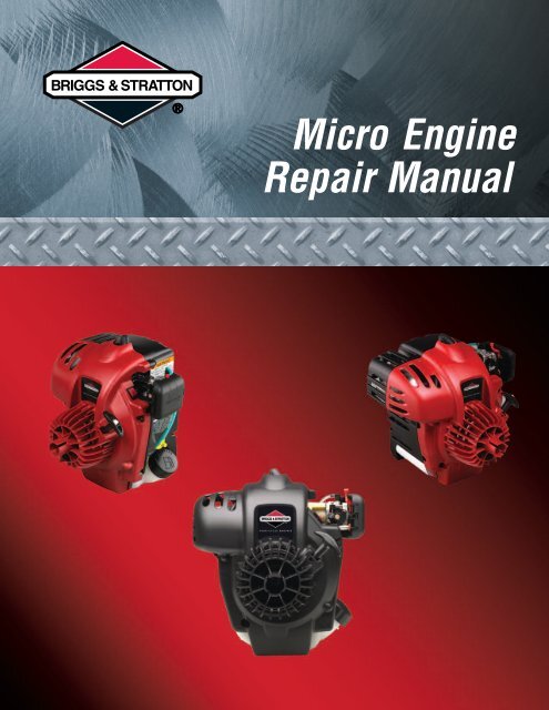
Micro <strong>Engine</strong>Repair Manual
TABLE OF CONTENTSGENERAL INFORMATION . . . . . . . . . . . . . . . . . . . . . . . . . . . . . . . . . . . . . . Section 1DISASSEMBLY AND REPAIR . . . . . . . . . . . . . . . . . . . . . . . . . . . . . . . . . . . Section 2I
SECTION CONTENTS1 Section 1General In<strong>for</strong>mationIn The Interest Of SafetyBriggs & Stratton Numerical Identification System<strong>Engine</strong> IdentificationFuel and Oil RecommendationsGasolineLubricationMaintenanceCheck OilChange OilAir CleanerBreather Check ValveReplace Spark PlugCooling SystemTroubleshootingSystematic CheckCheck IgnitionCheck CarburetionCheck CompressionEquipment Affecting <strong>Engine</strong> OperationHard Starting, Kickback or Will Not StartVibrationPower Loss2 Section 2Disassembly and RepairGeneral In<strong>for</strong>mationRewind AssemblyInspect Starter RopeRemove Blower Housing – Direct Drive <strong>Engine</strong>Replace Starter RopeInstall Blower Housing – Direct Drive <strong>Engine</strong>Remove Blower Housing – Clutch Drive <strong>Engine</strong>Install Blower Housing – Clutch Drive <strong>Engine</strong>Ignition CoilRemove CoilInstall CoilAdjust Air GapFlywheelRemove Flywheel – Direct Drive <strong>Engine</strong>Install Flywheel – Direct Drive <strong>Engine</strong>Remove Flywheel – Clutch Drive <strong>Engine</strong>Install Flywheel – Clutch Drive <strong>Engine</strong>Fuel TankRemove Fuel TankInstall Fuel TankCylinder HeadRemove Cylinder HeadInstall Cylinder HeadMufflerReplace MufflerCarburetorRemove CarburetorInstall CarburetorIdle Speed AdjustmentII
Section 1General In<strong>for</strong>mationSection ContentsIN THE INTEREST OF SAFETY . . . . . . . . . . . . . . . . . . . . . . . . . . . . . . . . . . . . . . . . . . . . . . . . . . . . . . . 1BRIGGS & STRATTON NUMERICAL IDENTIFICATION SYSTEM . . . . . . . . . . . . . . . . . . . . . . . . . 4ENGINE IDENTIFICATION . . . . . . . . . . . . . . . . . . . . . . . . . . . . . . . . . . . . . . . . . . . . . . . . . . . . . . . . . . . . 5FUEL AND OIL RECOMMENDATIONS (Gasoline, Lubrication) . . . . . . . . . . . . . . . . . . . . . . . . . . . . 5MAINTENANCE . . . . . . . . . . . . . . . . . . . . . . . . . . . . . . . . . . . . . . . . . . . . . . . . . . . . . . . . . . . . . . . . . . . . . 6Check Oil . . . . . . . . . . . . . . . . . . . . . . . . . . . . . . . . . . . . . . . . . . . . . . . . . . . . . . . . . . . . . . . . . . . . . . . . . . . . . . . . 6Change Oil . . . . . . . . . . . . . . . . . . . . . . . . . . . . . . . . . . . . . . . . . . . . . . . . . . . . . . . . . . . . . . . . . . . . . . . . . . . . . . . 7Air Cleaner . . . . . . . . . . . . . . . . . . . . . . . . . . . . . . . . . . . . . . . . . . . . . . . . . . . . . . . . . . . . . . . . . . . . . . . . . . . . . . 7Replace Spark Plug . . . . . . . . . . . . . . . . . . . . . . . . . . . . . . . . . . . . . . . . . . . . . . . . . . . . . . . . . . . . . . . . . . . . . . 7Cooling System . . . . . . . . . . . . . . . . . . . . . . . . . . . . . . . . . . . . . . . . . . . . . . . . . . . . . . . . . . . . . . . . . . . . . . . . . . 8TROUBLESHOOTING . . . . . . . . . . . . . . . . . . . . . . . . . . . . . . . . . . . . . . . . . . . . . . . . . . . . . . . . . . . . . . . . 8Systematic Check . . . . . . . . . . . . . . . . . . . . . . . . . . . . . . . . . . . . . . . . . . . . . . . . . . . . . . . . . . . . . . . . . . . . . . . . 8Check Ignition (With <strong>Engine</strong> Starter) . . . . . . . . . . . . . . . . . . . . . . . . . . . . . . . . . . . . . . . . . . . . . . . . . . . . . . . 8Check Ignition (<strong>Engine</strong> Running) . . . . . . . . . . . . . . . . . . . . . . . . . . . . . . . . . . . . . . . . . . . . . . . . . . . . . . . . . . 9Check Carburetion . . . . . . . . . . . . . . . . . . . . . . . . . . . . . . . . . . . . . . . . . . . . . . . . . . . . . . . . . . . . . . . . . . . . . . . 9Check Compression . . . . . . . . . . . . . . . . . . . . . . . . . . . . . . . . . . . . . . . . . . . . . . . . . . . . . . . . . . . . . . . . . . . . . . 9Equipment Affecting <strong>Engine</strong> Operation . . . . . . . . . . . . . . . . . . . . . . . . . . . . . . . . . . . . . . . . . . . . . . . . . . . . 9Hard Starting, Kickback or Will Not Start . . . . . . . . . . . . . . . . . . . . . . . . . . . . . . . . . . . . . . . . . . . . . . . . . . . 9Vibration . . . . . . . . . . . . . . . . . . . . . . . . . . . . . . . . . . . . . . . . . . . . . . . . . . . . . . . . . . . . . . . . . . . . . . . . . . . . . . . 10Power Loss . . . . . . . . . . . . . . . . . . . . . . . . . . . . . . . . . . . . . . . . . . . . . . . . . . . . . . . . . . . . . . . . . . . . . . . . . . . . . 10PageThe Briggs & Stratton engine is made of the finest material in a state-of-the-art manufacturing facility. Please understandthat Briggs & Stratton sells engines to original equipment manufacturers. It also sells to others in thedistribution chain who may sell to the ultimate consumer, an equipment manufacturer, another distributor or adealer. As a result, Briggs & Stratton does not necessarily know the application on which the engine will be placed.For that reason, carefully read and understand the operating instructions of the equipment be<strong>for</strong>e you repair oroperate.You should also understand that there are equipment applications <strong>for</strong> which Briggs & Stratton does not approvethe use of its engines. Briggs & Stratton engines are not to be used on vehicles with less than 4 wheels. Thisincludes motor bikes, aircraft products and All Terrain Vehicles. Moreover, Briggs & Stratton does not approveof its engines being used in competitive events. FOR THAT REASON, BRIGGS & STRATTON ENGINES ARENOT AUTHORIZED FOR ANY OF THESE APPLICATIONS. Failure to follow this warning could result in death,serious injury (including paralysis) or property damage.The safety alert symbol ( ) is used to identifysafety in<strong>for</strong>mation about hazards that can result inpersonal injury.IN THE INTEREST OF SAFETYA signal word (DANGER, WARNING or CAUTION) isused with the alert symbol to indicate the likelihood andthe potential severity of injury. In addition, a hazardsymbol may be used to represent the type of hazard.1
DANGER indicates a hazard which, if notavoided, will result in death or seriousinjury.WARNING indicates a hazard which, ifnot avoided, could result in death orserious injury.The engine exhaust from this productcontains chemicals known to the Stateof Cali<strong>for</strong>nia to cause cancer, birthdefects, or other reproductive harm.WARNINGCAUTION indicates a hazard which, if notavoided, might result in minor ormoderate injury.CAUTION, when used without the alertsymbol, indicates a situation that couldresult in damage to the engine.HAZARD SYMBOLS AND MEANINGSFireToxic FumesHotSurfaceExplosionKickbackMovingPartsShockPrior to work, read and understand the section(s)of this manual that pertain to the job. Follow all safetywarnings.WEAR suitable eye protection (safety glasses,goggles or face shield when per<strong>for</strong>ming repair procedures).PREVENT ACCIDENTAL STARTING by removingspark plug wire from spark plug when servicingengine or equipment.PERIODICALLY clean engine. Keep carburetorparts free of dirt, grass and other debris which canaffect engine speed.USE fresh gasoline. Stale fuel can gum carburetorand cause leakage.CHECK fuel lines and fittings frequently <strong>for</strong> cracksor leaks. Replace if necessary.Gasoline and its vapors are extremelyflammable and explosive.Fire or explosion can cause severe burns ordeath.WHEN ADDING FUEL• Turn engine OFF and let engine cool at least2 minutes be<strong>for</strong>e removing gas cap.• Fill fuel tank outdoors or in well-ventilatedarea.• Do not overfill fuel tank. Fill tank toapproximately 1-1/2 inches below top ofneck to allow <strong>for</strong> fuel expansion.• Keep gasoline away from sparks, openflames, pilot lights, heat, and other ignitionsources.• Check fuel lines, tank, cap, and fittingsfrequently <strong>for</strong> cracks or leaks. Replace ifnecessary.WHEN STARTING ENGINE• Make sure spark plug, muffler, fuel cap andair cleaner are in place.• Do not crank engine with spark plugremoved.• If fuel spills, wait until it evaporates be<strong>for</strong>estarting engine.• If engine floods, set choke to OPEN/RUNposition, place throttle in FAST and crankuntil engine starts.WHEN OPERATING EQUIPMENT• Do not tip engine or equipment at anglewhich causes gasoline to spill.• Do not choke carburetor to stop engine.WHEN STORING GASOLINE OR EQUIP-MENT WITH FUEL IN TANK• Store away from furnaces, stoves, waterheaters or other appliances that have pilotlight or other ignition source because theycan ignite gasoline vapors.2
WARNINGWARNINGUnintentional sparking can result in fire orelectric shock.Unintentional start-up can result in entanglement,traumatic amputation, or laceration.BEFORE PERFORMING ADJUSTMENTSOR REPAIRS• Disconnect spark plug wire and keep it awayfrom spark plug.WHEN TESTING FOR SPARK• Use approved spark plug tester.• Do not check <strong>for</strong> spark with spark plugremoved.WARNINGRunning engines produce heat. <strong>Engine</strong> parts,especially muffler, become extremely hot.Severe thermal burns can occur on contact.Combustible debris, such as leaves, grass,brush, etc. can catch fire.• Allow muffler, engine cylinder and fins to coolbe<strong>for</strong>e touching.• Remove accumulated combustibles frommuffler area and cylinder area.• Install and maintain in working order a sparkarrester be<strong>for</strong>e using equipment on<strong>for</strong>est-covered, grass-covered, brush-coveredunimproved land. The state of Cali<strong>for</strong>niarequires this (Section 4442 of the Cali<strong>for</strong>niaPublic Resources Code). Other states mayhave similar laws. Federal laws apply onfederal land.WARNINGStarting engine creates sparking.Sparking can ignite nearby flammable gases.Explosion and fire could result.• If there is natural or LP gas leakage in area,do not start engine.• Do not use pressurized starting fluidsbecause vapors are flammable.WARNINGRotating parts can contact or entangle hands,feet, hair, clothing, or accessories.Traumatic amputation or severe laceration canresult.• Operate equipment with guards in place.• Keep hands and feet away from rotating parts.• Tie up long hair and remove jewelry.• Do not wear loose-fitting clothing, danglingdrawstrings or items that could becomecaught.WARNING<strong>Engine</strong>s give off carbon monoxide, anodorless, colorless, poison gas.Breathing carbon monoxide can causenausea, fainting or death.• Start and run engine outdoors.• Do not start or run engine in enclosed area,even if doors or windows are open.Rapid retraction of starter cord (kickback) willpull hand and arm toward engine faster thanyou can let go.Broken bones, fractures, bruises or sprainscould result.• When starting engine, pull cord slowly untilresistance is felt, then pull rapidly.• Direct coupled equipment components suchas, but not limited to, blades, impellors,pulleys, sprockets, etc., must be securelyattached.3
YOUR KEY TO THE WORLD’S FINEST ENGINES BRIGGS & STRATTON MODEL NUMBERING SYSTEM YEAR MONTH DAY ASSEMBLY LINE AND MANUFACTURING PLANT01 06 12 014
ENGINE IDENTIFICATION21 67 893511104121. Carburetor2. Stop switch3. Rope handle4. Fuel fill5. Air cleaner6. Choke lever7. Spark plug8. Fuel return hose9. Fuel intake hose10. Primer bulb11. <strong>Engine</strong> Model Type Codexxxxxx xxxx xxxxxxxx12. Oil fill / dipstick13. Fuel tank13FUEL AND OIL RECOMMENDATIONSLubricationGasolineThese engines are certified to operate on unleadedgasoline. Use clean, fresh, regular unleadedgasoline with a minimum of 85 octane. Do not mix oilwith gasoline. Fresh fuel prevents gum from <strong>for</strong>mingin fuel system or on essential carburetor parts.Purchase fuel in quantity that can be used within 30days to assure fuel freshness. We recommend theuse of Briggs & Stratton Gasoline Additive. (Seeyour Authorized Briggs & Stratton Service Dealer<strong>for</strong> Part No. 5041 or the single-use pouch.)In countries other than U.S.A., leaded gasoline maybe used if it is commercially available and unleadedis unavailable.NOTE: Some fuels, called oxygenated or re<strong>for</strong>mulatedgasolines, are gasoline blended withalcohols or ethers. Excessive amounts ofthese blends can damage the fuel system orcause per<strong>for</strong>mance problems. Do not usegasoline containing Methanol. If any undesirableoperating symptoms occur, use gasolinewith a lower percentage of alcohol or ether.Oil has four purposes. It cools, cleans, seals andlubricates. During normal operation, small particlesof metal from the cylinder walls, pistons, bearingsand combustion deposits will gradually contaminatethe oil. Dust particles from the air also contaminatethe oil <strong>for</strong>ming an abrasive mixture which can causewear to all of the internal moving parts of the engine,if the oil is not changed regularly. Fresh oil alsoassists in cooling. Old oil gradually becomes thickand loses its cooling ability as well as its lubricatingqualities.Oil RecommendationsUse a high quality detergent oil classified “For ServiceSF, SG, SH, SJ” or higher. Briggs & Strattonstrongly recommends the use of synthetic oil suchas Briggs & Stratton (#100030C) or equivalent. Ifsynthetic oil is not available, Briggs & Stratton nonsynthetic30 weight oil is an acceptable substitute.No special additives should be used with recommendedoils.Do not mix oil with gasoline.5
SAE VISCOSITY GRADES°F -20 0 20 32 40 60 80 100**°C -30 -20 -10 0 10 20 30 40STARTING TEMPERATURE RANGE ANTICIPATED BEFORE NEXT OILCHANGE* Air cooled engines run hotter thanautomotive engines. Use of non-syntheticmulti-viscosity oils (10W-30, etc.) inambient temperatures above 40° F (4° C)will result in high oil consumption. Ifmulti-viscosity oil is used, check oil levelmore frequently to prevent engine damagedue to lack of lubrication.** SAE 30 oil, if used below 40° F (4° C), willresult in hard starting and possible enginedamage due to inadequate lubrication.Note: Synthetic oil meeting ILSACGF-2, API certification mark andAPI service symbol (shown at left)with “SJ/CF ENERGY CONSERV-ING” or higher, is an acceptable oilat all temperatures. Use of syntheticoil does not alter requiredoil change intervals.Checkoil levelChangeoilServiceairfilterReplacesparkplugMaintenance ScheduleDaily 10HoursorEverySeason**25HoursorEverySeason*50HoursorEverySeason* Change oil after first 4 hours of use, then every8 hours or every season. Change oil every 4 hourswhen operating the engine under heavy load or inhigh temperatures.** Clean more often under dusty conditions or whenairborne debris is present. Replace air cleaner parts,if very dirty.Check Oil1. Place the warm engine with the dipstick facingup. If necessary use a support (2) to level theengine, Fig. 1.NOTE: The engine MUST be level to obtain an accurateoil level measurement.MAINTENANCE2. Unscrew the dipstick (1) and wipe it with a rag.3. Replace the dipstick, thread the dipstick incompletely.4. Unscrew the dipstick to check the oil.WARNINGIf you per<strong>for</strong>m any maintenance on the engine, firstdisconnect the spark plug wire from the spark plugto prevent unintentional sparking. Unintentionalsparking can result in fire or electric shock.Unintentional start-up can result in entanglement,traumatic amputation or laceration. Use onlycorrect tools.Fig. 16
BE SURE OIL LEVEL IS PROPERLYMAINTAINED. Always fill to dipstick FULL mark (1),Fig. 2.Fig. 2Change Oil1. Remove dipstick.2. Invert the engine to drain oil while the engine iswarm.3. Fill engine with 3.0 oz. (88 ml.) of new oil.4. Replace dipstick.Air CleanerA properly serviced air cleaner protects internalparts of the engine from dust particles in the air. Ifair cleaner maintenance instructions are not carefullyfollowed, dirt and dust that should be collectedin the foam filter will be drawn into the engine.Fig. 3Breather Check ValveWith the air cleaner removed inspect the breathercheck valve (1), Fig. 4. Remove any obstructionsfrom the check valve. The check valve should beflexible and remain closed as shown.1. Push cover tab to release air cleaner cover (1),Fig. 3.2. Remove filter (2).3. Wash filter in liquid detergent and water.4. Squeeze it dry in a clean cloth.5. Saturate foam air filter in clean engine oil, thensqueeze out excess oil in clean cloth.6. Install air filter.NOTE: Make sure filter is on outside of locatingbosses and flush with filter base.7. Refer to Breather Check Valve, below.8. Install air cleaner cover.DO NOT use compressed air or solvents to cleanfilter. Compressed air can damage filter; solvents willdissolve filter.Fig. 4Replace Spark PlugReplace spark plug yearly or if electrodes showsigns of wear, or the porcelain is cracked. Set sparkplug gap at .025 inch (.65 mm). Torque spark plug to20 Nm (180 in. lbs.).Briggs & Stratton recommends spark plug number696876 <strong>for</strong> the Micro <strong>Engine</strong>.7
quickest and surest method of determining thecause of failure.Check Ignition (With <strong>Engine</strong> Starter)Cooling System.025” (0.65 mm)Grass particles, chaff or dirt can clog the air coolingsystem. Continued operation with a clogged coolingsystem can cause severe overheating and possibleengine damage. This should be a regular maintenanceoperation, per<strong>for</strong>med yearly. Clean moreoften if necessary.TROUBLESHOOTINGMost complaints concerning engine operation canbe classified as one or a combination of thefollowing:1. Will not start2. Hard Starting3. Lack of power4. Runs Rough5. Vibration6. Overheating7. High Oil ConsumptionNOTE: What appears to be an engine malfunctionmay be a fault of the powered equipmentrather than the engine. If equipment is suspect,see Equipment Affecting <strong>Engine</strong>Operation.Systematic CheckIf the engine is hard starting or will not start andthe cause of malfunction is not readily apparent,per<strong>for</strong>m a systematic check in the following order:1. Ignition2. Carburetion3. CompressionThis check-up, per<strong>for</strong>med in a systematic manner,can usually be done in a matter of minutes. It is theWith stop switch in ON/RUN position and spark pluginstalled, attach a #19368 ignition tester to the sparkplug lead and ground the other end of the tester asshown in Fig. 5. Operate the starter a minimum ofsix times in rapid succession. If a strong, steadyspark is observed at the tester gap, you may assumethe ignition system is functioning satisfactorily.NOTE: If spark initially appears at tester, but stopson subsequent pulls and the stop switch isin the ON/RUN position, check <strong>for</strong> a defectiveequipment stop switch or shorted wires.Fig. 5NOTE: <strong>Engine</strong>s equipped with Magnetron® ignitionsystem will still display spark at tester witha partially or fully sheared flywheel key. Apartially sheared flywheel key will affectignition timing and engine per<strong>for</strong>mance.WARNINGON MAGNETRON® EQUIPPED ENGINES,SPARK CAN STILL OCCUR WITH ASHEARED FLYWHEEL KEY. A SEVERESHOCK OR KICKBACK HAZARD MAY EXIST.8
If spark does not occur look <strong>for</strong> :1. Shorted stop switch2. Shorted ground wire3. Incorrect armature air gap4. Armature failureCheck Ignition(<strong>Engine</strong> Running)If engine runs but misses during operation, a quickcheck to determine if ignition is or is not at fault canbe made by installing Tool #19368 tester betweenthe spark plug lead and spark plug, Fig. 6. A sparkmiss will be readily apparent when the engine isrunning. If spark is good but engine misses, try a newspark plug.Fig. 6Check CarburetionBe<strong>for</strong>e checking carburetion, be sure the fuel tankhas an ample supply of fresh, clean gasoline.Make sure throttle and choke controls are properlyadjusted.If engine cranks but will not start, remove andinspect the spark plug.If plug is wet, look <strong>for</strong>:1. Over choking2. Water in fuel3. Float needle valve stuck open4. Plugged air cleaner5. Fouled spark plugIf plug is dry, look <strong>for</strong>:1. Leaking carburetor mounting gaskets2. Gummy or dirty carburetor, fuel filter, fuel lines orfuel tank3. Float needle valve stuck shut4. Inoperative fuel pumpA simple check to determine if the fuel is getting tothe combustion chamber through the carburetor is toremove the spark plug and pour a small quantity ofgasoline (1 teaspoon or 10 ml.) through the sparkplug hole. Replace the plug. If the engine fires a fewtimes and then stops, look <strong>for</strong> the same conditionsas <strong>for</strong> a dry plug.Check CompressionConnect spark plug wire to long terminal of tester,Tool #19368 and ground tester to engine withalligator clip.To check compression, use a compression tester.Remove the spark plug and install the tester. Crankthe engine using the rewind starter. Continuecranking until meter reading stabilizes. The meterreading should be approximately 50 to 60 P.S.I.(3.5-4 bar) If compression is below 40 P.S.I. (2.8bar), look <strong>for</strong>:1. Loose cylinder head bolts2. Blown head gasket3. Burned valves, valve seats4. Insufficient tappet clearance5. Warped cylinder head6. Warped valve stems7. Worn bore and/or rings8. Broken connecting rodEquipment Affecting <strong>Engine</strong> OperationFrequently, what appears to be a problem withengine operation, such as hard starting, vibration,etc., can be caused by the equipment being poweredrather than the engine itself. Since many variedtypes of equipment are powered by Briggs &Stratton engines, it is not possible to list all of thevarious conditions that may exist. Listed are themost common effects of equipment problems, andwhat to look <strong>for</strong> as the most common cause.Hard Starting, Kickback, or Will Not Start1. Loose blade – blade must be tight to shaft oradaptor. Check <strong>for</strong> partially sheared flywheelkey, or damaged blade and hub.2. Starting under load – see that the unit is notengaged when engine is started; if the unit isengaged, that it does not have a heavyparasitic load.9
3. Check choke or speed control assembly <strong>for</strong>proper adjustment.4. Check interlock system (if equipped) <strong>for</strong> shortedwires, loose or corroded connections, ordefective modules or switches.Vibration1. Cutter blade bent or out of balance – removeand balance.2. Worn blade coupling – replace if coupling allowsblade to shift.3. Mounting bolts loose – tighten.4. Check <strong>for</strong> partially sheared flywheel key.Power LossBind or drag in unit – if possible, disengage engineand operate unit manually to check <strong>for</strong> any bindingaction.10
Section 2Disassembly and RepairSection ContentsGENERAL INFORMATION . . . . . . . . . . . . . . . . . . . . . . . . . . . . . . . . . . . . . . . . . . . . . . . . . . . . . . . . . . . . . . . . . . . 12REWIND ASSEMBLY . . . . . . . . . . . . . . . . . . . . . . . . . . . . . . . . . . . . . . . . . . . . . . . . . . . . . . . . . . . . . . . . . . . . . . . 12Inspect Starter Rope . . . . . . . . . . . . . . . . . . . . . . . . . . . . . . . . . . . . . . . . . . . . . . . . . . . . . . . . . . . . . . . . . . . . . 12Remove Blower Housing – Direct Drive <strong>Engine</strong> . . . . . . . . . . . . . . . . . . . . . . . . . . . . . . . . . . . . . . . . . . . . 12Replace Starter Rope . . . . . . . . . . . . . . . . . . . . . . . . . . . . . . . . . . . . . . . . . . . . . . . . . . . . . . . . . . . . . . . . . . . . 13Install Blower Housing – Direct Drive <strong>Engine</strong> . . . . . . . . . . . . . . . . . . . . . . . . . . . . . . . . . . . . . . . . . . . . . . 13Remove Blower Housing – Clutch Drive <strong>Engine</strong> . . . . . . . . . . . . . . . . . . . . . . . . . . . . . . . . . . . . . . . . . . . 14Install Blower Housing – Clutch Drive <strong>Engine</strong> . . . . . . . . . . . . . . . . . . . . . . . . . . . . . . . . . . . . . . . . . . . . . 14IGNITION COIL . . . . . . . . . . . . . . . . . . . . . . . . . . . . . . . . . . . . . . . . . . . . . . . . . . . . . . . . . . . . . . . . . . . . 16Remove Coil . . . . . . . . . . . . . . . . . . . . . . . . . . . . . . . . . . . . . . . . . . . . . . . . . . . . . . . . . . . . . . . . . . . . . . . . . . . 16Install Coil . . . . . . . . . . . . . . . . . . . . . . . . . . . . . . . . . . . . . . . . . . . . . . . . . . . . . . . . . . . . . . . . . . . . . . . . . . . . . 16Adjust Air Gap . . . . . . . . . . . . . . . . . . . . . . . . . . . . . . . . . . . . . . . . . . . . . . . . . . . . . . . . . . . . . . . . . . . . . . . . . . 16FLYWHEEL . . . . . . . . . . . . . . . . . . . . . . . . . . . . . . . . . . . . . . . . . . . . . . . . . . . . . . . . . . . . . . . . . . . . . . . . 17Remove Flywheel – Direct Drive <strong>Engine</strong> . . . . . . . . . . . . . . . . . . . . . . . . . . . . . . . . . . . . . . . . . . . . . . . . . . . 17Install Flywheel – Direct Drive <strong>Engine</strong> . . . . . . . . . . . . . . . . . . . . . . . . . . . . . . . . . . . . . . . . . . . . . . . . . . . . . 17Remove Flywheel – Clutch Drive <strong>Engine</strong> . . . . . . . . . . . . . . . . . . . . . . . . . . . . . . . . . . . . . . . . . . . . . . . . . . 17Install Flywheel – Clutch Drive <strong>Engine</strong> . . . . . . . . . . . . . . . . . . . . . . . . . . . . . . . . . . . . . . . . . . . . . . . . . . . . 18FUEL TANK . . . . . . . . . . . . . . . . . . . . . . . . . . . . . . . . . . . . . . . . . . . . . . . . . . . . . . . . . . . . . . . . . . . . . . . . 18Remove Fuel Tank . . . . . . . . . . . . . . . . . . . . . . . . . . . . . . . . . . . . . . . . . . . . . . . . . . . . . . . . . . . . . . . . . . . . . . . 18Install Fuel Tank . . . . . . . . . . . . . . . . . . . . . . . . . . . . . . . . . . . . . . . . . . . . . . . . . . . . . . . . . . . . . . . . . . . . . . . . . 18CYLINDER HEAD . . . . . . . . . . . . . . . . . . . . . . . . . . . . . . . . . . . . . . . . . . . . . . . . . . . . . . . . . . . . . . . . . . . 19Remove Cylinder Head . . . . . . . . . . . . . . . . . . . . . . . . . . . . . . . . . . . . . . . . . . . . . . . . . . . . . . . . . . . . . . . . . . 19Install Cylinder Head . . . . . . . . . . . . . . . . . . . . . . . . . . . . . . . . . . . . . . . . . . . . . . . . . . . . . . . . . . . . . . . . . . . . 19MUFFLER . . . . . . . . . . . . . . . . . . . . . . . . . . . . . . . . . . . . . . . . . . . . . . . . . . . . . . . . . . . . . . . . . . . . . . . . . 19Replace Muffler . . . . . . . . . . . . . . . . . . . . . . . . . . . . . . . . . . . . . . . . . . . . . . . . . . . . . . . . . . . . . . . . . . . . . . . . . 19CARBURETOR . . . . . . . . . . . . . . . . . . . . . . . . . . . . . . . . . . . . . . . . . . . . . . . . . . . . . . . . . . . . . . . . . . . . . 20Remove Carburetor . . . . . . . . . . . . . . . . . . . . . . . . . . . . . . . . . . . . . . . . . . . . . . . . . . . . . . . . . . . . . . . . . . . . . . 20Install Carburetor . . . . . . . . . . . . . . . . . . . . . . . . . . . . . . . . . . . . . . . . . . . . . . . . . . . . . . . . . . . . . . . . . . . . . . . 20Idle Speed Adjustment . . . . . . . . . . . . . . . . . . . . . . . . . . . . . . . . . . . . . . . . . . . . . . . . . . . . . . . . . . . . . . . . . . . 21Page11
GENERAL INFORMATIONThe extent of service to the Micro <strong>Engine</strong> is limited to the replacement of the major external components of theengine. The Section Contents lists the serviceable components in the required sequence of disassembly. Forexample, to replace the ignition coil it would be necessary to remove the blower housing. There<strong>for</strong>e the rewindremoval procedure is listed first. With the blower housing removed the ignition coil, flywheel and fuel tank areaccessible. To replace the muffler the blower housing and cylinder shield must be removed.NOTE: When removing screws from the engine, the screw threads will loosen aluminum particles which can getinto the engine:Clean thoroughly whenever removing screws from the engine.Do not use impact tools to remove or install screws.Use lubricant liberally whenever removing screws.NOTE: There is no provision to bore or hone the engine block. If the piston bore is worn or damaged, replacethe engine.REWIND ASSEMBLYInspect Starter Rope1. Pull starter rope out and hold.2. Inspect starter rope. Replace the rope if anystrands are frayed or broken.To service the blower housing/rewind assembly theengine must be removed from the piece ofequipment.The starter rewind pulley and spring are notserviceable. If pulley is damaged or spring is brokenthe blower housing/rewind assembly must bereplaced.Fig. 1Remove Blower Housing – Direct Drive <strong>Engine</strong>Remove screws with the T-25 bit from Briggs &Stratton Tool #19442 Torqux Star Bit Set.1. Remove 2 screws (1) from blower housing Fig. 1.2. Remove 4 screws (2) from cylinder shield side,Fig. 2.3. Remove blower housing.Fig. 212
Replace Starter Rope1. Pull rope out part way and tie a temporary knot.2. Remove rope from rope handle and untie knot,Fig. 3.3. Remove starter handle.Fig. 411. Pull rope until knot is seated in pulley.12. Then let rope rewind into starter.13. Operate starter to check <strong>for</strong> smooth operation.Fig. 34. Pull rope out as far as it will go and untietemporary knot.5. While holding rewind pulley, grasp knot in pulleywith a pair of needle nose pliers and pull rope outof pulley.6. Slowly release spring tension on pulley untilpulley stops turning.NOTE: Replacement rope has handle attached.7. Rotate pulley CLOCKWISE, SEVEN (7)complete turns.8. Then rotate pulley counterclockwise until ropehole in pulley is in line with starter housingeyelet. Hold pulley in this position.Install Blower Housing – Direct Drive <strong>Engine</strong>Assemble blower housing to engine.NOTE: Be sure stop switch is installed in its notchin blower housing.1. Install 4 screws (2) from cylinder shield side,Fig. 5.Torque screws to 25 in. lbs. (3 Nm).9. Insert rope through eyelet in housing and thenthrough hole in pulley (1), Fig. 4.10. Tie a figure eight knot in end of rope (2), asshown.Fig. 513
2. Install 2 screws in blower housing, Fig. 6.Torque screws to 40 in. lbs. (5 Nm).Fig. 83. Remove clutch (1) and thrust washer (2), Fig. 9.Fig. 6Remove Blower Housing – Clutch Drive <strong>Engine</strong>Be<strong>for</strong>e the blower housing can be removed it isnecessary to remove the clutch assembly.1. Remove 6 screws (1) and clutch housing cover,Fig. 7.Fig. 94. Remove 2 screws (1) from blower housing,Fig. 10.Fig. 72. Remove clutch drum (1) using T 15 bit fromBriggs & Stratton Tool #19442 Torqux Star BitSet, Fig. 8.NOTE: Clutch drum mounting screw remainscaptive in clutch drum.Fig. 1014
5. Remove 4 screws (2) from cylinder shield side,Fig. 11.6. Remove blower housing.Fig. 117. Check ball bearing <strong>for</strong> rough spots or excessivelooseness (wear).a. If bearing is bad the blower housing must bereplaced.Starter rope inspection and replacement procedureis the same as direct drive engine.Fig. 133. Install thrust washer (1), Fig. 14.4. Assemble clutch to shaft with writing up (2).Hand tighten clutch.5. Assemble clutch drum to engine, Fig. 15.Torque screw to 20 in. lbs. (2.0 Nm).Install Blower Housing – Clutch Drive <strong>Engine</strong>Place a drop of engine oil on ball bearing journal onflywheel nut/crank adapter.Assemble blower housing to engine.NOTE: Be sure stop switch wires are routedthrough blower housing.1. Install 4 screws (2) from cylinder shield side,Fig. 12.Torque screws to 25 in. lbs. (3 Nm).Fig. 14Fig. 122. Install 2 screws in blower housing, Fig. 13.Torque screws to 40 in. lbs. (5 Nm).Fig. 1515
6. Assemble clutch housing cover to blowerhousing.NOTE: Raised boss (1) on clutch housing covermust fit in recessed boss (2) on blowerhousing, Fig. 16.Torque screws to 20 in. lbs. (5.0 Nm).2. Install coil. Install stop switch wires.NOTE: Route stop switch wires behind spark plugwire and then over spark plug as shown,Fig. 18.3. Pull coil up as far as it will go and temporarilytighten screws.IGNITION COILFig. 16Remove CoilUse the T-25 driver.1. Disconnect stop switch wire (1).2. Remove 2 screws (2) and ignition coil withground wire, Fig. 17.Fig. 18Adjust Air Gap1. Rotate flywheel so that magnets are under armature.2. Insert feeler gage .010” – .014” (.25 – .35 mm)between flywheel magnets and armature,Fig. 19.3. Loosen coil mounting screws so magnet pullscoil down to feeler gage.4. Torque screws to 60 in. lbs.5. Remove feeler gage.Fig. 17Install Coil1. Rotate flywheel so that magnets are away fromcoil.Fig. 1916
FLYWHEELRemove Flywheel – Direct Drive <strong>Engine</strong>Remove the ignition coil.1. Install flywheel puller Tool #19538 (1) with theconcave side down.2. Rotate puller so that it is under the starterpawls (2).3. Insert the driver in to flywheel nut /crank adapter(3).4. Secure flywheel with strap wrench Tool #19433.5. Turn driver counterclockwise to loosen flywheelnut/crank adapter, Fig. 20.6. Continue turning until flywheel loosens.Fig. 21Install Flywheel – Direct Drive <strong>Engine</strong>Align flywheel key with keyway in crankshaft andinstall flywheel.1. Secure flywheel with strap wrench Tool #19433.2. Install flywheel nut/crank adapter and insertdriver into flywheel nut/crank adapter.3. Torque to 170 in. lbs. (19 Nm), Fig. 22.Fig. 20Fig. 224. Install ignition coil.NOTE: The flywheel key is part of the flywheelcasting.Check the key (1) <strong>for</strong> damage. If key is damaged orsheared the flywheel must be replaced, Fig. 21.Remove Flywheel – Clutch Drive <strong>Engine</strong>Remove the ignition coil.1. Secure flywheel with strap wrench Tool #19433.2. Loosen flywheel nut/crank adapter (1) with 9/16”wrench, Fig. 23. Then remove.17
FUEL TANKThe fuel tank and fuel lines are serviced as anassembly.Remove Fuel TankDrain fuel tank.1. Disconnect fuel lines at carburetor.2. Remove fuel tank, Fig. 25.3. Remove rubber tank supports (1).4. Remove heat shield (2).Fig. 233. Thread flywheel nut/tool (1) from Tool #19538 onto crankshaft, Fig. 24.Fig. 25Fig. 244. Install flywheel puller Tool #19538 with the concaveside down.5. Rotate puller so that it is under the starter pawls.6. Insert the driver in to flywheel nut.7. Secure flywheel with strap wrench Tool #19433.8. Turn driver until flywheel loosens.Check the key <strong>for</strong> damage. If key is damaged orsheared the flywheel must be replaced.Install Flywheel – Clutch Drive <strong>Engine</strong>Align flywheel key with keyway in crankshaft andinstall flywheel.1. Secure flywheel with strap wrench Tool #19433.2. Install flywheel nut/crank adapter and torque to170 in. lbs. (19 Nm).Install Fuel Tank1. Install heat shield and rubber tank supports.2. Insert tank in to pocket in cylinder shield.3. Install fuel supply line (1) and fuel return line (2),Fig. 26.NOTE: Fuel line is colored. Fuel return line is clear.Fig. 2618
CYLINDER HEADNOTE: Valves and seats are not serviceable.Remove Cylinder HeadRemove the flywheel and ignition coil.1. Remove 2 screws (1) and cylinder shield, Fig.27.Use the T-25 driver.Install Cylinder Head1. Install cylinder head with new gasket.2. Torque head bolts in sequence shown to 75 in.lbs. (8.5 Nm), Fig. 29.Fig. 29MUFFLERFig. 272. Remove 7 cylinder head bolts (2), Fig. 28.3. Remove cylinder head and discard gasket.NOTE: With the cylinder head removed, check thecylinder bore. If the bore is worn or scoredthe engine must be replaced.Replace MufflerUse the T-25 driver.1. Remove the top 3 muffler bolts (1), Fig. 30. Removemuffler. Discard gasket.Fig. 30Fig. 282. Install muffler with new gasket. Torque screws to60 in. lbs.19
3. Install cylinder shield. Torque screws (1) to 40 in.lbs. (5 Nm), Fig. 31.6. Remove and discard the old mounting gasket.Install Carburetor1. Install new mounting gasket.Make sure pulse hole in gasket (1) is aligned withpulse channel (2) in carburetor spacer, Fig. 33.Fig. 31CARBURETORThe carburetor is serviced as an assembly.Remove CarburetorDrain fuel tank.1. Disconnect fuel lines at carburetor.2. Remove air cleaner cover and filter.3. Remove 2 nuts (1), Fig. 32.4. Remove air cleaner base.5. Slide carburetor from studs.Fig. 332. Slide carburetor on to studs, Fig. 34.NOTE: Make sure O-ring (1) is assembled tocarburetor.Fig. 32Fig. 3420
3. Install air cleaner base.4. Insert breather check valve (1) through aircleaner base. Make sure slot in breather valve isin a vertical position as shown, Fig. 35.5. Install nuts (2).a. Torque nuts to 25 in. lbs. (3 Nm).Fig. 35Fig. 36Idle Speed AdjustmentNOTE: Correct adjustment is necessary to obtainproper acceleration and clutch disengagementon clutch drive engines1. Start engine and warm up approximately 5minutes be<strong>for</strong>e adjusting.2. Make surer throttle lever is contacting idleadjustment screw (1), Fig. 37.3. Adjust idle speed to:3600 RPM – Clutch Drive <strong>Engine</strong>4000 RPM – Direct Drive <strong>Engine</strong>6. Install fuel supply line (1) and fuel return line (2),Fig. 36.7. Assemble throttle cable to carburetor.8. Assemble air cleaner.Fig. 3721
Cylinder BorePiston Ring End Gap – Top RingPiston Ring End Gap – Second RingPiston Ring End Gap – Oil Control RingsSpark Plug GapSPECIFICATIONSMicro <strong>Engine</strong> DimensionsMicro <strong>Engine</strong> Torque Specifications1.575 in. (40.00 mm).004 – .011 in. (.10 – .28 mm).004 – .011 in. (.10 – .28 mm).008 – .027 in. (.20 – .69 mm).022 – .028 in. (.56 – .71 mm)Fastener LocationQuantityUsedTorqueInch PoundsTorqueNewton MetersBlower Housing 2 40 5Camshaft Cover 2 50 6Carb Adapter 2 60 7Carb Mount Stud 2 25 3Clutch Drum 1 20 2Cylinder Head 7 75 8Cylinder Shield to Blower Housing 4 25 3Cylinder Shield(Rear Housing)2 40 5Flywheel Nut/ Crank Adapter 1 170 19Ignition Coil 2 60 7Muffler Deflector 2 40 5Muffler 3 60 7Spark Plug #696876 1 180 20Sump Cover 9 60 7Valve Cover 2 60 722
Repair Manuals <strong>for</strong> otherBriggs & Stratton <strong>Engine</strong>s, order:CE8069 – Out of Production <strong>Engine</strong>s (From 1919-1981)270962 – Single Cylinder “L” Head (Built after 1981)271172 – Twin Cylinder “L” Head272144 – Vanguard V-Twin OHV272147 – Single Cylinder OHV273521 – Intek V-Twin Cylinder OHV275110 – OutboardMS-0729 – 3 Cylinder Liquid Cooled®Quality Starts With AMaster Service TechnicianBRIGGS & STRATTON CORPORATIONMilwaukee,WI 53201Part No. 275072-12/03 Printed in U.S.A.www.briggsandstratton.com