parameter identification of the lead-acid battery model
parameter identification of the lead-acid battery model
parameter identification of the lead-acid battery model

You also want an ePaper? Increase the reach of your titles
YUMPU automatically turns print PDFs into web optimized ePapers that Google loves.
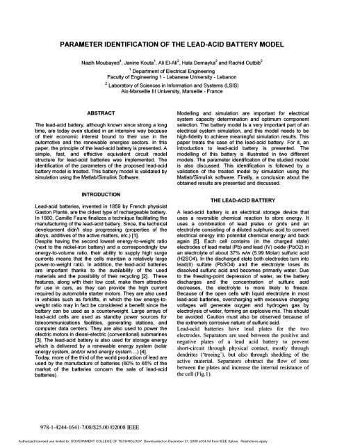
PARAMETER IDENTIFICATION OF THE LEAD-ACID BATTERY MODELNazih Moubayed 1 , Janine Kouta 1 , Ali EI-AIi 2 , Hala Dernayka 2 and Rachid Outbib 21 Department <strong>of</strong> Electrical EngineeringFaculty <strong>of</strong> Engineering 1 - Lebanese University - Lebanon2 Laboratory <strong>of</strong> Sciences in Information and Systems (LSIS)Aix-Marseille III University, Marseille - FranceABSTRACTThe <strong>lead</strong>-<strong>acid</strong> <strong>battery</strong>, although known since strong a longtime, are today even studied in an intensive way because<strong>of</strong> <strong>the</strong>ir economic interest bound to <strong>the</strong>ir use in <strong>the</strong>automotive and <strong>the</strong> renewable energies sectors. In thispaper, <strong>the</strong> principle <strong>of</strong> <strong>the</strong> <strong>lead</strong>-<strong>acid</strong> <strong>battery</strong> is presented. Asimple, fast, and effective equivalent circuit <strong>model</strong>structure for <strong>lead</strong>-<strong>acid</strong> batteries was implemented. The<strong>identification</strong> <strong>of</strong> <strong>the</strong> <strong>parameter</strong>s <strong>of</strong> <strong>the</strong> proposed <strong>lead</strong>-<strong>acid</strong><strong>battery</strong> <strong>model</strong> is treated. This <strong>battery</strong> <strong>model</strong> is validated bysimulation using <strong>the</strong> Matlab/Simulink S<strong>of</strong>tware.INTRODUCTIONLead-<strong>acid</strong> batteries, invented in 1859 by French physicistGaston Plante, are <strong>the</strong> oldest type <strong>of</strong> rechargeable <strong>battery</strong>.In 1880, Camille Faure finalizes a technique facilitating <strong>the</strong>manufacturing <strong>of</strong> <strong>the</strong> <strong>lead</strong>-<strong>acid</strong> <strong>battery</strong>. Since, <strong>the</strong> technicaldevelopment didn't stop progressing (properties <strong>of</strong> <strong>the</strong>alloys, additives <strong>of</strong> <strong>the</strong> active matters, etc.) [1).Despite having <strong>the</strong> second lowest energy-to-weight ratio(next to <strong>the</strong> nickel-iron <strong>battery</strong>) and a correspondingly lowenergy-to-volume ratio, <strong>the</strong>ir ability to supply high surgecurrents means that <strong>the</strong> cells maintain a relatively largepower-to-weight ratio. In addition, <strong>the</strong> <strong>lead</strong>-<strong>acid</strong> batteriesare important thanks to <strong>the</strong> availability <strong>of</strong> <strong>the</strong> usedmaterials and <strong>the</strong> possibility <strong>of</strong> <strong>the</strong>ir recycling [2). Thesefeatures, along with <strong>the</strong>ir low cost, make <strong>the</strong>m attractivefor use in cars, as <strong>the</strong>y can provide <strong>the</strong> high currentrequired by automobile starter motors. They are also usedin vehicles such as forklifts, in which <strong>the</strong> low energy-toweightratio may in fact be considered a benefit since <strong>the</strong><strong>battery</strong> can be used as a counterweight. Large arrays <strong>of</strong><strong>lead</strong>-<strong>acid</strong> cells are used as standby power sources fortelecommunications facilities, generating stations, andcomputer data centers. They are also used to power <strong>the</strong>electric motors in diesel-electric (conventional) submarines[3). The <strong>lead</strong>-<strong>acid</strong> <strong>battery</strong> is also used for storage energywhich is delivered by a renewable energy system (solarenergy system, and/or wind energy system .... ) [4).Today, more <strong>of</strong> <strong>the</strong> third <strong>of</strong> <strong>the</strong> world production <strong>of</strong> <strong>lead</strong> areused by <strong>the</strong> manufacture <strong>of</strong> batteries (60% to 65% <strong>of</strong> <strong>the</strong>market <strong>of</strong> <strong>the</strong> batteries concern <strong>the</strong> sale <strong>of</strong> <strong>lead</strong>-<strong>acid</strong>batteries).Modelling and simulation are important for electricalsystem capacity determination and optimum componentselection. The <strong>battery</strong> <strong>model</strong> is a very important part <strong>of</strong> anelectrical system simulation, and this <strong>model</strong> needs to behigh-fidelity to achieve meaningful simulation results. Thispaper treats <strong>the</strong> case <strong>of</strong> <strong>the</strong> <strong>lead</strong>-<strong>acid</strong> <strong>battery</strong>. For it, anintroduction to <strong>lead</strong>-<strong>acid</strong> <strong>battery</strong> is presented. The<strong>model</strong>ling <strong>of</strong> this <strong>battery</strong> is illustrated in two different<strong>model</strong>s. The <strong>parameter</strong> <strong>identification</strong> <strong>of</strong> <strong>the</strong> studied <strong>model</strong>is also discussed. This <strong>identification</strong> is followed by avalidation <strong>of</strong> <strong>the</strong> treated <strong>model</strong> by simulation using <strong>the</strong>Matlab/Simulink s<strong>of</strong>tware. Finally, a conclusion about <strong>the</strong>obtained results are presented and discussed.THE LEAD-ACID BATTERYA <strong>lead</strong>-<strong>acid</strong> <strong>battery</strong> is an electrical storage device thatuses a reversible chemical reaction to store energy. Ituses a combination <strong>of</strong> <strong>lead</strong> plates or grids and anelectrolyte consisting <strong>of</strong> a diluted sulphuric <strong>acid</strong> to convertelectrical energy into potential chemical energy and backagain [5). Each cell contains (in <strong>the</strong> charged state)electrodes <strong>of</strong> <strong>lead</strong> metal (Pb) and <strong>lead</strong> (IV) oxide (Pb02) inan electrolyte <strong>of</strong> about 37% wlw (5.99 Molar) sulfuric <strong>acid</strong>(H2S04). In <strong>the</strong> discharged state both electrodes tum into<strong>lead</strong>(lI) sulfate (PbS04) and <strong>the</strong> electrolyte loses itsdissolved sulfuric <strong>acid</strong> and becomes primarily water. Dueto <strong>the</strong> freezing-point depression <strong>of</strong> water, as <strong>the</strong> <strong>battery</strong>discharges and <strong>the</strong> concentration <strong>of</strong> sulfuric <strong>acid</strong>decreases, <strong>the</strong> electrolyte is more likely to freeze.Because <strong>of</strong> <strong>the</strong> open cells with liquid electrolyte in most<strong>lead</strong>-<strong>acid</strong> batteries, overcharging with excessive chargingvoltages will generate oxygen and hydrogen gas byelectrolysis <strong>of</strong> water, forming an explosive mix. This shouldbe avoided. Caution must also be observed because <strong>of</strong><strong>the</strong> extremely corrosive nature <strong>of</strong> sulfuric <strong>acid</strong>.Lead-<strong>acid</strong> batteries have <strong>lead</strong> plates for <strong>the</strong> twoelectrodes. Separators are used between <strong>the</strong> positive andnegative plates <strong>of</strong> a <strong>lead</strong> <strong>acid</strong> <strong>battery</strong> to preventshort-circuit through physical contact, mostly throughdendrites ('treeing'), but also through shedding <strong>of</strong> <strong>the</strong>active material. Separators obstruct <strong>the</strong> flow <strong>of</strong> ionsbetween <strong>the</strong> plates and increase <strong>the</strong> internal resistance <strong>of</strong><strong>the</strong> cell (Fig. 1).978-1-4244-1641-7/08/$25.00 ©2008 IEEEAuthorized licensed use limited to: GOVERNMENT COLLEGE OF TECHNOLOGY. Downloaded on December 31, 2009 at 04:54 from IEEE Xplore. Restrictions apply.
tLI.&&~I- -('I Reec\a"";lhReacts IoI1th0 sulfuric ootd sulfate ;ons.c .c"'form 1 .... to form loade.e. s ulfato. Must sulfate. Pbs uppl y .lootronssupplios Iwend 10 Ionposlt1vepositive H 2SO 4 chergno end1 .... eloctrode""--- H2O 1. left ""---IIOQ8tiveFigure 1: Lead-<strong>acid</strong> <strong>battery</strong> [6].MODELING OF THE LEAD-ACID BATTERYThe <strong>lead</strong>-<strong>acid</strong> <strong>battery</strong> represents a fundamental and mainelement in <strong>the</strong> renewable energy systems and in <strong>the</strong>hybrid vehicles. Therefore, it is necessary to study <strong>the</strong><strong>model</strong>ing <strong>of</strong> this type <strong>of</strong> batteries. In fact, very bigquantities <strong>of</strong> <strong>model</strong>s exist, from <strong>the</strong> simplest, containingimpedance placed in series with a voltage source, to <strong>the</strong>most complex. In general, <strong>the</strong>se <strong>model</strong>s represent <strong>the</strong><strong>battery</strong> like an electric circuit composed <strong>of</strong> resistances,capacities and o<strong>the</strong>r elements, constant or variable(function <strong>of</strong> <strong>the</strong> temperature or <strong>the</strong> State Of Charge SOCthat gives an idea on <strong>the</strong> quantity <strong>of</strong> active substance)[7],[8].The simplified <strong>model</strong>The simplest <strong>model</strong> <strong>of</strong> a <strong>lead</strong>-<strong>acid</strong> <strong>battery</strong> is composed <strong>of</strong>a voltage source placed in series with impedance (Fig. 2).,...Lr------Figure 2: Lead-<strong>acid</strong> <strong>battery</strong> simplest <strong>model</strong>.The main problem <strong>of</strong> this <strong>model</strong> is that <strong>the</strong> two elementsE(p) and Z(p) must be at least function <strong>of</strong> <strong>the</strong> State OfCharge (SOC) and <strong>of</strong> <strong>the</strong> <strong>battery</strong>'s temperature e [9,10].The improvement <strong>of</strong> <strong>the</strong> simple <strong>model</strong> takes place whi<strong>lead</strong>ding a parasitic branch in parallel (Figure 3).I,... (C1SOC')Figure 3: Lead-<strong>acid</strong> <strong>battery</strong> general <strong>model</strong>.In fact, <strong>the</strong> parasitic branch represents <strong>the</strong> irreversiblereactions that take place in <strong>the</strong> <strong>battery</strong> as for example <strong>the</strong>electrolysis <strong>of</strong> water that occurs at <strong>the</strong> end <strong>of</strong> <strong>the</strong> chargingprocess, especially in <strong>the</strong> case <strong>of</strong> overcharge. In thisbranch an Ip current circulates. The charge stocked in <strong>the</strong><strong>battery</strong> is only joined to 1m (current <strong>of</strong> <strong>the</strong> main branch, inamperes). A part <strong>of</strong> <strong>the</strong> total current I, which is <strong>the</strong> Ipcurrent, is a lost current and cannot be restored.The third order <strong>model</strong> [11]The <strong>model</strong> is consisted <strong>of</strong> two main parts: a main branchwhich approximated <strong>the</strong> <strong>battery</strong> dynamics under mostconditions, and a parasitic branch which accounted for <strong>the</strong><strong>battery</strong> behavior at <strong>the</strong> end <strong>of</strong> a charge. The main branchis formed <strong>of</strong> a R/C block placed in series with a resistance(Figure 4). All elements <strong>of</strong> figure 4 are functions <strong>of</strong> <strong>the</strong>State Of Charge (SOC), <strong>the</strong> charging/discharging currentsand <strong>the</strong> temperature <strong>of</strong> <strong>the</strong> electrolyte 9.EmNFigure 4: Lead-<strong>acid</strong> <strong>battery</strong> third order <strong>model</strong>.where:• Em was <strong>the</strong> main branch voltage,• R1 was <strong>the</strong> main branch resistance,• C1 was <strong>the</strong> main branch capacitance,• R2 was <strong>the</strong> main branch resistance,• I 01pn) was <strong>the</strong> Parasitic branch current,• Ro was <strong>the</strong> Terminal resistance.RO,...L+Main branch voltage (Em)Equation 1 approximated <strong>the</strong> internal electro-motive force(emf), or open-circuit voltage <strong>of</strong> one cell. The emf valuewas assumed to be constant when <strong>the</strong> <strong>battery</strong> was fullycharged. The emf varied with temperature and state <strong>of</strong>charge (SOC):Em = EmO - KE .(273 + 9)(1-SOC) (1)where:• Em was <strong>the</strong> open-circuit voltage (EMF) in volts,• Emo was <strong>the</strong> open-circuit voltage at full charge in volts,• KE was a constant in volts 1 DC,• 9 was electrolyte temperature in DC,• SOC was <strong>battery</strong> state <strong>of</strong> charge.Main branch resistance R1Equation 2 approximated a resistance in <strong>the</strong> main branch<strong>of</strong> <strong>the</strong> <strong>battery</strong>. The resistance varied with depth <strong>of</strong> charge,a measure <strong>of</strong> <strong>the</strong> <strong>battery</strong>'s charge adjusted for <strong>the</strong>discharge current. The resistance increased exponentiallyas <strong>the</strong> <strong>battery</strong> became exhausted during a discharge.v978-1-4244-1641-7/08/$25.00 ©2008 IEEEAuthorized licensed use limited to: GOVERNMENT COLLEGE OF TECHNOLOGY. Downloaded on December 31, 2009 at 04:54 from IEEE Xplore. Restrictions apply.
where:• R1 was a main branch resistance in Ohms,• R10 was a constant in Ohms,• DOC was <strong>battery</strong> depth <strong>of</strong> charge.(2)Main branch capacitance C1Equation 3 approximated a capacitance (or time delay) in<strong>the</strong> main branch. The time constant <strong>model</strong>ed a voltagedelay when <strong>battery</strong> current changed.C 1 =l (3)RIwhere:• C1 was a main branch capacitance in Farads,• T1 was a main branch time constant in seconds,• R1 was a main branch resistance in Ohms.Main branch resistance R2Equation 4 approximated a main branch resistance. Theresistance increased exponentially as <strong>the</strong> <strong>battery</strong> state <strong>of</strong>charge increased.The resistance also varied with <strong>the</strong> current flowing through<strong>the</strong> main branch. The resistance primarily affected <strong>the</strong><strong>battery</strong> during charging. The resistance became relativelyinsignificant for discharge currents:Note that while <strong>the</strong> constant Gpo was measured in units <strong>of</strong>seconds, <strong>the</strong> magnitude <strong>of</strong> Gpo was very small, on <strong>the</strong>order <strong>of</strong> 10-12 seconds.I p =V PN. G po·exp + p (6)VpoSf[VPN /(t p .s+l) A (1-~)lwhere:• Ip was <strong>the</strong> current loss in <strong>the</strong> parasitic branch,• VPN was <strong>the</strong> voltage at <strong>the</strong> parasitic branch,• GpO was a constant in seconds,• Tp was a parasitic branch time constant in seconds,• Vpo was a constant in volts,• Ap was a constant,• 8 was <strong>the</strong> electrolyte temperature in DC,• 8t was <strong>the</strong> electrolyte freezing temperature in DC.Some definitionsExtracted charge QeEquation 7 tracked <strong>the</strong> amount <strong>of</strong> charge extracted from<strong>the</strong> <strong>battery</strong>. The charge extracted from <strong>the</strong> <strong>battery</strong> was asimple integration <strong>of</strong> <strong>the</strong> current flowing into or out <strong>of</strong> <strong>the</strong>main branch. The initial value <strong>of</strong> extracted charge wasnecessary for simulation purposes.tQe(t) = Qe_init + f-Im(t).dt(7)owhere:• R2 was a main branch resistance in Ohms,• R20 was a constant in Ohms,• A21 was a constant,• A22 was a constant,• Em was <strong>the</strong> open-circuit voltage (EMF) in volts,• SOC was <strong>the</strong> <strong>battery</strong> state <strong>of</strong> charge,• 1m was <strong>the</strong> main branch current in Amps,• 1* was <strong>the</strong> nominal <strong>battery</strong> current in Amps.(4)Total capacity CEquation 8 approximated <strong>the</strong> capacity <strong>of</strong> <strong>the</strong> <strong>battery</strong> basedon discharge current and electrolyte temperature.However, <strong>the</strong> capacity dependence on current was only fordischarge. During charge, <strong>the</strong> discharge current was setequal to zero in Equation 8 for <strong>the</strong> purposes <strong>of</strong> calculatingtotal capacity.C(I,9) = K,.C,' , {l-~)'1+(Kc-l~I~) Sf(8)Terminal resistance ROEquation 5 approximated a resistanceseen at <strong>the</strong> <strong>battery</strong>terminals. The resistance was assumed constant at alltemperatures, and varied with <strong>the</strong> state <strong>of</strong> charge:Ro = Roo [1 + Ao(I-S0C)] (5)where:• Ro was a resistance in Ohms• Roo was <strong>the</strong> value <strong>of</strong> RO at SOC=1 in Ohms• Ao was a constant• SOC was <strong>the</strong> <strong>battery</strong> state <strong>of</strong> chargeParasitic branch current IpEquation 6 approximated <strong>the</strong> parasitic loss current whichoccurred when <strong>the</strong> <strong>battery</strong> was being charged. The currentwas dependent on <strong>the</strong> electrolyte temperature and <strong>the</strong>voltage at <strong>the</strong> parasitic branch. The current was very smallunder most conditions, except during charge at high SOC.where:• Kc was a constant,• Co* was <strong>the</strong> no-load capacity at O°C in Amp-seconds,• 8 was <strong>the</strong> electrolyte temperature in DC,• I was <strong>the</strong> discharge current in Amps,• I" was <strong>the</strong> nominal <strong>battery</strong> current in Amps,• ~ and E were a constant.State Of Charge (SOC) and Depth Of Charge (DOC)Equations 9 and 10 calculated <strong>the</strong> SOC and DOC as afraction <strong>of</strong> available charge to <strong>the</strong> <strong>battery</strong>'s total capacity.State <strong>of</strong> charge measured <strong>the</strong> fraction <strong>of</strong> charge remainingin <strong>the</strong> <strong>battery</strong>:SOC =1-Q eC(O,S)(9)978-1-4244-1641-7/08/$25.00 ©2008 IEEEAuthorized licensed use limited to: GOVERNMENT COLLEGE OF TECHNOLOGY. Downloaded on December 31, 2009 at 04:54 from IEEE Xplore. Restrictions apply.
Depth <strong>of</strong> charge measured <strong>the</strong> fraction <strong>of</strong> usable chargeremaining, given <strong>the</strong> average discharge current. Largerdischarge currents caused <strong>the</strong> <strong>battery</strong>'s charge to expiremore prematurely, thus DOC was always less than orequal to SOC.where:• SOC was <strong>battery</strong> state <strong>of</strong> charge,• DOC was <strong>battery</strong> depth <strong>of</strong> charge,• Qe was <strong>the</strong> <strong>battery</strong>'s charge in Amp-seconds,• C was <strong>the</strong> <strong>battery</strong>'s capacity in Amp-seconds,• a was <strong>the</strong> electrolyte temperature in °c,• lavg was <strong>the</strong> mean discharge current in Amps.Estimate <strong>of</strong> Average CurrentThe average <strong>battery</strong> current was estimated as follows inEquation 11.(10)lavg = 1m (11)(t l ·s+l)where:• lavg was <strong>the</strong> mean discharge current in Amps,• 1m was <strong>the</strong> main branch current in Amps,• T1 was a main branch time constant in seconds.Thermal <strong>model</strong>SEquation 12 was <strong>model</strong>ed to estimate <strong>the</strong> change inelectrolyte temperature, due to intemal resistive lossesand due to ambient temperature. The <strong>the</strong>rmal <strong>model</strong>consists <strong>of</strong> a first order differential equation, with<strong>parameter</strong>s for <strong>the</strong>rmal resistance and capacitance.Gpo, Vpo,Ap.- The capacitance <strong>parameter</strong>s used in equation 8:Kc,Co,E,O.- The <strong>the</strong>rmal <strong>parameter</strong>s used in equation 12:Ca,Ra ·Main branch <strong>parameter</strong>s <strong>identification</strong>All <strong>parameter</strong>s are calculated experimentally through veryappropriate tests. The most adequate test is illustrated infigure 5."'0 J)J'oltopJ114Cummtr "'31Figure 5: Test serving in determining <strong>the</strong> <strong>parameter</strong>s <strong>of</strong> <strong>the</strong>main branch <strong>of</strong> <strong>the</strong> third order <strong>lead</strong>-<strong>acid</strong> <strong>model</strong>.To identify Emo and KE, one needs two equations, <strong>the</strong>seequations are obtained while measuring <strong>the</strong> voltage in <strong>the</strong>beginning and at <strong>the</strong> end <strong>of</strong> <strong>the</strong> test, Vo and V1 (<strong>the</strong>y areequal to <strong>the</strong> emf at <strong>the</strong> beginning and at <strong>the</strong> end). For Thevalues <strong>of</strong> <strong>the</strong> load state, SOCbeginning and SOCend, <strong>the</strong>y canbe known easily.It is sufficient one equation to identify R10. This equationwas obtained by making <strong>the</strong> following difference, (V1-V4),which is due to <strong>the</strong> presence <strong>of</strong> <strong>the</strong> resistance R1.The main branch resistance is neglected R2.Where:• a was <strong>the</strong> <strong>battery</strong>'s temperature in °c,• aa was <strong>the</strong> ambient temperature in °c,• aini! was <strong>the</strong> <strong>battery</strong>'s initial temperatureto be equal to <strong>the</strong> surrounding ambient temperature,• P s was <strong>the</strong> 12R power loss <strong>of</strong> Ro and R2 in Watts,• Re was <strong>the</strong> <strong>the</strong>rmal resistance in °c 1 Watts,• Ce was <strong>the</strong> <strong>the</strong>rmal capacitance in Joules 1°C,• T was an integration time variable,• t was <strong>the</strong> simulation time in seconds.(12)in °c, assumedSame test is applied as for <strong>the</strong> emf <strong>parameter</strong>s. Roo and Aoare identified while measuring <strong>the</strong> instantaneous dropvoltage following <strong>the</strong> application <strong>of</strong> <strong>the</strong> current I.Parasitic branch <strong>parameter</strong>s <strong>identification</strong>The <strong>identification</strong> <strong>of</strong> <strong>the</strong> constants GpO, Vpo and Ap isobtained by making tests when <strong>the</strong> <strong>battery</strong> is completelyfull. In this case, 1m is supposed to be neglected and <strong>the</strong>temperature <strong>of</strong> <strong>the</strong> electrolyte can be estimated from <strong>the</strong>ambient temperature.PARAMETERS IDENTIFICATIONThe mentioned equations <strong>of</strong> <strong>the</strong> <strong>lead</strong>-<strong>acid</strong> third order<strong>model</strong> contain constants that must be determinedexperimentally by tests in <strong>the</strong> laboratory. These constantsor <strong>parameter</strong>s can be divided in four categories:- The main branch <strong>parameter</strong>s used in equations 1 to 5:EmO,KE ,RIO,R20,A21' A22 ,Roo,Ao·- The parasitic branch <strong>parameter</strong>s used in equation 6:Capacitance <strong>parameter</strong>s <strong>identification</strong>This <strong>identification</strong> needs four equations. To do that, twomethods can be used. The first one is based on <strong>the</strong> datagiven by <strong>the</strong> manufacturer and <strong>the</strong> second one is based on<strong>the</strong> experimental test.Thermal <strong>parameter</strong>s <strong>identification</strong>978-1-4244-1641-7/08/$25.00 ©2008 IEEEAuthorized licensed use limited to: GOVERNMENT COLLEGE OF TECHNOLOGY. Downloaded on December 31, 2009 at 04:54 from IEEE Xplore. Restrictions apply.
The proposed <strong>the</strong>rmal <strong>model</strong> is very simple. It is formed <strong>of</strong><strong>the</strong>rmal resistance Re and <strong>of</strong> <strong>the</strong>rmal capacitance CeoThese two <strong>parameter</strong>s are determined experimentally orare given by <strong>the</strong> manufacturers <strong>of</strong> batteries.It should be noted that, contrary to all o<strong>the</strong>rs <strong>parameter</strong>s,<strong>the</strong> <strong>the</strong>rmal resistance depends on <strong>the</strong> site where <strong>the</strong><strong>battery</strong> is placed.SIMULATIONThe presented third order <strong>model</strong> <strong>of</strong> <strong>the</strong> <strong>lead</strong>-<strong>acid</strong> <strong>battery</strong>using its identified <strong>parameter</strong>s is used in Matlab/Simulinks<strong>of</strong>tware in order to validate its functioning. The linearity <strong>of</strong><strong>the</strong> <strong>model</strong> is due to <strong>the</strong> omission <strong>of</strong> <strong>the</strong> parasitic branch in<strong>the</strong> general <strong>model</strong>.Charging stateWith regard to <strong>the</strong> discharging phase <strong>of</strong> <strong>the</strong> accumulator,several initial conditions are taken into consideration. Infact:- The accumulator is supposed to be completely charged,- The initial charge extracted is zero (Qe_init = 0),- The ambient temperature is supposed equal to 25°C,- The initial values <strong>of</strong> SOC and DOC are equal to 0.8.The phase <strong>of</strong> <strong>the</strong> discharge is presented in figure 7.oCum'".1': ~ .: :! :'.!': :I!'::::.... :::....: ::~.'.'.:::'.:::'.-""""""':""""""'["""·······················:············1··:::······:::····:::··:::····::i·25L-_-L-_---'-__-L-_--'-_---"'--_-'-_---'-_----'Voltage•. ,:::: :.i:I~:::::::·:: ~.!.. :::.::: :'.~To simplify <strong>the</strong> <strong>model</strong>ing <strong>of</strong> <strong>the</strong> chosen accumulator, <strong>the</strong>temperature <strong>of</strong> <strong>the</strong> electrolyte is supposed equal to <strong>the</strong>ambient temperature. In addition:- The accumulator is supposed to be empty,- The initial extracted charge is negligible (Qe_init = 0),- The ambient temperature is supposed equal to 25°C,- The initial values <strong>of</strong> <strong>the</strong> SOC and DOC are equal to 0.2.The <strong>model</strong> functioning in <strong>the</strong> charging state is illustrated infigure 6. In fact, before <strong>the</strong> beginning <strong>of</strong> this phenomenon,<strong>the</strong> current in <strong>the</strong> <strong>model</strong> was zero, <strong>the</strong> voltage is equal to1.95 V and <strong>the</strong> SOC is set to be 0.2. The charging <strong>of</strong> <strong>the</strong>module <strong>of</strong> <strong>the</strong> studied accumulator takes place withconstant current equal to 20 A. The duration <strong>of</strong> <strong>the</strong>transient state is about 5000 seconds. During this period,<strong>the</strong> voltage across <strong>the</strong> <strong>model</strong> terminals increases in alinear way as far as reaching its maximal value Erno whichis equal to 2.22 V. Same, <strong>the</strong> SOC increases linearly. After<strong>the</strong> accumulator's charging, <strong>the</strong> voltage becomes equal to2.15 V and <strong>the</strong> SOC approaches to 0.8. This means that<strong>the</strong> accumulator will be able to continue charging as <strong>the</strong>SOC didn't reach <strong>the</strong> unity value.Figure 7: Battery discharging.In general, before <strong>the</strong> accumulator's connection with aload, <strong>the</strong> voltage across its terminals is equal to 2.15 V.When <strong>the</strong> load is placed, <strong>the</strong> accumulator begins toprovide current. This one is supposed constant. Theduration <strong>of</strong> this phase is supposed to be equal to 5000seconds. During this period, <strong>the</strong> voltage across <strong>the</strong> <strong>model</strong>terminal decreases in a linear way as far as reaching itsminimal value. In <strong>the</strong> same way, <strong>the</strong> SOC decreaseslinearly. After <strong>the</strong> accumulator's discharge, <strong>the</strong> voltagebecomes equal to 1.95 V and <strong>the</strong> SOC approaches to 0.2.CONCLUSIONThe electric <strong>lead</strong>-<strong>acid</strong> batteries are devices that provide<strong>the</strong> electric energy from chemical one. These are electrochemicalgenerators. They store <strong>the</strong> energy that <strong>the</strong>yrestore according to <strong>the</strong> needs. They can be rechargedwhen one reverses <strong>the</strong> chemical reaction; it is whatdifferentiates <strong>the</strong>m from <strong>the</strong> electric batteries.Discharging stateFigure 6: Battery chargingThese accumulators are used in several applications, forexample, <strong>the</strong>y serve to supply electrically <strong>the</strong> cars, <strong>the</strong>heavy weights, <strong>the</strong> planes, etc.. One uses <strong>the</strong>m likestationary batteries, assuring <strong>the</strong> lighting and <strong>the</strong> working<strong>of</strong> <strong>the</strong> embarked devices.Seen <strong>the</strong>ir interests in <strong>the</strong> daily life, <strong>the</strong> electric <strong>lead</strong>-<strong>acid</strong>batteries are studied in this paper. The principle <strong>of</strong> workingand <strong>the</strong> <strong>battery</strong>'s <strong>model</strong>ing are discussed.978-1-4244-1641-7/08/$25.00 ©2008 IEEEAuthorized licensed use limited to: GOVERNMENT COLLEGE OF TECHNOLOGY. Downloaded on December 31, 2009 at 04:54 from IEEE Xplore. Restrictions apply.
Several <strong>lead</strong>-<strong>acid</strong> <strong>battery</strong> <strong>model</strong>s are conceived, forexample, <strong>the</strong> ma<strong>the</strong>matical <strong>model</strong> and <strong>the</strong> parallel branch<strong>model</strong>. But <strong>the</strong> third order <strong>model</strong> is <strong>the</strong> simplest one toidentify.As conclusion, all <strong>parameter</strong>s <strong>of</strong> this <strong>model</strong>, which isstudied in this paper, can be identified by laboratory testsor taken from <strong>the</strong> manufacturer's data. The third order<strong>model</strong> <strong>of</strong> <strong>the</strong> <strong>lead</strong>-<strong>acid</strong> has been validated by simulation on<strong>the</strong> s<strong>of</strong>tware Matlab/Simulink.REFERENCES[1] D. Linden et T. B. Reddy, "Handbook <strong>of</strong> Batteries", 3rdedition, McGraw-Hili, New York, NY, 2001.[2] Ceraolo, "New Dynamical Models <strong>of</strong> Lead-AcidBatteries", IEEE Transactions on Power Systems, vol.15, No.4, IEEE, November 2000.[3] Robyn A. Jackey, "A Simple, Effective Lead-AcidBattery Modeling Process for Electrical SystemComponent Selection", The MathWorks, Inc., Janvier2007.[4] Wootaik Lee, Hyunjin Park, Myoungho Sunwoo,Byoungsoo Kim and Dongho Kim. "Development <strong>of</strong> aVehicle Electric Power Simulator for Optimizing <strong>the</strong>Electric Charging System", SAE, Warrendale, PA,2000.[5] Massimo Ceraolo, "New Dynamical Models <strong>of</strong> LeadAcid Batteries", IEEE Transactions on PowerSystems, VOL. 15, NO.4, Novembre 2000.[6] http://hyperphysics.phy-astr.gsu.edu/Hbase/electricl<strong>lead</strong><strong>acid</strong>.html[7] Stefano Barsali and Massimo Ceraolo, "DynamicalModels <strong>of</strong> Lead-Acid Batteries: ImplementationIssues", IEEE Transactions on Energy Conversion,VOL. 17, NO.1, Mars 2002.[8] Ziyad M. Salameh, Margaret,A. Casacca William andA. Lynch, "A Ma<strong>the</strong>matical Model for Lead-AcidBatteries", Departement <strong>of</strong> Electrical Engineering,University <strong>of</strong> Lowell, 1992.[9] Michel F. de Koning and Andre Veltman, "<strong>model</strong>ing<strong>battery</strong> efficiency with parallel branches", 35th annualIEEE Power Electronics Specialists Conference,2004.[10] Sabine Piller, Marion perrin and Andreas Jossen,"Methods for state <strong>of</strong> charge determination and <strong>the</strong>irapplications", Centre for solar Energy and HydrogenResearch, Joumal <strong>of</strong> power sources 96, 2001.[11] Robyn A. Jackey, "A Simple, Effective Lead-AcidBattery Modeling Process for Electrical SystemComponent Selection", 2007-01-0778, TheMathWorks, Inc.978-1-4244-1641-7/08/$25.00 ©2008 IEEEAuthorized licensed use limited to: GOVERNMENT COLLEGE OF TECHNOLOGY. Downloaded on December 31, 2009 at 04:54 from IEEE Xplore. Restrictions apply.