A battery model including hysteresis for State-of-Charge estimation ...
A battery model including hysteresis for State-of-Charge estimation ...
A battery model including hysteresis for State-of-Charge estimation ...

You also want an ePaper? Increase the reach of your titles
YUMPU automatically turns print PDFs into web optimized ePapers that Google loves.
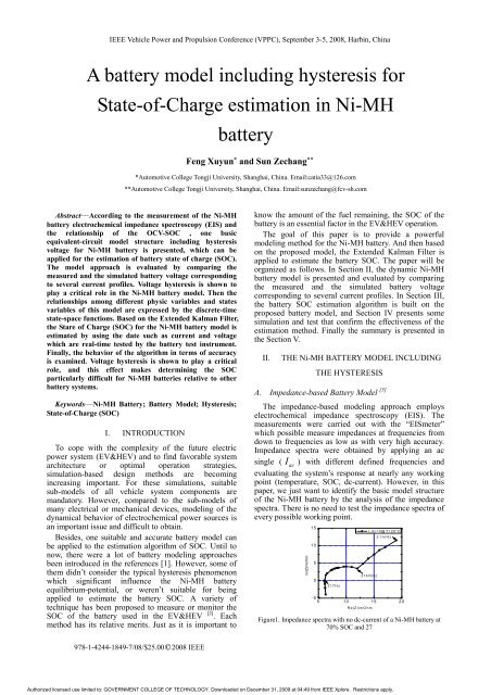
IEEE Vehicle Power and Propulsion Conference (VPPC), September 3-5, 2008, Harbin, ChinaA <strong>battery</strong> <strong>model</strong> <strong>including</strong> <strong>hysteresis</strong> <strong>for</strong><strong>State</strong>-<strong>of</strong>-<strong>Charge</strong> <strong>estimation</strong> in Ni-MH<strong>battery</strong>Feng Xuyun * and Sun Zechang ***Automotive College Tongji University, Shanghai, China. Email:catia33@126.com**Automotive College Tongji University, Shanghai, China. Email:sunzechang@fcv-sh.comAbstract—According to the measurement <strong>of</strong> the Ni-MH<strong>battery</strong> electrochemical impedance spectroscopy (EIS) andthe relationship <strong>of</strong> the OCV-SOC , one basicequivalent-circuit <strong>model</strong> structure <strong>including</strong> <strong>hysteresis</strong>voltage <strong>for</strong> Ni-MH <strong>battery</strong> is presented, which can beapplied <strong>for</strong> the <strong>estimation</strong> <strong>of</strong> <strong>battery</strong> state <strong>of</strong> charge (SOC).The <strong>model</strong> approach is evaluated by comparing themeasured and the simulated <strong>battery</strong> voltage correspondingto several current pr<strong>of</strong>iles. Voltage <strong>hysteresis</strong> is shown toplay a critical role in the Ni-MH <strong>battery</strong> <strong>model</strong>. Then therelationships among different physic variables and statesvariables <strong>of</strong> this <strong>model</strong> are expressed by the discrete-timestate-space functions. Based on the Extended Kalman Filter,the Stare <strong>of</strong> <strong>Charge</strong> (SOC) <strong>for</strong> the Ni-MH <strong>battery</strong> <strong>model</strong> isestimated by using the date such as current and voltagewhich are real-time tested by the <strong>battery</strong> test instrument.Finally, the behavior <strong>of</strong> the algorithm in terms <strong>of</strong> accuracyis examined. Voltage <strong>hysteresis</strong> is shown to play a criticalrole, and this effect makes determining the SOCparticularly difficult <strong>for</strong> Ni-MH batteries relative to other<strong>battery</strong> systems.Keywords—Ni-MH Battery; Battery Model; Hysteresis;<strong>State</strong>-<strong>of</strong>-<strong>Charge</strong> (SOC)I. INTRODUCTIONTo cope with the complexity <strong>of</strong> the future electricpower system (EV&HEV) and to find favorable systemarchitecture or optimal operation strategies,simulation-based design methods are becomingincreasing important. For these simulations, suitablesub-<strong>model</strong>s <strong>of</strong> all vehicle system components aremandatory. However, compared to the sub-<strong>model</strong>s <strong>of</strong>many electrical or mechanical devices, <strong>model</strong>ing <strong>of</strong> thedynamical behavior <strong>of</strong> electrochemical power sources isan important issue and difficult to obtain.Besides, one suitable and accurate <strong>battery</strong> <strong>model</strong> canbe applied to the <strong>estimation</strong> algorithm <strong>of</strong> SOC. Until tonow, there were a lot <strong>of</strong> <strong>battery</strong> <strong>model</strong>ing approachesbeen introduced in the references [1]. However, some <strong>of</strong>them didn’t consider the typical <strong>hysteresis</strong> phenomenonwhich significant influence the Ni-MH <strong>battery</strong>equilibrium-potential, or weren’t suitable <strong>for</strong> beingapplied to estimate the <strong>battery</strong> SOC. A variety <strong>of</strong>technique has been proposed to measure or monitor theSOC <strong>of</strong> the <strong>battery</strong> used in the EV&HEV [2] . Eachmethod has its relative merits. Just as it is important toknow the amount <strong>of</strong> the fuel remaining, the SOC <strong>of</strong> the<strong>battery</strong> is an essential factor in the EV&HEV operation.The goal <strong>of</strong> this paper is to provide a powerful<strong>model</strong>ing method <strong>for</strong> the Ni-MH <strong>battery</strong>. And then basedon the proposed <strong>model</strong>, the Extended Kalman Filter isapplied to estimate the <strong>battery</strong> SOC. The paper will beorganized as follows. In Section II, the dynamic Ni-MH<strong>battery</strong> <strong>model</strong> is presented and evaluated by comparingthe measured and the simulated <strong>battery</strong> voltagecorresponding to several current pr<strong>of</strong>iles. In Section III,the <strong>battery</strong> SOC <strong>estimation</strong> algorithm is built on theproposed <strong>battery</strong> <strong>model</strong>, and Section IV presents somesimulation and test that confirm the effectiveness <strong>of</strong> the<strong>estimation</strong> method. Finally the summary is presented inthe Section V.II.THE Ni-MH BATTERY MODEL INCLUDINGTHE HYSTERESISA. Impedance-based Battery Model [3]The impedance-based <strong>model</strong>ing approach employselectrochemical impedance spectroscopy (EIS). Themeasurements were carried out with the “EISmeter”which possible measure impedances at frequencies fromdown to frequencies as low as with very high accuracy.Impedance spectra were obtained by applying an acsingle ( Iac) with different defined frequencies andevaluating the system’s response at nearly any workingpoint (temperature, SOC, dc-current). However, in thispaper, we just want to identify the basic <strong>model</strong> structure<strong>of</strong> the Ni-MH <strong>battery</strong> by the analysis <strong>of</strong> the impedancespectra. There is no need to test the impedance spectra <strong>of</strong>every possible working point.Im(Z)/mOhm151050217Hz214mHz2.1mHz-55 10 15 20Re(Z)/mOhmI_dc=0@T=20 o CFigure1. Impedance spectra with no dc-current <strong>of</strong> a Ni-MH <strong>battery</strong> at70% SOC and 27978-1-4244-1849-7/08/$25.00○C 2008 IEEEAuthorized licensed use limited to: GOVERNMENT COLLEGE OF TECHNOLOGY. Downloaded on December 31, 2009 at 04:49 from IEEE Xplore. Restrictions apply.
IEEE Vehicle Power and Propulsion Conference (VPPC), September 3-5, 2008, Harbin, ChinaThe impedance spectra (Figure1) were obtained byapplying the “EISmeter” with no dc-current <strong>of</strong> theNi-MH <strong>battery</strong> at 70%SOC and temperature. Theequivalent elements included in the <strong>battery</strong> <strong>model</strong> can beidentified by evaluation <strong>of</strong> the impedance spectra [3] : Thespectra show an inductive behavior ( L ) at the highfrequencies; The intersection point with the real axis candetermine the <strong>battery</strong> pure ohmic resistance R ; Thesemicircle from the high frequencies to the lowerfrequencies can be <strong>model</strong>ed by a parallel connection <strong>of</strong> anon-linear resistor R ctand a capacitor Cdl; At thelower frequencies, the <strong>battery</strong> diffusion behavior <strong>of</strong> the<strong>battery</strong> becomes apparent which is commonly <strong>model</strong>edby a so-called Warburg impedance Zw. Hence, based onthe analysis <strong>of</strong> the impedance spectra, the basic Ni-MH<strong>battery</strong> <strong>model</strong> structure can be developed as the figure2.However, according to the equivalent trans<strong>for</strong>m relations,different circuits may processes completely identicalimpedance spectroscopy. The basic <strong>model</strong> structurepresented in this paper is the combination <strong>of</strong> theconsideration <strong>of</strong> the simplicity and sufficient knowledgeinvolved in the impedance spectra.OCV( V)7.17.06.96.86.76.66.56.46.36.26.1Di s c har geChar ge6.00 10 20 30 40 50 60 70 80 90 100SOC( %)Figure 3. Measured Ni-MH <strong>battery</strong> Open-circuit voltage values underdifferent SOC, the lower curve measured after discharging steps (-1C)with rest periods (3600s) in between, and the upper curve measuredafter charging steps (+1C).Besides the test <strong>of</strong> completed charge/dischargeSOC-OCV relationship, we also gained the relationship<strong>of</strong> OCV-SOC under partial charge/discharge as the figure4.LRC d lZ w7.17.06.9Di s c har geChar geFigure2. The basic equivalent electrical circuit structure <strong>of</strong> the Ni-MH<strong>battery</strong> in frequency domain determined by the impedance spectrawithout <strong>model</strong>ing the equilibrium potential.R c tOCV( V)6.86.76.6B. Hysteresis Phenomenon in Ni-MH BatteryFor most electrochemical system the equilibriumpotential is unambiguously defined by the state <strong>of</strong> charge(SOC). However, the Ni-MH <strong>battery</strong> shows a significant<strong>hysteresis</strong> <strong>of</strong> the open circuit potential [4] , with thepotential on charge being higher than on discharge atevery SOC (Figure2). The more detailed explanation <strong>of</strong>the voltage <strong>hysteresis</strong> characteristics could refer to thepaper [4], [5].The figure 3 is the depiction <strong>of</strong> theSOC-OCV relationship <strong>of</strong> one certain Ni-MH batterieswhich is composed <strong>of</strong> five single cells in series. In thefigure 3, we can obviously recognize the stabledifference <strong>of</strong> the open-circuit potential undercharge/discharge condition. That means that the potentialdoes not depend solely on the state <strong>of</strong> charge but also onthe history <strong>of</strong> charging and discharging <strong>of</strong> the electrode.6.56.410 20 30 40 50 60 70 80 90 100SOC( %)Figure 4. Measured Ni-MH <strong>battery</strong> OCV-SOC under partialcharge/dischargeIII. SCHEMATIC PRESENTATION OF THEEQUIVALENT CIRCUIT MODELFinally, based on the impedance-based <strong>model</strong> structureand Ni-MH <strong>battery</strong> <strong>hysteresis</strong> phenomenon testbehaviors, one equivalent circuit <strong>model</strong> <strong>including</strong> the<strong>hysteresis</strong> voltage <strong>model</strong> is presented as the figure. In thefigure, one <strong>hysteresis</strong> voltage <strong>model</strong> Vhwas included inthe part <strong>of</strong> V oc.The inductive element L hasn’t beenincluded in the <strong>model</strong> since the Ni-MH batteries are lessused at so high frequencies. Besides, we used one linearresistor paralleled with the capacitor in the <strong>model</strong> and weneed the further investigation on the non-linear resistorin the future work. Any other else electric elements inthe <strong>model</strong> are the same as the explanations <strong>of</strong>pre-provided impedance-based <strong>model</strong>.Authorized licensed use limited to: GOVERNMENT COLLEGE OF TECHNOLOGY. Downloaded on December 31, 2009 at 04:49 from IEEE Xplore. Restrictions apply.
IEEE Vehicle Power and Propulsion Conference (VPPC), September 3-5, 2008, Harbin, ChinaIU 0=V ocC 0RV h Z wFigure 5. Equivalent circuit <strong>model</strong> <strong>for</strong> the Ni-MH <strong>battery</strong>.According to some <strong>for</strong>mer works on the Ni-MH<strong>battery</strong> <strong>hysteresis</strong> phenomenon and the reference [6], the<strong>hysteresis</strong> voltage <strong>model</strong> can be described as thefollowing equation:<strong>Charge</strong>:t−RC h0 h,maxU = U * + U ∗(1 − RC h ) (1)hDischarge:et−RC h0 h,maxU = U * −U∗(1 − RC h ) (2)heAnd the implementation <strong>of</strong> the Warburg impedanceZ in the Matlab/Simulink will refer to the paper [7].wIV.V tTHE Ni-MH BATTERY SOC ESTIMATIONUSING EKF BASED ON THE PRESENTED MODELIn order to use Kalman-based methods <strong>for</strong> the Ni-MH<strong>battery</strong> SOC <strong>estimation</strong>, we must first have a cell <strong>model</strong>in a discrete-time state-space <strong>for</strong>m. Specifically, weassume the <strong>for</strong>m:x = + 1f( x , u ) + w(3)k k k ky = gx ( , u)+ v(4)k k k kEq.(3) is called the “state equation” or “processequation”, and Eq.(4) is the “output equation”. Then, weconvert the proposed <strong>battery</strong> <strong>model</strong> to the state equation.The <strong>battery</strong> SOC is constrained to be a member <strong>of</strong> thestate vector xk; the vector ukcontains theinstantaneous cell current ik.the cell loaded terminalvoltage is considered to the output yk. Finally, theoverall state-space equations <strong>for</strong> the Ni-MH <strong>battery</strong><strong>model</strong> are:⎡ 0 sign ( ik) F( ik)⎤⎡Uhk ( + 1) ⎤ ⎡1 −Fi(k) 0⎤⎡Uhk ( ) ⎤ ⎢ ikη t⎥⎡ ⎤⎢ ⎥= ⎢Z 0 1⎥⎢ ⎥+ Δ0⎢U⎥(5)k+1Z ⎢ ⎥⎣ ⎦ ⎣ ⎦⎣ k ⎦ h,max⎢ C⎣ ⎦⎣ n ⎥ ⎦U = U ( z ) + i R+ U + U(6)eek ocv k k ct ( k ) h( k )The <strong>battery</strong> SOC and <strong>hysteresis</strong> voltage are denotedZU hkask( )( )and respectively. Where andZkare the two members <strong>of</strong> the state vectorxk . In theUEq.(), Eq.(),k is the <strong>battery</strong> loaded terminal voltage,−C dl−R ctttU hkikis the discharge/charge current, R is the cell internalUocvand Uctare the open-circuit voltageR C in parallel,resistance,and the voltage <strong>of</strong> the ct dlUh,maxisthe max value <strong>of</strong> the <strong>hysteresis</strong> voltage.Finally the EKF basic principle can be applied toestimate the state <strong>of</strong> the equation. The main EKFalgorithm equations are summarized in the TableI:TABLE I.SUMMARY OF THE NON-LINEAR EXTENDKALMAN FILTER (EKF) [9]Non-linear state-pace <strong>model</strong>xk + 1= f ( xk , uk) + wkyk= g( xk, uk)+ vkDefinitionsˆ ∂ f ( xk, uk) ,Ak − 1=ˆ ∂ g ( xk, uk)Ck=∂ xk+ ∂ xx k = xˆk −k−1x k = xˆkInitializationˆ + + + Tx0 = E ( x0), P ˆ ˆ0= E[( x0 − x0 )( x0 − x0) ]ComputationFor k=1,2,3,…compute− +<strong>State</strong> <strong>estimation</strong> time update: xˆ( ˆk= f xk−1, uk−1)−Error covariance time update: P Tk= Ak− 1Pk−1Ak−1+Qk−1− T − T −1Kalman gain matrix: Kk = P C ( )k kCkP Ck k+ Rk<strong>State</strong> <strong>estimation</strong> measurement update:+ − −xˆ ˆ [ ( ˆk= xk + Kkyk − g xk , uk)]Error covariance measurement update:+ −Pk = ( E − KkCk)PkThen, we should summarize some <strong>model</strong> function, andaccording to the basic principle <strong>of</strong> the EKF, someunknown parameters and function in the EKF algorithmcould also be derived from the presented <strong>model</strong> equation(5),(6), which are summarized in the Table IITABLE II.SUMMARY OF THE PARAMETERS IN THE MODELAND EKF ALGORITHMF ( i ) = exp( −βi Δt)kk⎡sign( ik) F ( ik)Uh,max⎤⎡1 − F( ik) 0⎤ f ( x , u ) = x⎢η t⎥⎢ u0 1⎥ + Δ⎣⎦⎢ ⎥⎢⎣Cn ⎥⎦g ( x , u ) = U ( x [1]) + x [2] + U + RuAˆk − 1k k k kk k ocv k k ct( k )k∂ f ( x , )1 (k) 0ku− F ik⎡⎤= =∂ x⎢k0 1 ⎥⎣ ⎦+x k = xˆk − 1ˆ ∂ g ( x , u ) dUCk= = ( ,1)dSOCk k OCV∂ xk x −k = x ˆ kThe parameter β could be derived from the <strong>hysteresis</strong>Authorized licensed use limited to: GOVERNMENT COLLEGE OF TECHNOLOGY. Downloaded on December 31, 2009 at 04:49 from IEEE Xplore. Restrictions apply.
IEEE Vehicle Power and Propulsion Conference (VPPC), September 3-5, 2008, Harbin, ChinadUOCVvoltage test, andcould be calculateddSOCfrom the relationship curve <strong>of</strong> the OCV-SOC.V. EVALUATION OF THE MODEL ANDMETHOD OF SOC ESTIMATIONFirst, the presented Ni-MH <strong>battery</strong> <strong>model</strong> is evaluatedby comparing the measured and the simulated <strong>battery</strong>voltage corresponding to several current pr<strong>of</strong>iles. As thefigure 6, the <strong>battery</strong> was charged and discharged underpulse current (1C, about 60S). We used two different<strong>model</strong>s that one includes the <strong>hysteresis</strong> <strong>model</strong> and theother without. The comparison result indicated that the<strong>hysteresis</strong> <strong>model</strong> plays one great role in the Ni-MH<strong>battery</strong> <strong>model</strong>.Voltage(V)1.501.481.461.441.421.401.381.361.341.321.301.28Measured VoltageSimulated Voltage(no Hysteresis Model)Simulated Voltage1.260 200 400 600 800 1000 1200 1400Time(s)Figure6. Comparison <strong>of</strong> the measured voltage with the <strong>model</strong> simulatedvoltage, one simulation <strong>model</strong> <strong>including</strong> the <strong>hysteresis</strong> <strong>model</strong> and theother one without the <strong>hysteresis</strong> <strong>model</strong>In the figure 7, the measured <strong>battery</strong> voltage wascompared with the <strong>model</strong> simulation voltage under onerandom current load.Vol t age( V)46444240383634Mode l Si mul at i on Vol t ageMeasur ed Vol t age0 500 1000 1500 2000 2500 3000 3500 4000Ti me( S)1.3701.3651.3601.355600 640 680Figure7. Comparison <strong>of</strong> measured and simulated voltage correspondingto one random current pr<strong>of</strong>ileSecond, the behavior <strong>of</strong> the <strong>battery</strong> SOC algorithmwhich is based on the presented Ni-MH <strong>battery</strong> <strong>model</strong> isalso evaluated under one random discharge/chargecurrent test. The Figure 8 is the current pr<strong>of</strong>ile <strong>of</strong> the testand figure9 is the SOC <strong>estimation</strong> result <strong>of</strong> using themethod EKF and Ah-integration respectively.Cur r ent ( A)40200-20-40-60-801000 2000 3000 4000 5000 6000 7000 8000 9000Ti me( S)Figure8. Input random current pr<strong>of</strong>iles to evaluate the SOC <strong>estimation</strong>algorithmSOC( %)6050403020100-10-20-301000 2000 3000 4000 5000 6000 7000 8000 9000Ti me( S)EKFAh- i nt egr at i onFigure9. Comparison <strong>of</strong> the SOC <strong>estimation</strong> using EKF andAh-integration respectively under the current loads as the figure 8In the Figure 9, the SOC Estimation results werecompared with the Ah-integration method which canreach one certain accuracy in one short time. We couldrecognize that there is the obvious deviation between thetwo <strong>estimation</strong> results. We could see that the <strong>estimation</strong>result <strong>of</strong> the Ah-integration method reach to one negativevalue when the <strong>battery</strong> was nearly to be fully discharged.Apparently, the EKF <strong>estimation</strong> method avoided thedeficit that the <strong>estimation</strong> errors have been integratedgradually during the test in the Ah-integration method,and one more accurate <strong>estimation</strong> result could be gained.VI. CONCLUTIONIn this paper one equivalent circuit <strong>model</strong> <strong>including</strong>the <strong>hysteresis</strong> voltage <strong>model</strong> <strong>for</strong> Ni-MH <strong>battery</strong> has beenpresented. We used the method <strong>of</strong> EIS to identify theNi-MH <strong>battery</strong> <strong>model</strong> structure. Then combined withsome current-voltage response tests, the basic Ni-MHCDABAuthorized licensed use limited to: GOVERNMENT COLLEGE OF TECHNOLOGY. Downloaded on December 31, 2009 at 04:49 from IEEE Xplore. Restrictions apply.
IEEE Vehicle Power and Propulsion Conference (VPPC), September 3-5, 2008, Harbin, China<strong>battery</strong> <strong>model</strong> <strong>including</strong> the <strong>hysteresis</strong> was established.And then an EKF based algorithm has been developed toestimate SOC. The proposed method can accurately<strong>model</strong> the dynamic behavior <strong>of</strong> the <strong>battery</strong> which makesit appropriate <strong>for</strong> HEV application. Finally, the capabilityand accuracy <strong>of</strong> the proposed method in <strong>estimation</strong> SOC<strong>of</strong> the Ni-MH batteries is verified by the evaluationworks.VII. ACKNOWLEDGMENTThis work was greatly supported by the ShanghaiScience and Technology Commission <strong>of</strong> Shanghai andShanghai Fuel Cell Vehicle Powertrain Co., Ltd. The<strong>battery</strong> test laboratory in Automobile College, TongjiUniversity, provided the test facilities used in the wholeperiod <strong>of</strong> investigation. Many enlightening discussionswith Pro. Sun Zechang, Associate Pro. Wei Xuezhe andPh.D Dai Haifeng are gratefully acknowledged. Besidesmany colleagues such as Yuan Yongjun, Wang Jiayuanare also acknowledged.REFERENCES[1] Chen Quanshi, Lin Chengtao. “Summarization <strong>of</strong> studies onper<strong>for</strong>mance <strong>model</strong>s <strong>of</strong> batteries <strong>for</strong> electric vehicle”. AutomobileTechnology, 2005, 37(3):1-5.[2] S.Piller, M.Perrin, A.Jossen. “Methods <strong>for</strong> state-<strong>of</strong>-chargedetermination and their application”. Journal <strong>of</strong> Power Sources,96: (2001)113-120.[3] Marc Thele, Oliver Bohlen, Dirk Uwe Sauer. “Development <strong>of</strong> avoltage-behavior <strong>model</strong> <strong>for</strong> NiMH batteries using animpedance-based <strong>model</strong>ing concept”. J. Power Sources, 2008,175 (2008) 635-643.[4] Venkat Srinivasan, John W.Weidner, and John Newman.“Hysteresis during Cycling <strong>of</strong> Nickel Hydride Active Material”. J.Electrochemical Society, 2001, 148(9):696-980.[5] M.W. Verbrugge, Edwad Tate. “Adaptive state <strong>of</strong> chargealgorithm <strong>for</strong> nickel metal hydride <strong>battery</strong> <strong>including</strong> <strong>hysteresis</strong>phenomena”. J <strong>of</strong> Power Sources,2004,126: 236-249.[6] Feng Xuyun, Wei Xuezhe. “Study on the Ni-MH BatteryEquivalent Circuit <strong>model</strong>. Battery”, 2007, Vol.37(4):286-288.[7] S.Buller. “Impedence-based simulation <strong>model</strong>s <strong>for</strong> energy storagedevices in advanced automotive power system”. PhD Thesis,RWTH Aachen Univercity, 2002, ISBN: 3-8322-1225-6.[8] Wu Hongjie, Qi Bojin, Zheng Minxin, Liu Yongzhe. “Ni-MH<strong>battery</strong> state-<strong>of</strong>-charge <strong>estimation</strong> based on Kalman filter”. J.Beijing University <strong>of</strong> Aeronautics and Astronautics, 2007,33(8):945-948.[9] Deng zili. Kalman filter and Vina filter [M]. Harbin: HarbinIndustry University Publisher, 2001.Authorized licensed use limited to: GOVERNMENT COLLEGE OF TECHNOLOGY. Downloaded on December 31, 2009 at 04:49 from IEEE Xplore. Restrictions apply.