A battery model including hysteresis for State-of-Charge estimation ...
A battery model including hysteresis for State-of-Charge estimation ...
A battery model including hysteresis for State-of-Charge estimation ...

You also want an ePaper? Increase the reach of your titles
YUMPU automatically turns print PDFs into web optimized ePapers that Google loves.
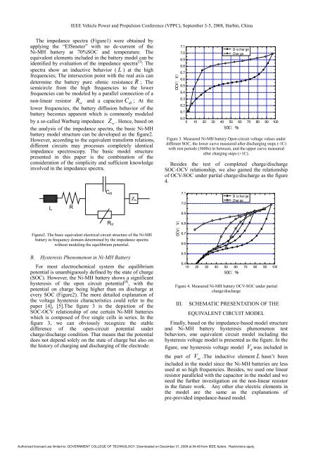
IEEE Vehicle Power and Propulsion Conference (VPPC), September 3-5, 2008, Harbin, ChinaThe impedance spectra (Figure1) were obtained byapplying the “EISmeter” with no dc-current <strong>of</strong> theNi-MH <strong>battery</strong> at 70%SOC and temperature. Theequivalent elements included in the <strong>battery</strong> <strong>model</strong> can beidentified by evaluation <strong>of</strong> the impedance spectra [3] : Thespectra show an inductive behavior ( L ) at the highfrequencies; The intersection point with the real axis candetermine the <strong>battery</strong> pure ohmic resistance R ; Thesemicircle from the high frequencies to the lowerfrequencies can be <strong>model</strong>ed by a parallel connection <strong>of</strong> anon-linear resistor R ctand a capacitor Cdl; At thelower frequencies, the <strong>battery</strong> diffusion behavior <strong>of</strong> the<strong>battery</strong> becomes apparent which is commonly <strong>model</strong>edby a so-called Warburg impedance Zw. Hence, based onthe analysis <strong>of</strong> the impedance spectra, the basic Ni-MH<strong>battery</strong> <strong>model</strong> structure can be developed as the figure2.However, according to the equivalent trans<strong>for</strong>m relations,different circuits may processes completely identicalimpedance spectroscopy. The basic <strong>model</strong> structurepresented in this paper is the combination <strong>of</strong> theconsideration <strong>of</strong> the simplicity and sufficient knowledgeinvolved in the impedance spectra.OCV( V)7.17.06.96.86.76.66.56.46.36.26.1Di s c har geChar ge6.00 10 20 30 40 50 60 70 80 90 100SOC( %)Figure 3. Measured Ni-MH <strong>battery</strong> Open-circuit voltage values underdifferent SOC, the lower curve measured after discharging steps (-1C)with rest periods (3600s) in between, and the upper curve measuredafter charging steps (+1C).Besides the test <strong>of</strong> completed charge/dischargeSOC-OCV relationship, we also gained the relationship<strong>of</strong> OCV-SOC under partial charge/discharge as the figure4.LRC d lZ w7.17.06.9Di s c har geChar geFigure2. The basic equivalent electrical circuit structure <strong>of</strong> the Ni-MH<strong>battery</strong> in frequency domain determined by the impedance spectrawithout <strong>model</strong>ing the equilibrium potential.R c tOCV( V)6.86.76.6B. Hysteresis Phenomenon in Ni-MH BatteryFor most electrochemical system the equilibriumpotential is unambiguously defined by the state <strong>of</strong> charge(SOC). However, the Ni-MH <strong>battery</strong> shows a significant<strong>hysteresis</strong> <strong>of</strong> the open circuit potential [4] , with thepotential on charge being higher than on discharge atevery SOC (Figure2). The more detailed explanation <strong>of</strong>the voltage <strong>hysteresis</strong> characteristics could refer to thepaper [4], [5].The figure 3 is the depiction <strong>of</strong> theSOC-OCV relationship <strong>of</strong> one certain Ni-MH batterieswhich is composed <strong>of</strong> five single cells in series. In thefigure 3, we can obviously recognize the stabledifference <strong>of</strong> the open-circuit potential undercharge/discharge condition. That means that the potentialdoes not depend solely on the state <strong>of</strong> charge but also onthe history <strong>of</strong> charging and discharging <strong>of</strong> the electrode.6.56.410 20 30 40 50 60 70 80 90 100SOC( %)Figure 4. Measured Ni-MH <strong>battery</strong> OCV-SOC under partialcharge/dischargeIII. SCHEMATIC PRESENTATION OF THEEQUIVALENT CIRCUIT MODELFinally, based on the impedance-based <strong>model</strong> structureand Ni-MH <strong>battery</strong> <strong>hysteresis</strong> phenomenon testbehaviors, one equivalent circuit <strong>model</strong> <strong>including</strong> the<strong>hysteresis</strong> voltage <strong>model</strong> is presented as the figure. In thefigure, one <strong>hysteresis</strong> voltage <strong>model</strong> Vhwas included inthe part <strong>of</strong> V oc.The inductive element L hasn’t beenincluded in the <strong>model</strong> since the Ni-MH batteries are lessused at so high frequencies. Besides, we used one linearresistor paralleled with the capacitor in the <strong>model</strong> and weneed the further investigation on the non-linear resistorin the future work. Any other else electric elements inthe <strong>model</strong> are the same as the explanations <strong>of</strong>pre-provided impedance-based <strong>model</strong>.Authorized licensed use limited to: GOVERNMENT COLLEGE OF TECHNOLOGY. Downloaded on December 31, 2009 at 04:49 from IEEE Xplore. Restrictions apply.