
Create successful ePaper yourself
Turn your PDF publications into a flip-book with our unique Google optimized e-Paper software.
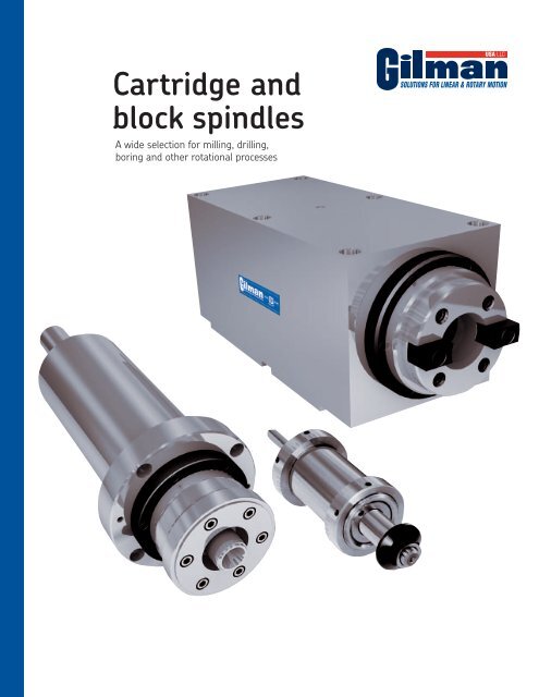
<strong>Cartridge</strong> <strong>and</strong><strong>block</strong> <strong>spindles</strong>A wide selection for milling, drilling,boring <strong>and</strong> other rotational processes
SizinginstructionsProper spindle sizing is important to ensure a long <strong>and</strong> dependablelife. To help select the correct spindle, the followingfactors should be considered.General rules for sizing1 Always select the largest spindle that will fit your particularspace <strong>and</strong> comply with the speed requirements.This will give you the maximum spindle stiffness <strong>and</strong>longest life.2 Keep tool overhang to a minimum, particularly whenboring, end milling or nonsupported arbor milling. Asyou move farther from the spindle bearings, bearingloads increase <strong>and</strong> spindle stiffness decreases. Usethe specification charts to find the maximum overhangdistance.3 When boring, the spindle nose bearing I.D. should beas large or larger than the hole being machined.4 To minimize any shaft or bearing loading, keep withinthe maximum torque rating given on the specificationcharts.5 Consider the environment in which the spindle is used.If the conditions are dusty, air purging is recommended.If there is heavy coolant or chips, it is advisable tosupply a deflector cover to keep coolant or chips fromdirectly attacking the spindle. Contact seals should beused unless speed requirements do not allow.6 Specify the correct bearing arrangement. For mostly radialloaded applications, use a bearing pair at the nose end. Forhigh axial loads, combination axial <strong>and</strong> radial loading orheavy or interrupted cuts, use a triplex bearing set at thenose end.7 <strong>Gilman</strong> <strong>USA</strong>’s engineering <strong>and</strong> sales staff is always availableto help select the correct <strong>spindles</strong> for your applications. Whenasking for assistance, please supply the following information:a) Type of operation <strong>and</strong> stock removal amountsb) Tooling descriptionc) Part material specificationd) Spindle orientatione) Environmental conditionsf) Space limitationsg) Horsepower <strong>and</strong> RPM requiredWhenever possible, supply a part print along with any other informationthat may be useful in spindle selection.©2011 <strong>Gilman</strong> <strong>USA</strong>, LLC5
OrderinginstructionsEach spindle assembly is defined by the model number, which consistsof a maximum of seven code symbols.<strong>Cartridge</strong> <strong>and</strong> <strong>block</strong> <strong>spindles</strong> are identified by the first five codesymbols. The first symbol determines the size of the spindle. Thesecond symbol identifies the cartridge mounting or <strong>block</strong> configuration.The third symbol identifies the internal construction type<strong>and</strong> the fourth identifies the nose end bearing preload. The fifthsymbol identifies the type of spindle nose.Specify speed when ordering. Brackets are available for all cartridge<strong>spindles</strong>, see dimension sheets for model numbers.Motorized Spindles use the first five code symbols of the cartridgeassembly, <strong>and</strong> the sixth code symbol to describe the type ofmotor drive.On most belt drive units, the motor can bepositioned at four locations around the spindle A(see drawing at right), but motor positionsare not field changeable. Position “A” will befurnished unless otherwise specified. Motordimensions <strong>and</strong> frame size may vary.DBIf exact dimensions are required, requestcertified print.Specify spindle speed when ordering. Allmotors will be supplied 230/460 volt, 3CMotor positionsphase 60 cycle. Consult factory for othermotorspecifications <strong>and</strong> spindle speeds not shown in charts.Motorized vertical travel <strong>spindles</strong> use all seven code symbols.The last symbol identifies the slide drive. All vertical travel beltdrive units use the B1 belt drive in Position “A”.You can readily determine the spindle model number as you decideon size, cartridge mounting, internal construction, shaft type<strong>and</strong> if motorized or vertical travel drives are required.Check to see that each code symbol in the model number isindicated under the size selected <strong>and</strong> to the left in the columnunder the assembly selected. These are the spindle assembliesthat are available.We can give prompt accurate service if complete information isprovided with the order. If you have any questions, please phoneour Sales Engineering Department at (262) 377-2434.Specify air purge if required. Fittings will be supplied uponrequest on nose end of cartridge <strong>spindles</strong> <strong>and</strong> each end of <strong>block</strong><strong>spindles</strong>.Model number codeMotorized vertical travel spindleMotorized spindleBlock spindle<strong>Cartridge</strong> spindleSize12501875275035004000550065008000DescriptionCodeTypePlain housing cartridgePPositioning nut cartridgeNFlange housing cartridgeCBlock housingBInternal constructionDuplex ball nose end, contact sealX1Duplex ball nose end, labyrinth sealX2Duplex ceramic ball nose end, lab sealX2CTriplex ball nose end, contact sealX3Triplex ball nose end, labyrinth sealX4Triplex ceramic ball nose end, lab sealX4CNose end bearing preloadLight preloadLMedium preload M‡Heavy preloadHShaft noseArborAR°Morse taperMTStraight boreSTBoring noseBNColletCEHSK manual adapterHM30 NMTB 3040 NMTB 4050 NMTB 50Motor driveBelt – motor drive end (high HP) B1+Belt – motor nose end (high HP)B2Belt – motor drive end (low HP)B3Belt – motor nose end (low HP)B4Slide driveBall lead screw powered drive D1,M1,D2,M2,D3,M3Lead screw right angle manual driveE1Hydraulic cylinder stop rodH2° 1250 Arbor nose not available in motorized. + B1 available in 6500 vertical travel motorized spindle.‡ Medium preload is offered as st<strong>and</strong>ard. Light <strong>and</strong> heavy preload are available upon request. 1250 <strong>and</strong> 1875 only available with medium preload.2750C-X1M-30-B1-E1The engineering department of <strong>Gilman</strong> <strong>USA</strong>reserves the right to change specificationswithout notice. Do not base final decisionson catalog drawings — ask for a certifiedprint when you order a spindle.If servicing should be required on any<strong>Gilman</strong> spindle, we suggest the unitbe returned for factory service to assureoptimum performance <strong>and</strong> life.6 ©2011 <strong>Gilman</strong> <strong>USA</strong>, LLC
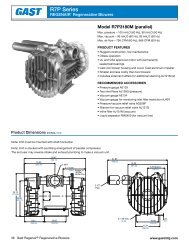
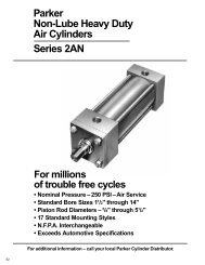
<strong>Gilman</strong>1875NMotorized <strong>spindles</strong>1875N B1 & B2Spindle R.P.M.MotorMinimum Maximum R.P.M. H.P. Frame800 2350 1160 1/3 48C1150 3500 1750 1/4 or 1/2 48C2300 10500 3500 1/3 or 1/2 48C1875N motorized <strong>spindles</strong>are fixed-speed units incorporatinga timing belt drivefor positive power transmission.Poly-V,V-belt <strong>and</strong> flat-belt drivesare available at additionalcost where high speed <strong>and</strong>minimum vibration arerequired. For 1875N spindlecapabilities reference the1875 specification chart.*8.502.00.385.002.50B1B2Ø5.624.6211.576.62 Max.5.50 Min.4.00.142.0001.622.12.3753.124.255/16 Soc. HD. C.S. (4)*.381.75.56.561.6254.001.6252.000Approx. wt. 35 lbs.Note: * See 1875N <strong>spindles</strong> on page 8.©2011 <strong>Gilman</strong> <strong>USA</strong>, LLC9
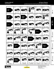
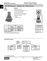
<strong>Gilman</strong>2750C<strong>Cartridge</strong> <strong>spindles</strong>2750C cartridge <strong>spindles</strong> <strong>and</strong>2750B <strong>block</strong> <strong>spindles</strong> areavailable with five st<strong>and</strong>ardnose types <strong>and</strong> six st<strong>and</strong>ardinternal construction types.Nose types:• #30 N.M.T.B. taper• Boring nose• HSKC40 manual clamp• 1/16 to 3/4 ER32 collet• .750 diameter straight boreInternal constructions:• X1 duplex ball bearing atnose end with contact seal• X2 duplex ball bearing atnose end with labyrinth seal• X2C duplex ceramic ballbearing at nose end withlabyrinth seal• X3 triplex ball bearing atnose end with contact seal• X4 triplex ball bearing atnose end with labyrinth seal• X4C triplex ceramic ballbearing at nose end withlabyrinth sealRefer to the 2750C/2750Bspecification chart, as well asthe sizing instructions on page5, to select the proper spindlefor your rotational requirements.Special designs are alsoavailable to meet your specificneeds.2750C Approx. wt. 15 lbs.For cartridge spindlebrackets, see “<strong>Gilman</strong> spindleaccessories”, page 47.Ø2.7501/4 Sq. keyØ2.7501/4 Sq. keyØ2.7501/4 Sq. key1.25Ø.9371/4 Sq. key3.871.25 2.003.871.25 2.00Ø.9373.871.25 2.00Ø.93711.883.87 6.38 2.002.002.88Ø.5312.256.3812.846.38Ø.53Ø.691.03.631.03.63**2.5912.50 .536.382.251.62Ø.53Stop screw1.03.63**.311.03.62Ø2.750 Ø4.00Ø2.48Ø2.750 Ø4.00Ø.937Ø2.751.25Ø2.750Ø.9371/4 Sq. key30 - #30 N.M.T.B. Taper shaft3.882.00Ø.5312.006.38Ø.53BN - Boring nose1.03.621.753.122.00.38.72Ø2.75Ø2.25 Ø4.00Ø.750*2750C & 2750B Specification chartØ4.00Ø2.765/16 Soc. HD. C.S. (4)Ø3.38 B.C..6253/8-16 Tap (4)Ø2.125 B.C.Ø1.3803M5X0.8 Tap (6)Ø1.969 B.C.3/8-16 Soc. S.S.ER32 ColletCollet range 1/16 to 3/4(Collet <strong>and</strong> wrenchnot included)Ø2.25 Ø4.00Ø1.97Ø2.755/16 Soc. HD. C.S. (4)Ø3.38 B.C.HM - HSKC40 Manual clamp(T-wrench not included)Bearing Maximum Maximum Radial stiffness Nose end Drive end<strong>and</strong> seal thrust R.P.M. at noseconstruction (lbs.) (lbs./in.) Bearing Seal Bearing SealnumberCE - ER32 Collet shaftTool dia.1/16 to 9/16 4 in.Over 9/16 to 3/4 2 in.ST - Straight bore shaftX1L 46 5,300 180,000 30 mm I.D. 25mm I.D.X1M 139 5,300 200,000 duplex Contact duplex LabyrinthX1H 289 5,300 210,000 ball ballX2L 46 17,500 180,000 30 mm I.D. 25mm I.D.X2M 139 15,600 200,000 duplex Labyrinth duplex LabyrinthX2H 289 10,400 210,000 ball ballX2CL 34 27,200 180,000 30 mm I.D. 25mm I.D.X2CM 70 23,800 200,000 duplex Labyrinth duplex LabyrinthceramicceramicballballContinued on next pageMax tooldepth10 ©2011 <strong>Gilman</strong> <strong>USA</strong>, LLC
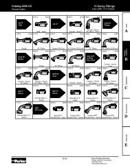
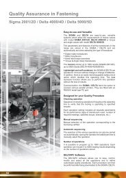
3.50.88 1.25 2.00.41Ø.9371/4 Sq. key11.887.00.311.382.88Ø.53 Ø.69.41Ø2.7505/16 Soc. HD. C.S. (4).6253.632.1251.75<strong>Gilman</strong>2750BBlock <strong>spindles</strong>(4) Tapped holes.See page 47for location.26.375.7505.8136.251.381.8133.81330 - #30 N.M.T.B. Taper shaft*3/8-16 Tap (4)Ø2.125 B.C.1.500 1.5003.75 1.875.62Locating edgeØ.9371.253.872.0012.257.00Ø.53.411.37.72Ø2.48Ø1.380 Ø2.75BN - Boring nose1/4 Sq. key*M5X0.8 Tap (6)Ø1.969 B.C.Ø.9373.871.25 2.0012.847.001.97Ø.53 .41Ø2.76HM - HSKC40 Manual clamp(T-wrench not included)1/4 Sq. key3.871.25 2.0012.50 .537.001.631.00Ø.53.41Ø2.25Ø.937 Ø1.97 Ø2.75*ER32 ColletCollet range 1/16 to 3/4(Collet <strong>and</strong> wrenchnot included)CE - ER32 Collet shaftMax toolTool dia. depth1/16 to 9/16 4 in.1/4 Sq. keyOver 9/16 to 3/42 in.*Stop screw3.881.25 2.00Ø.5312.007.003.12.411.13.38Ø.750ST - Straight bore shaftØ.937Ø2.75Ø2.251/4 Sq. key*3/8-16 Soc. S.S.2750C & 2750B Specification chart (continued)Bearing Maximum Maximum Radial stiffness Nose end Drive end<strong>and</strong> seal thrust R.P.M. at noseconstruction (lbs.) (lbs./in.) Bearing Seal Bearing SealnumberX3L 92 5,300 260,000 30 mm I.D. 25mm I.D.X3M 290 5,300 290,000 triplex Contact duplex LabyrinthX3H 655 5,300 300,000 ball ballX4L 92 15,600 260,000 30 mm I.D. 25mm I.D.X4M 290 10,400 290,000 triplex Labyrinth duplex LabyrinthX4H 655 8,300 300,000 ball ballX4CL 67 23,800 260,000 30 mm I.D. 25mm I.D.X4CM 138 18,700 290,000 triplex Labyrinth duplex Labyrinthceramicceramicballball2750B Approx. wt. 25 lbs.* Maximum tool overhang(from *) = 3 (in.)Maximum torque = 133 (in.- lbs.)WK 2 = 2.8 (lb.- in. 2 )Note: Spindles are supplied with medium bearingpreloads as st<strong>and</strong>ard. Light <strong>and</strong> heavy bearingpreloads are available.Tool overhang pertains to boring, end milling <strong>and</strong>nonsupported arbor milling.©2011 <strong>Gilman</strong> <strong>USA</strong>, LLC11
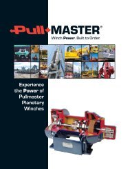
<strong>Gilman</strong>2750CMotorized <strong>spindles</strong>2750C B1 & B2Spindle R.P.M.MotorPosition Minimum Maximum R.P.M. H.P. FrameA & C 900 2350 1160 1 1/2 145TCB & D 900 1900A & C 1450 3500 1750 1 1/2 or 2 145TCB & D 1450 20502750C <strong>and</strong> 2750B motorized<strong>spindles</strong> are fixed-speed unitsincorporating a timing beltdrive for positive power transmission.Poly-V, V-belt <strong>and</strong>flat-belt drives are availableat additional cost where highspeed <strong>and</strong> minimum vibrationare required. The 2750C <strong>and</strong>2750B are available in twosizes: the B1/B2 units (highhorsepower) or B3/B4 units(low horsepower). For 2750spindle capabilities referencethe 2750 specification charts.*A & C 3300 7700 3500 2 or 3 145TCB & D 3300 625012.12B1.750.502.503.00.38.26B2*3.1885.1256.255/16 Soc. HD. C.S. (4)5.881.1251.88Ø7.194.251.750.816.753.384.255.8816.9010.38 Max.8.88 Min.2.1251.751.7502.1252750C B3 & B4Spindle R.P.M.MotorPosition Minimum Maximum R.P.M. H.P. FrameA & C 800 2350 1160 1/3 or 1/2 56CB & D 800 2350A & C 1200 3500 1750 1/2 or 3/4 56CB & D 1200 3500A & C 2400 7700 3500 3/4 or 1 56CB & D 2400 625010.253.00.381.886.753.38B3B4Ø7.194.0016.9010.38 Max.8.88 Min.4.252.125Approx. wt. 95 lbs..750.502.50.263.1885.1256.25*5/16 Soc. HD. C.S. (4)1.1251.750.814.255.881.751.7502.125Note: * See 2750C cartridge <strong>spindles</strong> on page 10.12 ©2011 <strong>Gilman</strong> <strong>USA</strong>, LLC
2750B B1 & B2Spindle R.P.M.MotorPosition Minimum Maximum R.P.M. H.P. FrameA & C 900 2350 1160 1 1/2 145TCB & D 900 1900A & C 1450 3500 1750 1 1/2 or 2 145TCB & D 1450 2050<strong>Gilman</strong>2750BMotorized <strong>spindles</strong>A & C 3300 7700 3500 2 or 3 145TCB & D 3300 625012.123.00.381.886.753.38B1B2Ø7.195.1216.9010.38 Max.8.88 Min.3.622.125.750.502.503.8135.8137.005/16 Soc.HD. C.S. (4).26*1.8131.5001.063.755.881.751.5001.8752750B B3 & B4Spindle R.P.M.MotorPosition Minimum Maximum R.P.M. H.P. FrameA & C 800 2350 1160 1/3 or 1/2 56CB & D 800 2350A & C 1200 3500 1750 1/2 or 3/4 56CB & D 1200 3500A & C 2400 7700 3500 3/4 or 1 56CB & D 2400 625010.253.00.381.886.753.38B3B4Ø7.193.2516.9010.38 Max.8.88 Min.3.622.125Approx. wt. 85 lbs..750.502.503.8135.8137.005/16 Soc. HD. C.S. (4).26*1.8131.5001.063.755.881.751.5001.875Note: * See 2750B <strong>block</strong> <strong>spindles</strong> on page 11.©2011 <strong>Gilman</strong> <strong>USA</strong>, LLC13
<strong>Gilman</strong>2750CMotorized verticaltravel <strong>spindles</strong>2750C motorized vertical travel spindle units are fixed-speed units that combinea motorized timing belt drive spindle with a vertical hardened steel way slide assembly.Vertical positioning of the saddle <strong>and</strong> spindle can be accomplished with oneof the eight st<strong>and</strong>ard drive types.The lead screw manual drive is a 2:1 reduction right angle drive <strong>and</strong> can bepositioned six ways with position #1 as st<strong>and</strong>ard (specify position number whenordering). For 2750C spindle capabilities, reference the 2750 specification charts.*H<strong>and</strong>wheel pos #1 STD.Pos. #2,3,4,5,& 6 optional3.50 3.001/4-20 Tap .50 DP. (4)2.375 B.C.3.003.501/8 Sq. key1.50#2#33/8 Soc. HD. C.S. (4)2.502.50 2.25Pos. #1#412.123.00.381.754.50Ø2.8756" Dia. h<strong>and</strong>wheel#6 #5.0005 graduated dial7.971.81 3.38 3.38Ø.5001.001.2513.88Ø7.192.754.503.389.50 Max.8.00 Min.*.38Typ.10.0016.623.3845“Y”3.91.624.88 1.3810.00.500Typ.8.004.00.20Typ.D1, M1 - Lead screw power drive.750-.200 Rolled ball screw R.H. Thd.D2, M2 - Lead screw power drive.750-.200 Ground ball screw R.H. Thd.D3, M3 - Lead screw power drive20mm-5mm Ground ball screw R.H. Thd.Note: * See 2750C cartridge <strong>spindles</strong> on page 10.**M1, M2, M3 - Motor mount for customersupplied motor. Consult factory for specifications.E1 - Lead screw power drive.750-.100 Acme screw L.H. Thd.Drive “Y” Min. “Y” Max.D1, M1 4.00 8.00D2, M2 4.00 7.00D3, M3 4.00 7.00E1 4.50 9.00H2 4.00 8.0014 ©2011 <strong>Gilman</strong> <strong>USA</strong>, LLC
Ø1.1873.50.88 2.001/4 Sq. key(4) Tapped holes.See page 47for location.2614.009.00 1.502.88.88.53Ø.53 Ø.69.375.7504.9387.6258.121.752.25030 - #30 N.M.T.B. Taper shaft*.31Ø3.00Ø3.75Ø2.7503/8-16 Tap (4)Ø2.125 B.C.5/16 Soc. HD. C.S. (4).6251.875 1.8752.2504.504.632.6252.25.62Locating edge<strong>Gilman</strong>3500BBlock <strong>spindles</strong>14.14.883.502.009.00Ø.53 .531.64.845/16 Soc. HD. C.S. (4)Ø1.1871/4 Sq. keyØ3.16Ø1.734Ø3.754.632.6252.25BN - Boring nose*M6-1.0 Tap (6)Ø2.480 B.C..623.50.88 2.00Ø1.18714.819.00Ø.53 .532.31Ø3.75Ø3.43HM - HSKC50 Manual clamp(T-wrench not included)3500B Approx. wt. 45 lbs.1/4 Sq. key*3.50.88 2.0014.31 9.001.18 1.81.53Ø.53.53ER32 ColletCollet range 1/16 to 3/4(Collet <strong>and</strong> wrenchnot included)5/16 Soc. HD. C.S. (4)Ø1.1871/4 Sq. key*Ø3.00Ø1.97Ø3.75Stop screw2.6252.25.624.63Collet shaftTool dia. max tooldepth1/16 to 9/16 4 in.Over 9/16 to 3/4 2 in.CE - ER32 Collet shaft3500C & 3500B Specification chart (continued)Bearing Maximum Maximum Radial stiffness Nose end Drive end<strong>and</strong> seal thrust R.P.M. at noseconstruction (lbs.) (lbs./in.) Bearing Seal Bearing SealnumberX3L 207 3,750 670,000 45 mm I.D. Contact 35 mm I.D. LabyrinthX3M 527 3,750 750,000 triplex duplexX3H 1,191 3,750 820,000 ballX4L 207 10,800 670,000 45 mm I.D. Labyrinth 35 mm I.D. LabyrinthX4M 527 7,200 750,000 triplex duplexX4H 1,191 5,700 820,000 ball ballX4CL 153 15,400 670,000 45 mm I.D. Labyrinth 35 mm I.D. LabyrinthX4CM 319 12,100 750,000 triplex duplexceramicceramicballball* Maximum tool overhang(from *) = 3 7/8 (in.)Maximum torque = 527 (in.- lbs.)WK 2 = 6.2 (lb.- in. 2 )Note: Spindles are supplied with medium bearingpreloads as st<strong>and</strong>ard. Light <strong>and</strong> heavy bearingpreloads are available.Tool overhang pertains to boring, end milling <strong>and</strong>nonsupported arbor milling.©2011 <strong>Gilman</strong> <strong>USA</strong>, LLC17
<strong>Gilman</strong>3500CMotorized <strong>spindles</strong>3500C B1 & B2Spindle R.P.M.MotorPosition Minimum Maximum R.P.M. H.P. FrameA & C 650 2150 1160 1 1/2 145TCB & D 650 2150A & C 1150 3250 1750 1 1/2 or 2 145TCB & D 1150 3250A & C 2600 6450 3500 2 or 3 145TCB & D 2600 52503500C <strong>and</strong> 3500B motorized<strong>spindles</strong> are fixed-speed unitsincorporating a timing beltdrive for positive power transmission.Poly-V, V-belt <strong>and</strong>flat-belt drives are availableat additional cost where highspeed <strong>and</strong> minimum vibrationare required. The 3500C <strong>and</strong>3500B are available in twosizes: the B1/B2 units (highhorsepower) or B3/B4 units(low horsepower). For 3500spindle capabilities referencethe 3500 specificationcharts.*12.12B1.502.503.00.38.750B2.263.9386.7507.885/16 Soc. HD. C.S. (4)*4.251.1251.88Ø7.195.25.316.753.382.250 2.2505.255.889.88 Max.8.38 Min.2.6252.252.62516.903500C B3 & B4Spindle R.P.M.MotorPosition Minimum Maximum R.P.M. H.P. FrameA & C 650 2350 1160 1/3 or 1/2 56CB & D 650 2350A & C 950 3500 1750 1/2 or 3/4 56CB & D 950 3500A & C 1950 6450 3500 3/4 or 1 56CB & D 1950 645010.253.00.381.886.753.38B3B4Ø7.19Approx. wt. 125 lbs.2.3816.909.88 Max.8.38 Min.5.252.625.502.50.750.263.9386.7507.885/16 Soc. HD. C.S. (4)*1.125.312.250 2.2505.255.882.252.625Note: * See 3500C cartridge <strong>spindles</strong> on page 16.18 ©2011 <strong>Gilman</strong> <strong>USA</strong>, LLC
3500B B1 & B2Spindle R.P.M.MotorPosition Minimum Maximum R.P.M. H.P. FrameA & C 650 2150 1160 1 1/2 145TCB & D 650 2150A & C 1150 3250 1750 1 1/2 or 2 145TCB & D 1150 3250<strong>Gilman</strong>3500BMotorized <strong>spindles</strong>A & C 2600 6450 3500 2 or 3 145TCB & D 2600 525012.123.00.381.886.753.38B1B2Ø7.193.1216.909.88 Max.8.38 Min.4.622.625.502.50.7507.6259.004.9385/16 Soc. HD. C.S. (4).26*2.250.691.875 1.8754.505.882.2502.253500B B3 & B4Spindle R.P.M.MotorPosition Minimum Maximum R.P.M. H.P. FrameA & C 650 2350 1160 1/3 or 1/2 56CB & D 650 2350A & C 950 3500 1750 1/2 or 3/4 56CB & D 950 3500A & C 1950 6450 3500 3/4 or 1 56CB & D 1950 645010.253.00.381.886.753.38B3B4Ø7.191.2516.909.88 Max.8.38 Min.4.622.625.502.50.750.264.9387.6259.005/16 Soc. HD. C.S. (4)*2.250.691.875 1.8754.505.882.252.250Approx. wt. 105 lbs.Note: * See 3500B cartridge <strong>spindles</strong> on page 17.©2011 <strong>Gilman</strong> <strong>USA</strong>, LLC19
<strong>Gilman</strong>3500CMotorized verticaltravel <strong>spindles</strong>3500C motorized vertical travel spindle units are fixed-speed units that combinea motorized timing belt drive spindle with a vertical hardened steel way slide assembly.Vertical positioning of the saddle <strong>and</strong> spindle can be accomplished with oneof the eight st<strong>and</strong>ard drive types.The lead screw manual drive is a 2:1 reduction right angle drive <strong>and</strong> can bepositioned six ways with position #1 as st<strong>and</strong>ard (specify position number whenordering). For 3500C spindle capabilities, reference the 3500 specification charts.*2.75H<strong>and</strong>wheel pos. #1 STD.Pos. #2,3,4,5,6 optional4.003.381/4-20 Tap .50 DP. (4)2.375 B.C.4.003.383/16 Sq. key#2 #33/8 Soc. HD. C.S. (4)3.31 3.31Pos. #11.50#46" Dia. h<strong>and</strong>wheel.0005 Graduated dial#6#512.123.00.381.885.50Ø2.875Ø.6258.471.883.383.381.251.505.283.38Ø7.192.7513.909.50 Max.8.00 Min.*13.004.0023.0045“Y”6.00.885.941.75.500.2012.004.509.00D1, M1 - Lead screw power drive1.000-.250 Rolled ball screw R.H. Thd.D2, M2 - Lead screw power drive1.000-.250 Ground ball screw R.H. Thd.D3, M3 - Lead screw power drive25mm-5mm Ground ball screw R.H. Thd.Note: * See 3500C <strong>Cartridge</strong> <strong>spindles</strong> on page 16.** M1, M2, M3 - Motor mount for customersupplied motor. Consult factory for specifications.E1 - Lead screw power drive1.000-.100 Acme screw L.H. Thd.Drive “Y” Min. “Y” Max.D1, M1 5.00 11.00D2, M2 5.00 10.00D3, M3 5.00 10.00E1 5.00 11.50H2 5.00 12.0020 ©2011 <strong>Gilman</strong> <strong>USA</strong>, LLC
3500C Vertical travelSpindle R.P.M.MotorMinimum Maximum R.P.M. H.P. Frame500 2350 1160 1 1/2 145TC1000 3500 1750 1 1/2 or 2 145TC2250 7000 3500 2 or 3 145TC<strong>Gilman</strong>3500CMotorized verticaltravel <strong>spindles</strong>Lube points (2)10 Sq. in./lube pointLube points (2)16 Sq. in./lube pointApprox. wt. 520 lbs.3/8-18 Pipe tapports (2)Medium pressure hydraulic cylinder2" bore 7" strokeCushioned both endsMaximum line pressure 750 P.S.I.Adjustable stops (2)12.50*H2 - Hydraulic cylinder drive2.00" bore cylinder“Y”Note: * See 3500C cartridge <strong>spindles</strong> on page 16.©2011 <strong>Gilman</strong> <strong>USA</strong>, LLC21
<strong>Gilman</strong>4000C<strong>Cartridge</strong> <strong>spindles</strong>.88.5017.754.50 10.50 2.752.753.88.311.531.003/8 Soc. HD. C.S. (4)Ø4.88 B.C..625Ø.750Ø4.000Ø4.25Ø3.500 Ø5.754000C cartridge <strong>spindles</strong> <strong>and</strong>4000B <strong>block</strong> <strong>spindles</strong> are availablewith three st<strong>and</strong>ard nosetypes <strong>and</strong> six st<strong>and</strong>ard internalconstruction types.Nose types:• #40 N.M.T.B. taper• Boring nose• HSKC63 manual clampInternal constructions:• X1 duplex ball bearing atnose end with contact seal• X2 duplex ball bearing atnose end with labyrinth seal• X2C duplex ceramic ballbearing at nose end withcontact seal• X3 triplex ball bearing atnose end with contact seal• X4 triplex ball bearing atnose end with labyrinth seal• X4C triplex ceramic ball bearingat nose end with labyrinthsealRefer to the 4000C/4000Bspecification chart, as well asthe sizing instructions on page5, to select the proper spindlefor your rotational requirements.Special designs are alsoavailable to meet your specificneeds.Ø4.00Ø1.6253/8 Sq. key4.50.88 2.75Ø1.6253/8 Sq. keyØ4.004.50.88 2.75Ø1.6253/8 Sq. keyØ.66Ø.5317.8610.50Ø1.0040 - #40 N.M.T.B. Taper shaftBN - Boring nose18.6910.50Ø.531.00*2.861.53*1.00.991/2-13 Tap (4)Ø2.625 B.C.Ø3.94Ø2.207 Ø5.75Ø4.253.691.533/8 Soc. HD. C.S. (4)Ø4.88 B.C.M8X1.25 Tap (6)Ø3.110 B.C.Ø5.75Ø4.25HM - HSKC63 Manual clamp(T-wrench not included)*4000C & 4000B Specification chartBearing Maximum Maximum Radial stiffness Nose end Drive end<strong>and</strong> seal thrust R.P.M. at noseconstruction (lbs.) (lbs./in.) Bearing Seal Bearing Sealnumber4000C Approx. wt. 38 lbs.For cartridge spindlebrackets, see “<strong>Gilman</strong> spindleaccessories”, page 47.X1L 161 3,150 460,000 55 mm I.D. 45 mm I.D.X1M 394 3,150 510,000 duplex Contact duplex LabyrinthX1H 855 3,150 540,000 ball ballX2L 161 10,800 460,000 55 mm I.D. 45 mm I.D.X2M 394 9,200 510,000 duplex Labyrinth duplex LabyrinthX2H 855 6,100 540,000 ball ballX2CL 105 14,400 460,000 55 mm I.D. 45 mm I.D.X2CM 220 12,600 510,000 duplex Labyrinth duplex LabyrinthceramicceramicballballContinued on next page22 ©2011 <strong>Gilman</strong> <strong>USA</strong>, LLC
<strong>Gilman</strong>4000BBlock <strong>spindles</strong>Ø.7504.50.88 2.75.5017.75.3111.50 1.753.88.53Ø.66 Ø1.003/8 Soc. HD. C.S. (4).625Ø1.6253/8 Sq. KeyØ3.500 Ø4.25 5.253.0002.62(4) Tapped holes.See page 47for location.26.375.75010.00010.506.3752.252.75040 - #40 N.M.T.B. Taper shaft*1/2-13 Tap (4)Ø 2.625 B.C.2.250 2.2502.7505.50.75Locating edge4.50.88 2.7517.8611.50Ø.53 .531.86.99Ø1.6253/8 Sq. keyØ3.94Ø2.207Ø4.255.253.002.62BN - Boring nose*M8X1.25 Tap (6)Ø3.110 B.C..754.50.88 2.7518.69Ø.5311.50.532.69Ø1.625Ø4.253/8 Sq. keyHM - HSKC63 Manual clamp(T-wrench not included)*4000B Approx. wt. 78 lbs.4000C & 4000B Specification chart (continued)Bearing Maximum Maximum Radial stiffness Nose end Drive end<strong>and</strong> seal thrust R.P.M. at noseconstruction (lbs.) (lbs./in.) Bearing Seal Bearing SealnumberX3L 322 3,150 800,000 55 mm I.D. 45 mm I.D.X3M 847 3,150 890,000 triplex Contact duplex LabyrinthX3H 1693 3,150 950,000 ball ballX4L 322 9,200 800,000 55 mm I.D. 45 mm I.D.X4M 847 6,100 890,000 triplex Labyrinth duplex LabyrinthX4H 1693 4,900 950,000 ball ball* Maximum tool overhang(from *) = 5 1/8 (in.)Maximum torque = 1000 (in.- lbs.)WK 2 = 17.0 (lb.- in. 2 )Note: Spindles are supplied with medium bearingpreloads as st<strong>and</strong>ard. Light <strong>and</strong> heavy bearingpreloads are available.Tool overhang pertains to boring, end milling <strong>and</strong>nonsupported arbor milling.X4CL 207 12,600 800,000 55 mm I.D. 45 mm I.D.X4CM 433 9,900 890,000 triplex Labyrinth duplex Labyrinthceramicceramicballball©2011 <strong>Gilman</strong> <strong>USA</strong>, LLC23
<strong>Gilman</strong>4000CMotorized <strong>spindles</strong>4000C B1 & B2Spindle R.P.M.MotorPosition Minimum Maximum R.P.M. H.P. Frame A B C DA & C 800 2350 1160 5 215TC 10.19 5.81 3.00 16.31B & D 800 2350A & C 1250 3500 1750 5 or 184TC 8.50 4.94 1.50 15.44B & D 1250 3500 7 1/2 213TC 10.19 5.81 3.00 16.314000C <strong>and</strong> 4000B motorized<strong>spindles</strong> are fixed-speedunits incorporating a timingbeltdrive for positive powertransmission. Poly-V, V-belt,<strong>and</strong> flat-belt drives are availableat additional cost wherehigh speed <strong>and</strong> minimumvibration are required. The4000C <strong>and</strong> 4000B are availablein two sizes: the B1/B2 units (high horsepower)or B3/B4 units (low horsepower).For 4000 spindlecapabilities, reference the4000 specification charts.*A & C 2500 6400 3500 5 or 184TC 8.50 4.94 1.50 15.44B & D 2500 4700 7 1/2DB13.75.50B2BAC6.008.754.3821.7212.75 Max.11.00 Min.3.000.750.753.12.265.3758.87510.383/8 Soc. HD. C.S. (4)*1.5001.382.500 2.5006.003.0002.624000C B3 & B4Spindle R.P.M.MotorPosition Minimum Maximum R.P.M. H.P. FrameA & C 550 2150 1160 1 1/2 145TCB & D 550 2150A & C 1000 3000 1750 1 1/2 or 2 145TCB & D 1000 3000A & C 2250 5850 3500 2 or 3 145TCB & D 2250 585012.123.00.381.886.753.38B3B4Ø7.191.6216.909.50 Max.8.00 Min.6.003.000Approx. wt. 300 lbs.3.88.62.26.7505.3758.87510.383/8 Soc. HD. C.S. (4)*1.5002.5006.002.5002.623.000Note: * See 4000C cartridge <strong>spindles</strong> on page 22.24 ©2011 <strong>Gilman</strong> <strong>USA</strong>, LLC
4000B B1 & B2Spindle R.P.M.MotorPosition Minimum Maximum R.P.M. H.P. Frame A B C DA & C 800 2350 1160 5 215TC 10.19 5.81 3.00 16.31B & D 800 2350A & C 1250 3500 1750 5 or 184TC 8.50 4.94 1.50 15.44B & D 1250 3500 7 1/2 213TC 10.19 5.81 3.00 16.31<strong>Gilman</strong>4000BMotorized <strong>spindles</strong>A & C 2500 6400 3500 5 or 184TC 8.50 4.94 1.50 15.44B & D 2500 4700 7 1/2D3.75.50C8.754.38B1B2AB21.7212.75 Max.11.00 Min.5.253.000.750.753.12.266.37510.00011.503/8 Soc. HD. C.S. (4)*2.7502.2501.625.502.622.2502.7504000B B3 & B4Spindle R.P.M.MotorPosition Minimum Maximum R.P.M. H.P. FrameA & C 550 2150 1160 1 1/2 145TCB & D 550 2150A & C 1000 3000 1750 1 1/2 or 2 145TCB & D 1000 3000A & C 2250 5850 3500 2 or 3 145TCB & D 2250 585012.123.00.381.886.753.38B3B4Ø7.19.5016.909.50 Max.8.00 Min.5.253.000.7503.88.62.266.37510.00011.503/8 Soc. HD. C.S. (4)*2.750.192.250 2.2505.502.7502.62Approx. wt. 290 lbs.Note: * See 4000B cartridge <strong>spindles</strong> on page 23.©2011 <strong>Gilman</strong> <strong>USA</strong>, LLC25
<strong>Gilman</strong>4000CMotorized verticaltravel <strong>spindles</strong>4000C motorized vertical travel spindle units are fixed-speed units that combinea motorized timing belt drive spindle with a vertical hardened steel way slide assembly.Vertical positioning of the saddle <strong>and</strong> spindle can be accomplished with oneof the eight st<strong>and</strong>ard drive types.The lead screw manual drive is a 2:1 reduction right angle drive <strong>and</strong> can bepositioned six ways with position #1 as st<strong>and</strong>ard (specify position number whenordering). For 4000C spindle capabilities, reference the 4000C specification charts.*H<strong>and</strong>wheel pos. #1 STD.Pos. #2,3,4,5,& 6 optional5.00 4.505/16-18 Tap .62 DP. (4)3.250 B.C.5.00 4.503/16 Sq. key#2#31/2 Soc. HD. C.S. (4)4.004.00 3.38Pos. #11.50#4#6 #5Ø8.50 (184TC)Ø10.19 (215TC)17.3111.25 Max.9.50 Min.15.44 (184TC)16.31 (215TC)7.281.003.75 1.75.50457.00Ø3.8121.50 (184TC)3.00 (215TC)Ø.8751.501.752.946" Dia. h<strong>and</strong>wheel.0005 Graduated dial*“Y”15.00 7.38 2.12 1.627.974.38 4.38.750Typ.12.006.005.005.194.0026.0015.00.26Typ.D1, M1 - Lead screw power drive1.500-.250 Rolled ball screw R.H. Thd.D2, M2 - Lead screw power drive1.250-.250 Ground ball screw R.H. Thd.D3, M3 - Lead screw power drive32mm-5mm Ground ball screw R.H. Thd.Note: * See 4000C cartridge <strong>spindles</strong> on page 22.**M1, M2, M3 - Motor mount for customer suppliedmotor. Consult factory for specifications.E1 - Lead screw power drive1.250-.100 Acme screw L.H. Thd.Drive “Y” Min. “Y” Max.D1, M1 6.00 13.00D2, M2 6.00 12.00D3, M3 6.00 12.00E1 6.50 14.00H2 6.00 14.0026 ©2011 <strong>Gilman</strong> <strong>USA</strong>, LLC
4000C Vertical travelSpindle R.P.M.MotorMinimum Maximum R.P.M. H.P. Frame550 2350 1160 5 215TC850 3500 1750 5 or 184TC7 1/2 213TC<strong>Gilman</strong>4000CMotorized verticaltravel <strong>spindles</strong>1750 7000 3500 5 or 184TC7 1/2Lube points (2)11 in./lube pointLube points (2)21 in./lube point3/8-18 Pipe tapports (2)Medium pressure hydraulic cylinder2 1/2" bore 8" strokeCushioned both endsMaximum line pressure 750 P.S.I.Adjustablestops (2)13.56*H2- Hydraulic cylinder drive2.50" bore cylinder“Y”Note: * See 4000C cartridge <strong>spindles</strong> on page 22.©2011 <strong>Gilman</strong> <strong>USA</strong>, LLC27
<strong>Gilman</strong>5500C<strong>Cartridge</strong> <strong>spindles</strong>.88.5019.884.502.7512.25 3.133.882.381.911.25.311/2 Soc. HD. C.S. (4)Ø6.50 B.C..6255500C cartridge <strong>spindles</strong> <strong>and</strong>5500B <strong>block</strong> <strong>spindles</strong> areavailable with three st<strong>and</strong>ardnose types <strong>and</strong> six st<strong>and</strong>ardinternal construction types.Nose types:• #40 N.M.T.B. taper• Boring nose• HSKC63 manual clampInternal constructions:• X1 duplex ball bearing atnose end with contact seal• X2 duplex ball bearing atnose end with labyrinth seal• X2C duplex ceramic ballbearing at nose end withcontact seal• X3 triplex ball bearing atnose end with contact seal• X4 triplex ball bearing atnose end with labyrinth seal• X4C triplex ceramic ballbearing at nose end withlabyrinth sealRefer to the 5500C/5500Bspecification chart, as well asthe sizing instructions on page5, to select the proper spindlefor your rotational requirements.Special designs arealso available to meet yourspecific needs.Ø.750Ø5.500Ø5.500Ø2.0001/2 Sq. keyØ5.5004.50.88 2.75Ø2.0001/2 Sq. key4.50.88 2.75Ø2.0001/2 Sq. keyØ.66Ø.5319.9212.25Ø.5320.7512.25Ø1.0040 - #40 N.M.T.B. Taper shaftBN - Boring nose1.25*1.25 1.913.17*.99.801.914.00Ø4.13 Ø7.50Ø3.500 Ø5.25Ø5.25Ø3.94Ø2.207 Ø7.50Ø4.131/2-13 Tap (4)Ø2.625 B.C.M8X1.25 Tap (6)Ø3.110 B.C.Ø5.25Ø4.25 Ø7.501/2 Soc. HD. B.C. (4)Ø6.50 B.C.HM - HSKC63 Manual clamp(T-wrench not included)*5500C & 5500B Specification chart5500C Approx. wt. 82 lbs.For cartridge spindlebrackets, see “<strong>Gilman</strong> spindleaccessories”, page 47.Bearing Maximum Maximum Radial stiffness Nose end Drive end<strong>and</strong> seal thrust R.P.M. at noseconstruction (lbs.) (lbs./in.) Bearing Seal Bearing SealnumberX1L 200 2,500 750,000 70 mm I.D. 55 mm I.D.X1M 560 2,500 850,000 duplex Contact duplex LabyrinthX1H 1,160 2,500 930,000 ball ballX2L 200 9,200 750,000 70 mm I.D. 55 mm I.D.X2M 560 7,100 850,000 duplex Labyrinth duplex LabyrinthX2H 1,160 4,750 930,000 ball ballX2CL 140 12,000 750,000 70 mm I.D. 55 mm I.D.X2CM 192 10,500 850,000 duplex Labyrinth duplex LabyrinthceramicceramicballballContinued on next page28 ©2011 <strong>Gilman</strong> <strong>USA</strong>, LLC
<strong>Gilman</strong>5500BBlock <strong>spindles</strong>4.50.88 2.75.5019.8813.50 1.883.881.13Ø.66 Ø1.00.66.311/2 Soc. HD. C.S. (4).625Ø.750Ø2.0001/2 Sq. keyØ4.13Ø3.500 Ø5.256.753.8753.25(4) Tapped holes.See page 47for location.26.375.7507.31311.50012.382.253.12540 - #40 N.M.T.B. Taper shaft*1/2-13 Tap (4)Ø2.625 B.C.2.750 2.7503.2506.501.00Locating edge19.92.884.502.7513.50.651.92Ø.53.99.80Ø2.001/2 Sq. keyØ3.94 Ø5.25Ø2.207 Ø4.136.753.8753.25BN - Boring nose*M8X1.25 Tap (6)Ø3.110 B.C.1.0020.754.50 13.50.88 2.75Ø.53.652.75Ø2.00Ø5.25Ø4.251/2 Sq. keyHM - HSKC63 Manual clamp(T-wrench not included)*5500B Approx. wt. 138 lbs.5500C & 5500B Specification chart (continued)Bearing Maximum Maximum Radial stiffness Nose end Drive end<strong>and</strong> seal thrust R.P.M. at noseconstruction (lbs.) (lbs./in.) Bearing Seal Bearing SealnumberX3L 425 2,500 1,150,000 70 mm I.D. 55 mm I.D.X3M 1,175 2,500 1,290,000 triplex Contact duplex LabyrinthX3H 2,625 2,500 1,380,000 ball ballX4L 425 7,100 1,150,000 70 mm I.D. 55 mm I.D.X4M 1,175 4,750 1,290,000 triplex Labyrinth duplex LabyrinthX4H 2,625 3,800 1,380,000 ball ball* Maximum tool overhang(from *) = 6 1/8 (in.)Maximum torque = 2164 (in.- lbs.)WK 2 = 47.2 (lb.- in. 2 )Note: Spindles are supplied with medium bearingpreloads as st<strong>and</strong>ard. Light <strong>and</strong> heavy bearingpreloads are available.Tool overhang pertains to boring, end milling <strong>and</strong>nonsupported arbor milling.X4CL 276 10,500 1,150,000 70 mm I.D. 55 mm I.D.X4CM 576 8,250 1,290,000 triplex Labyrinth duplex Labyrinthceramicceramicballball©2011 <strong>Gilman</strong> <strong>USA</strong>, LLC29
<strong>Gilman</strong>5500CMotorized <strong>spindles</strong>5500C <strong>and</strong> 5500B motorized<strong>spindles</strong> are fixed-speedunits incorporating a timingbelt drive for positive powertransmission. Poly-V, V-belt<strong>and</strong> flat-belt drives are availableat additional cost wherehigh speed <strong>and</strong> minimumvibration are required. The5500C <strong>and</strong> 5500B are availablein two sizes: the B1/B2units (high horsepower) orB3/B4 units (low horsepower).For 5500 spindle capabilitiesreference the 5500specification charts.*5500C B1 & B2DSpindle R.P.M.B13.75.50B2BMotorPosition Minimum Maximum R.P.M. H.P. Frame A B C DA & C 600 2150 1160 5 215TC 10.19 5.81 3.00 16.31B & D 600 2150A & C 950 3250 1750 5 or 184TC 8.50 4.94 1.50 15.44B & D 950 3250 7 1/2 213TC 10.19 5.81 3.00 16.31A & C 1900 6450 3500 5 or 184TC 8.50 4.94 1.50 15.44B & D 1900 6450 7 1/2AC7.758.754.3821.7211.88 Max.10.12 Min.3.875.753.12.26.7506.06210.62512.121/2 Soc. HD. C.S. (4)*1.500.503.250 3.2507.753.253.8755500C B3 & B4Spindle R.P.M.MotorPosition Minimum Maximum R.P.M. H.P. FrameA & C 500 2150 1160 2 184TCB & D 500 2150A & C 850 3250 1750 3 182TCB & D 850 3250A & C 1750 6450 3500 3 182TCB & D 1750 645013.943.75.501.508.754.38B3B4Ø8.50Approx. wt. 395 lbs.1.6921.7211.88 Max.10.12 Min.7.753.875.753.12.26.7506.06210.62512.121/2 Soc. HD. C.S. (4)*1.500.503.2507.753.2503.253.875Note: * See 5500C cartridge <strong>spindles</strong> on page 28.30 ©2011 <strong>Gilman</strong> <strong>USA</strong>, LLC
5500B B1 & B2Spindle R.P.M.MotorPosition Minimum Maximum R.P.M. H.P. Frame A B C DA & C 600 2150 1160 5 215TC 10.19 5.81 3.00 16.31B & D 600 2150<strong>Gilman</strong>5500BMotorized <strong>spindles</strong>A & C 950 3250 1750 5 or 184TC 8.50 4.94 1.50 15.44B & D 950 3250 7 1/2 213TC 10.19 5.81 3.00 16.31A & C 1900 6450 3500 5 or 184TC 8.50 4.94 1.50 15.44B & D 1900 6450 7 1/2D3.75.50C8.754.38B1B2AB21.7211.88 Max.10.12 Min.6.753.875.753.12.26.7507.31211.50013.501/2 Soc. HD. C.S. (4)*3.1251.122.750 2.7506.503.2503.255500C B3 & B4Spindle R.P.M.MotorPosition Minimum Maximum R.P.M. H.P. FrameA & C 500 2150 1160 2 184TCB & D 500 2150A & C 850 3250 1750 3 182TCB & D 850 3250A & C 1750 6450 3500 3 182TCB & D 1750 645013.943.75.501.508.754.38B3B4Ø8.5021.72.3111.88 Max.10.12 Min.6.753.875.753.12.26.7507.31211.50013.501/2 Soc. HD. C.S. (4)*3.1251.122.750 2.7506.503.2503.25Approx. wt. 310 lbs.Note: * See 5500B cartridge <strong>spindles</strong> on page 29.©2011 <strong>Gilman</strong> <strong>USA</strong>, LLC31
<strong>Gilman</strong>5500CMotorized verticaltravel <strong>spindles</strong>5500C motorized vertical travel spindle units are fixed-speed units that combine amotorized timing belt drive spindle with a vertical hardened steel way slide assembly.Vertical positioning of the saddle <strong>and</strong> spindle can be accomplished with one ofthe eight st<strong>and</strong>ard drive types.The lead screw manual drive is a 2:1 reduction right angle drive <strong>and</strong> can bepositioned six ways with position #1 as st<strong>and</strong>ard (specify position number whenordering). For 5500C spindle capabilities, reference the 5500C specification charts.*H<strong>and</strong>wheel pos #1 STD.Pos. #2,3,4,5,& 6 optional6.006.755/16-18 Tap .62 DP. (4)3.250 B.C.3/16 Sq. key#2#3Ø8.50 (184TC)Ø10.19 (215TC)5/8 Soc. HD. C.S. (4)6.75 6.00 6.5015.44 (184TC)16.31 (215TC)6.503.75 2.00.503.698.50Ø3.812Ø.875Pos. #11.501.753.192.2510.41#6 #5#46.504.707" Dia. h<strong>and</strong>wheel.0005 Graduated dial17.3111.25 Max.9.50 Min.*21.0036.00456.00“Y”12.001.5010.62 2.2521.001.62.750Typ.16.008.00.26Typ.D1, M1 - Lead screw power drive1.500-.250 Rolled ball screw R.H. Thd.D2, M2 - Lead screw power drive1.500-.250 Ground ball screw R.H. Thd.D3, M3 - Lead screw power drive40mm-5mm Ground ball screw R.H. Thd.Note: * See 5500C cartridge <strong>spindles</strong> on page 28.**M1, M2, M3 - Motor mount for customer suppliedmotor. Consult factory for specifications.E1 - Lead screw power drive1.500-.100 Acme screw L.H. Thd.Drive “Y” Min. “Y” Max.D1, M1 7.00 18.00D2, M2 7.00 17.00D3, M3 7.00 17.00E1 7.00 19.00H2 7.00 19.0032 ©2011 <strong>Gilman</strong> <strong>USA</strong>, LLC
5500C Vertical travelSpindle R.P.M.MotorMinimum Maximum R.P.M. H.P. Frame550 2150 1160 5 215TC5 or 184TC850 3250 17507 1/2 213TC1750 6450 35005 or 184TC7 1/2<strong>Gilman</strong>5500CMotorized verticaltravel <strong>spindles</strong>Lube points (4)12 In./lube pointLube points (4)23 In./lube point1/2-14 Pipe tapports (2)Medium pressure hydraulic cylinder3 1/4" Bore 12" strokeCushioned both endsMaximum line pressure 750 P.S.I.Adjustablestops (2)18.62*“Y”H2- Hydraulic cylinder drive3.25" cylinderApprox. wt. 1,520 lbs.Note: * See 5500C cartridge <strong>spindles</strong> on page 28.©2011 <strong>Gilman</strong> <strong>USA</strong>, LLC33
<strong>Gilman</strong>6500C<strong>Cartridge</strong> <strong>spindles</strong>1.12.62Ø1.250Ø2.250Ø6.50024.385.00 16.13 3.253.005.50.501.911.25Ø6.56Ø5.062 Ø8.751/2 Soc. HD. C.S. (4)Ø7.75 B.C.1.0006500C cartridge <strong>spindles</strong> <strong>and</strong>6500B <strong>block</strong> <strong>spindles</strong> areavailable with three st<strong>and</strong>ardnose types <strong>and</strong> six st<strong>and</strong>ardinternal construction types.Nose types:• #50 N.M.T.B. taper• Boring nose• HSKC100 manual clampInternal constructions:• X1 duplex ball bearing atnose end with contact seal• X2 duplex ball bearing atnose end with labyrinth seal• X2C duplex ceramic ballbearing at nose end withlabyrinth seal• X3 triplex ball bearing atnose end with contact seal• X4 triplex ball bearing atnose end with labyrinth seal• X4C triplex ceramic ballbearing at nose end withlabyrinth sealRefer to the 6500C/6500Bspecification chart, as wellas the sizing instructions onpage 5, to select the properspindle for your rotationalrequirements. Special designsare also available to meetyour specific needs.1.13Ø6.5001/2 Sq. keyØ2.2501/2 Sq. key5.003.005.001.13 3.00Ø6.500Ø2.2501/2 Sq. keyØ1.0625.1816.13Ø.53Ø1.5650 - #50 N.M.T.B. Taper shaftBN - Boring nose1.2526.2816.13Ø.53*4.061.901.70*Ø5.51 Ø8.75Ø3.467 Ø6.561.25*5/8-11 Tap (4)Ø4.000 B.C.5.161.90HM - HSKC100 Manual clamp(T-Wrench Not Included)Ø6.56Ø5.91 Ø8.751/2 Soc. HD. C.S. (4)Ø7.75 B.C.M10X1.5 Tap (6)Ø4.685 B.C.6500C Approx. wt. 195 lbs.For cartridge spindlebrackets, see “<strong>Gilman</strong> spindleaccessories”, page 47.6500C & 6500B Specification chartBearing Maximum Maximum Radial stiffness Nose end Drive end<strong>and</strong> seal thrust R.P.M. at noseconstruction (lbs.) (lbs./in.) Bearing Seal Bearing SealnumberX1L 280 2,125 960,000 85 mm I.D. 70 mm I.D.X1M 765 2,125 1,080,000 duplex Contact duplex LabyrinthX1H 1380 2,125 1,160,000 ball ballX2L 280 7,600 960,000 85 mm I.D. 70 mm I.D.X2M 765 5,700 1,080,000 duplex Labyrinth duplex LabyrinthX2H 1,380 3,800 1,160,000 ball ballX2CL 174 10,400 960,000 85 mm I.D. 70 mm I.D.X2CM 363 9,100 1,080,000 duplex Labyrinth duplex LabyrinthceramicceramicballballContinued on next page34 ©2011 <strong>Gilman</strong> <strong>USA</strong>, LLC
5.001.12 3.00.6224.3817.38.502.005.50Ø1.06 Ø1.56.665/8-11 Tap (4)Ø4.000 B.C.1.000<strong>Gilman</strong>6500BBlock <strong>spindles</strong>Ø1.250Ø2.250Ø6.56Ø5.0627.881/2 Sq. key1.004.500(4) Tapped holes.See page 47for location.500 .391.00015.50016.258.1259.2502.503.00050 - #50 N.M.T.B. Taper shaft*1/2 Soc. HD. C.S. (6)3.125 3.1253.7507.50.25Locating edge5.001.13 3.0025.1817.37Ø.53.652.811.70M10X1.5 Tap (6)Ø4.685 B.C.Ø2.2501/2 Sq. keyØ3.467 Ø5.51Ø6.561.00 4.500 7.88BN - Boring nose*.255.001.13 3.00Ø.5326.2817.373.91.65Ø2.250Ø6.56Ø5.911/2 Sq. keyHM - HSKC100 Manual clamp(T-wrench not included)*6500B Approx. wt. 225 lbs.6500C & 6500B Specification chart (continued)Bearing Maximum Maximum Radial stiffness Nose end Drive end<strong>and</strong> seal thrust R.P.M. at noseconstruction (lbs.) (lbs./in.) Bearing Seal Bearing SealnumberX3L 570 2,125 1,450,000 85 mm I.D. 70 mm I.D.X3M 1695 2,125 1,620,000 triplex Contact duplex LabyrinthX3H 3790 2,125 1,700,000 ball ballX4L 570 5,700 1,450,000 85 mm I.D. 70 mm I.D.X4M 1695 3,800 1,620,000 triplex Labyrinth duplex LabyrinthX4H 3790 3,000 1,700,000 ball ball* Maximum tool overhang(from *) = 8 (in.)Maximum torque = 4100 (in.- lbs.)WK 2 = 104.2 (lb.- in. 2 )Note: Spindles are supplied with medium bearingpreloads as st<strong>and</strong>ard. Light <strong>and</strong> heavy bearingpreloads are available.Tool overhang pertains to boring, end milling <strong>and</strong>nonsupported arbor milling.X4CL 343 9,100 1,450,000 85 mm I.D. 70 mm I.D.X4CM 714 7,150 1,620,000 triplex Labyrinth duplex Labyrinthceramicceramicballball©2011 <strong>Gilman</strong> <strong>USA</strong>, LLC35
<strong>Gilman</strong>6500CMotorized <strong>spindles</strong>6500C B2Spindle R.P.M. Motor DMinimum Maximum R.P.M. H.P. Frame A B C Min. Max.550 1750 1160 10 or 256T 12.94 3.19 4.94 14.00 16.0015 284T 14.62 7.19 8.38 14.75 16.75850 2650 1750 15 or 254T 12.94 1.12 4.94 14.00 16.0020 256T 3.191750 4300 3500 15 or 254T 12.94 1.12 4.94 14.00 16.0020 256T 2.886500C <strong>and</strong> 6500B motorized<strong>spindles</strong> are fixed-speed unitsincorporating a timing beltdrive for positive power transmission.Poly-V, V-belt <strong>and</strong>flat-belt drives are availableat additional cost where highspeed <strong>and</strong> minimum vibrationare required. The 6500C<strong>and</strong> 6500B are available intwo sizes: the B2 unit (highhorsepower) or B3/B4 units(low horsepower). For 6500spindle capabilities referencethe 6500 specification charts.*5.00B21.000 .396.8758.00013.75016.001/2 Soc. HD. C.S. (6)*2.250BA4.7825.75D4.5001.00.283.8759.569.003.8754.500C9.006500C B3/B4Spindle R.P.M.MotorMinimum Maximum R.P.M. H.P. Frame A B C D550 1650 1160 3 or 213TC 9.56 -0.44 3.00 15.565 215TC 0.69 16.69850 2450 1750 5 or 184TC 8.88 -2.00 1.50 13.947 1/2 213TC 9.56 -0.44 3.00 15.561750 4850 3500 5 or 184TC 8.88 -2.00 1.50 13.947 1/2 -0.59 15.44D3.75.50C8.754.38B3B4AApprox. wt. 930 lbs.B11.25 Max.9.62 Min.21.729.004.500.753.121.000.396.8758.00013.75016.001/2 Soc. HD. C.S. (6)*2.2503.8759.003.8751.004.500Note: * See 6500C cartridge <strong>spindles</strong> on page 34.36 ©2011 <strong>Gilman</strong> <strong>USA</strong>, LLC
6500B B2Spindle R.P.M. Motor DMinimum Maximum R.P.M. H.P. Frame A B C Min. Max.550 1750 1160 10 or 256T 12.94 1.81 4.94 12.88 14.8815 284T 14.62 5.81 8.38 13.62 15.625850 2650 1750 15 or 254T 12.94 -0.25 4.94 12.88 14.8820 256T 1.81<strong>Gilman</strong>6500BMotorized <strong>spindles</strong>1750 4300 3500 15 or 254T 12.94 -0.25 4.94 12.88 14.8820 256T 1.504.789.56CB2A25.75D4.5007.885.001.000.398.1259.25015.50017.381/2 Soc. HD. C.S. (6)*3.000B1.001.033.125 3.1253.7507.506500B B3/B4Spindle R.P.M.MotorMinimum Maximum R.P.M. H.P. Frame A B C D550 1650 1160 3 or 213TC 9.56 -1.81 3.00 15.565 215TC -0.69 16.69850 2450 17505 or 184TC 8.88 -3.38 1.50 13.947 1/2 213TC 9.56 -1.81 3.00 15.561750 4850 3500 5 or 184TC 8.88 -3.38 1.50 13.947 1/2 -1.97 15.44D3.75.50C8.754.38B3B4AB21.7211.25 Max.9.62 Min.Approx. wt. 755 lbs.7.884.500.753.121.000.398.1259.25015.50017.381/2 Soc. HD. C.S. (6)*3.000.623.125 3.1257.501.003.750Note: * See 6500B cartridge <strong>spindles</strong> on page 35.©2011 <strong>Gilman</strong> <strong>USA</strong>, LLC37
<strong>Gilman</strong>6500CMotorized verticaltravel <strong>spindles</strong>6500C motorized vertical travel spindle units are fixed-speed units that combinea motorized timing belt drive spindle with a vertical hardened steel way slide assembly.Vertical positioning of the saddle <strong>and</strong> spindle can be accomplished with oneof the eight st<strong>and</strong>ard drive types.The lead screw manual drive is a 2:1 reduction right angle drive <strong>and</strong> can bepositioned six ways with position #1 as st<strong>and</strong>ard (specify position number whenordering). For 6500C spindle capabilities, reference the 6500 specification charts.*H<strong>and</strong>wheel pos. #1 STD.Pos. #2,3,4,5,& 6 optional3/8-16 Tap .75 DP. (4)4.625 B.C.8.00 7.00 8.505/16 Sq. key3/4 Soc. HD. C.S. (4)8.00 7.00 8.50#2#3Ø12.91 (256T)Ø14.50 (284T)21.00 (256T)22.09 (284T)5.252.88 10.385.25 Ø5.375Ø1.375Pos. #12.252.753.7512" Dia. h<strong>and</strong>wheel.0005 Graduated dial3.0012.38#6 #5#48.817.1223.0017.00 Max.15.00 Min.*28.0048.00558.00“Y”14.811.8813.25 3.2527.003.001.000Typ.9.5019.00.39 Typ.D1, M1 - Lead screw power drive2.000-.500 Rolled ball screw R.H. Thd.D2, M2 - Lead screw power drive2.000-.500 Ground ball screw R.H. Thd.D3, M3 - Lead screw power drive50mm-10mm Ground ball screw R.H. Thd.Note: * See 6500C cartridge <strong>spindles</strong> on page 34.**M1, M2, M3 - Motor mount for customer suppliedmotor. Consult factory for specifications.E1 - Lead screw power drive2.500-.250 Acme screw L.H. Thd.Drive “Y” Min. “Y” Max.D1, M1 9.00 22.00D2, M2 9.00 23.00D3, M3 9.00 23.00E1 9.00 25.00H2 9.00 25.0038 ©2011 <strong>Gilman</strong> <strong>USA</strong>, LLC
6500C Vertical travelSpindle R.P.M.MotorMinimum Maximum R.P.M. H.P. Frame550 1750 1160 10 or 256T15 284T850 2650 1750 15 or 254T20 256T<strong>Gilman</strong>6500CMotorized verticaltravel <strong>spindles</strong>1750 4300 3500 15 or 254T20 256TLube points (4)21 in./lube pointLube points (4)40 in./lube point1/2-14 Pipe tapports (2)Medium pressure hydraulic cylinder4" bore 16" strokeCushioned both endsMaximum line pressure 750 P.S.I.Adjustablestops (2)23.38*“Y”H2- Hydraulic cylinder drive4.00" bore cylinderApprox. wt. 2,600 lbs.Note: * See 6500C cartridge <strong>spindles</strong> on page 34.©2011 <strong>Gilman</strong> <strong>USA</strong>, LLC39
<strong>Gilman</strong>8000C<strong>Cartridge</strong> <strong>spindles</strong>1.1227.445.00 18.75 3.693.005.50.622.822.291.50.505/8 Soc. HD. C.S. (4)Ø9.25 B.C.1.0008000C cartridge <strong>spindles</strong> <strong>and</strong>8000B <strong>block</strong> <strong>spindles</strong> are availablewith three st<strong>and</strong>ard nose types<strong>and</strong> six st<strong>and</strong>ard internal constructiontypes.Nose types:• #50 N.M.T.B. taper• Boring nose• HSKC100 manual clampInternal constructions:• X1 duplex ball bearing at noseend with contact seal• X2 duplex ball bearing at noseend with labyrinth seal• X2C duplex ceramic ball bearingat nose end with labyrinth seal•X3 triplex ball bearing at noseend with contact seal•X4 triplex ball bearing at noseend with labyrinth seal•X4C triplex ceramic ball bearingat nose end with labyrinth sealRefer to the 8000C/8000Bspecification chart, as well as thesizing instructions on page 5, toselect the proper spindle for yourrotational requirements. Specialdesigns are also available to meetyour specific needs.Ø8.000Ø1.250Ø2.5005/8 Sq. key5.001.13 3.00Ø8.000Ø2.5005/8 Sq. key5.001.13 3.00Ø1.06Ø.5328.1818.75Ø1.562.291.50**4.431.69Ø5.50 Ø10.50Ø5.062 Ø7.25Ø5.51 Ø10.50Ø3.467 Ø7.25Ø7.25Ø8.000 Ø5.91 Ø10.50Ø2.5005/8 Sq. key50 - #50 N.M.T.B. Taper shaftBN - Boring noseØ.5329.2818.752.291.50HM - HSKC100 Manual clamp(T-wrench not included)*5.535/8-11 Tap (4)Ø4.000 B.C.5/8 Soc. HD. C.S. (4)Ø9.25 B.C.M10X1.5 Tap (6)Ø4.685 B.C.5/8 Soc. HD. C.S. (4)Ø9.25 B.C.8000C & 8000B Specification chart8000C Approx. wt. 260 lbs.For cartridge spindlebrackets, see “<strong>Gilman</strong> spindleaccessories”, page 47.Bearing Maximum Maximum Radial stiffness Nose end Drive end<strong>and</strong> seal thrust R.P.M. at noseconstruction (lbs.) (lbs./in.) Bearing Seal Bearing SealnumberX1L 370 1,800 1,430,000 100 mm I.D. 85 mm I.D.X1M 950 1,800 1,630,000 duplex Contact duplex LabyrinthX1H 2,045 1,800 1,780,000 ball ballX2L 370 5,700 1,430,000 100 mm I.D. 85 mm I.D.X2M 950 4,600 1,630,000 duplex Labyrinth duplex LabyrinthX2H 2,045 3,100 1,780,000 ball ballX2CL 215 8,000 1,430,000 100 mm I.D. 85 mm I.D.X2CM 448 7,000 1,630,000 duplex Labyrinth duplex LabyrinthceramicceramicballballContinued on next page40 ©2011 <strong>Gilman</strong> <strong>USA</strong>, LLC
<strong>Gilman</strong>8000BBlock <strong>spindles</strong>5.001.12 3.00.5027.44.5020.25 2.195.501.32.79Ø1.06 Ø1.565/8-11 Tap (4)Ø4.000 B.C.1.000Ø1.250Ø2.5005/8 Sq. keyØ5.50Ø7.25Ø5.0621.005.3759.38(4) Tapped holes.See page 47for location2.255/8 Soc. HD. C.S. (6).500 .392.9381.0009.37510.50018.06318.7550 - #50 N.M.T.B. Taper shaft*4.000 4.0004.7509.50.25Locating edge5.001.13 3.00Ø.5328.1820.25.792.931.69M10X1.5 Tap (6)Ø4.685 B.C.Ø2.500Ø5.51Ø3.467 Ø7.255/8 Sq. keyBN - Boring nose*5.001.13 3.0029.2820.254.03.79Ø2.500Ø5.91Ø7.255/8 Sq. keyHM - HSKC100 Manual clamp(T-wrench not included)*8000C & 8000B Specification chart (continued)Bearing Maximum Maximum Radial stiffness Nose end Drive end<strong>and</strong> seal thrust R.P.M. at noseconstruction (lbs.) (lbs./in.) Bearing Seal Bearing SealnumberX3L 750 1,800 2,150,000 100 mm I.D. 85 mm I.D.X3M 2100 1,800 2,450,000 triplex Contact duplex LabyrinthX3H 4700 1,800 2,630,000 ball ballX4L 750 4,600 2,150,000 100 mm I.D. 85 mm I.D.X4M 2100 3,100 2,450,000 triplex Labyrinth duplex LabyrinthX4H 4700 1,800 2,630,000 ball ball* Maximum tool overhang(from *) = 9 3/8 (in.)Maximum torque = 7460 (in.- lbs.)WK 2 = 210.1 (lb.- in. 2 )Note: Spindles are supplied with medium bearingpreloads as st<strong>and</strong>ard. Light <strong>and</strong> heavy bearingpreloads are available.Tool overhang pertains to boring, end milling <strong>and</strong>nonsupported arbor milling.X4CL 425 7,000 2,150,000 100 mm I.D. 85 mm I.D.X4CM 884 5,500 2,450,000 triplex Labyrinth duplex Labyrinthceramicceramicballball©2011 <strong>Gilman</strong> <strong>USA</strong>, LLC41
<strong>Gilman</strong>8000CMotorized <strong>spindles</strong>8000C B2Spindle R.P.M. Motor DMinimum Maximum R.P.M. H.P. Frame A B C Min. Max.550 1950 1160 10 or 256T 12.94 0.56 4.38 14.88 16.8815 284T 14.62 4.50 7.88 15.62 17.62850 2850 1750 20 256T 12.94 0.56 4.38 14.88 16.888000C <strong>and</strong> 8000B motorized<strong>spindles</strong> are fixed-speedunits incorporating a timingbelt drive for positive powertransmission. Poly-V, V-belt<strong>and</strong> flat-belt drives are availableat additional cost wherehigh speed <strong>and</strong> minimumvibration are required. The8000C <strong>and</strong> 8000B are availablein two sizes: the B2 unit(high horsepower) or B4 units(low horsepower). For 8000spindle capabilities referencethe 8000 specificationcharts.*1750 4400 350025 or 284TS 14.62 2.75 7.88 15.62 17.6230 286TS 14.62 2.75 7.88 15.62 17.625.2810.56 CB2A28.38D10.755.3755.008000C B41.000.397.8759.31216.06218.625/8 Soc. HD. C.S. (6)*B2.5621.004.625 4.6255.37510.75Spindle R.P.M. Motor DMinimum Maximum R.P.M. H.P. Frame A B C Min. Max.550 1950 1160 5 215T 9.56 3.50 0.62 13.88 15.88850 2950 17501750 3950 35005 or 184T 7.88 6.12 2.12 13.12 15.127 1/2 213T 9.56 3.50 0.62 13.88 15.885 or 184T 7.88 6.12 2.12 13.12 15.127 1/2 213T 9.56 3.50 0.62 13.88 15.885.2810.56CB4AB26.62DApprox. wt. 1210 lbs.10.755.3755.001.000.397.8759.31216.06218.625/8 Soc. HD. C.S. (6)*2.5621.004.625 4.62510.755.375Note: * See 8000C cartridge <strong>spindles</strong> on page 40.42 ©2011 <strong>Gilman</strong> <strong>USA</strong>, LLC
8000B B2Spindle R.P.M. Motor DMinimum Maximum R.P.M. H.P. Frame A B C Min. Max.550 1950 1160 10 or 256T 12.94 -1.06 4.38 13.50 15.5015 284T 14.62 2.88 7.88 14.25 16.25850 2850 1750 20 256T 12.94 -1.06 4.38 13.50 15.50<strong>Gilman</strong>8000BMotorized <strong>spindles</strong>1750 4400 350025 or 284TS 14.62 1.12 7.88 14.25 16.2530 286TS 14.62 1.12 7.88 14.25 16.255.2810.56CB2A27.00D5.3759.385.001.000.399.37510.50018.06220.255/8 Soc. HD. C.S. (6)*2.938B1.004.000 4.0004.7509.508000B B4Spindle R.P.M. Motor DMinimum Maximum R.P.M. H.P. Frame A B C Min. Max.550 1950 1160 5 215T 9.56 5.12 0.62 13.88 15.88850 2950 17505 or7 1/2184T213T7.889.567.755.122.120.6213.12 15.1213.88 15.88Approx. wt. 1110 lbs.1750 3950 35005 or 184T 7.88 7.75 2.12 13.12 15.127 1/2 213T 9.56 5.12 0.62 13.88 15.885.2810.56CB4A25.25BD5.3759.385.001.000.399.37510.50018.06220.255/8 Soc. HD. C.S. (6)*2.9381.00.534.000 4.0004.7509.50Note: * See 8000B cartridge <strong>spindles</strong> on page 41.©2011 <strong>Gilman</strong> <strong>USA</strong>, LLC43
<strong>Gilman</strong> specialspindle modulesSpecial applications may require a special spindle module. Engineersat <strong>Gilman</strong> <strong>USA</strong> have years of experience fitting modules tothe most challenging applications. Available as specials (excepton 1250 <strong>and</strong> 1875 <strong>spindles</strong>) are various nose types such asUniversal Kwik-Switch, Air Gage, HSK, Kennametal, Komet ABS,3 1¦2 in./ft. grinding taper <strong>and</strong> a variety of collet types to meetyour tooling requirements. Other special nose configurations areavailable.Pictured below are just a few of the many special spindlemodules assembled by <strong>Gilman</strong> <strong>USA</strong> for customers around theworld. For information on these or other special spindle requirements,contact <strong>Gilman</strong> <strong>USA</strong>’s sales engineering for personalizedassistance.1 18083Special vertical travel grinding spindle consisting of aspecial model 2750C grinding spindle driven by an ACmotor <strong>and</strong> poly-V belt with a ground ball screw drivenHWL9 vertical slide.2 17746Two model 3500 cluster <strong>spindles</strong> with provision for addinga third spindle at a later date. AC motor driven withpoly-V belt drive.3 17747Special model 5500B arbor spindle with piggyback mountedAC motor <strong>and</strong> V-belt drive.4 17765Dual model 4000C #40 N.M.T.B. nose motorized verticaltravel spindle assembly with AC motor, timing belt drive <strong>and</strong>hydraulic cylinder powered hardened steel way vertical slide.5 17744Three-spindle cluster featuring (3) model 5500 boringnose <strong>spindles</strong>. Two AC motors <strong>and</strong> poly-V belt drivespower the <strong>spindles</strong>.44 ©2011 <strong>Gilman</strong> <strong>USA</strong>, LLC
<strong>Gilman</strong> specialspindle modules6 17749Four-spindle cluster featuring (2) model 3500 <strong>and</strong>(2) model 5500 boring nose <strong>spindles</strong>. Two AC motors<strong>and</strong> timing belt drives power the <strong>spindles</strong>.7 17625Model 6500 #50 quick change nose “Quad-Quill” quillfeed spindle allows for 6 in. of in <strong>and</strong> out feed.8 17750Dual model 3500 timing belt driven motorized spindle assemblywith two axis hardened steel way slide assembly.9 18084Three-axis milling unit consisting of a hardened way slide,dovetail slide <strong>and</strong> a special vertical travel unit featuring amodel 3500 #30 N.M.T.B. nose spindle.10 17748Four-spindle cluster mounted on a HWL12 slide. Thecluster unit consists of (2) model 3500 <strong>and</strong> (2) model2750 boring nose <strong>spindles</strong> with AC motors <strong>and</strong> poly-Vbelt drives. Designed to allow for variable spindle centerto-centerdistances.11 17745Dual-motorized spindle unit featuring (2) model 4000<strong>spindles</strong> with #40 N.M.T.B. nose, <strong>and</strong> powered by an ACgearmotor <strong>and</strong> timing belt mounted on a HWS12 slide.©2011 <strong>Gilman</strong> <strong>USA</strong>, LLC45
<strong>Gilman</strong>spindleaccessories.88.281 Coolant union connectionWhen needed, coolant can be fed through thespindle via a rotary union, by adding a coolant unionconnection to all <strong>spindles</strong> (except for 40 <strong>and</strong> 50MNTB) with through-hole shafts.Ø.6565/8-18 L.H. Thread2 Rotating coolant unionsRotary coolant unions are available in straightthroughor 90° designs. They allow coolant to enterthe drive end of the spindle <strong>and</strong> pass through theshaft to the tool. To install, a coolant union adaptermust be used.3 WrenchesWrenches for spindle collet locknuts must be orderedseparately from the spindle. Refer to chart for correctwrench number corresponding with spindle model.PinModel Pin Collet nut1875 ------ A11293Collet nut2750 A10016-2 A115993500 A10278-2 A115994 Manual draw barPrecision Manual draw bars for <strong>spindles</strong> with #30,#40 <strong>and</strong> #50 N.M.T.B. tapers are made to operateat high speeds with minimal vibration.5 Power draw bar systemsOffering high speed operation <strong>and</strong> strong clampingpower, these power draw bars provide short toolchange cycles for automatic tool change applications.Available in #30, #40 <strong>and</strong> #50 milling tapers <strong>and</strong>with solid shaft or coolant–through design.46 ©2011 <strong>Gilman</strong> <strong>USA</strong>, LLC
6 Air purge fittingsA #10-32 tapped hole is located on the nose end of thecartridge <strong>spindles</strong> (except 1250 <strong>and</strong> 1875 models) <strong>and</strong> onboth the nose <strong>and</strong> drive ends of the <strong>block</strong> <strong>spindles</strong> for airpurging. A push type fitting for 5/32” O.D. plastic tubingcan be supplied for ease of connection.<strong>Gilman</strong>spindleaccessories7 Bearing force monitoring systemBearing force monitoring systems can detect tool wear,tool breakage <strong>and</strong> bearing temperatures during milling,boring, turning, drilling <strong>and</strong> tapping applications.8 Brackets<strong>Gilman</strong> spindle brackets are manufactured from closegrain, stress relieved cast iron. Models 1250 <strong>and</strong> 1875have two types of brackets: positioning nut <strong>and</strong> clamptype. The 2750, 3500, 4000, 5500, 6500 <strong>and</strong> 8000models have <strong>block</strong> type brackets for mounting flanged<strong>spindles</strong>.N Soc. HD. C.S.P Req.LA HJ K MGR Tap4 Req.WFBS Tap4 Req.Far sideWFDVCTEModel A B C D E F G H J K L M N P R S T V W WT. Dwg. NO2750 6.25 4.25 4.25 2.125 2.125 1.75 1.12 5.12 • 3.188 .750 .26 5/16 4 5/16-18 5/16-18 1.50 1.12 1.50 20 D40364-23500 7.88 5.25 5.25 2.625 2.625 2.25 1.12 6.75 • 3.938 .750 .26 5/16 4 5/16-18 5/16-18 2.00 1.62 1.88 35 D40365-24000 10.38 6.00 6.00 3.000 3.000 2.50 1.50 8.88 • 5.375 .750 .26 3/8 4 3/8-16 3/8-16 2.00 1.75 2.25 60 D40366-25500 12.12 7.75 7.75 3.875 3.875 3.25 1.50 10.62 • 6.062 .750 .26 1/2 4 1/2-13 3/8-16 3.12 2.38 2.75 105 D40367-26500 16.00 9.00 9.00 4.500 4.500 3.88 2.25 13.75 8.00 6.875 1.000 .39 1/2 6 1/2-13 3/8-16 3.88 3.00 3.12 185 D40368-28000 18.62 10.75 10.75 5.375 5.375 4.62 2.56 16.06 9.31 7.875 1.000 .39 5/8 6 5/8-11 3/8-16 4.75 3.62 4.00 290 D40369-29 Manual spindle lockA spindle lock is used to prevent the spindle shaft fromrotating while tooling is being changed. Hold–to–lock ortwist–lock styles are available. When using the twist–lockversion, a motor interlocking switch is required to preventspindle start–up while the lock is in position. Available on<strong>block</strong> <strong>spindles</strong> only.Spindle lock10 Oil lubricatorsWhen very high speeds are required or high ambienttemperatures <strong>and</strong> humidity are present, an oil mist or oil+ air lubricator may be used to keep the spindle runningat peak performance.11 Vertical travel accessoriesVertical travel spindle assemblies include many of thesame accessories as <strong>Gilman</strong> <strong>USA</strong>’s hardened steel wayslides. Items such as limit switches, one–shot or automaticlubrication systems, <strong>and</strong> covers can all be used on verticaltravel spindle assemblies. Refer to the Hardened SteelWay Catalog <strong>and</strong> consult factory for price <strong>and</strong> availability.©2011 <strong>Gilman</strong> <strong>USA</strong>, LLC47
<strong>Gilman</strong>spindleaccessoriesThe <strong>Gilman</strong> <strong>USA</strong> oil air lubrication system isVisit www.<strong>Gilman</strong><strong>USA</strong>.com for more information.Visit www.<strong>Gilman</strong><strong>USA</strong>.com for more information.48 ©2011 <strong>Gilman</strong> <strong>USA</strong>, LLC
ApplicationengineeringdataConsult <strong>Gilman</strong> <strong>USA</strong>’s Engineering <strong>and</strong> Sales Department for©2011 <strong>Gilman</strong> <strong>USA</strong>, LLC49
ApplicationexamplesThe following application examples will help familiarize you with thecharts <strong>and</strong> formulas required to determine correct spindle selection.Application example #1• Boring 1 7/8” diameter hole in die cast aluminum• Rough size 1 5/8”• Carbide inserts, 5” tool overhang from front of housingStep 1Determine the peripheral speed of tool (FPM), feed rate of tool(lPR) <strong>and</strong> Unit Power Factor (P) from the chart under Boring,Aluminum Die Casting <strong>and</strong> Carbide Tooling.Results: 475 FPM, .020 IPR <strong>and</strong> .3 HP/in. 3 /min.Step 2Determine the depth of cut.Results: 1.88 -1.62 = .13 in.2Step 3Calculate the required horsepower using the Boring HP formula.Results: Boring HP = 12 x 475 FPM x .020 IPR x .13 in. x.3 HP/in. 3 /min.Boring HP = 4.45Step 4Calculate the speed <strong>and</strong> torque required.Results: RPM = 3.82 x 475 FPM1.88 in.RPM = 965Torque = 4.45 HP x 63025965 RPMTorque = 291 in.-lbs.Step 5Compare the tool overhang, hole diameter <strong>and</strong> torque to valueson Spindle Specification Charts <strong>and</strong> follow the sizing rules onpage 5.Results: 4000 SpindleFront bearing bore 55mm > 1.88 in. (48mm)Maximum tool overhang 5 1/8 > 5 in.Maximum torque 1000 in.-lbs. > 291 in.-lbs.3500 SpindleFront bearing bore 45mm < 1.88 in. (48mm)Maximum tool overhang 3 7/8 < 5 in. maximumtorque 527 in.-lbs. > 291 in.-lbs.By comparing the results, model 4000C-X1 M-BR would be thespindle of choice.Application example #2• Face mill a 2 1/2” wide, 1/8” deep pad in 225 BHN steel witha 4” diameter 6-tooth carbide insert cutterStep 1Determine the peripheral speed of tool (FPM), feed rate of tool(lPT) <strong>and</strong> Unit Power Factor (P) from the chart under Milling,Steel Medium 200-325 BHN <strong>and</strong> Carbide Tooling.Results: 200 FPM, .006 IPT <strong>and</strong> 1.8 HP/in. 3 /min.Step 2Calculate the speed of tool in RPMResults: RPM = 3.82 x 200 ft./min.4 in.RPM = 191Step 3Calculate the feed rate of tool in in./min. (IPM)Results: IPM = 191 rev./min. x 6 teeth x .006 in./toothIPM = 6.88Step 4Calculate the required horsepower using the Milling HP formula.Results: Milling HP = .12 in. x 2.5 in. x 6.881PM x1.8 HP/in. 3 /min.Milling HP = 3.72Step 5Calculate the torque requirements.Results: Torque = 3.72 HP x 63025191 RPMTorque = 1228 in.-lbs.Step 6Compare the speed <strong>and</strong> torque to the values on the SpindleSpecification Charts <strong>and</strong> follow the sizing rules on page 5.Results: 4000 SpindleMaximum torque 1000 in.-lbs.5500 SpindleMaximum torque 2164 in.-lbs.By comparing the results, model 5500B-X3M-40 would be thespindle of choice.50 ©2011 <strong>Gilman</strong> <strong>USA</strong>, LLC
Idea bulletinsTo equip the world with <strong>Gilman</strong> <strong>USA</strong> knowledgeThe following pages contain applications that companieshave used to solve manufacturing challenges. <strong>Gilman</strong><strong>USA</strong> is there, rising to the occasion every time, toprovide technical consultation <strong>and</strong> expertise. Whateverthe requirements, <strong>Gilman</strong> <strong>USA</strong> can meet industry needswhile working to the highest st<strong>and</strong>ards worldwide. Don’tbelieve it? Visit our Grafton, Wisc., plant <strong>and</strong> we’ll showyou firsth<strong>and</strong>, the facility where <strong>Gilman</strong> <strong>USA</strong> precision<strong>spindles</strong> are born.Idea bulletinsNo. 2002:Special fast track design,close tolerances eliminatedadjustment mechanism.......................................... 52No. 2003:Heat transfer core manufacturingmachinery made modular<strong>and</strong> more accurate.................................................. 54No. 2004:Speedy domestic spindle servicesaves time, money <strong>and</strong> trouble............................. 56No. 2007:Single, 25 hp, CAT 50 integrallymotorizedspindle replacestwo belt-driven <strong>spindles</strong>......................................... 58No. 2008:Rigidity of vertical travel improvedfor faster feed rates................................................. 60No. 2009:Motorized <strong>spindles</strong> finish wrist-pinbores to perfection.................................................. 62No. 2014:Programmable, adjustable, opposingmilling modules ....................................................... 6451
Special fast track design,close tolerances eliminatedadjustment mechanismSpindlesNo. 2002Idea bulletinThree spindlecluster moduleApplicationThree spindle cluster module foran outdoor power equipmentmanufacturer’s engine transferline.<strong>Gilman</strong> <strong>USA</strong>’s design produced suchaccurate centerline locations thatthe requirement for an adjustmentcapability was eliminated.ChallengeOn time delivery <strong>and</strong> tolerancesfor spindle centerline locationwithin the work envelopewere critical issues for this job.Another important factor wasthe customer’s desire to usespecial tooling with the units.Solution<strong>Gilman</strong> <strong>USA</strong> worked closely withthe customer to establish <strong>and</strong>meet the necessary deliverydate. In fact, <strong>Gilman</strong> <strong>USA</strong>was able to ship a few daysearlier than the required date.This timing was noteworthy,considering the specialspindle shafts necessary toaccommodate the customer’sdesired tooling.The issue of spindle-to-spindlecenterline location toleranceswas where <strong>Gilman</strong> <strong>USA</strong>’scommitment to the best inmanufacturing technologyallowed a finished productthat exceeded the customer’sexpectations. Originally, thedesign called for adjustmentsto be built into the assemblythat would allow on-site“steering” of the three spindlecenterlines to keep their relativelocation in spec. The <strong>Gilman</strong><strong>USA</strong> SIP Jig Borer allowed suchaccurate bore location that therequirements for “steering”adjustments were dropped fromthe design specifications by thecustomer. Of the original borelocation specification of .0005”,<strong>Gilman</strong> <strong>USA</strong>’s actual test resultsof the complete assembliesshowed bore locations accurateto within .0002”. The clusterspindle modules were mountedon <strong>Gilman</strong> Hardened Way slideassemblies. The slides weredriven by hydraulic cylinders.52 ©2011 <strong>Gilman</strong> <strong>USA</strong>, LLC
Precision Machine Tool ComponentsThree spindle cluster moduleNo. 20027.0011.00014.500R 1 1/45/16-18 TAP 5/8 DP (2)8.7689.518SPINDLE NOTES:- PRELOADED PAIR, ABEC 7,15 ANGULAR CONTACT BALL BEARING,MEDIUM PRELOAD 55 mm I.D., NOSE END.MEDIUM PRELOAD 45 mm I.D., DRIVE END.- SYNTHETIC GREASE LUBRICATION.- LABYRINTH SEAL EACH END.- MAXIMUM THRUST INTO SPINDLE 394 LBS.- OPERATING SPEED:SPINDLE #103 - 4620 RPM MAXIMUMSPINDLE #104 - 4620 RPM MAXIMUMSPINDLE #115 - 2310 RPM MAXIMUM- VIBRATION SPECIFICATION PER LAMB LV 2.0FILTERED READINGS FOR CLASS 7 BALL BEARINGSVELOCITY, AND ACCELERATION ONLY.- SPECIAL PAINT. CUSTOMER SUPPLIED.- TOLERANCES MEASURED AT 74 F.1/8-27 N.P.T.F.AIR PURGE INLET5-10 PSI CLEANDRY AIR.Front view16.133.1310.502.5014.758.734 .0013/8-24 TAP 11/16 DP. (4)ø3.250 B.C. - 90 APART.133.001.25 1.509.502.381.752.922 .0011.001.00.75ø1.75 TYP.3.469 .00110-32 TAP 1/2 DP. (2)3/8-16 TAP 3/4 DP. (2) ø3.250 B.C. - 180 APART .7501.5003.125 .00113.50014.25015.00.5001.254.006.516 .00110.000COOLANT UNIONPILOT ANDTHREADø.6556/.6560 PILOT5/8-18 L.H.THREAD17/32 THRU HOLE1/4 SQUARE KEY(2) EACH SPINDLE180 APARTM30x1.5mmTHREADTYP.ø1.1800/1.1795 TYP.DRILLED FOR 1/2SOCKET HD. C.S. (6)GRAVITY DRAIN9.75010.385.2502.000.750ø.751 .001 TYP.ø1.7501 .0001 TYP..500GRAVITYDRAIN3/8-16 TAP 3/4 DP. (2)(1) NEAR SIDE(1) FAR SIDEBack viewSide viewFLOORDetailsThe three spindle clustermodule was designed for oneof six stations on a dial-typemachine. The three <strong>spindles</strong>are belt driven from the rear.Two <strong>spindles</strong> operate at 4,620RPM <strong>and</strong> one spindle operatesat 2,310 RPM. The <strong>spindles</strong>are positioned to machinethree areas of a casting foran outdoor power equipmentengine part. (Lawn <strong>and</strong> Gardenequipment engine.)The <strong>spindles</strong> are based on a<strong>Gilman</strong> 4000C (-X2M-SBM)spindle with 55mm bearings atthe nose <strong>and</strong> 45mm bearings atthe drive end. The bearings aremedium preload ABEC 7, 15°angular contact units. Syntheticgrease lubrication <strong>and</strong> labyrinthseals are used. Air purgeprovisions are designed intoboth the front <strong>and</strong> drive endsof the <strong>spindles</strong> with fittingson the assembly housing.Coolant unions allow coolantthrough the tooling.©2011 <strong>Gilman</strong> <strong>USA</strong>, LLC53
Heat transfercore manufacturingmachinery made modular<strong>and</strong> more accurateSpecialsNo. 2003Idea bulletinDual head rise <strong>and</strong>fall assembliesApplicationBuilding patented, 12 1000thstolerance aluminum tubeheat transfer cores for theautomotive industry.Challenge<strong>Gilman</strong> <strong>USA</strong> was given anopportunity to improve themanufacturer’s 15-year-oldwelding process <strong>and</strong> helpdesign an entirely new patentedmachine design for decreasedtolerance <strong>and</strong> modularity. Thismanufacturer of 2.5 millionheat transfer cores a yearwanted st<strong>and</strong>ard, adjustable<strong>and</strong> interchangeablemachine assemblies, <strong>and</strong>most importantly, accuracyequivalent to a machine tool.Setting up the new machineshad to be simple. Eachspindle also needed to beindependently adjustable.The heat transfer core manufacturing lineconsists of over 13 stations. Each stationhas two dies that progressively form theapproximately 1/2” wide metal into corecomponents at a rate exceeding 50 fps.Solution<strong>Gilman</strong> <strong>USA</strong> designimprovements, developed overa seven year period, allowedthe manufacturer to replace theinduction welding method witha more efficient brazing method,producing a lighter, smaller<strong>and</strong> less costly core. The newmachines produced cores with.0001 tolerance, compared tothe previous method whichyielded tolerances of .001-.005. The Statistical ProcessControl produced 2-3 CPKon the dimension (5-710ths). The redesignedconfiguration made the coreslighter, 75% of the width <strong>and</strong>2.5-3% less expensive, saving$.50 per core. The cost ofretooling was quickly offset bythe ease of installation. <strong>Gilman</strong><strong>USA</strong> was involved in the setupfor six months. The <strong>Gilman</strong>br<strong>and</strong> components could beinstalled right out of the box sothey required considerablyless manpower. Installed<strong>spindles</strong> were held to atolerance of 3.5 tenths. The<strong>Gilman</strong> br<strong>and</strong> componentsalso used considerably lessspace on the factory floor.54 ©2011 <strong>Gilman</strong> <strong>USA</strong>, LLC
412 Rise & fall spindleNo. 2003ALIKE .001TRACKINGALIKE .001TRACKINGLowerSpindleLeadScrewUpperSpindleLeadScrew4.25 TYP//.001 A.001 C-A-11.75 MAX7.38 MIN2.0002.000Spindle A//.001 B.001 C.0005 ASpindle A16.38-B-7.75 MAX3.38 MINSpindle B.0005 BSpindle B-C-6.00 6.00Front viewSide viewDetailsEach spindle/slide is adjusted by an independent lead screw.The two spindle units are independently adjusted based on thejob being done on the machine. The amount of slide travel variesfrom job to job.Technical specificationsSpindle:• Belt-driven• Preload pairs, ABEC 7 angular contact ball bearingsMedium preload 35mm I.D. nose endMedium preload 25mm I.D. drive end• Contact seal nose end, labyrinth seal drive end• Synthetic grease lubrication• Operating speed 500 RPMSlide:• Each slide (upper <strong>and</strong> lower) has a travel of 3-3/8”• 1/2 - 10 Acme lead screws (2)• .001 graduated micrometer dials©2011 <strong>Gilman</strong> <strong>USA</strong>, LLC55
Speedy domestic <strong>spindles</strong>ervice saves time, money<strong>and</strong> trouble for U.S.machine tool builderServiceNo. 2004Idea bulletinLarge motorized machiningspindle rebuiltApplicationUsed in the automotive<strong>and</strong> heavy equipmentindustries to hold brakedrums, fly wheels, hubs,rotors, differential cases <strong>and</strong>housings while machiningis performed, these <strong>spindles</strong>typically produce over 2,000brake rotors per day, the<strong>spindles</strong> themselves acting asloading/unloading devices.ChallengeThe machine tool spindlebeing used was foreign-made,<strong>and</strong> servicing the <strong>spindles</strong>was problematic for domesticinstallations. Because the<strong>spindles</strong> were of a proprietarydesign, spindle rebuild wasdifficult.SolutionWith complete capabilities toperform both the engineering<strong>and</strong> the manufacturing requiredfor the <strong>spindles</strong>’ rebuild, <strong>Gilman</strong><strong>USA</strong>’s Spindle Service Centerwas the logical choice for faster,more economical, on-shorerebuilding.Cost savingsBy having <strong>Gilman</strong> <strong>USA</strong>’sGrafton, WI Spindle ServiceCenter do the work insteadof shipping the <strong>spindles</strong>overseas, the manufacturerrealized savings of thous<strong>and</strong>sof dollars per spindle.Time lineBy eliminating the timerequired to ship overseas,<strong>Gilman</strong> <strong>USA</strong> was able toreduce the turnaroundtime on rebuilt <strong>spindles</strong> byweeks.56 ©2011 <strong>Gilman</strong> <strong>USA</strong>, LLC
No. 2004236mm380mm300mm910mmSpindle rebuild process• Disassembly <strong>and</strong> inspectionof <strong>spindles</strong>• Inspect shaft-bearing journaldiameters for sizing <strong>and</strong>concentricity• Inspect housing-bearing bores forsizing <strong>and</strong> concentricity• Remanufacturing spindle partsas necessary <strong>and</strong> aline tolerancesto original specifications• Inspect motor parts <strong>and</strong> repair• Each spindle receives a runofftest <strong>and</strong> carries a new spindlewarranty upon leaving the <strong>Gilman</strong><strong>USA</strong> Spindle Service CenterTechnical specificationsWeight:Bearings:Max. speed:Operating speed:1,050 lbs.110mm ball bearings - front85mm cylindrical rollerbearings - rear4,000 rpm3,000 rpmMax. forces: Axial load: 2,300NRadial load: 9,000NLubrication:GreaseRunning accuracy: Axial <strong>and</strong> radial runout < 5 µmBalancing quality: G 2.5Power (100% operation): PS1 = 28 kW between n=900<strong>and</strong> 4,000 rpmTorque (100% operation):Mnom S1 = 340 Nm atn=900 rpm©2011 <strong>Gilman</strong> <strong>USA</strong>, LLC57
Single, 25 hp, CAT 50 integrallymotorizedspindle replaces twobelt-driven <strong>spindles</strong>ApplicationA major aircraft enginemanufacturer wanted toupgrade the spindle on itsOM-3 <strong>and</strong> OM-4 Sundstr<strong>and</strong>Omnimills (5-axis machiningcenters with a 150 degreetilting head). Material beingmachined was Inconel, Titanium<strong>and</strong> other aerospace alloys.SpindlesNo. 2007Idea bulletinOM-3 <strong>and</strong> OM-4 Sundstr<strong>and</strong>Omnimills’ spindle upgradeChallengeConverting the originaltwo-spindle arrangement(a low-speed spindle toh<strong>and</strong>le large tools <strong>and</strong> ahigh-speed spindle for smalltools) presented a number ofchallenges.A conventional rebuild wouldrequire a completely new slidecasting together with atwo-speed, timing, belt-coupledspindle cartridge requiringoil-bath bearing lubrication,a complicated design thatwould be both hard toadjust <strong>and</strong> maintain.The rebuilt Omnimillmachine now features asingle, integrally-motorized<strong>Gilman</strong> spindle that replacedtwo belt-driven <strong>spindles</strong>.SolutionInstead of redesigning thehead to accommodate aconventional belt-drivenspindle, the machine buildersuggested an integrallymotorizedspindle for betterfunctionality. Ultimately, thesolution came in the form of asingle, 25 hp (18.6 kW) spindlecapable of 7,500 RPM, withCAT 50 taper <strong>and</strong> throughspindlecoolant.A stock spindle beingunavailable, an <strong>Gilman</strong> <strong>USA</strong>engineering team visitedthe rebuilder to review theapplication. After research,the engineers recommendedIndramat windings to fit withinthe severe space constraints ofthe head. A new head castingconfigura-tion, machined toallow coolant to circulate aroundthe spindle body, allowed thespindle to drop into the housing<strong>and</strong> bolt through a flange,making spindle removal anunder-30-minute job. Toeliminate the problem of ahose b<strong>and</strong> moving with thetilt head, the housing is alsoinner-drilled <strong>and</strong> plumbed toh<strong>and</strong>le all hydraulic, coolant<strong>and</strong> electrical requirements.58 ©2011 <strong>Gilman</strong> <strong>USA</strong>, LLC
No. 2007MOTORCONNECTOR30.00.50DRAW BAR ACTUATORAND COOLANT UNION(ADAPTED FORDRY ROTATION)ISO 50 TAPERPER ANSI B5.50-19855.0613.002.907GRAVITY DRAINGRAVITY DRAIN19KW 10.550025180581,00050340511,40070460427,50037546030SPEED RPMHERTZVOLTSAMPSTORQUE(IN-LBS.)1,6052291,000 7,500 RPMAll dimensions in inches unless otherwiseindicated.Technical specificationsCost savingsSpindle:• Preloaded Triplex set ABEC 7, 25° hybrid ceramicangular contact ball bearings nose end (90mm I.D.)• Preloaded pair ABEC 7, 15° angular contact ballbearings back end (70mm I.D.)• Kluber NBU15 grease lubrication• Inpro VBX seals each end• Indramat encoder feed back for closed loopoperation with Indramat drive• OTT Hydraulic draw bar with coolant thru <strong>and</strong>taper air blast cleaning• 7,500 RPM maximum• Maximum thrust into spindle 1,200 lbs.Motor:• The spindle is driven by an Indramat intelligent AC vectordrive. Stop <strong>and</strong> orient mode takes less than 3 secondsat 7,500 RPM. The rebuilt machine has a wide range ofspeeds without gear changes.Redesigning <strong>and</strong> rebuilding saved the user approximatelyone half the cost of a new machine. Six machines have beenconverted to date.Time lineTotal project time, from initial consultation to spindle delivery,was 18 weeks. Since the first spindle was delivered four yearsago, not a single problem has been reported.©2011 <strong>Gilman</strong> <strong>USA</strong>, LLC59
Rigidity of verticaltravel improved forfaster feed ratesMulti-axisNo. 2008Idea bulletinHigh speed dual spindlemulti-axis boring machineApplicationAn American motorcyclemanufacturer was gearing upfor increased production oftheir large touring motorcycles.Operations required on thisdual spindle multi-axis boringmachine were center drill <strong>and</strong>spot face for the first spindle<strong>and</strong> 1-1/2” boring operationsfor the second spindle. Thematerial being worked wasTimken cast iron.ChallengeBecause the existing 10-yearolddual spindle drilling <strong>and</strong>boring machine could not keepup with required productionrates, the manufacturer decidedto replace it.Among the highest prioritiesfor the replacement machinewas a design with morevertical rigidity to allow forfaster feed rates <strong>and</strong> shortercycle times.SolutionCustom designed boring machine withmore vertical rigidity to allow for fasterfeed rates <strong>and</strong> shorter cycle times.Through a joint developmentprocess including themanufacturer, the machine toolbuilder <strong>and</strong> <strong>Gilman</strong> <strong>USA</strong>, a unitwas designed that met all ofthe end-use requirements. Thebase chosen was a hardenedsteel way slide with preloadedground ball screw driven by asingle phase motor.A vertical angle bracketsupports another hardenedsteel way slide with a preloadedground ball screw driven by asingle-phase motor. Spindleschosen were all <strong>Gilman</strong> model6500B with a <strong>block</strong> housing<strong>and</strong> triplex ball nose bearingarrangement <strong>and</strong> labyrinthseal. The shaft nose was50 NMTB taper. The designretained the single motordrive. The customer-suppliedreduction unit turns the firstspindle at 2,900 rpm <strong>and</strong>the second spindle at 1,950rpm.60 ©2011 <strong>Gilman</strong> <strong>USA</strong>, LLC
No. 2008HWL24-34-54-SPM2-1620 H.P. , 3500 RPM, 256T Frame230/460-3-60, TEFC, BaldorMotor(Super-E Premium Efficient)20.59APPROX.90.7525.50 Maximum - 9.50 Minimum6500B-X4M-50Spindle RPM 29006500B-X4M-50Spindle RPM 1950HWS24-34-54-SPM2-1866.0018.00 Tvl.24.00 9.750 11.94 54.009.00 Typ.Side ViewFront ViewAll dimensions in inches unless otherwiseindicated.Cost savingsTechnical specificationsFactoring in increasedproduction, the machineinvestment is predicted tobegin returning dividends in18 months. The rugged designhas a safety factor of 1.5 ofcurrent capacity <strong>and</strong> allows forfuture improvements in tooling<strong>and</strong> new materials.Time lineThis was a very short deliveryschedule; total time frominitial concepts to cuttingwas 14 weeks.6500B Spindle:• Preloaded triplex set, ABEC7, 15° angular contact ballbearings, medium preload85mm I.D., nose end.Preloaded pair, ABEC 7,15° angular contact ballbearings, medium preload70mm I.D., drive end• Synthetic greaselubrication• Labyrinth seal each end• Maximum thrust intospindle 1,695 lbs.• Shaft supplied with coolantunion pilot <strong>and</strong> threads• Air purge fittingHWS24-34-54-SPM2-18Slide:• L.H. GIB• Telescoping steel waycovers both ends• 2.500-.500 R.H. threadground ball screw -preloaded nut, 1,420 in.lbs. maximum inputtorque, 350 IPM maximumtraverse rate• Saddle width 24”• Saddle length 34”• Base length 54”• Travel 18”HWL24-34-54-SPM2-16Slide:• Accordion way covers driveend• Steel plated accordion waycovers opposite drive end• 2.000-.500 R.H. threadground ball screw -preloaded nut, 770 in. lbs.maximum input torque, 350IPM maximum traverse rate• Saddle width 24”• Saddle length 34”• Base length 54”• Travel 16”©2011 <strong>Gilman</strong> <strong>USA</strong>, LLC61
Motorized <strong>spindles</strong>finish wrist-pin boresto perfectionSpindlesNo. 2009Idea bulletinGLS120 integrally motorized <strong>spindles</strong>mounted on a hardened way slideApplicationA transfer line processingautomotive engine pistonsin groups of four requireda compact finishing stationfor the wrist-pin bore. Whilethe machining done at thestation would be light, thelocation accuracy, insidediameter dimension <strong>and</strong>surface finish quality hadto be “dead on” when theparts left the station.ChallengeThe <strong>spindles</strong> at each of the fourprocessing positions had to behighly accurate <strong>and</strong> vibrationfree to achieve the end user’ssurface finish needs. Theyalso had to be mounted closetogether <strong>and</strong> maintain a centerto-centerdimension of .001”.Since the four <strong>spindles</strong> wouldhave to move up to the work<strong>and</strong> then back away from it afterthe operation was complete,a precision slide would berequired. Overall reliability ofthe station had to meet the“24-7-365” productionneeds of today’s automotivemanufacturing environment.SolutionFour <strong>Gilman</strong> GLS120 motorized<strong>spindles</strong> mounted on a HWL24“low profile” hardened way slidewere chosen as the solution.The <strong>spindles</strong> featuredflanged-foot housings securedto a precision mounting plateatop the ground ballscrew-driven slide.The GLS120 <strong>spindles</strong> wereextremely low in vibration.Their integral motor designminimized the number ofmoving parts <strong>and</strong> the <strong>spindles</strong>haft <strong>and</strong> rotor were precisionbalanced before assembly.Precision <strong>Gilman</strong> <strong>USA</strong> ABEC7/9 bearings, a triplex set inthe spindle nose <strong>and</strong> a duplexin the rear, delivered(continued)62 ©2011 <strong>Gilman</strong> <strong>USA</strong>, LLC
No. 200919.927.75 32.004.5033.38All dimensions in inches unless otherwise indicated.Solution (continued)rotational accuracy with a motor design of the <strong>spindles</strong>maximum runout of .0001”. also contributed to a veryLiquid cooling of the spindle compact station.housing provided a clean <strong>and</strong> Individual integral motors alsostable environment for the helped achieve a control goalbearings <strong>and</strong> motor. The integral for the builder. The ability of theline to process fewer than thefour parts per station was feltto be a key feature that wouldkeep the line running in theevent that any of the processingpositions at any of the line’sstations went down.The rough cut boring stationthat preceded this finishingstation also featured <strong>Gilman</strong><strong>USA</strong> <strong>spindles</strong> <strong>and</strong> slidecomponents.Technical specificationsHWL24-18-32-D2-12Slide:• Base width 24”• Saddle length 18”• Travel 12”• Plumbing for lubricationdistribution• 2.000-.500 R.H. threadground ball screw -preloaded nutGLS120 Spindle:• Nose end, 55mm I.D., lightpreloaded, triplex set, ABEC7, 15° angular contact ballbearings• Drive end, 25mm I.D.,medium preloaded, duplexset, ABEC 7, 15° angularcontact ball bearings• Synthetic grease lubrication• Labyrinth seal on each end• Operating speed1,800-8,000 RPM• Coolant thru-the-spindle shaft• Tolerances measured at 74° FIntegral motor:• Totally-Enclosed Liquid-Cooled (TELC) type motor• Inverter-duty type motor©2011 <strong>Gilman</strong> <strong>USA</strong>, LLC63
Upstream design <strong>and</strong>continuous operationsave setup timeMulti-axisNo. 2014Idea bulletinProgrammable, adjustable,opposing milling modulesApplicationA processor of coiled metalwanted to reduce h<strong>and</strong>lingtime <strong>and</strong> automate machiningoperations. The problem wasthat several different widths<strong>and</strong> thicknesses of material<strong>and</strong> hundreds of differentmilling patterns were combinedto produce the company’sthous<strong>and</strong>s of products.ChallengeOriginally the milling operationswere done after thematerial was cut to length.The machine envisioned wouldposition a length of materialwhile still connected to the coil<strong>and</strong> mill a specific pattern. Thecompany wanted to eliminatethe h<strong>and</strong>ling <strong>and</strong> fixturingrequired for machining aftercutting to length.Coil material is processed continuously bydual multi-axis modules as it moves throughthe machine. A belt-driven spindle powerseach milling head, which is fed into thematerial by two hardened way slides.A manual dovetail slide positions the modulesfor processing different size material coils.SolutionAfter intensive analysis of themultiple operations requireddownstream of the cuttingto-lengthoperation, it wasdetermined that the millingoperation would be betterperformed before the materialwas cut off from the coil.To meet all requirements,this custom machine tool wasdesigned to be adjustable infive axes. The material strip isprocessed continuously as itmoves through the machine.The multi-tooth milling headis first fed into the material intwo axes. Second, the materialis fed through the machine <strong>and</strong>into the milling head for therequired distance. Belt driven<strong>spindles</strong> are used for the millingoperation. The “Y” <strong>and</strong> “Z” axeshardened way slides feedingthe spindle are controlled byhydraulic cylinders. The “X”axis is a dovetail slide used formanual adjustments of the two<strong>spindles</strong> relative to each other.The fourth <strong>and</strong> fifth axes arefor adjusting milling angles <strong>and</strong>material widths. The machinehas been a tremendous success.Hundreds of complicated <strong>and</strong>error prone operations havebeen eliminated. Productivityhas increased, <strong>and</strong> the companyhas been able to exp<strong>and</strong>its product offering withno additional machinery orpersonnel required.64 ©2011 <strong>Gilman</strong> <strong>USA</strong>, LLC
No. 20143"STROKEY AXISSingle MillingModule IllustratedHWL12-12-21-H2-36500C-X2M-50-SB387.505"STROKEZ AXIS15" X AXISHWS12-12-21-H2-3DC16-19-36-M-E1-1556.25 60.00Side viewFront viewAll dimensions in inches unless otherwise indicated.Cost savingsNot only is the design <strong>and</strong> operation of the machine successful,but the <strong>Gilman</strong> components that made it possible are all stockor st<strong>and</strong>ard products. This use of existing designs kept theproject cost low.Sales pointBy using stock <strong>and</strong> st<strong>and</strong>ard components to achieve thecustomer’s design goals, cost <strong>and</strong> delivery time were bothminimized.Technical specifications• 2 each HWS12-12-21-H2-3 slide assembly with hydrauliccylinder drive• 2 each HWL12-22-30-H3-5 slide assembly with hydrauliccylinder drive• 2 each DC16-19-36-M-E1-15 slide assembly with Acmescrew with right angle h<strong>and</strong> wheel• 2 each 6500C-X2M-50-SB3 belt-driven, motorizedspindle• The customer provided the angle brackets <strong>and</strong> assembledthe machine on their shop floor.©2011 <strong>Gilman</strong> <strong>USA</strong>, LLC65
Scanning the horizon for enhanced spindle performancePreviously published in Modern Machine Shop June 2002There are a lot of things that a job shop can do to improve theperformance of a machining tool spindle. From predicting spindlereplacement to taking advantage of new high-speed tooling, spindleenhancements can increase uptime <strong>and</strong> improve performance.The following suggestions come from Chris Hetzer, Vice Presidentof Engineering, <strong>Gilman</strong> <strong>USA</strong> (formerly Russell T. <strong>Gilman</strong>, Inc.).Monitor that spindleInstalling a spindle monitoring <strong>and</strong> recording unit (SMRU) helpskeep track of critical maintenance issues. Maintenance of <strong>spindles</strong>is hard to predict because they are designed to work in a certaintemperature range for a certain period in time. For example,when operated at 15°C above normal, grease-life decreases bya factor of two. SMRUs record temperature, speed <strong>and</strong> runninghours. In one br<strong>and</strong> of these units, the <strong>Gilman</strong> <strong>USA</strong> iSpindleSMRU, the information is stored in a histogram form which providesthe maintenance engineer with information to assess howlong the spindle has been running <strong>and</strong> to make a prediction of theremaining grease-life. The unit can be integrated into the spindleor bolted to it. A maximum of 255 uniquely addressable unitscan be connected to a wireless wide area network. PC software isavailable for configuration of the SMRU’s identification, recordingsettings, user comments, real-time display of temperatures <strong>and</strong>speed information <strong>and</strong> database storage in MS Word or HTML.Ceramics are coolConsider replacing a spindle’s bearings with hybrid ceramic bearings.On a grinder, 25 percent higher RPM can be achieved byreplacing steel ball bearings using oil/air-mist running at 10,000to 15,000 RPM with hybrid ceramic bearings <strong>and</strong> synthetic greaselubricant. Grinding <strong>spindles</strong> with hybrid ceramics <strong>spindles</strong> mayrun 4,000 hours without problems, compared to 3,000 hourswith steel bearings. <strong>Gilman</strong> <strong>USA</strong> reports running hybrid bearingsup to 5,000 hours at speeds exceeding 2.0 million ndm beforepart degradation occurs. (Ndm is the bearing pitch diameter inmillimeters multiplied by RPM, a value that compares the relativeperformance of bearings of different sizes.) Some steel bearingsquit after 700 hours. Hybrid ceramic bearings can lower temperaturesnearly 50 percent <strong>and</strong> last as many as seven times longerthan steel bearings. In a horizontal ram-type machining center,switching from steel to hybrid bearings has been shown to dropbearing temperature from 60°C to 36°C at 12,000 RPM.Belt drives can be hip, tooConventional belt-driven <strong>spindles</strong>, which use a pair of angularcontact bearings at the belt-drive end, may have problems withspindle deflection <strong>and</strong> premature failures. At high speeds, the beltpull loads the bearings radially <strong>and</strong> also restricts the axial movementof the bearings to compensate for the thermal growthof the spindle system. In a typical hybrid ceramic roller bearingupgrade for a 40-taper vertical machining spindle operating at15,000 rpm, the rear bearing set is a single row, hybrid ceramicroller bearing with a composite plastic cage, while the front bearingsmay be triplex angular contact hybrid ceramic ball bearingssuch as <strong>Gilman</strong> <strong>USA</strong> 71914ACD/P4ATBA. Lubrication is syntheticgrease. The hybrid ceramic roller bearing offers twice the radial rigiditythan the original angular contact set <strong>and</strong> allows for smoothshaft thermal elongation. The entire spindle system is more rigid,which allows for a higher first flexural critical speed. The operatingperformance of the cylindrical roller bearing with grease may beas high as 1,162,500 ndm at an operating temperature of 36°C.Shielded is fasterUpgrading to shielded ball bearings can eliminate the need for airpurge or spot oil lubrication while reducing contamination <strong>and</strong> allowingincreased spindle speed. St<strong>and</strong>ard shielded bearings havethe same internal geometry, ball diameter, speed rating, load ratings,preload classes, matching criteria <strong>and</strong> contact angles as thebearings they replace. Double-shielded bearings are dependentsolely upon the pre-packed lubricant of the bearing. An <strong>Gilman</strong><strong>USA</strong> high- speed double-shielded design incorporates smaller diameterrolling elements, the rings have been designed with openconformities for high-speed performance. This design has higherspeed capability but lower load ratings than the correspondingsize of the CD/ACD bearing. These high speed shielded greasebearings will run faster than spot oil lubricated st<strong>and</strong>ard bearings.Let the “Force” seal it<strong>Gilman</strong> <strong>USA</strong>’s air seals use an air distribution ring <strong>and</strong> a rotatingmetal cased elastic sealing member combining the advantages ofcontact seals <strong>and</strong> air purge. The elastic sealing member slightlylifts from the contact surface as the spindle rotation increasesthe centrifugal force. The metal case slings away any oncomingcontaminants. The air-distribution ring allows for uniform airflow,which ensures that the seal will ride on a thin film of air whilerotating. The air also pushes contaminants away from the spindle.In a static condition the elastic seal provides a positive contact bykeeping contaminants from entering the spindle. The result is ahighly effective seal.HSK means high speed “Kapacity”The German translation of HSK literally means “hollow tapershank,” but upgrading the spindle to HSK tooling will improve rigidity<strong>and</strong> high-speed machining performance. HSK tooling allowsdeeper cuts <strong>and</strong> higher feed rates in milling <strong>and</strong> boring operations.HSK has metal-to-metal contact both radially <strong>and</strong> axially.The radial stiffness of HSK tool holders is up to five times greaterthan CAT, SK or BT. In the axial direction, the accuracy of a CAT(SK, BT) connection can vary as much as 0.004 inches comparedto an HSK shank. HSK is not subject to bell-mouthing of themachine spindle, which occurs as a result of wear. It also has ahigher natural frequency allowing higher speeds before chatter.HSK tooling transfers significantly greater torque <strong>and</strong> is moreresistant to pullout forces. The tool-changing capability of HSK isfaster than steep-taper shanks because of the short length of theHSK taper <strong>and</strong> the lighter weight of its hollow shank. The HSKconnection prevents the shank from pulling back into the receiverduring high-speed operation, changing theZ-axis position.66 ©2011 <strong>Gilman</strong> <strong>USA</strong>, LLC
<strong>Gilman</strong> <strong>USA</strong> spindle network offers solutions for machine tool builders <strong>and</strong> users worldwide<strong>Gilman</strong> <strong>USA</strong> serves a broad cross section of the world’s leadingcompanies with a constantly evolving product line <strong>and</strong>engineering capabilities.You are invited to further explore the benefits of a partnershipwith <strong>Gilman</strong> <strong>USA</strong> as your preferred supplier of precisionmachine tool components by touring our facilities. <strong>Gilman</strong><strong>USA</strong>’s Spindle Service Centers provides complete remanufacturingservices for conventional <strong>spindles</strong> <strong>and</strong> specialapplications.<strong>Gilman</strong> <strong>USA</strong> is part of the world’s largest bearing <strong>and</strong> linearmotion component supplier. The U.S.-based <strong>Gilman</strong> <strong>USA</strong>Bearing Service Center provides unique bearing <strong>and</strong> preloadconfigurations. In addition to <strong>Gilman</strong> <strong>USA</strong>’s Spindle ServiceCenter in Grafton, WI, Spindle Service Centers are located inGothenburg, Sweden; Schweinfurt, Germany; Steyr, Austria;Chino, Japan; Luton, UK; Ozoir, France; Torino, Italy; SãoPaulo, Brazil; Moscow, Russia; <strong>and</strong> Chinchwad, India. <strong>Gilman</strong><strong>USA</strong> also offers an Engineering Resource Center (<strong>Gilman</strong><strong>USA</strong> ERC) for developing new bearings, lubrication technology<strong>and</strong> future applications. For more information <strong>and</strong> thename of the <strong>Gilman</strong> <strong>USA</strong> representative in your area, pleasecall, write, fax or visit our web site.For complete catalogs, selectedbudgetary pricing, engineering data<strong>and</strong> downloadable DWG <strong>and</strong> DXF filesto place in your CAD drawings, visitwww.<strong>Gilman</strong><strong>USA</strong>.com©2011 <strong>Gilman</strong> <strong>USA</strong>, LLC67
<strong>Gilman</strong> <strong>USA</strong>, LLC1230 Cheyenne AvenueP.O. Box 5Grafton, WI 53204Telephone: 800-445-6267 or 262-204-2227Fax: 262-377-9438e-mail: sales@<strong>Gilman</strong><strong>USA</strong>.comwww.gilmanusa.comThe contents of this publication are the copyright of the publisher <strong>and</strong> may not bereproduced (even extracts) unless prior written permission is granted.Every care has been taken to ensure the accuracy of the information contained inthis publication but no liability can be accepted for any loss or damage whether direct,indirect or consequential arising out of use of the information contained herein.©2011 <strong>Gilman</strong> <strong>USA</strong>, LLCVersion 12/2011 Printed in U.S.A.