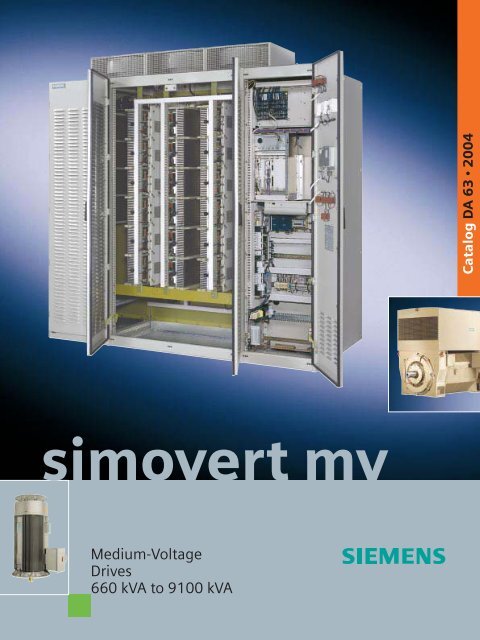
SIMOVERT MV Medium-Voltage Drives 660 kVA to 9100 ... - Industry
SIMOVERT MV Medium-Voltage Drives 660 kVA to 9100 ... - Industry
SIMOVERT MV Medium-Voltage Drives 660 kVA to 9100 ... - Industry

You also want an ePaper? Increase the reach of your titles
YUMPU automatically turns print PDFs into web optimized ePapers that Google loves.
Siemens DA 63 · 20040/3
0/4 Siemens DA 63 · 2004
<strong>SIMOVERT</strong> <strong>MV</strong>Overview11/2 Applications1/2 ¦ Innovative standard solutionsfor all applications¦ <strong>SIMOVERT</strong> <strong>MV</strong>: The flexible, modularand high-performance solution¦ <strong>SIMOVERT</strong> <strong>MV</strong>: The all-rounder1/3 ¦ <strong>SIMOVERT</strong> <strong>MV</strong>: The international solution¦ Focus on cus<strong>to</strong>mer benefits¦ <strong>SIMOVERT</strong> <strong>MV</strong>: Quality and environmentalresponsibility1/4 ¦ <strong>SIMOVERT</strong> <strong>MV</strong> drive convertersand H-compact, H-compact PLUShigh-voltage mo<strong>to</strong>rs:Optimally harmonized with one another1/5 Examples of order numbers1/5 <strong>SIMOVERT</strong> <strong>MV</strong> drive converter1/5 H-compact mo<strong>to</strong>rs1/6 H-compact PLUS mo<strong>to</strong>rsSiemens DA 63 · 2004 1/1
1<strong>SIMOVERT</strong> <strong>MV</strong>OverviewApplicationsInnovative standard solutionsfor all applications<strong>SIMOVERT</strong> <strong>MV</strong> ® are voltagesourceDC link drive convertersusing three-level technology.They convert the three-phasesystem line supply with fixedvoltage and fixed frequency, in<strong>to</strong>a three-phase system withvariable voltage and variablefrequency. The fully-digital,open-loop control technologyand the high-performance Vec<strong>to</strong>rControl with the innovativepower semiconduc<strong>to</strong>rs HV-IGBT (High-<strong>Voltage</strong> InsulatedGate Bipolar Transis<strong>to</strong>r) on theinverter side and a twelve-pulsediode rectifier on the line side inthe standard version guaranteehigh reliability, flexibility, securityof investment for the future,low harmonics fed back in<strong>to</strong> theline supply and low mo<strong>to</strong>rstressing.<strong>SIMOVERT</strong> <strong>MV</strong>The flexible, modular andhigh-performance solutionThe design of this standardseries is consistently modular.Thanks <strong>to</strong> its flexibility, it fulfillsalmost every cus<strong>to</strong>mer requirement.<strong>SIMOVERT</strong> <strong>MV</strong> is availablefor the most importantstandard mo<strong>to</strong>r voltages,2.3 kV, 3.3 kV, 4.16 kV, 6 kVand 6.6 kV. The standardizedoutput range extends from0.66 <strong>MV</strong>A <strong>to</strong> 9.1 <strong>MV</strong>A(dependent on the rated mo<strong>to</strong>rvoltage) with air and water cooling– higher outputs are availableon request.<strong>SIMOVERT</strong> <strong>MV</strong>: The all-rounder<strong>SIMOVERT</strong> <strong>MV</strong> can be usedfor an extremely wide range ofapplications.In waterworks, district heatingstations and water treatmentplants:Pumps for drinking water recoveryand distribution, pumpsfor heating circuits, slurrypumps.In the oil and natural gasindustry:Pumps and compressorsIn machinery construction:Fans, pumps and constant<strong>to</strong>rquedrivesIn the foodstuff industry:Centrifugal drives (e.g. in thesugar industry), pumps, kneaders,mixers, mills, extrudersIn marine engineering:Propeller drives, bow thrusters,lateral thrustersIn the cement industry:Conveyor belts, blowers andcrushersIn open-pit mining:Conveyor belt systems, vibra<strong>to</strong>rs,excava<strong>to</strong>rs, crushersIn wire and fine rolling mills:Wire-drawing drivesIn power utilities:Pumps, blowers, coal crushersIn the paper industry:Refiners, pumpsFig. 1/1Innovative HV-IGBT power semiconduc<strong>to</strong>r(High-<strong>Voltage</strong> Insulated Gate Bipolar Transis<strong>to</strong>r)Fig. 1/2Service-friendly using a modular design: Easily replaceable Power-Cards1/2 Siemens DA 63 · 2004
<strong>SIMOVERT</strong> <strong>MV</strong>Overview 1Applications<strong>SIMOVERT</strong> <strong>MV</strong>: The international solution<strong>SIMOVERT</strong> <strong>MV</strong> is not only availablefor the most importantinternational medium-voltagelevels, but also for the mostimportant international standards,such as:Further, <strong>SIMOVERT</strong> <strong>MV</strong> isoptionally available for marineapplications according <strong>to</strong> therequirements of the followingclassification societies (withcertificate, if desired):¦ IEC¦ American Bureau of¦ ENShipping¦ DIN VDE¦ Bureau Veritas¦ Det Norske Veritas¦ Germanischer Lloyd¦ Lloyds Register of Shipping¦ Chinese ClassificationSocietyFocus on cus<strong>to</strong>merbenefitsWith the <strong>SIMOVERT</strong> <strong>MV</strong> drivesystem, the main focus is oncus<strong>to</strong>mer benefits. The optimumdrive solution can alwaysbe found as a result of standardizedtechnology, a perfectlyharmonized system comprising<strong>SIMOVERT</strong> <strong>MV</strong> and theH-compact and H-compact-PLUS mo<strong>to</strong>rs and an extremelycomprehensive range of accessories.<strong>SIMOVERT</strong> <strong>MV</strong>:Quality and environmentalresponsibility<strong>SIMOVERT</strong> <strong>MV</strong> drive convertersare manufactured according <strong>to</strong>the highest quality standards.The complete manufacturingprocess, i.e. development,mechanical design, production,contract administration andlogistics supply center andsales/marketing have been certifiedfrom an independent bodyaccording <strong>to</strong> DIN ISO 9001.It goes without saying that<strong>SIMOVERT</strong> <strong>MV</strong> fulfills all of theimportant criteria for environmentalprotection.Fig. 1/3Mounting rack of the Vec<strong>to</strong>r ControlFig. 1/4Optional single-phase uninterruptible power supply (UPS) withMASTERGUARD (option L17)Siemens DA 63 · 2004 1/3
1<strong>SIMOVERT</strong> <strong>MV</strong>OverviewApplications<strong>SIMOVERT</strong> <strong>MV</strong> drive converters and H-compact, H-compact PLUS high-voltage mo<strong>to</strong>rs:Optimally harmonized with one anotherThe <strong>SIMOVERT</strong> <strong>MV</strong> drive The self-ventilated, rib-cooledconverters <strong>to</strong>gether with the mo<strong>to</strong>rs H-compact (1LA4) arewell-proven H-compact and available in an output rangeH-compact PLUS high-voltage from 0.8 MW <strong>to</strong> 3.6 MW. Theymo<strong>to</strong>rs form a high-performancedrive package over a applications where highoffer significant advantages forwide output and speed range. <strong>to</strong>rques are demanded even atDuring development, the drive low speeds. If the requirementsconverter and mo<strong>to</strong>r were alwaysconsidered as a single en-the force-ventilated versionare even more stringent, thentity, and were harmonized with (1PQ4) provides <strong>to</strong>rques whichone another both from the perspectiveof cost-effectiveness rated mo<strong>to</strong>r <strong>to</strong>rque over a wideare almost the same as theas well as technically. This is the speed control range.reason why a filter is not requiredbetween the drive converterand the mo<strong>to</strong>r. The mo<strong>to</strong>rsare extremely rugged,which means that they can besimply operated under even the<strong>to</strong>ughest application conditions.H-compact PLUS high-voltagemo<strong>to</strong>rs (shaft height from450 mm <strong>to</strong> 630 mm) cover anoutput range from 0.7 MW <strong>to</strong>7 MW. The mo<strong>to</strong>rs have a modulardesign and are availablewith three cooling types:¦ open-circuit cooling (1RA4),¦ air-<strong>to</strong>-water cooling (1RN4)and¦ air-<strong>to</strong>-air cooling (1RQ4).As a result of this variable coolingconcept, the drives can beintegrated in<strong>to</strong> any plant orsystem configuration.The mo<strong>to</strong>rs are characterizedby superb output, reliability andefficiency. This is mainlyachieved as follows:¦ Excellent operating data,expecially when it comes <strong>to</strong>efficiency and power fac<strong>to</strong>r¦ High power density¦ Compact type ofconstruction¦ Stiff rugged enclosure andbearing endshields manufacturedout of cast iron¦ All parts are providedwith long-term corrosionprotection¦ MICALASTIC high voltageinsulation using VPItechnology (VacuumPressure Impregnation)1/4 Siemens DA 63 · 2004
<strong>SIMOVERT</strong> <strong>MV</strong>Overview 1Examples of order numbers<strong>SIMOVERT</strong> <strong>MV</strong> drive converter6SE80 <strong>SIMOVERT</strong> <strong>MV</strong> drive converterOutput in 100 <strong>kVA</strong>Cooling type1 Air cooling2 Water coolingRated supply voltageA 2.3 kVB3.3 kVC 4.16 kVD6.0 kVE 6.6 kVVersionA Drive converter with 12-pulse diode inputFunction releaseClosed-loop control related versionOptionsAll of the options provided in the drive converter are listed here and specifiedwith a supplementary code; options may have <strong>to</strong> be specified in plain texte.g. 6 S E 8 0 1 5 – 1 B A 0 1 – ZH-compact mo<strong>to</strong>rsH-compact mo<strong>to</strong>rs1LA4 self-ventilated1PQ4 force-ventilatedFrame size, coded (shaft height, output stage)No. of poles (2, 4, 6, 8)Ro<strong>to</strong>r version<strong>SIMOVERT</strong> <strong>MV</strong> drive convertere.g. 1 L A 4 4 5 0 – 2 C V 0 0 – Z<strong>Voltage</strong> code0 2.3 kV / 50 Hz1 2.3 kV / 60 Hz2 3.3 kV / 50 Hz3 3.3 kV / 60 Hz4 4.16 kV / 50 Hz5 4.16 kV / 60 HzType of construction code0 IM B34 IM V1 with protective roof assembly8 IM V1 without protective roof assemblySpecial versionsSpecify a code and, if required, describe in plain textSiemens DA 63 · 2004 1/5
1<strong>SIMOVERT</strong> <strong>MV</strong>OverviewExamples of order numbersH-compact PLUS mo<strong>to</strong>rse.g. 1 R A 4 5 6 0 – 8 H V 2 0 – ZH-compact PLUS mo<strong>to</strong>rs1RA4 open-circuit ventilated1RN4 with air/water cooler1RQ4 with air/air coolerFrame size, coded (shaft height, output stage)No. of poles (4, 6, 8)Cooling typeF Version with separately-driven fanIP55/IC86W (1RN4)H Basic version with shaft-mounted fanIP23/IC01 (1RA4) and IP55/IC81W (1RN4)J Basic version with shaft-mounted fan, internal and externalIP55/IC611 (1RQ4)<strong>SIMOVERT</strong> <strong>MV</strong> drive converter<strong>Voltage</strong> code0 2.3 kV / 50 Hz1 2.3 kV / 60 Hz2 3.3 kV / 50 Hz3 3.3 kV / 60 Hz4 4.16 kV / 50 Hz5 4.16 kV / 60 HzType of construction code0 IM B34 IM V1 with protective roof assembly (1RQ4)8 IM V1 without protective roof assembly (1RA4/1RN4)Special versionsSpecify a code and, if required, describe in plain text1/6 Siemens DA 63 · 2004
<strong>SIMOVERT</strong> <strong>MV</strong>Systemdescription2/2 Technical features2/2 ¦ Line supply¦ Incoming transformer2/3 ¦ Drive converter– Innovative HV-IGBT power semiconduc<strong>to</strong>rs– Opera<strong>to</strong>r control of the drive converter– Power section design2/4 – Low mo<strong>to</strong>r stressing using athree-level circuit design¦ Mo<strong>to</strong>rs22/6 Open and closed-loop control functions2/6 ¦ Closed-loop control features¦ Software functions2/7 Opera<strong>to</strong>r control and diagnostics2/7 ¦ OP7 opera<strong>to</strong>r panel¦ Control terminal strip¦ PROFIBUS DP2/8 ¦ Integration of drives in<strong>to</strong> SIMATIC ® S7with Drive ES– Drive ES Basic features– Functions of the blocks from Drive ES SIMATIC– Overview “Software environment for<strong>SIMOVERT</strong> <strong>MV</strong>”Siemens DA 63 · 2004 2/1
2<strong>SIMOVERT</strong> <strong>MV</strong>System descriptionTechnical featuresLine supply Incoming transformer Drive converter<strong>SIMOVERT</strong> <strong>MV</strong> drives keep theline supply stressing low:The <strong>SIMOVERT</strong> <strong>MV</strong> drive converteris connected <strong>to</strong> the¦ The starting current is limited medium-voltage line supply<strong>to</strong> the rated currentthrough a drive converter transformer.For the standard¦ There is only a low harmonic12-pulse DFE, a three-windingcomponent in the line currenttransformer is required, anddue <strong>to</strong> the 12-pulse diodeone five-winding transformer orrectifier DFE (Diode Fronttwo three-winding transformersEnd) used as standardfor the optional 24-pulse DFE(see Page 6/17).¦ Low reactive power drawn(cos j 1 > 0.96)¦ Optional 24-pulse diode rectifierfor applications wherethe harmonics fed back in<strong>to</strong>the line supply must be keptas low as possibleThe <strong>SIMOVERT</strong> <strong>MV</strong> drive (driveconverter and mo<strong>to</strong>r) is decoupledfrom the line supplythrough a transformer, resultingin:¦ Defined short-circuit power¦ Floating mo<strong>to</strong>r operationpossible¦ Low harmonics as a result ofthe 12-pulse DFE.¦ Output range:– for air cooling<strong>660</strong> <strong>to</strong> 7200 <strong>kVA</strong>;– for water cooling:1000 <strong>to</strong> <strong>9100</strong> <strong>kVA</strong>– higher outputs on request¦ Available for standardizedmedium voltage levels of2.3 kV, 3.3 kV, 4.16 kV, 6 kVand 6.6 kV¦ Ready-<strong>to</strong>-connect cabinetunit with degree of protectionIP21¦ Compact, modular design,hence extremely reliable andeasy <strong>to</strong> service¦ Standardized output rangefor air- and water cooling¦ The open-loop and closedlooppower supply is electricallyisolated from the powersection¦ Short-circuit proof driveconverter output (withoutsupplementary measures)¦ Fully-digital open- andclosed-loop control using afast signal processor¦ Vec<strong>to</strong>r Control with excellentcontrol performance¦ Frequency and speed controlrange up <strong>to</strong> 1:1000 (withencoder)¦ Speed resolution in the permille range (with encoder)¦ The drive is operated andmoni<strong>to</strong>red via the localopera<strong>to</strong>r panel, via a PC withthe engineering system<strong>Drives</strong> ES, via the controlterminal strip from a centralcontrol room or viaPROFIBUS DP from a higherlevelsupervisory processcontrol system¦ Opera<strong>to</strong>r prompting andmessages from the driveconverter are displayed inplain text on the opera<strong>to</strong>rpanel¦ Communications-capable inthe au<strong>to</strong>mation environmentvia PROFIBUS DP¦ The circuit-breaker iscontrolled from the driveconverter.6 kV / 6.6 kV<strong>660</strong> <strong>kVA</strong> 2000 <strong>kVA</strong>4.16 kV1300 <strong>kVA</strong> 7200 <strong>kVA</strong>3.3 kV1000 <strong>kVA</strong> 3100 <strong>kVA</strong>2.3 kV800 <strong>kVA</strong> 2400 <strong>kVA</strong>Air cooling4.16 kV1700 <strong>kVA</strong> <strong>9100</strong> <strong>kVA</strong>3.3 kV1300 <strong>kVA</strong> 4000 <strong>kVA</strong>2.3 kV1000 <strong>kVA</strong> 2600 <strong>kVA</strong>Water coolingFig. 2/1<strong>SIMOVERT</strong> <strong>MV</strong> drive converter output range2/2 Siemens DA 63 · 2004
<strong>SIMOVERT</strong> <strong>MV</strong>System descriptionTechnical featuresInnovative HV-IGBTpower semiconduc<strong>to</strong>rsThe IGBT (Insulated GateBipolar Transis<strong>to</strong>r) has establisheditself as a standard inlow-voltage drive technology.A new generation has beencreated by consequentiallydeveloping the device for ahigher blocking capability and ahigher current-carrying capacity:The HV-IGBT (High-<strong>Voltage</strong>-IGBT).Advantages of HV-IGBT devicesover conventional IGCTthyris<strong>to</strong>rs (Integrated GateCommutated Thyris<strong>to</strong>r):¦ The HV-IGBT can be controlledby just using the voltageapplied <strong>to</strong> the gate¦ Together with the gating circuit,current and voltage transientscan be influencedduring turn-on and turn-off.¦ Overvoltages caused by parasiticleakage inductanceswhen the HV-IGBT is turnedoff are limited by the HV-IGBTin conjunction with the gatingcircuit¦ The turn-on characteristics ofthe HV-IGBT can be optimallyadapted <strong>to</strong> the free-wheelingdiode: the diode turns off inthe safe operating range¦ The HV-IGBT does notrequire any snubber circuitry,thus resulting in a simpledesign, high utilization leveland a high degree of reliabilityof the drive converter¦ The required gating power islow¦ HV-IGBTs limit, <strong>to</strong>gether withthe gating circuit, short-circuitcurrents without anyother circuitry required.This means that the<strong>SIMOVERT</strong> <strong>MV</strong> drive converterhas a short-circuitproof output.Opera<strong>to</strong>r controlof the drive converterThe important control elements<strong>to</strong> operate the drive converteras well as measured value andstatus displays are combined inthe OP7 opera<strong>to</strong>r panel.With the help of the optionalsoftware Drive ES (Drive EngineeringSystem), parameterizationbecomes particularly easyand user-friendly.Installed <strong>to</strong> a standard hardwareplatform (PC or programmingunit PG), Drive ES alsoguarantees permanent provisionof au<strong>to</strong>mation and drivedata of a project in the STEP 7Manager.Further, the drive converter andthe drive can be centrally controlledfrom a control room.A control terminal strip is providedfor this purpose. All of therequired control- and measuredvalue signals can beconnected here or retrievedfrom here.Beyond this, the drive convertercan be integrated in<strong>to</strong> a higherlevelsupervisory process controlsystem. Communicationsbetween the external controland drive converter are realizedvia the serial PROFIBUS DPinterface.Power section designThe power section of the<strong>SIMOVERT</strong> <strong>MV</strong> drive converterconsists, as standard of the following:¦ 12-pulse diode rectifier (DFE)¦ Three-level voltage DC linkwith capaci<strong>to</strong>rs and crowbarthyris<strong>to</strong>r¦ Three-level inverter with threephase unitsThe power section design utilizingthree-level technology hasmany advantages:¦ The HV-IGBTs are onlystressed with half of the DClink voltage¦ For the same quality of theoutput current, the switchingfrequency is only approximately1/4 of that required for2-level technology; thus, theHV-IGBT losses are lowerand the efficiency isincreased¦ Improved output currentcharacteristic in comparison<strong>to</strong> two-level designs: Thelosses in the mo<strong>to</strong>r and thesound pressure level arelower.2IncomingrectifierDC voltagelinkThree-levelinverterFig. 2/2Power section block diagramSiemens DA 63 · 2004 2/3
<strong>SIMOVERT</strong> <strong>MV</strong>System descriptionTechnical featuresPower section design (continued)2Fig. 2/3Modular and service-friendly:Air-cooled HV-IGBT Power-Cardof the mo<strong>to</strong>r-side drive converterFig. 2/4Modular and service-friendly:Water-cooled HV-IGBT Power-Cardof the mo<strong>to</strong>r-side drive converterLoad currentLow mo<strong>to</strong>r stressing using athree-level circuit designThe mo<strong>to</strong>r-side inverter utilizesa three-level circuit design. Thisresults, <strong>to</strong>gether with the propertiesof the HV-IGBT, in anessentially sine-wave outputcurrent. The low harmoniccomponent guarantees an excellentconstant <strong>to</strong>rque with respect<strong>to</strong> time over the completespeed control range and lowmo<strong>to</strong>r losses. Fig. 2/5<strong>SIMOVERT</strong> <strong>MV</strong> output current (current fundamental fac<strong>to</strong>r, typical g = 99%)Mo<strong>to</strong>rsWhen developing the<strong>SIMOVERT</strong> <strong>MV</strong> drive system,the mo<strong>to</strong>rs were involved in theoverall design concept rightfrom the very start. Thus, the<strong>SIMOVERT</strong> <strong>MV</strong> drive convertersand the Siemens standardH-compact and H-compactPLUS mo<strong>to</strong>rs are optimally harmonizedwith one another, bothfrom the economic and technicalperspectives. They do notrequire a special output filter foran optimum cost-effective solution.With output frequencies of up<strong>to</strong> 100 Hz (higher frequencieson request), the drive convertersare also suitable for feedingfast directly-coupled drives.Using an IHV-filter or theoptional output filter the<strong>SIMOVERT</strong> <strong>MV</strong> drive converterscan feed any other mediumvoltage,third-party inductionmo<strong>to</strong>r:This means that fixed-speedmedium-voltage mo<strong>to</strong>rs can beretrofitted <strong>to</strong> become variablespeeddrives using a<strong>SIMOVERT</strong> <strong>MV</strong> drive converter.2/4 Siemens DA 63 · 2004
<strong>SIMOVERT</strong> <strong>MV</strong>System descriptionTechnical featuresLine supplyCircuit-breaker<strong>Medium</strong>-voltage circuit-breaker,converter-controlledDrive converter transformerThree-winding transformer <strong>to</strong> adapt the voltage<strong>to</strong> the medium-voltage line supply. It provides twovoltage systems, rotated through 30° electrical for12-pulse line-side operation and less harmonic effectson the supply2Line-side drive converterSeries circuit of 2 uncontrolled diode rectifiers in a threephasebridge circuit configuration <strong>to</strong> generate the DC linkvoltageDC link capaci<strong>to</strong>rsMaintenance-free and self-healing MKK capaci<strong>to</strong>rs ina parallel circuit configuration <strong>to</strong> smooth the DC linkvoltage. The number of capaci<strong>to</strong>rs depends on the driveconverter outputDC link DC voltage PTPT <strong>to</strong> sense the actual DC link voltageMo<strong>to</strong>r-side inverter3-phase units comprising the HV-IGBT anddiode Power-Cards.Combined electronic PT and CT on the mo<strong>to</strong>r sideCT/PT <strong>to</strong> sense the actual output voltages and mo<strong>to</strong>rcurrents Mo<strong>to</strong>rSquirrel-cage induction mo<strong>to</strong>r with a medium-voltagewindingFig. 2/6Block diagram of a <strong>SIMOVERT</strong> <strong>MV</strong> driveSiemens DA 63 · 2004 2/5
<strong>SIMOVERT</strong> <strong>MV</strong>System descriptionOpen- and closed-loop control functions2The field-oriented Vec<strong>to</strong>r Controlis used for the mo<strong>to</strong>r-sideclosed-loop control of the<strong>SIMOVERT</strong> <strong>MV</strong> voltage DC linkdrive converter.The Vec<strong>to</strong>r Control can eitherbe operated as closed-loopfrequency, speed or <strong>to</strong>rquecontrol.The Vec<strong>to</strong>r Control achievesthe same dynamic performanceas that of a DC drive.This is made possible by thefact that the <strong>to</strong>rque- and fluxgeneratingcurrent componentsare precisely controlled,independently of one another.Specified <strong>to</strong>rques can be preciselymaintained and limitedusing this vec<strong>to</strong>r control.In the speed control range 1:10,the field-oriented control of the<strong>SIMOVERT</strong> <strong>MV</strong> does not requirea speed encoder and isessentially independent of themo<strong>to</strong>r parameters.A speed encoder is required forthe following <strong>SIMOVERT</strong> <strong>MV</strong>applications:¦ High requirements are placedon the dynamic performance¦ Closed-loop <strong>to</strong>rque control/constant-<strong>to</strong>rque drives with acontrol range > 1:10¦ Lowest speeds¦ Highest speed accuracy.The various control versions arelisted in detail on Page 6/9.Closed-loop control features¦ Message system where plaintext messages are output onthe OP7 opera<strong>to</strong>r panel¦ Self-diagnostics of the controlhardware, e.g. memorytest¦ Multi-channel fast tracememory <strong>to</strong> record currentsand voltages for drive diagnostics¦ Non-volatile memory for reliablediagnostics, even if thepower supply fails¦ HV-IGBT modules are moni<strong>to</strong>redwith an individual signalfor mounting slot¦ Comfortable local opera<strong>to</strong>rcontrol via the OP7 opera<strong>to</strong>rpanel¦ Highly accurate and stableactual value sensing usingthe innovative sigma-deltatechnique for reliable driveconverter actual values (refer<strong>to</strong> Fig. 2/7).Fig. 2/7Actual mo<strong>to</strong>r currents and output voltages are precisely sensedusing a special, patented sigma-delta techniqueSoftware functionsThe basic software includes abroad scope of standard functions.These functions offermaximum ease of use and outstandingflexibility. Also, theyensure universal operatingconditions and a high degree ofoperational reliability andsafety.Setpoint inputSetpoints can be entered as thesum of main- and supplementarysetpoints as follows:¦ Internally: as fixed, mo<strong>to</strong>rizedpotentiometer- or jog setpoint¦ Externally: via the analoginputs, the serial interfaces orthe option modules.The fixed internal setpoints andthe mo<strong>to</strong>rized potentiometersetpoint can be changed-overor set from any of the interfacesvia control commands.Au<strong>to</strong>matic restart(option L32)This function au<strong>to</strong>maticallyrestarts a drive converter whenthe power returns after a shutdown due <strong>to</strong> power failure.Restart-on-the-fly circuit(option L31)The restart-on-the-fly circuitallows the drive converter <strong>to</strong> beswitched <strong>to</strong> a mo<strong>to</strong>r which isstill rotating.2/6 Siemens DA 63 · 2004
<strong>SIMOVERT</strong> <strong>MV</strong>System descriptionOpera<strong>to</strong>r control and diagnostics<strong>SIMOVERT</strong> <strong>MV</strong> drives can becontrolled and visualized at thedrive converter itself, or alsoexternally.OP7 opera<strong>to</strong>r panelThe <strong>SIMOVERT</strong> <strong>MV</strong> drive canbe locally controlled and moni<strong>to</strong>redusing the opera<strong>to</strong>r panelin the cabinet door.The assignment of the keys isdefined by the drive converter’ssoftware for open-loop andclosed-loop control. The followingfunctions can be selected:¦ Display drive actual values¦ Enter speed setpoints usingthe numerical keys¦ Read and delete messages¦ Preset two mo<strong>to</strong>r and setpointdata records¦ Preset jog setpoints¦ Menue-assisted functions forservice and commissioning.At the unit via¦ the standard OP7 opera<strong>to</strong>rpanel¦ a PC with the Drive ES engineeringsystemBy entering the necessaryparameters, the control modecan be set from remote <strong>to</strong>direct.The following actual values canbe displayed:¦ Speed¦ Mo<strong>to</strong>r voltage¦ Mo<strong>to</strong>r current¦ Mo<strong>to</strong>r output¦ cos j of the mo<strong>to</strong>r¦ DC link voltage¦ Operating timeThe messages and actual valuesare displayed on a liquidcrystaldisplay with 4 x 20digits. The plain-text display isin one of the following languages(as standard):¦ German¦ EnglishRemote control via¦ the control terminal strip¦ PROFIBUS DPFig. 2/8OP7 Opera<strong>to</strong>r panel2Control terminal stripThe drive converter includes acontrol terminal strip <strong>to</strong> controland moni<strong>to</strong>r the<strong>SIMOVERT</strong> <strong>MV</strong> drive from acontrol room. Both analog aswell as digital inputs andoutputs are available at thiscontrol terminal strip (refer <strong>to</strong>Page 6/10).PROFIBUS DP<strong>SIMOVERT</strong> <strong>MV</strong> is equipped asstandard with a PROFIBUS DPinterface <strong>to</strong> establish the couplingbetween the drive and thehigher-level au<strong>to</strong>mation system.Today, PROFIBUS DP isthe standard bus system forSiemens drive technology for allapplications at the field level.PROFIBUS DP is specified inthe European StandardEN 50170, Volume 2, andpermits cyclic data transferbetween the <strong>SIMOVERT</strong> <strong>MV</strong>units and the higher-levelsystem.In order that the drive can fulfillthe specific process task, itsparameters must be individuallyadapted during the commissioningphase. The Drive ESBasic engineering <strong>to</strong>ol is usedfor this purpose. The programallows the drive parameters<strong>to</strong> be handled in a structuredfashion when commissioningthe drive and when service isrequired. Drive ES communicatesdirectly with the<strong>SIMOVERT</strong> <strong>MV</strong> via theconnected PROFIBUS DP.Fig. 2/9Mounting rack with vec<strong>to</strong>r controlSiemens DA 63 · 2004 2/7
<strong>SIMOVERT</strong> <strong>MV</strong>6SE80 Drive Converters3/2 Design3/2 General technical data3/3 Rated data3/4 Air-cooled drive converters for 6.0 kV and 6.6 kV3/6 Water-cooled <strong>SIMOVERT</strong> <strong>MV</strong> drive converters3/8 Selection and ordering data3/8 <strong>SIMOVERT</strong> <strong>MV</strong> air-cooled drive converterswith 12-pulse diode input circuit (DFE)for constant and square-law load <strong>to</strong>rque3/10 <strong>SIMOVERT</strong> <strong>MV</strong> air-cooled drive converterswith 12-pulse diode input circuit (DFE)with sine-wave EMC output filter (option Y15)for square-law load <strong>to</strong>rque3/12 <strong>SIMOVERT</strong> <strong>MV</strong> air-cooled drive converterswith 12-pulse diode input circuit (DFE)for 6.0 and 6.6 kV with integrated high voltagefilter (IHV filter) for square-law load <strong>to</strong>rque3/14 <strong>SIMOVERT</strong> <strong>MV</strong> water-cooled drive converterswith 12-pulse diode inpyut circuit (DFE)for constant and square-law load <strong>to</strong>rque3/16 <strong>SIMOVERT</strong> <strong>MV</strong> water-cooled drive converterswith 12-pulse diode input circuit (DFE)with sine-wave EMC output filter (option Y15)for square-law load <strong>to</strong>rque33/18 Options3/18 Description of the optionsSiemens DA 63 · 2004 3/1
<strong>SIMOVERT</strong> <strong>MV</strong>6SE80 Drive ConvertersDesignGeneral technical dataPower componentsLine-side drive converter¦ Standard¦ OptionMo<strong>to</strong>r-side drive converterClosed-loop controlDrive quadrants¦ 12/24-pulse DFE¦ with the braking chopper and external brake resis<strong>to</strong>roptionDiodes / HV-IGBT12-pulse diode rectifier (DFE, Diode Front End)24-pulse diode rectifier (DFE)3-level drive converterVec<strong>to</strong>r Control, fully-digital with signal processor2 directions of rotation, mo<strong>to</strong>ring (2 quadrant)2 directions of rotation, mo<strong>to</strong>ring and braking (4 quadrant)3Electrical isolation of the power section– open- and closed-loop controlFiber-optic cableAuxiliary supply 3-ph./N/380 V/AC ±10%, 50/60 Hz ± 3%3-ph./N/400 V/AC ±10%, 50/60 Hz ± 3%3-ph./N/415 V/AC +6% –10%, 50/60 Hz ± 3%Optional: Auxiliary supply without loadable N conduc<strong>to</strong>r (Y75).Optional: Other auxiliary voltages (Y75).Air coolingPermissible ambient- andcoolant temperature and humidity rating¦ in operation¦ during s<strong>to</strong>rage¦ during transportWater coolingPermissible ambient temperature and humidity rating¦ in operation¦ during s<strong>to</strong>rage (without de-ionized water)¦ during transport (without de-ionized water)Permissible coolant temperature(raw, unconditioned water)¦ inlet¦ outletInstallation altitudeForced air cooling using integrated fans0 °C <strong>to</strong> +40 °C: 100% load capacity, relative air humidity ˆ 85% (moisture condensationis not permissible), otherwise corresponds <strong>to</strong> 3K3 acc. <strong>to</strong> IEC 60721-3-3+40 °C <strong>to</strong> +45 °C: current de-rating, refer <strong>to</strong> Fig. 6/3–25 °C <strong>to</strong> +55 °C: relative air humidity ˆ 95%, otherwise corresponds <strong>to</strong>1K2 acc. <strong>to</strong> IEC 60721-3-1–25 °C <strong>to</strong> +70 °C: relative air humidity ˆ 95%, otherwise corresponds <strong>to</strong>2K2 acc. <strong>to</strong> IEC 60721-3-2With integrated water-<strong>to</strong>-water cooling unit+5 °C <strong>to</strong> +40 °C: 100% load capacity, relative air humidity ˆ 85% (moisture condensationis not permissible), otherwise corresponds <strong>to</strong> 3K3 acc. <strong>to</strong> IEC 60721-3-3-25 °C <strong>to</strong> +55 °C: relative air humidity ˆ 95%, otherwise corresponds <strong>to</strong>1K2 acc. <strong>to</strong> IEC 60721-3-1-25 °C <strong>to</strong> +70 °C: relative air humidity ˆ 95%, otherwise corresponds <strong>to</strong>2K2 acc. <strong>to</strong> IEC 60721-3-2+5 °C <strong>to</strong> +35 °Cmax. +40 °Cˆ 1000 m above sea level: 100% load capability> 1000 m <strong>to</strong> 5000 m above sea level: Current de-rating, refer <strong>to</strong> Fig. 6/4> 2000 m <strong>to</strong> 5000 m above sea level: additional voltage de-rating, refer <strong>to</strong> Fig. 6/5Insulation Degree of pollution 2 acc. <strong>to</strong> DIN VDE 0110, Part 1Moisture condensation is not permissibleDegree of protection¦ Standard¦ OptionsAcc. <strong>to</strong> DIN VDE 0470, IEC 60 529, EN 60 529IP21 (air cooling), IP23 (water cooling)Refer <strong>to</strong> Page 3/19Protective class Class 1 in accordance with DIN VDE 0106, Part 1Shock hazard protection Acc. <strong>to</strong> DIN VDE 0106 Part 100 (VGB 4) and DIN VDE 0113 Part 1Radio interference suppression acc. <strong>to</strong> EN 61 800-3No radio interference suppressionPaint finish/color For indoor use/gray RAL 7032Mechanical strengthStandardFor stationary applications¦ deflection¦ accelerationDuring transport¦ deflection¦ accelerationAcc. <strong>to</strong> DIN IEC 60 068-2-60.075 mm in the frequency range 10 Hz <strong>to</strong> 58 Hz9.8 ms -2 (1 x g) in the frequency range > 58 Hz <strong>to</strong> 500 Hz3.5 mm in the frequency range 5 Hz <strong>to</strong> 9 Hz9.8 ms -2 (1 x g) in the frequency range > 9 Hz <strong>to</strong> 500 HzIncreased strength for option M66:Suitable for marine duty3/2 Siemens DA 63 · 2004
<strong>SIMOVERT</strong> <strong>MV</strong>6SE80 Drive ConvertersDesignGeneral technical dataThe <strong>SIMOVERT</strong> <strong>MV</strong> voltagesourceDC link drive convertershave rated outputs from <strong>660</strong> <strong>to</strong><strong>9100</strong> <strong>kVA</strong> and are available asready-<strong>to</strong>-connect cabinet unitswith degree of protection IP21(air cooling) or IP23 (watercooling).The modular design not onlymakes <strong>SIMOVERT</strong> <strong>MV</strong> extremelycompact, but alsoextremely service-friendly andenhances its availability. Componentsand parts are replacedin just a few minutes.When designing the equipment,special significance wasplaced on the modular design.For that reason, the <strong>SIMOVERT</strong><strong>MV</strong> converter can be easilyadapted for various requirementsand allows for inexpensive,cus<strong>to</strong>mized drive solutions.3Fig. 3/1Air-cooled drive converter <strong>SIMOVERT</strong> <strong>MV</strong> 6SE80Rated dataRated mo<strong>to</strong>r voltage 2.3 kV 3.3 kV 4.16 kV 6 kV 6.6 kVDrive convertersupply voltage 1 )2 × 1.2 kV 2 × 1.7 kV 2 × 2.2 kV 3 ) 2 × 1.2 kV 2 × 1.2 kVSupply voltage <strong>to</strong>lerance 2 ) – 10% – 10% – 10% – 10% – 10%Line supply frequency 50/60 Hz – 3% 50/60 Hz – 3% 50/60 Hz – 3% 50/60 Hz – 3% 50/60 Hz – 3%Line supply power fac<strong>to</strong>r,basic fundamental > 0.96 > 0.96 > 0.96 > 0.96 > 0.96Max. output frequency (standard)Higher frequencies, optional100 Hzup <strong>to</strong> 125 Hz100 Hzup <strong>to</strong> 125 Hz100 Hzup <strong>to</strong> 125 Hz66 Hz–66 Hz–Closed-loop control related properties (typical values)Speed accuracy 4 )n > 10%n < 5%in the field-weakening rangeTorque accuracyin the constant flux rangein the field-weakening rangeTorque rise time0.4 × f slipf slipf max /f rated × f slip /32.5%for n > 10 %5%approx. 5 msfor n >10%0.4 × f slipf slipf max /f rated × f slip /32.5%for n > 10%5%approx. 5 msfor n >10%0.4 × f slipf slipf max /f rated × f slip /32.5%for n > 10%5%approx. 5 msfor n >10%0.4 × f slipf slip–2.5%for n > 10%–approx. 8 msfor n >10%Torque ripple 2% 2% 2% 2% 2%0.4 × f slipf slip–2.5%for n > 10%–approx. 8 msfor n >10%1) The drive converter supplyvoltage corresponds <strong>to</strong> thesecondary no-load voltage ofthe transformer.2) –20% <strong>to</strong>lerance of the driveconverter input voltage in accordancewith the de-rated output.3) Outputs > 4000 <strong>kVA</strong>require 2 × 2 × 2.2 kV infeeds.4) These values are valid withoutspeed encoder and over anaverage of 10 s.Siemens DA 63 · 2004 3/3
<strong>SIMOVERT</strong> <strong>MV</strong>6SE80 Drive ConvertersDesignAir-cooled drive converters for 6.0 kV and 6.6 kV (continued)This has the followingbenefits:Retrofit applicationsExisting fixed speed mo<strong>to</strong>rsturn <strong>to</strong> variable-speed driveswhen converters are added:¦ The existing mo<strong>to</strong>r is suitablefor converter-fed operationwithout derating, because there is no additional loss inthe mo<strong>to</strong>r.¦ No mechanical changeoverat the driven machine isnecessary, e.g. adjustment ofthe shaft height, of thefoundation, of the coupling,the cooling system etc.¦ The existing mo<strong>to</strong>r cablesare preserved; no changesnecessary.¦ No supplementary outputchokes are necessary with long mo<strong>to</strong>r cables.New configurationsFig. 3/3Output voltage and current of the 6.0 and 6.6 kV <strong>SIMOVERT</strong> <strong>MV</strong> drive converter¦ Standard medium-voltagedrives can be put <strong>to</strong> usewithout extra measures andwithout derating.¦ It is possible <strong>to</strong> use standardpower cables for connectingthe mo<strong>to</strong>r.¦ No supplementary outputchokes are necessary withlong mo<strong>to</strong>r cables.Please refer <strong>to</strong> the notes onPage 6/13 for configuration of6.0kV/6.6kV drives.3Siemens DA 63 · 2004 3/5
<strong>SIMOVERT</strong> <strong>MV</strong>6SE80 Drive ConvertersDesign3Water-cooled drive convertersA water-<strong>to</strong>-water cooling unitis an integral part of the watercooled<strong>SIMOVERT</strong> <strong>MV</strong> driveconverter.The cooling unit is used <strong>to</strong> dissipatethe power loss from thedrive converter. It has an innerand an outer water circuit.The water of the outer circuitcools the inner circuit via theheat exchanger.The closed and vented innerwater circuit is filled with finewater. Fine water is de-ionizedwater with a very low conductivity.The water’s conductivitymust be low since the heat sink,through which the water flows,is on the same voltage level asthe HV-IGBT, and thus on thesame level as the DC link.Intake and outlet pipes are fittedbetween each phase stack.Cold water coming from thecooling unit flows in<strong>to</strong> the inletpipe, is heated-up by the powerloss in the HV-IGBT and thenreturns <strong>to</strong> the cooling unit viathe outlet pipe (see Fig. 3/7).A floor-mounted pan is installedin the drive converter cabinet inwhich, if there is a leak, the wateris collected. A leakage watermoni<strong>to</strong>ring function allows theleak <strong>to</strong> be quickly found if coolingwater is lost.Fig. 3/4<strong>SIMOVERT</strong> <strong>MV</strong> with water cooling (without cooling unit)Fig. 3/5Cooling unit (closed and open), in a special version with option W01 and stainless steel piping3/6 Siemens DA 63 · 2004
<strong>SIMOVERT</strong> <strong>MV</strong>6SE80 Drive ConvertersDesignThe water-cooled Power-Cardis a plug-in module just like theair-cooled Power-Card. If thePower-Card is <strong>to</strong> be replaced,the water circuit must beopened. This would mean thatair would enter the water circuitwhich would have <strong>to</strong> be subsequentlyvented. In order <strong>to</strong>avoid this, the Power-Cards areequipped with special connec<strong>to</strong>rs.These connec<strong>to</strong>rs preventair from entering the system.Thus, it is no longer necessary<strong>to</strong> subsequently vent thesystem, i.e. the drive converteris quickly operational again.3Fig. 3/6Water-cooled Power-Card with pipe connectionsRectifierInverterIntakeDischargeLeakage water moni<strong>to</strong>ringin the floor panelFig. 3/7Cooling of the drive converter power sectionSiemens DA 63 · 2004 3/7
<strong>SIMOVERT</strong> <strong>MV</strong>6SE80 Drive ConvertersSelection and ordering dataAir-cooled <strong>SIMOVERT</strong> <strong>MV</strong> drive converters with 12-pulse diode input circuit (DFE)for constant and square-law load <strong>to</strong>rqueRated drive Rated output Order No. Rated Base load Short- Input current Input Power loss 1 ) Efficiency 1 )converter at the mo<strong>to</strong>r output current 4 ) time at rated operatingvoltage at 50/60 Hz at 50/60 Hzoutput drive shaft current current 4 ) point3P N P , N , 0 , K , e V e P V h<strong>kVA</strong> kW A A A A kV kW %Rated mo<strong>to</strong>r voltage 2.3 kV800 640 6SE8008-1AA01 200 150 226 204 2 x 1.2 12 98.51000 810 6SE8010-1AA01 250 188 283 256 2 x 1.2 15 98.51200 980 6SE8012-1AA01 300 225 339 306 2 x 1.2 18 98.51400 1160 6SE8014-1AA01 350 263 396 360 2 x 1.2 20 98.61600 1320 6SE8016-1AA01 400 300 452 410 2 x 1.2 22 98.61800 1490 6SE8018-1AA01 450 338 509 460 2 x 1.2 25 98.72000 1<strong>660</strong> 6SE8020-1AA01 500 375 565 510 2 x 1.2 27 98.72200 1870 6SE8022-1AA01 550 413 622 560 2 x 1.2 29 98.72400 2040 6SE8024-1AA01 600 450 678 610 2 x 1.2 31 98.7Rated mo<strong>to</strong>r voltage 3.3 kV1000 810 6SE8010-1BA01 175 140 210 178 2 x 1.7 15 98.51300 1060 6SE8013-1BA01 230 184 276 235 2 x 1.7 20 98.51500 1240 6SE8015-1BA01 260 208 312 266 2 x 1.7 23 98.51800 1490 6SE8018-1BA01 315 252 378 320 2 x 1.7 27 98.62100 1730 6SE8021-1BA01 370 296 444 375 2 x 1.7 30 98.62300 1890 6SE8023-1BA01 400 320 480 408 2 x 1.7 33 98.62600 2150 6SE8026-1BA01 460 368 552 465 2 x 1.7 37 98.62900 2310 6SE8028-1BA01 510 408 612 515 2 x 1.7 41 98.63100 2560 6SE8031-1BA01 550 440 <strong>660</strong> 560 2 x 1.7 42 98.7Rated mo<strong>to</strong>r voltage 4.16 kV1300 1070 6SE8013-1CA01 180 135 203 184 2 x 2.2 20 98.51700 1410 6SE8017-1CA01 240 180 270 243 2 x 2.2 26 98.52000 1640 6SE8020-1CA01 280 210 316 284 2 x 2.2 30 98.52300 1890 6SE8023-1CA01 320 240 362 325 2 x 2.2 34 98.62600 2150 6SE8026-1CA01 360 270 407 370 2 x 2.2 37 98.62900 2400 6SE8028-1CA01 400 300 452 410 2 x 2.2 40 98.63300 2730 6SE8033-1CA01 460 345 520 470 2 x 2.2 46 98.63700 3060 6SE8037-1CA01 510 383 576 520 2 x 2.2 49 98.74000 3320 6SE8040-1CA01 550 413 622 562 2 x 2.2 51 98.7Rated mo<strong>to</strong>r voltage 2 x 4.16 kV 3 )4700 3900 6SE8047-1CA01 2 x 325 2 x 244 2 x 370 2 x 335 2 x 2 x 2.2 2 x 37 98.45200 4300 6SE8052-1CA01 2 x 360 2 x 270 2 x 410 2 x 370 2 x 2 x 2.2 2 x 40 98.55900 4900 6SE8058-1CA01 2 x 415 2 x 310 2 x 470 2 x 425 2 x 2 x 2.2 2 x 46 98.56700 5500 6SE8067-1CA01 2 x 460 2 x 345 2 x 520 2 x 470 2 x 2 x 2.2 2 x 49 98.67200 6000 6SE8072-1CA01 2 x 495 2 x 370 2 x 560 2 x 505 2 x 2 x 2.2 2 x 51 98.61) Without cooling system.2) Plus 18 A pre-charging current for 20 s.3) Drive converter with power section in parallel connection.4) Data valid for a load cycle with short time current 60 s, base load current500 s, with short time current/base load current = 150% / 100%.3/8 Siemens DA 63 · 2004
<strong>SIMOVERT</strong> <strong>MV</strong>6SE80 Drive ConvertersSelection and ordering dataAuxiliarypower req.[3/AC/N/400 V] 2 )Dimensions(with panels and doors)DimensiondrawingNo.WeightCoolingair req.Measuringsurfacesound press.levelMeasuringsurfacelevelCable cross-sectionfor line and mo<strong>to</strong>rsides max.Width Depth Height L pA L sA mm mm mm Page kg m 3 /s dB (A) dB (A) mm 2 per phase10 1818 1259 2570 7/2 1200 1.36 79 18 2 x 18510 2418 1259 2570 7/3 1750 1.66 79 18 2 x 18510 2418 1259 2570 7/3 1750 1.66 79 18 2 x 18510 2418 1259 2570 7/3 1800 1.66 79 18 2 x 18510 2418 1259 2570 7/3 1800 1.66 79 18 2 x 18510 2418 1259 2570 7/3 1850 1.66 79 18 3 x 18510 2418 1259 2570 7/3 1850 1.66 79 18 3 x 18514 2418 1259 2570 7/3 1900 1.79 80 18 3 x 18514 2418 1259 2570 7/3 1900 1.79 80 18 3 x 185314 1818 1259 2570 7/4 1500 1.90 81 18 2 x 18510 2418 1259 2570 7/5 2050 2.07 79 18 2 x 18514 2418 1259 2570 7/5 2050 2.63 80 18 2 x 18514 2418 1259 2570 7/5 2100 2.63 80 18 2 x 18514 2418 1259 2570 7/5 2100 2.63 80 18 2 x 18514 2418 1259 2570 7/5 2150 2.63 80 18 3 x 18514 2418 1259 2570 7/5 2150 2.63 80 18 3 x 18514 2418 1259 2570 7/5 2200 2.63 80 18 3 x 18514 2418 1259 2570 7/5 2200 2.63 80 18 3 x 18514 1818 1259 2570 7/4 1500 1.90 81 18 2 x 18510 2418 1259 2570 7/5 2050 2.07 79 18 2 x 18514 2418 1259 2570 7/5 2050 2.63 80 18 2 x 18514 2418 1259 2570 7/5 2100 2.63 80 18 2 x 18514 2418 1259 2570 7/5 2100 2.63 80 18 2 x 18514 2418 1259 2570 7/5 2150 2.63 80 18 3 x 18514 2418 1259 2570 7/5 2150 2.63 80 18 3 x 18520 2418 1259 2570 7/5 2200 2.90 83 18 3 x 18520 2418 1259 2570 7/5 2200 2.90 83 18 3 x 18538 4218 1259 2570 7/6 3600 5.80 86 19 3 x 18538 4218 1259 2570 7/6 3650 5.80 86 19 3 x 18538 4218 1259 2570 7/6 3650 5.80 86 19 3 x 18538 4218 1259 2570 7/6 3700 5.80 86 19 3 x 18538 4218 1259 2570 7/6 3700 5.80 86 19 3 x 185Siemens DA 63 · 2004 3/9
<strong>SIMOVERT</strong> <strong>MV</strong>6SE80 Drive ConvertersSelection and ordering dataAir-cooled <strong>SIMOVERT</strong> <strong>MV</strong> drive converters with 12-pulse diode input circuit (DFE)with sine-wave EMC output filter (option Y15) for square-law load <strong>to</strong>rqueRated drive Rated output Order No. Rated Input current Input Power loss 1 ) Efficiency 1 )converter at the mo<strong>to</strong>r with Order code +Y15 output current at rated voltage at 50/60 Hz at 50/60 Hzoutputdrive shaf<strong>to</strong>perating point3P N P , N , e V e P V h<strong>kVA</strong> kW A A kV kW %Rated mo<strong>to</strong>r voltage 2.3 kV<strong>660</strong> 550 6SE8008-1AA01-Z 165 169 2 x 1.2 16 97.6830 690 6SE8010-1AA01-Z 208 212 2 x 1.2 19 97.71000 830 6SE8012-1AA01-Z 250 256 2 x 1.2 22 97.81160 960 6SE8014-1AA01-Z 290 296 2 x 1.2 25 97.81330 1100 6SE8016-1AA01-Z 334 340 2 x 1.2 27 98.01500 1240 6SE8018-1AA01-Z 377 383 2 x 1.2 29 98.11<strong>660</strong> 1380 6SE8020-1AA01-Z 417 424 2 x 1.2 31 98.11830 1520 6SE8022-1AA01-Z 460 467 2 x 1.2 34 98.12000 1<strong>660</strong> 6SE8024-1AA01-Z 500 510 2 x 1.2 36 98.2Rated mo<strong>to</strong>r voltage 3.3 kV910 750 6SE8010-1BA01-Z 160 163 2 x 1.7 19 97.91180 980 6SE8013-1BA01-Z 206 210 2 x 1.7 24 98.01365 1130 6SE8015-1BA01-Z 239 243 2 x 1.7 28 97.91640 1360 6SE8018-1BA01-Z 287 292 2 x 1.7 32 98.01910 1590 6SE8021-1BA01-Z 334 340 2 x 1.7 35 98.22100 1740 6SE8023-1BA01-Z 367 373 2 x 1.7 38 98.22370 1970 6SE8026-1BA01-Z 415 422 2 x 1.7 41 98.32640 2190 6SE8028-1BA01-Z 462 470 2 x 1.7 46 98.32820 2340 6SE8031-1BA01-Z 493 500 2 x 1.7 47 98.3Rated mo<strong>to</strong>r voltage 4.16 kV1180 980 6SE8013-1CA01-Z 164 167 2 x 2.2 25 97.91550 1290 6SE8017-1CA01-Z 215 219 2 x 2.2 32 97.91820 1510 6SE8020-1CA01-Z 252 257 2 x 2.2 37 98.02090 1730 6SE8023-1CA01-Z 290 295 2 x 2.2 41 98.02370 1970 6SE8026-1CA01-Z 330 335 2 x 2.2 45 98.12640 2190 6SE8028-1CA01-Z 366 372 2 x 2.2 48 98.23000 2490 6SE8033-1CA01-Z 416 424 2 x 2.2 54 98.23370 2800 6SE8037-1CA01-Z 468 475 2 x 2.2 58 98.33640 3020 6SE8040-1CA01-Z 505 513 2 x 2.2 59 98.41) Without cooling system.2) Plus 18 A pre-charging current for 20 s.Note:Modifications of the Technical Data result in deviating rating data for mo<strong>to</strong>rand drive converter. When ordering, the plain text should include the ratedmo<strong>to</strong>r current, the mo<strong>to</strong>r current in the rated operating point and the mo<strong>to</strong>rno-load current.3/10 Siemens DA 63 · 2004
<strong>SIMOVERT</strong> <strong>MV</strong>6SE80 Drive ConvertersSelection and ordering dataAuxiliarypower req.[3/AC/N/400 V] 2 )Dimensions(with panels and doors)DimensiondrawingNo.WeightCoolingair req.Measuringsurfacesound press.levelMeasuringsurfacelevelCable cross-sectionfor line and mo<strong>to</strong>rsides max.Width Depth Height L pA L sA mm mm mm Page kg m 3 /s dB (A) dB (A) mm 2 per phase10 2718 1259 2570 7/2+7/10 2300 1.6 79 19 2 x 18510 3318 1259 2570 7/3+7/10 2850 1.9 79 19 2 x 18510 3318 1259 2570 7/3+7/10 3100 1.9 79 19 2 x 18510 3318 1259 2570 7/3+7/10 3150 1.9 79 19 2 x 18510 3318 1259 2570 7/3+7/10 3220 1.9 79 19 2 x 18510 3318 1259 2570 7/3+7/10 3270 1.9 79 19 3 x 18510 3318 1259 2570 7/3+7/10 3550 1.9 79 19 3 x 18514 3318 1259 2570 7/3+7/10 3600 2.1 80 19 3 x 18514 3318 1259 2570 7/3+7/10 3700 2.1 80 19 3 x 185314 2718 1259 2570 7/4+7/10 2850 2.2 81 19 2 x 18510 3318 1259 2570 7/5+7/10 3400 2.3 79 19 2 x 18514 3318 1259 2570 7/5+7/10 3450 2.9 80 19 2 x 18514 3318 1259 2570 7/5+7/10 3500 2.9 80 19 2 x 18514 3318 1259 2570 7/5+7/10 3730 2.9 80 19 2 x 18514 3318 1259 2570 7/5+7/10 3780 2.9 80 19 3 x 18514 3318 1259 2570 7/5+7/10 3990 2.9 80 19 3 x 18514 3318 1259 2570 7/5+7/10 4040 2.9 80 19 3 x 18514 3318 1259 2570 7/5+7/10 4100 2.9 80 19 3 x 18514 2718 1259 2570 7/4+7/10 3100 2.2 81 19 2 x 18510 3618 1259 2570 7/5+7/10 3690 2.3 79 19 2 x 18514 3618 1259 2570 7/5+7/10 3690 3.1 80 19 2 x 18514 3618 1259 2570 7/5+7/10 3740 3.1 80 19 2 x 18514 3618 1259 2570 7/5+7/10 4150 3.1 80 19 2 x 18514 3618 1259 2570 7/5+7/10 4200 3.1 80 19 3 x 18514 3618 1259 2570 7/5+7/10 4550 3.1 80 19 3 x 18520 3618 1259 2570 7/5+7/10 4600 3.1 83 19 3 x 18520 3618 1259 2570 7/5+7/10 4800 3.1 83 19 3 x 185Siemens DA 63 · 2004 3/11
<strong>SIMOVERT</strong> <strong>MV</strong>6SE80 Drive ConvertersSelection and ordering dataAir-cooled <strong>SIMOVERT</strong> <strong>MV</strong> drive converters with 12-pulse diode input circuit (DFE)with Integrated High <strong>Voltage</strong> filter (IHV filter) for square-law load <strong>to</strong>rqueRated drive Rated output Order No. Rated Input current InputPower loss 1 ) Efficiency 1 )converter at the mo<strong>to</strong>r output current at rated voltage at 50/60 Hz at 50/60 Hzoutputdrive shaf<strong>to</strong>perating point3P N P , N , e V e P V h<strong>kVA</strong> kW A A kV kW %Rated mo<strong>to</strong>r voltage 6.0 kV<strong>660</strong> 550 6SE8008-1DA01 65 170 2 x 1.2 17 97.51000 810 6SE8010-1DA01 95 257 2 x 1.2 25 97.61200 980 6SE8012-1DA01 115 310 2 x 1.2 30 97.61300 1080 6SE8013-1DA01 125 335 2 x 1.2 34 97.51500 1240 6SE8015-1DA01 145 387 2 x 1.2 39 97.51800 1490 6SE8018-1DA01 175 465 2 x 1.2 45 97.62000 1640 6SE8020-1DA01 190 515 2 x 1.2 50 97.6Rated mo<strong>to</strong>r voltage 6.6 kV<strong>660</strong> 550 6SE8008-1EA01 60 170 2 x 1.2 17 97.51000 810 6SE8010-1EA01 90 257 2 x 1.2 25 97.61200 980 6SE8012-1EA01 105 308 2 x 1.2 29 97.61300 1080 6SE8013-1EA01 116 335 2 x 1.2 33 97.51500 1240 6SE8015-1EA01 130 386 2 x 1.2 39 97.51800 1490 6SE8018-1EA01 160 463 2 x 1.2 44 97.62000 1640 6SE8020-1EA01 175 514 2 x 1.2 49 97.61) Without cooling system.2) Plus 18 A pre-charging current for 20 s.Note:Modifications of the Technical Data result in deviating rating data for mo<strong>to</strong>rand drive converter. When ordering, the plain text should include the ratedmo<strong>to</strong>r current, the mo<strong>to</strong>r current in the rated operating point and the mo<strong>to</strong>rno-load current.3/12 Siemens DA 63 · 2004
<strong>SIMOVERT</strong> <strong>MV</strong>6SE80 Drive ConvertersSelection and ordering dataAuxiliarypower req.[3/AC/N/400 V] 2 )Dimensions(with panels and doors)DimensiondrawingNo.WeightCoolingair req.Measuringsurfacesound press.levelMeasuringsurfacelevelCable cross-sectionfor line and mo<strong>to</strong>rsides max.Width Depth Height L pA L sA mm mm mm Page kg m 3 /s dB (A) dB (A) mm 2 per phase12 3018 1259 2570 7/7 4550 1.9 79 19 2 x 18512 3618 1259 2570 7/8 5500 2.2 79 19 2 x 18512 3618 1259 2570 7/8 5500 2.2 79 19 2 x 18512 3918 1259 2570 7/8 5600 2.2 79 19 2 x 18512 3918 1259 2570 7/8 5600 2.2 79 19 2 x 18512 4218 1259 2570 7/8 6450 3.2 81 19 3 x 18512 4218 1259 2570 7/8 6500 3.2 81 19 3 x 185312 3018 1259 2570 7/7 4550 1.9 79 19 2 x 18512 3618 1259 2570 7/8 5500 2.2 79 19 2 x 18512 3618 1259 2570 7/8 5500 2.2 79 19 2 x 18512 3918 1259 2570 7/8 5600 2.2 79 19 2 x 18512 3918 1259 2570 7/8 5600 2.2 79 19 2 x 18512 4218 1259 2570 7/8 6450 3.2 81 19 3 x 18512 4218 1259 2570 7/8 6500 3.2 81 19 3 x 185Siemens DA 63 · 2004 3/13
<strong>SIMOVERT</strong> <strong>MV</strong>6SE80 Drive ConvertersSelection and ordering dataWater-cooled <strong>SIMOVERT</strong> <strong>MV</strong> drive converters with 12-pulse diode input circuit (DFE)for constant and square-law load <strong>to</strong>rqueRated drive Rated output Order No. Rated Base load Short- Input current Input Power loss 1 ) Efficiency 1 )converter at the mo<strong>to</strong>r output current 5 ) time at rated operatingvoltage at 50/60 Hz at 50/60 Hzoutput drive shaft current current 5 ) point3P N P , N , 0 , K , e V e P V h<strong>kVA</strong> kW A A A A kV kW %Rated mo<strong>to</strong>r voltage 2.3 kV1000 810 6SE8010-2AA01 250 188 283 256 2 x 1.2 15 98.51200 980 6SE8012-2AA01 300 225 339 306 2 x 1.2 18 98.51400 1160 6SE8014-2AA01 350 263 396 360 2 x 1.2 20 98.61600 1320 6SE8016-2AA01 400 300 452 410 2 x 1.2 22 98.61800 1490 6SE8018-2AA01 450 338 509 460 2 x 1.2 25 98.72000 1<strong>660</strong> 6SE8020-2AA01 500 375 565 510 2 x 1.2 27 98.72200 1870 6SE8022-2AA01 550 413 622 560 2 x 1.2 29 98.72400 2040 6SE8024-2AA01 600 450 678 610 2 x 1.2 31 98.72600 2200 6SE8026-2AA01 650 467 700 662 2 x 1.2 34 98.7Rated mo<strong>to</strong>r voltage 3.3 kV1300 1060 6SE8013-2BA01 230 184 276 235 2 x 1.7 20 98.51500 1240 6SE8015-2BA01 260 208 312 266 2 x 1.7 23 98.51800 1490 6SE8018-2BA01 315 252 378 320 2 x 1.7 27 98.62100 1730 6SE8021-2BA01 370 296 444 375 2 x 1.7 30 98.62300 1890 6SE8023-2BA01 400 320 480 408 2 x 1.7 33 98.62600 2150 6SE8026-2BA01 460 368 552 465 2 x 1.7 37 98.62900 2310 6SE8028-2BA01 510 408 612 515 2 x 1.7 41 98.63100 2560 6SE8031-2BA01 550 440 <strong>660</strong> 560 2 x 1.7 42 98.73600 2950 6SE8036-2BA01 630 467 700 640 2 x 1.7 48 98.74000 3320 6SE8040-2BA01 700 467 700 710 2 x 1.7 54 98.7Rated mo<strong>to</strong>r voltage 4.16 kV1700 1410 6SE8017-2CA01 240 180 270 243 2 x 2.2 26 98.52000 1640 6SE8020-2CA01 280 210 316 284 2 x 2.2 30 98.52300 1890 6SE8023-2CA01 320 240 362 325 2 x 2.2 34 98.62600 2150 6SE8026-2CA01 360 270 407 370 2 x 2.2 37 98.62900 2400 6SE8028-2CA01 400 300 452 410 2 x 2.2 40 98.63300 2730 6SE8033-2CA01 460 345 520 470 2 x 2.2 46 98.63700 3060 6SE8037-2CA01 510 383 576 520 2 x 2.2 49 98.74000 3320 6SE8040-2CA01 550 413 622 562 2 x 2.2 51 98.74500 3700 6SE8045-2CA01 625 467 700 635 2 x 2.2 58 98.75000 4100 6SE8050-2CA01 700 467 700 710 2 x 2.2 65 98.7Rated mo<strong>to</strong>r voltage 2 x 4.16 kV 3 )5900 4900 6SE8058-2CA01 2 x 415 2 x 310 2 x 470 2 x 425 2 x 2 x 2.2 2 x 46 98.56700 5500 6SE8067-2CA01 2 x 460 2 x 345 2 x 520 2 x 470 2 x 2 x 2.2 2 x 49 98.67200 6000 6SE8072-2CA01 2 x 495 2 x 370 2 x 560 2 x 505 2 x 2 x 2.2 2 x 51 98.68000 6500 6SE8080-2CA01 2 x 555 2 x 420 2 x 630 2 x 565 2 x 2 x 2.2 2 x 58 98.6<strong>9100</strong> 7500 6SE8091-2CA01 2 x 630 2 x 420 2 x 630 2 x 640 2 x 2 x 2.2 2 x 65 98.71) Without cooling system.2) Plus 18 A pre-charging current for 20 s.3) Drive converter with power section in parallel connection.4) Raw water.5) Data valid for a load cycle with short time current 60 s, base load current500 s, with short time current/base load current = 150% / 100%.3/14 Siemens DA 63 · 2004
<strong>SIMOVERT</strong> <strong>MV</strong>6SE80 Drive ConvertersSelection and ordering dataLoss <strong>to</strong> theenvironmentAuxiliarypower req.[3/AC/N/400 V] 2 )Dimensions(with panels and doors)DimensiondrawingNo.WeightCoolingwaterrequired 4 )Measuringsurfacesoundpress. levelMeasuringsurfacelevelCable crosssectionfor lineand mo<strong>to</strong>r sidesmax.Width Depth Height L pA L skW A mm mm mm Page kg m 3 /h dB (A) dB (A) mm 2 per phase2.8 14 3018 1259 2280 7/11 2450 5.5 73 18 2 x 1853.1 14 3018 1259 2280 7/11 2450 5.8 73 18 2 x 1853.4 14 3018 1259 2280 7/11 2500 5.9 73 18 2 x 1853.7 14 3018 1259 2280 7/11 2500 6.1 73 18 2 x 1854.1 14 3018 1259 2280 7/11 2550 6.2 73 18 3 x 1854.5 14 3018 1259 2280 7/11 2550 6.4 73 18 3 x 1854.9 14 3018 1259 2280 7/11 2600 6.5 73 18 3 x 1855.4 14 3018 1259 2280 7/11 2600 6.7 73 18 3 x 1855.9 14 3018 1259 2280 7/11 2600 7.2 73 18 3 x 18532.8 14 3418 1259 2280 7/12 2800 8.7 73 18 2 x 1852.9 14 3418 1259 2280 7/12 2800 8.9 73 18 2 x 1853.2 14 3418 1259 2280 7/12 2850 9.2 73 18 2 x 1853.6 14 3418 1259 2280 7/12 2850 9.5 73 18 2 x 1853.8 14 3418 1259 2280 7/12 2900 9.7 73 18 3 x 1854.2 14 3418 1259 2280 7/12 2900 10.1 73 18 3 x 1854.7 14 3418 1259 2280 7/12 2950 10.3 73 18 3 x 1855.0 14 3418 1259 2280 7/12 2950 10.4 73 18 3 x 1855.8 14 3418 1259 2280 7/12 2950 10.8 73 18 3 x 1856.4 14 3418 1259 2280 7/12 2950 10.8 73 18 3 x 1853.2 14 3418 1259 2280 7/12 3000 9.2 73 18 2 x 1853.4 14 3418 1259 2280 7/12 3000 9.5 73 18 2 x 1853.8 14 3418 1259 2280 7/12 3050 9.8 73 18 2 x 1854.3 14 3418 1259 2280 7/12 3050 10.1 73 18 2 x 1854.5 14 3418 1259 2280 7/12 3100 10.3 73 18 3 x 1855.1 14 3418 1259 2280 7/12 3100 10.7 73 18 3 x 1855.6 14 3418 1259 2280 7/12 3150 11.0 73 18 3 x 1855.9 14 3418 1259 2280 7/12 3150 11.1 73 18 3 x 1856.7 14 3418 1259 2280 7/12 3150 11.9 73 18 3 x 1857.5 14 3418 1259 2280 7/12 3150 12.4 73 18 3 x 18510.1 20 5218 1259 2280 7/13 4450 21.4 76 19 3 x 18511.1 20 5218 1259 2280 7/13 4500 22.0 76 19 3 x 18511.8 20 5218 1259 2280 7/13 4500 22.3 76 19 3 x 18513.2 20 5218 1259 2280 7/13 4500 23.8 76 19 3 x 18515.0 20 5218 1259 2280 7/13 4500 24.8 76 19 3 x 185Siemens DA 63 · 2004 3/15
<strong>SIMOVERT</strong> <strong>MV</strong>6SE80 Drive ConvertersSelection and ordering dataWater-cooled <strong>SIMOVERT</strong> <strong>MV</strong> drive converters with 12-pulse diode input circuit (DFE)with sine-wave EMC output filter (option Y15) for square-law load <strong>to</strong>rqueRated drive Rated output Order No. Rated Input current Input Power loss 1 ) Efficiency 1 )converter at the mo<strong>to</strong>r with Order code +Y15 output current at rated voltage at 50/60 Hz at 50/60 Hzoutputdrive shaf<strong>to</strong>perating point3P N P , N , e V e P V h<strong>kVA</strong> kW A A kV kW %Rated mo<strong>to</strong>r voltage 2.3 kV1000 810 6SE8010-2AA01-Z 250 256 2 x 1.2 21 97.61200 980 6SE8012-2AA01-Z 300 306 2 x 1.2 25 97.91400 1160 6SE8014-2AA01-Z 350 360 2 x 1.2 28 98.01600 1320 6SE8016-2AA01-Z 400 410 2 x 1.2 31 98.11800 1490 6SE8018-2AA01-Z 450 460 2 x 1.2 33 98.22000 1<strong>660</strong> 6SE8020-2AA01-Z 500 510 2 x 1.2 36 98.22200 1870 6SE8022-2AA01-Z 550 560 2 x 1.2 39 98.22400 2040 6SE8024-2AA01-Z 600 610 2 x 1.2 41 98.3Rated mo<strong>to</strong>r voltage 3.3 kV1300 1060 6SE8013-2BA01-Z 230 235 2 x 1.7 27 97.91500 1240 6SE8015-2BA01-Z 260 267 2 x 1.7 31 97.91800 1490 6SE8018-2BA01-Z 315 320 2 x 1.7 35 98.12100 1730 6SE8021-2BA01-Z 370 375 2 x 1.7 39 98.12300 1890 6SE8023-2BA01-Z 400 410 2 x 1.7 43 98.12600 2150 6SE8026-2BA01-Z 460 465 2 x 1.7 46 98.22900 2310 6SE8028-2BA01-Z 510 516 2 x 1.7 51 98.23100 2560 6SE8031-2BA01-Z 550 560 2 x 1.7 54 98.3Rated mo<strong>to</strong>r voltage 4.16 kV1700 1410 6SE8017-2CA01-Z 240 243 2 x 2.2 35 97.92000 1640 6SE8020-2CA01-Z 280 284 2 x 2.2 41 98.02300 1890 6SE8023-2CA01-Z 320 325 2 x 2.2 45 98.02600 2150 6SE8026-2CA01-Z 360 370 2 x 2.2 49 98.12900 2400 6SE8028-2CA01-Z 400 410 2 x 2.2 53 98.23300 2730 6SE8033-2CA01-Z 460 470 2 x 2.2 60 98.23700 3060 6SE8037-2CA01-Z 510 522 2 x 2.2 64 98.34000 3320 6SE8040-2CA01-Z 550 565 2 x 2.2 66 98.41) Without cooling system.2) Plus 18 A pre-charging current for 20 s.3) Raw water.Note:Modifications of the Technical Data result in deviating rating data for mo<strong>to</strong>rand drive converter. When ordering, the plain text should include the ratedmo<strong>to</strong>r current, the mo<strong>to</strong>r current in the rated operating point and the mo<strong>to</strong>rno-load current.3/16 Siemens DA 63 · 2004
<strong>SIMOVERT</strong> <strong>MV</strong>6SE80 Drive ConvertersSelection and ordering dataLoss <strong>to</strong> theenvironmentAuxiliary Dimensionspower req.[3/AC/N/400 V] 2 )(with panels and doors)DimensiondrawingNo.WeightCoolingwaterrequired 3 )Measuringsurfacesound press.levelMeasuringsurfacelevelCable crosssectionfor lineand mo<strong>to</strong>r sidesmax.Width Depth Height L pA L skW A mm mm mm Page kg m 3 /h dB (A) dB (A) mm 2 per phase6.6 14 3918 1259 2280 7/11+7/15 3550 5.5 73 19 2 x 1857.0 14 3918 1259 2280 7/11+7/15 3800 5.8 73 19 2 x 1858.2 14 3918 1259 2280 7/11+7/15 3850 5.9 73 19 2 x 1858.9 14 3918 1259 2280 7/11+7/15 3920 6.1 73 19 2 x 1859.0 14 3918 1259 2280 7/11+7/15 3970 6.2 73 19 3 x 1859.1 14 3918 1259 2280 7/11+7/15 4250 6.4 73 19 3 x 1859.7 14 3918 1259 2280 7/11+7/15 4300 6.5 73 19 3 x 18510.5 14 3918 1259 2280 7/11+7/15 4400 6.7 73 19 3 x 18537.1 14 4318 1259 2280 7/12+7/15 4150 8.7 73 19 2 x 1857.4 14 4318 1259 2280 7/12+7/15 4200 8.9 73 19 2 x 1857.7 14 4318 1259 2280 7/12+7/15 4250 9.2 73 19 2 x 1858.8 14 4318 1259 2280 7/12+7/15 4480 9.5 73 19 2 x 1859.0 14 4318 1259 2280 7/12+7/15 4530 9.7 73 19 3 x 1859.1 14 4318 1259 2280 7/12+7/15 4740 10.1 73 19 3 x 1859.3 14 4318 1259 2280 7/12+7/15 4790 10.3 73 19 3 x 18510.0 14 4318 1259 2280 7/12+7/15 4850 10.4 73 19 3 x 1853.2 14 4618 1259 2280 7/12+7/15 4640 9.2 73 19 2 x 1859.0 14 4618 1259 2280 7/12+7/15 4640 9.5 73 19 2 x 18510.5 14 4618 1259 2280 7/12+7/15 4690 9.8 73 19 2 x 18510.9 14 4618 1259 2280 7/12+7/15 5100 10.1 73 19 2 x 18511.8 14 4618 1259 2280 7/12+7/15 5150 10.3 73 19 3 x 18512.0 14 4618 1259 2280 7/12+7/15 5500 10.7 73 19 3 x 18514.0 14 4618 1259 2280 7/12+7/15 5550 11.0 73 19 3 x 18514.5 14 4618 1259 2280 7/12+7/15 5750 11.1 73 19 3 x 185Siemens DA 63 · 2004 3/17
<strong>SIMOVERT</strong> <strong>MV</strong>6SE80 Drive ConvertersOptionsDescription of the optionsDescription of the option Comment Use with <strong>SIMOVERT</strong> <strong>MV</strong> in versionOrderCode2.3 kV3.3 kV4.16 kVair-cooled2 x 4.16 kVair-cooled6.0 kV6.6 kVair-cooled2 x 4.16 kV2.3 kV3.3 kV4.16 kVwatercooledwatercooled3Circuit versions / special optionsL01 24-pulse diode rectifierA 24-pulse diode rectifier can be used if harmonics fedback in<strong>to</strong> the line supply are <strong>to</strong> be kept <strong>to</strong> a minimum.Drive converters with a power section connected inparallel can also be operated as 24-pulse system usingthis option (refer <strong>to</strong> the engineering information andinstructions, Page 6/17).For 6SE8008-..., 6SE8010-_BA.. and 6SE8013-_CA..drive converter types, option L01 results in the cabinetwidth being increased by 1200 mm, or 600 mm for allother types.L03L72Grounding switch for DC link1 grounding switch for grounding the DC link, mechanicallyoperated. It must only be operated when the DClink is discharged. Auxiliary contacts of the groundingswitch are connected in the circuit-breaker controlcircuit for interlocking. The cabinet width increases by600 mm (except in conjunction with L08).Braking chopperA braking chopper is available so that drives usingdiode rectifiers can be braked.For 6SE8008-..., 6SE8010-_BA.. and 6SE8013-_CA..drive converter types option L72 does not result in thecabinet width being increased, but results in the cabinetwidth being increased by 600 mm 1 ) for all othertypes.For power data refer <strong>to</strong> page 6/18Water-cooled versionPlate-type heat exchanger with stainless steel platesW01 Water-<strong>to</strong>-water cooling unit with redundant pumps anda stainless steel plate-type heat exchanger.Option W01 results in the cabinet width beingincreased (refer <strong>to</strong> the dimension drawings).W02Water-<strong>to</strong>-water cooling unit with redundant pumps andredundant stainless steel plate-type heat exchanger.The pumps and heat-exchanger can be replaced whilethe drive is operational.Option W02 results in the cabinet width beingincreased (refer <strong>to</strong> the dimension drawings).Plate-type heat exchanger with titanium platesW10 Water-<strong>to</strong>-water cooling unit, non-redundant, with atitanium plate-type heat exchanger (without titaniumpiping on the raw-water side).Application: For aggressive raw water supplies, suchas salt waterW11W12OthersW50Water-<strong>to</strong>-water cooling unit with redundant pumpsand a titanium plate heat exchanger (without titaniumpiping on the raw-water side).Application: For aggressive raw water supplies, suchas salt water.Option W11 results in the cabinet width beingincreased (refer <strong>to</strong> the dimension drawings).Water-<strong>to</strong>-water cooling unit with redundant pumpsand a redundant titanium plate-type heat exchanger(without titanium piping on the raw-water side).Application: For aggressive raw water supplies, suchas salt water.Option W12 results in the cabinet width beingincreased (refer <strong>to</strong> the dimension drawings).3-way valve <strong>to</strong> control the de-ionized watertemperaturePartiallyredundantFullyredundantNonredundantPartiallyredundantFullyredundant¦ –Refer <strong>to</strong>the informationonPage 6/17¦ ¦ –Refer <strong>to</strong>theinformationon Page6/17¦ ¦ ¦ ¦ ¦■ ■ ■ ■ ■– – – ¦ ¦– – – ¦ ¦– – – ¦ ¦– – – ¦ ¦– – – ¦ ¦See Page 6/7 – – – ¦ ¦½ Option possible ■ On request – Not available1) The required brake resis<strong>to</strong>r is not included in the scope of supply.3/18 Siemens DA 63 · 2004
<strong>SIMOVERT</strong> <strong>MV</strong>6SE80 Drive ConvertersOptionsOrderCodeDescription of the option Comment Use with <strong>SIMOVERT</strong> <strong>MV</strong> in version2.3 kV3.3 kV4.16 kVair-cooled2 x 4.16 kVair-cooled6.0 kV6.6 kVair-cooled2 x 4.16 kV2.3 kV3.3 kV4.16 kVwatercooledwatercooledMechanical versionsM11M23Dust protectionDoors with filter elements. Front-mounted so that thefilter element can be replaced with the doors closedand the drive converter operational.Caution: When filter elements are used, the outputmust be limited <strong>to</strong> 98% of the rated output.Degree of protection IP23With fan cover, corresponding <strong>to</strong> IP23.Caution: Cubicle depth increases by 50 mm.¦ ¦ ¦ – –¦ ¦ ¦ Standard Standard3M41M43Degree of protection IP41Wire-mesh doors (1 mm) and fan coverDegree of protection IP43With coverFan coveronly IP21With L08 orY15:Fan coversonly IP23¦ ¦ ¦ – –– – – ¦ ¦To achieve with M23 and M41M57Degree of protection IP54Cabinet with internal air-<strong>to</strong>-water cooler.Not available<strong>to</strong>gether withoption L17– – – ■ ■M59M60Cabinet doors without air intake openingsAir intake from below through floor panelswith cut-outs.LocksDoors can be locked using integrated safety locks.Caution:please notethe informationon page 6/6¦ ¦ – – –¦ ¦ ¦ ¦ ¦M65M66Emergency operation in the event of fan failureOperation can be continued at a lower output(emergency operation) when a fan fails.Refer <strong>to</strong> Page 6/6 for specifications.Suitable for marine applicationsAccording <strong>to</strong> the requirements of themarine classification societies:Lloyds Register of Shipping, American Bureau ofShipping, Germanischer Lloyd, Bureau Veritas,Det Norske VeritasChinese Classification SocietyY09 Special paint finish according <strong>to</strong> RAL ...Deviating from the standard RAL 7032RAL No. must be specified in plain text.Only appliesfor the maindrive converterfansIncludes theoptions Y09,L33, and L55.Not withoption L17Fans alwaysRAL 7032¦ – – – –– – – ¦ ¦¦ ¦ ¦ ¦ ¦Marine version with individual certificateV10 Individual certificate fromGermanische Lloyd (GL)for non-essential servicesV20V30V50V60V70Individual certificate fromLloyds Register of Shipping (LRS)for non-essential servicesIndividual certificate fromBureau Veritas (BV)for non-essential servicesIndividual certificate fromDet Norske Veritas (DNV)for non-essential servicesIndividual certificate fromAmerican Bureau of Shipping (ABS)for non-essential servicesIndividual certificate fromChinese Classification Society (CCS)for non-essential servicesIncludes M66 – – – ¦ ¦Includes M66and L86Includes M66and Y75– – – ¦ ¦– – – ¦ ¦Includes M66 – – – ¦ ¦Includes M66 – – – ¦ ¦Includes M66and coremarkings– – – ¦ ¦½ Option possible ■ On request – Not availableSiemens DA 63 · 2004 3/19
<strong>SIMOVERT</strong> <strong>MV</strong>6SE80 Drive ConvertersOptionsDescription of the options (continued)Description of the option Comment Use with <strong>SIMOVERT</strong> <strong>MV</strong> in versionOrderCode2.3 kV3.3 kV4.16 kVair-cooled2 x 4.16 kVair-cooled6.0 kV6.6 kVair-cooled2 x 4.16 kV2.3 kV3.3 kV4.16 kVwatercooledwatercooled3Electrical optionsL08 Output reac<strong>to</strong>rThis is required <strong>to</strong> limit the capacitive re-charging currentsof the mo<strong>to</strong>r feeder cables. Required for cables100 m and longer, so that operation is possible forlonger distances up <strong>to</strong> approx. 1000 m.The output reac<strong>to</strong>r is installed in a 600 mm widesupplementary cabinet.L17L33L34L50L54L55L56L70Y15Y75UPSThe uninterruptible power supply (UPS) buffers theelectronics power supply (1-ph. 230 V AC/N/PE) andprotects the open-loop and closed-loop control fromtemporary line faults (s<strong>to</strong>red energy time approx. 10min). The unit is integrated in the control cabinet.Internal cabinet lighting and socket connec<strong>to</strong>routlet 230 V, 1-phaseThis is triggered using a motion sensor,including protective contact socket outlet.Redundant fansThe drive converter can still be operated even when afan fails.Refer <strong>to</strong> Page 6/6 for specifications.Additional lights and switches5 signaling lights (LED): Off/Ready (green), On (white),Alarm (yellow), Fault (red), Local (white),1 Key switch Remote/LocalAnti-condensation heating 120 V ACThe rating is dependent on the cabinet size (a multipleof 90 W). External supply and on/off control with 1-ph.120 V AC.Anti-condensation heating 230 V ACThe rating is dependent on the cabinet size (a multipleof 90 W). External supply and on/off control with 1-ph.230 V AC.Control of anti-condensation heating forconverter and mo<strong>to</strong>rThe internal anti-condensation heating system (optionL55 or L54, not included) and any external anticondensationheating, e.g. on the mo<strong>to</strong>r, are switchedon by a contac<strong>to</strong>r when the converter is switched off.Current for external anti-condensation heating system:max. 10 AExternal supply with 230 V AC or 120 V AC.Analog display instruments3 supplementary measuring instruments in the door(96 x 96 mm) <strong>to</strong> display parameterizable signals, e.g.:¦ Speed¦ Mo<strong>to</strong>r voltage¦ Mo<strong>to</strong>r currentSine-wave EMC output filterFor 3rd-party and old mo<strong>to</strong>rs.Installed in 900 mm wide supplementary cabinet.With 4.16 kV, from 1700 <strong>kVA</strong>: installation in a 1200 mmwide supplementary cabinet.Please refer <strong>to</strong> explanations in Sect. 6, Page 6/19.Important:When ordering filters, the rated mo<strong>to</strong>r current, the mo<strong>to</strong>rcurrent at the rated operating point and the no-loadmo<strong>to</strong>r current must be specified in plain text.Auxiliary voltage other than 3ph/N/380...415 V ACor auxiliary supply without loadable N conduc<strong>to</strong>ror IT line supply <strong>Voltage</strong> should be quoted in plaintext. With Y75 the auxiliary voltage is wired via theControl Terminal Strip X860 (see Page 6/10):This option isalways aircooledwithfan cover IP23Not withoptions L33,M57, M66Not withoption L17Fans foroptions L08 orY15 are notredundantL54 and L55not includedMax. outputfrequency: 66 HzThis option isalways air-cooledwith fan coverIP21 or (optional)IP23¦ ¦ – ¦ ¦¦ ¦ ¦ ¦ ¦¦ ¦ ¦ ¦ ¦¦ – – – –¦ ¦ ¦ ¦ ¦¦ ¦ ¦ ¦ ¦¦ ¦ ¦ ¦ ¦¦ ¦ ¦ ¦ ¦¦ ¦ ¦ ¦ ¦¦ – – ¦ –except followingtypes:6SE8026-2AA016SE8036-2BA016SE8040-2BA016SE8045-2CA016SE8050-2CA01¦ ¦ ¦ ¦ ¦½ Option possible ■ On request – Not available3/20 Siemens DA 63 · 2004
<strong>SIMOVERT</strong> <strong>MV</strong>6SE80 Drive ConvertersOptionsOrderCodeDescription of the option Comment Use with <strong>SIMOVERT</strong> <strong>MV</strong> in version2.3 kV3.3 kV4.16 kVair-cooled2 x 4.16 kVair-cooled6.0 kV6.6 kVair-cooled2 x 4.16 kV2.3 kV3.3 kV4.16 kVwatercooledwatercooledAnalog inputs and outputsStandard:2 Inputs 4 <strong>to</strong> 20 mA Q 130 ms cycle time4 Outputs 4 <strong>to</strong> 20 mA Q 4 ms cycle timeE74 Analog ± 10 V2 Inputs ± 10 V; Q 4 ms cycle time4 Outputs ± 10 V; Q 4 ms cycle timeE84E85E86Analog ± 20 mA2 Inputs ± 20 mA; Q 130 ms cycle time4 Outputs ± 20 mA; Q 4 ms cycle timeAnalog 4 ... 20 mA2 Inputs 4 ... 20 mA; Q 4 ms cycle time4 Outputs 4 ... 20 mA; Q 4 ms cycle timeIsolation amplifiers for analog inputs and outputsIsolation amplifiers decouple the different referencepotentials of the signals between the device electronicsand the higher-level controller. Six isolation amplifiersare installed (2 inputs, 4 outputs).The interfaces are adjustable(4 <strong>to</strong> 20 mA, 0 <strong>to</strong> 20 mA, ± 10 V).Note:The options E74, E84, E85 and E86 do not include any additional inputs, butinstead, specification changes.Important:Only one optionper convertercan be ordered!Cable length:200 m max¦ ¦ ¦ ¦ ¦¦ ¦ ¦ ¦ ¦¦ ¦ ¦ ¦ ¦¦ ¦ ¦ ¦ ¦3Closed-loop control options (software)L31 Restart-on-the-flyThe drive converter is switched <strong>to</strong> a mo<strong>to</strong>r which iscoasting downL32L35Au<strong>to</strong>matic restartThe restart function au<strong>to</strong>matically powers up a driveconverter when power returns after it has been shutdown due <strong>to</strong> power failure.Condition:Synchronizing voltage from the medium-voltage leveland secure auxiliary infeed for open-loop and closedloopcontrol necessaryMax. output frequency > 100 HzExpansion of the closed-loop control for higher outputfrequencies up <strong>to</strong> max. 125 HzThermis<strong>to</strong>r mo<strong>to</strong>r protection devices, PT100 evaluationL81 Mo<strong>to</strong>r temperature shutdownThermis<strong>to</strong>r mo<strong>to</strong>r protection evaluation device3RN1013-1BW10 <strong>to</strong> evaluate the mo<strong>to</strong>r temperaturefor shutdown. The output contacts are connected inthe internal shutdown circuit of the unitL82L83L84Mo<strong>to</strong>r temperature alarmThermis<strong>to</strong>r mo<strong>to</strong>r protection evaluation device3RN1013-1BW10 <strong>to</strong> evaluate the mo<strong>to</strong>r temperaturefor alarm. The output contacts are connected in theinternal alarm circuit of the unitMo<strong>to</strong>r temperature alarm(for explosion-proof mo<strong>to</strong>rs)Thermis<strong>to</strong>r mo<strong>to</strong>r protection evaluation device3RN1013-1BW10 with PTB approval <strong>to</strong> evaluate themo<strong>to</strong>r temperature for alarm for explosion-proofmo<strong>to</strong>rs. The output contacts are connected in theinternal alarm circuit of the unitMo<strong>to</strong>r temperature shutdown(for explosion-proof mo<strong>to</strong>rs)Thermis<strong>to</strong>r mo<strong>to</strong>r protection evaluation device3RN1013-1BW10 with PTB approval <strong>to</strong> evaluate themo<strong>to</strong>r temperature for shutdown for explosion-proofmo<strong>to</strong>rs. The output contacts are connected in theinternal shutdown circuit of the deviceOption L31au<strong>to</strong>maticallyincludedNot availablewith optionY15¦ ¦ ¦ ¦ ¦¦ ¦ ¦ ¦ ¦¦ ¦ – ¦ ¦¦ ¦ ¦ ¦ ¦¦ ¦ ¦ ¦ ¦¦ ¦ ¦ ¦ ¦¦ ¦ ¦ ¦ ¦½ Option possible ■ On request – Not availableSiemens DA 63 · 2004 3/21
<strong>SIMOVERT</strong> <strong>MV</strong>6SE80 Drive ConvertersOptionsDescription of the options (continued)Description of the option Comment Use with <strong>SIMOVERT</strong> <strong>MV</strong> in versionOrderCode2.3 kV3.3 kV4.16 kVair-cooled2 x 4.16 kVair-cooled6.0 kV6.6 kVair-cooled2 x 4.16 kV2.3 kV3.3 kV4.16 kVwatercooledwatercooled3Thermis<strong>to</strong>r mo<strong>to</strong>r protection devices, PT100 evaluationL86 PT100 evaluation device, 6-channelPT100 evaluation device with two groups of threemeasuring channels each in two-wire circuit, with au<strong>to</strong>maticcable compensation when device is poweredon. Each measuring channel can be parameterizedindividually.L87L88L89PT100 evaluation device, 6-channel for explosionprotectionTemperature evaluation for 1 transformer2 thermis<strong>to</strong>r evaluation devices 3RN1013-1BW10 forevaluating the transformer temperature for shutdownand alarm. Output contacts wired <strong>to</strong> binary inputs forauxiliaries. Maximum cold resistance of thethermis<strong>to</strong>rs: 1.5 kohms per evaluation unit.Temperature evaluation for 2 transformers4 thermis<strong>to</strong>r evaluation devices 3RN1013-1BW10 forevaluating the transformer temperature for shutdownand alarm. Output contacts wired <strong>to</strong> binary inputs forauxiliaries. Maximum cold resistance of the thermis<strong>to</strong>rs:1.5 kohms per evaluation unit.DocumentationD15 Additional set of documentationOne additional copy each of the documentation in thelanguage selected; multiple orders possibleOn allconverterswith only onetransformerUseful especiallywithconverters 2 x4,16 kV or with24-pulserectifier(option L01)¦ ¦ ¦ ¦ ¦¦ ¦ ¦ ¦ ¦¦ ¦ ¦ ¦ ¦¦ ¦ ¦ ¦ ¦¦ ¦ ¦ ¦ ¦D76 Documentation in English ¦ ¦ ¦ ¦ ¦¦ ¦ ¦ ¦ ¦D77 Documentation in French Circuitdiagrams arein EnglishD78 Documentation in Spanish Circuitdiagrams arein EnglishY10Cus<strong>to</strong>mer-specific circuit diagramsThe cus<strong>to</strong>mer title block (max. 3 lines of 45 characterseach) is added <strong>to</strong> the standard converter circuit diagramsand <strong>to</strong> the ordered options. All references <strong>to</strong>non-ordered options are removed.Must be specified in plaintextSee Chapter 5for the standardscope ofsupply¦ ¦ ¦ ¦ ¦¦ ¦ ¦ ¦ ¦½ Option possible ■ On request – Not available3/22 Siemens DA 63 · 2004
<strong>SIMOVERT</strong> <strong>MV</strong>6SE80 Drive ConvertersOptionsOrderCodeDescription of the option Comment Use with <strong>SIMOVERT</strong> <strong>MV</strong> in version2.3 kV3.3 kV4.16 kVair-cooled2 x 4.16 kVair-cooled6.0 kV6.6 kVair-cooled2 x 4.16 kV2.3 kV3.3 kV4.16 kVwatercooledwatercooledConverter acceptance test in the presence of the cus<strong>to</strong>merF03 Visual acceptance:¦ Degree of protection check¦ Device check (components)¦ Equipment identifier check¦ Check of air and creepage distances¦ Cable check¦ Cus<strong>to</strong>mer documentation check¦ Handover of acceptance pro<strong>to</strong>colThe tests are carried out with the converterde-energized.F73F77Functional acceptance of the converter withinductive load:¦ Visual check as described on option F03¦ Power supply check¦ Checking of the protection and moni<strong>to</strong>ring equipment(simulation)¦ Checking of the fans (or the cooling system in the caseof water cooling)¦ Pre-charging test¦ Function test with inductive load, rated voltage andrated current¦ Handover of acceptance pro<strong>to</strong>colFollowing the visual acceptance in a de-energizedstate, the converter is connected <strong>to</strong> the rated voltage.On the converter output side, the rated current flows inan inductive load at an output frequency of 5 Hz.Insulation test of the converter¦ High-voltage test¦ Measurement of the insulation resistanceF77 notincludedOnly in combinationwithF73.Cannot beordered alone¦ ¦ ¦ ¦ ¦¦ ¦ ¦ ¦ ¦¦ ¦ ¦ ¦ ¦3F97Cus<strong>to</strong>mer-specific converter acceptance tests:If converter acceptance tests are desired that are notcovered by options F03, F73 and F77, cus<strong>to</strong>merspecificacceptance tests/supplementary tests can beordered using the short code F97 following requestand technical clarification. The scope of acceptancemust be described in a specification that has beencoordinated with the fac<strong>to</strong>ry.When ordering,referencemust be madein plaintext <strong>to</strong>the specification.■ ■ ■ ■ ■¦ Option possible ■ On request – Not availableSiemens DA 63 · 2004 3/23
<strong>SIMOVERT</strong> <strong>MV</strong>6SE80 Drive ConvertersOptionsOrderCodeDescription of the option Comment Use with <strong>SIMOVERT</strong> <strong>MV</strong> in version2.3 kV3.3 kV4.16 kVair-cooled2 x 4.16 kVair-cooled6.0 kV6.6 kVair-cooled2.3 kV 2 x 4.16 kV3.3 kV4.16 kVwater-cooled water-cooled3Spare partsR01 Spare parts package 1 (small)Contents: – One inverter Power-Card– Electronic components of the rectifier– Power supply (IGBT gating)– FanIn addition <strong>to</strong> water cooling:– Various seals– Service material for valves, filters and seals– Ion exchanger cartridge– Conductivity measuring cellR02R03Spare parts package 2 (medium)Contents: – Half of an inverter phase– Electronic components of the rectifier– Power supply (IGBT gating)– Various spare parts for pre-charging andcrowbar thyris<strong>to</strong>r– Battery, power supply, opera<strong>to</strong>r panel– Processor module, ITSP2-module– Actual value sensing and leakage waterdetection– Insulation moni<strong>to</strong>ring– Components of the electronic terminalstrip ET 200S– Switching elements in the door– FanIn addition <strong>to</strong> water cooling:– Contents of spare parts package 1 (R01),and in addition– Pump– Conductivity transducer– Flow measurement system– Liquid level limit contac<strong>to</strong>r– Leakage water moni<strong>to</strong>ring– Pt100 temperature sensor– Control modulesSpare parts package 3 (large)Contents: – One complete inverter phase– Two complete rectifier Power-Cards– Electronic components of the rectifier– Power supply (IGBT gating)– Complete spare parts package forpre-charging and crowbar thyris<strong>to</strong>r– Complete spare parts package foropen-loop and closed-loop control– FanIn addition <strong>to</strong> water cooling:– Contents of spare parts package 2 (R02),and in addition– Pump with mo<strong>to</strong>r– Thermometer– Air relief valve– Display for pressure moni<strong>to</strong>ring– Swing valve¦ ¦ ¦ ¦ ¦¦ ¦ ¦ ¦ ¦¦ ¦ ¦ ¦ ¦Note:Catalog DA 63 E includes detailed information and pricing data on the spare part packages for each drive converter.Spare parts <strong>to</strong> be ordered separately:When ordering spare parts separately, each individual spare part must be individually ordered with the appropriate Order No. from the specific Order formreceiver. The appropriate Order Nos. are listed in Catalog DA 63 E.¦ Option possible ■ On request – Not available3/24 Siemens DA 63 · 2004
<strong>SIMOVERT</strong> <strong>MV</strong>6SE80 Drive ConvertersOptionsAccessories <strong>to</strong> ground and short-circuit the drive converter during commissioning and service workFor safety reasons, when working on the drive converter, which is in a no-voltage condition, equipment must be provided <strong>to</strong> ground and short-circuit thedrive converter (e.g. EN 50110-1: 1996: Operation of electrical equipment). This equipment is required, for example, when commissioning the system orwhen carrying-out service work such as replacing fans or Powercards.The specified equipment must be available on the plant or system as this work is, <strong>to</strong> some extent, carried-out by appropriately qualified personnel belonging<strong>to</strong> the operating company. If the specified safety equipment is not available, then it is not permissible <strong>to</strong> carry out work on the plant or system due <strong>to</strong>the electrical hazards which are present.For <strong>SIMOVERT</strong> <strong>MV</strong>, spherical grounding points are provided at the voltage DC link, which are short-circuited using an appropriate three-phase groundingharness. This must always be connected and grounded when the system is in a no-voltage condition, before starting any work of any type (for driveconverters with power sections connected in parallel, the grounding harness must be connected <strong>to</strong> both DC links).If the feeder cables <strong>to</strong> the DC link are interrupted, e.g. when replacing the rectifier (Powercards), then it is also necessary <strong>to</strong> ground the interrupted cablea second time, e.g. at the line supply connection of the drive converter involved. A grounding harness with universal terminals can be used for thispurpose.If the appropriate equipment is not available on the plant/system, then the appropriate quantity of drive converter accessories must be ordered.Order No.Description6SY8101-0AB54 1 x grounding pole 1000 mm <strong>to</strong> attach the grounding harness6SY8101-0AB55 1 x three-pole grounding harness for 20 mm spherical grounding points <strong>to</strong> ground and short-circuit the DC link6SY8101-0AB58 1 x three-phase grounding harness with universal terminalsServices which we can offer3Our Cus<strong>to</strong>mer Support offers individual contracts for services <strong>to</strong> further improve the plant availability.Examples for contracts include:¦ "Around the clock" HotlineIn addition <strong>to</strong> the standard support Hotline during normal office hours, you have access <strong>to</strong> highly qualified industry sec<strong>to</strong>r specialistsfrom the technical industrial cus<strong>to</strong>mer service.Services: Telephone supportRemote support through the OnlineService "Hotline"Services are available 24 hours a day, 365 days a yearResponse times are contractually specified 1 )¦ OnCall ServiceThe OnCall Service ensures that you have access <strong>to</strong> highly quality industry sec<strong>to</strong>r specialists for troubleshooting.Services: Specialists are on callService is available 24 hours a day, 365 days a yearOn-site time is contractually specified 2 )¦ Plant/system supportA specialist comes <strong>to</strong> your site at defined intervals.Services:Carries-out preventive measuresResolves problems, carries-out optimization workSupport, experience exchangeIntegrating drives in SIMATIC S7 with Drive ESScope of supply Order No. Supplied as LanguageNote:The currently available versions of the Drive ES option package should be determined from the A&D Mall.Drive ES Basic V 5.16SW1700-5JA00-1AA0 CD-ROM German/English(<strong>to</strong> be operated with or without STEP 7 Software)Drive ES SIMATIC V 5.1with the following contents:6SW1700-5JC00-1AA0 CD-ROM German/English¦ STEP 7 slave object managerFor the convenient configuring of drives and for acyclic PROFIBUS DP communication with drives¦ SETUP programFor installing the software in the STEP 7 environment¦ Communication software "PROFIBUS DP" forS7-300 with CPU 315-2DP/CPU 318-2S7-400 with CPU 413-2DP/CPU 414-2DP/CPU 416-2DP/CPU 417-4 andS7-400 with CP 443-5 (block library DRVDPS7)S7-300 with CP 342-5 (block library DRVDPS7C)Note:Communications software "USS pro<strong>to</strong>col " and the PCS 7 block library cannot be used for <strong>SIMOVERT</strong> <strong>MV</strong> drive convertersThe Drive ES option software is preferably installed on a portable PC.In conjunction with the <strong>SIMOVERT</strong> <strong>MV</strong> via PROFIBUS DP, the following accessories are required:¦ SIMATIC NET, CP 5511 PCMCIA card<strong>to</strong> connect a PG or notebook PC <strong>to</strong> PROFIBUS or MPI¦ SIMATIC S7, MPI cable<strong>to</strong> connect SIMATIC S7 and PG via MPI 5M6GK1551-1AA006ES7901-0BF00-0AA01) Response time is the time between the cus<strong>to</strong>mer calling the responsibleservice department and service personnel returning the call back <strong>to</strong>provide remote support (Hotline support and/or Teleservice).2) On-site time is the time between the cus<strong>to</strong>mer requesting that supportand service personnel be dispatched (after Hotline support and/or Teleservice)and this personnel starting the journey <strong>to</strong> the cus<strong>to</strong>mer’s premises.In Europe and overseas, the following also applies: Start of thejourney with the next possible flight.Siemens DA 63 · 2004 3/25
<strong>SIMOVERT</strong> <strong>MV</strong>6SE80 Drive Converters33/26 Siemens DA 63 · 2004
<strong>SIMOVERT</strong> <strong>MV</strong>Mo<strong>to</strong>rsRib-cooled H-compacthigh-voltage mo<strong>to</strong>rs4/2 Technical data4/6 Selection and ordering data4/6 1LA4 2.3 kV 50 Hz: 4-, 6-, 8-polepump and fan drives (M ~ n 2 )4/8 1LA4 2.3 kV 60 Hz: 4-, 6-, 8-polepump and fan drives (M ~ n 2 )4/10 1LA4 3.3 kV 50 Hz: 4-, 6-, 8-polepump and fan drives (M ~ n 2 )4/12 1LA4 4.16 kV 50 Hz: 4-, 6-, 8-polepump and fan drives (M ~ n 2 )4/14 1LA4 4.16 kV 60 Hz: 4-, 6-, 8-polepump and fan drives (M ~ n 2 )4/16 1LA4 2.3 kV 50 Hz: 4-, 6-, 8-poleconstant-<strong>to</strong>rque drives (M = const.)4/18 1LA4 2.3 kV 60 Hz: 4-, 6-, 8-poleconstant-<strong>to</strong>rque drives (M = const.)4/20 1LA4 3.3 kV 50 Hz: 4-, 6-, 8-poleconstant-<strong>to</strong>rque drives (M = const.)4/22 1LA4 4.16 kV 50 Hz: 4-, 6-, 8-poleconstant-<strong>to</strong>rque drives (M = const.)4/24 1LA4 4.16 kV 60 Hz: 4-, 6-, 8-poleconstant-<strong>to</strong>rque drives (M = const.)4/26 1PQ4 2.3 kV 50 Hz: 4-, 6-, 8-poleconstant-<strong>to</strong>rque drives (M = const.)4/28 1PQ4 2.3 kV 60 Hz: 4-, 6-, 8-poleconstant-<strong>to</strong>rque drives (M = const.)4/30 1PQ4 3.3 kV 50 Hz: 4-, 6-, 8-poleconstant-<strong>to</strong>rque drives (M = const.)4/32 1PQ4 4.16 kV 50 Hz:4-, 6-, 8-poleconstant-<strong>to</strong>rque drives (M = const.)4/34 1PQ4 4.16 kV 60 Hz:4-, 6-, 8-poleconstant-<strong>to</strong>rque drives (M = const.)4Modular H-compact PLUShigh-voltage mo<strong>to</strong>rs4/36 Technical dataSelection and ordering datapump and fan drives (M ~ n 2 )4/40 1RA4 open-circuit, 1RN4 air-<strong>to</strong>-water cooled2.3 kV 50/60 Hz:4-, 6-, 8-pole4/42 1RA4 open-circuit, 1RN4 air-<strong>to</strong>-water cooled3.3 kV 50 Hz: 4-, 6-, 8-pole4/44 1RA4 open-circuit, 1RN4 air-<strong>to</strong>-water cooled4.16 kV 50 Hz: 4-, 6-, 8-pole4/46 1RA4 open-circuit, 1RN4 air-<strong>to</strong>-water cooled4.16 kV 60 Hz: 4-, 6-, 8-pole4/48 1RQ4 air-<strong>to</strong>-air cooled2.3 kV 50 Hz: 4-, 6-, 8-pole4/50 1RQ4 air-<strong>to</strong>-air cooled2.3 kV 60 Hz: 4-, 6-, 8-pole4/52 1RQ4 air-<strong>to</strong>-air cooled3.3 kV 50 Hz: 4-, 6-, 8-pole4/54 1RQ4 air-<strong>to</strong>-air cooled4.16 kV 50 Hz: 4-, 6-, 8-pole4/56 1RQ4 air-<strong>to</strong>-air cooled4.16 kV 60 Hz: 4-, 6-, 8-poleSiemens DA 63 · 2004 4/1
Mo<strong>to</strong>rs<strong>SIMOVERT</strong> <strong>MV</strong>Rib-cooled H-compacthigh-voltage mo<strong>to</strong>rsTechnical dataThe H-compact high-voltagemo<strong>to</strong>rs are rib-cooled squirrelcageinduction mo<strong>to</strong>rs. Theyhave an extremely compacttype of construction. Togetherwith <strong>SIMOVERT</strong> <strong>MV</strong> drive converters,they form a high-performancedrive system in the outputrange from 0.8 MW <strong>to</strong>3.6 MW (shaft heights 500 <strong>to</strong>630). The mo<strong>to</strong>rs are availablein two different versions:¦ Self-ventilated (1LA4)¦ Force-ventilated (1PQ4)They are especially suitable forapplications which require¦ high efficiency and/or¦ high <strong>to</strong>rques even at lowspeeds.The essential features of themo<strong>to</strong>rs include:¦ High power density¦ Compact type ofconstruction¦ Enclosed design with degreeof protection IP55, optionalup <strong>to</strong> IP56¦ Optimized efficiency for ahigh degree of costeffectiveness¦ Torsionally stiff, rugged castiron enclosure and bearingendshields¦ Reliable bearing designwith either rolling-contact orsleeve bearings¦ All of the parts have longtermcorrosion protection¦ MICALASTIC VPI highvoltageinsulation (VacuumPressure Impregnation)¦ Filters are not requiredbetween the drive converterand the mo<strong>to</strong>r¦ Low noise¦ Essentially maintenance-free4Fig. 4/11LA4 high-voltage mo<strong>to</strong>r, type of construction IM B3 (horizontal)Fig. 4/21LA4 high-voltage mo<strong>to</strong>r. type of construction IM V1 (vertical)Cooling principleH-compact mo<strong>to</strong>rs have twocooling air circuits: an enclosedinner cooling air circuit and anopen outer cooling air circuit.The air is blown through the innercooling air circuit using ashaft-mounted fan; the heat isdissipated <strong>to</strong> the outer coolingair circuit through the mo<strong>to</strong>r enclosurewhich acts like a heatexchanger. In the outer coolingair circuit, the air is blown overthe cooling ribs of the mo<strong>to</strong>r enclosure.This is realized using ashaft-mounted fan for self-ventilated1LA4 mo<strong>to</strong>rs or using aseparately-driven fan, integratedin the fan shroud, for forceventilated1PQ4 mo<strong>to</strong>rs.Fig. 4/3Cooling principle of H-compact mo<strong>to</strong>rsOuter cooling airflowInner cooling airflowDA63-50134/2 Siemens DA 63 · 2004
Rib-cooled H-compacthigh-voltage mo<strong>to</strong>rsOverview of the standard version and most important optionsStandards and regulationsType of constructionAdditional options as with fixed-speed mo<strong>to</strong>rs or on request<strong>SIMOVERT</strong> <strong>MV</strong>Mo<strong>to</strong>rsK96K96 + L60A16A40A41A024Standard Option CodeIEC, VDE, DIN, ISO, ENIM B3, IM V1Degree of protection IP55 IP56 K51Cooling type IC 411(1LA4, self-ventilated)IC 416(1PQ4, force-ventilatedseparately-driven fan Supply voltage:400 V / 50 Hz or 460 V / 60 HzTolerances: voltage ± 10%, frequency ± 3%)Bearing design Rolling-contact bearings Sleeve bearings with natural coolingSleeve bearings with circulating oil coolingMoni<strong>to</strong>ring functionsAnti-condensation heatingTerminal box arrangement6 slot resistance thermometers PT100 in the sta<strong>to</strong>r winding in a three- or four-wire circuit6 PTC thermis<strong>to</strong>rs for alarm and shutdown in the sta<strong>to</strong>rwindingPT100 resistance thermometer in the bearingsfor rolling-contact bearing mo<strong>to</strong>r versionsfor sleeve-bearing mo<strong>to</strong>r versionsMeasuring nipples for shock pulse measurement at the DE and NDE(for rolling-contact bearings)Bently Nevada shaft vibration probe(for sleeve bearings)DE right,Cable entry from belowSupply voltages110 – 120 V220 – 240 V400 V500 VDE left,cable entry from belowSpecial paint finish Standard color RAL 7030Non-standard colorMounting rotary pulse encodersDirection of rotationHOG 10 D 1024 Iwith integrated shaft grounding (Hübner Berlin)clockwisecounterclockwiseM12M13L08L09K10K26Y54H76K97K98NoiseThe table contains the noiseemission values for H-compactmo<strong>to</strong>rs of the 1LA4 series.They apply <strong>to</strong> the following conditions:¦ No-load operation withsine-wave infeed at the quotedfrequency¦ Measuring methods in accordancewith DIN EN 21680-1¦ Tolerance +3 dB(A)¦ Bearing design as listed andstandard fanType 1LA4 No. of poles Measuringsurface levelShaft heightL adB(A)Measuring surface soundpressure level at50 Hz 60 HzL pAdB(A)L pAdB(A)Allowanceunder loadapprox.dB(A)500 mm 4 16 81 85 2 yes6 16 75 79 3 yes8 16 72 76 4 yes560 mm 4 17 83 88 2 yes6 17 78 82 3 yes8 17 74 78 4 yes630 mm 4 18 85 90 2 yes6 18 80 84 3 yes8 18 76 80 4 yesdependen<strong>to</strong>n rotatingdirection 1 )1) Order code K97 (clockwise rotatingdirection) or K98 (counterclockwiserotating direction) obliga<strong>to</strong>ry.Siemens DA 63 · 2004 4/3
Mo<strong>to</strong>rs<strong>SIMOVERT</strong> <strong>MV</strong>Rib-cooled H-compacthigh-voltage mo<strong>to</strong>rsTechnical data (continued)For operation with the<strong>SIMOVERT</strong> <strong>MV</strong> drive converter,noise will increase byc. +5 dB(A) at the quoted operatingpoints.Following measures can betaken <strong>to</strong> reduce noiseemissions:Noise reduction elementsNoisereductionapprox.dB(A)Air intake damper + sound protection sheath (LED + SDM) 6Sound-absorbing cover (SSH) 84Self- and force-ventilated mo<strong>to</strong>rs 1LA4/1PQ4The technical data of the (The data are valid for sinusoidalself- and force-ventilated supply)H-compact mo<strong>to</strong>rs (1LA4/1PQ4 series) for operation with<strong>SIMOVERT</strong> <strong>MV</strong> are listed on thefollowing pages:¦ For fan and pump drives(M ~ n 2 )¦ For constant-<strong>to</strong>rque drives(M =const)Installation altitude, cooling air temperaturePermissible output P relative <strong>to</strong> the rated output P N as a function ofthe cooling air temperature and installation altitude.Cooling airtemperatureInstallation altitude above sea level1000 m 1500 m 2000 m 2500 m 3000 m30 °C 100% 100% 100% 98% 95%35 °C 100% 100% 97% 94% 91%40 °C 100% 97% 93% 90% 87%45 °C 95% 92% 88% 85% 83%50 °C 90% 87% 84% 81%55 °C 85% 82%60 °C 80%Explanations and secondary conditionsInsulation systemUtilizationOutput and <strong>to</strong>rqueCoolant temperatureInstallation altitude<strong>Voltage</strong> rangeOverload capabilityMICALASTIC VPI, temperature rise class FAccording <strong>to</strong> temperature rise class F: refer <strong>to</strong> the technical dataAccording <strong>to</strong> temperature rise class B: the specified outputs and <strong>to</strong>rques are reduced <strong>to</strong> 88%For continuous duty S140 °C De-rating for different cooling-medium temperatures and/or installation altitudes,0 – 1000 m refer <strong>to</strong> “Installation altitude, cooling air temperature”Rated (thermal) for ± 5% voltage fluctuationFor continuous operation with voltage fluctuations in the range of ± 10%, it is necessary <strong>to</strong> de-rate the outpu<strong>to</strong>r reduce the <strong>to</strong>rque by 5%The mo<strong>to</strong>rs can withstand 150% rated current at rated voltage and rated frequency for 2 min.Tolerances According <strong>to</strong> DIN EN 60 034Efficiency – 0.1 (1 – h) Starting <strong>to</strong>rque – 15% <strong>to</strong> + 25%Power fac<strong>to</strong>r – (1 – cos j) / 6 Stall <strong>to</strong>rque – 10%Slip ± 20% Moment of inertia ± 10%Starting current + 20%Directions of rotation,fan versions1LA4 shaft height 500 mm:For clockwise and counter-clockwise rotation (fan operation is independent of the direction of rotation)1LA4 shaft height 560 and 630 mm:Either for clockwise or counter-clockwise rotation, it is not possible <strong>to</strong> provide external fans which are independen<strong>to</strong>f rotating direction.Separately-driven fans are required for mo<strong>to</strong>r design independent of rotating direction (1PQ4 series)4/4 Siemens DA 63 · 2004
<strong>SIMOVERT</strong> <strong>MV</strong>Mo<strong>to</strong>rsRib-cooled H-compacthigh-voltage mo<strong>to</strong>rs4Comments regarding thetechnical dataThe technical data specifiedin the following only refer <strong>to</strong> themain applications as fanand pump drives (M ~ n 2 ) andconstant-<strong>to</strong>rque drives(M = const.).It goes without saying tha<strong>to</strong>ther load characteristics arepossible. The selection andordering data for constant<strong>to</strong>rque drives contains the thermallypermissible <strong>to</strong>rque for thedifferent speed setting ranges.Refer <strong>to</strong> Page 6/12 foradditional information.1LA4 mo<strong>to</strong>rs for 6.0 kVand 6.6 kV<strong>SIMOVERT</strong> <strong>MV</strong> drive convertersfor output voltages of 6.0 kVand 6.6 kV include an output filter.Please refer <strong>to</strong> the relatingnotes on Page 3/5 and 6/13respectively.The selection and ordering dataof the mo<strong>to</strong>rs for drive converteroperation correspond <strong>to</strong> thosefor mains operation and areavailable on request.Siemens DA 63 · 2004 4/5
Mo<strong>to</strong>rs<strong>SIMOVERT</strong> <strong>MV</strong>Rib-cooled H-compacthigh-voltage mo<strong>to</strong>rsSelection and ordering data · 1LA4 mo<strong>to</strong>rs · Pump and fan drives (M ~ n 2 4)Rated Shaft Order No. Operating data 1 ) at rated output Starting Starting Stall Momen<strong>to</strong>utput height Rated Effi- Power Power Rated Rated <strong>to</strong>rque current <strong>to</strong>rque of inertiaspeed ciency fac<strong>to</strong>r loss current <strong>to</strong>rqueDirect online startingP N n N h cos j 1 P V , N M N M A /M N , A /, N M K /M N JkW rpm % kW A Nm kgm 242.3 kV 50 Hz, temperature class F, utilization according <strong>to</strong> F1500 rpm, 4-pole1350 500 1LA4500-4CV0@ 1493 97.0 0.87 40.5 398 8634 0.70 5.8 2.50 421500 500 1LA4502-4CV0@ 1493 97.2 0.87 42.0 443 9594 0.75 6.0 2.55 471650 500 1LA4504-4CV0@ 1493 97.3 0.88 44.6 479 10553 0.75 6.0 2.55 541850 560 1LA4560-4CV0@ 1494 97.5 0.87 46.3 552 11824 0.60 6.0 2.40 792100 560 1LA4562-4CV0@ 1494 97.5 0.87 52.5 624 13422 0.60 6.0 2.40 922350 560 1LA4564-4CV0@ 1494 97.5 0.87 58.8 696 15020 0.60 6.0 2.40 1041000 rpm, 6-pole1080 500 1LA4500-6CV0@ 995 97.0 0.86 32.4 326 10365 0.85 5.8 2.40 821180 500 1LA4502-6CV0@ 995 97.0 0.87 35.4 351 11324 0.85 5.8 2.40 921280 500 1LA4504-6CV0@ 995 97.1 0.87 37.1 380 12284 0.85 5.8 2.40 1031500 560 1LA4560-6CV0@ 995 97.3 0.86 40.5 452 14395 0.75 6.2 2.60 1421750 560 1LA4562-6CV0@ 995 97.4 0.86 45.5 525 16795 0.80 6.4 2.65 1621950 560 1LA4564-6CV0@ 995 97.5 0.87 48.8 579 18714 0.70 6.0 2.50 1892300 630 1LA4632-6CV0@ 995 97.1 0.89 68.7 670 22075 0.60 5.8 2.40 269750 rpm, 8-pole800 500 1LA4500-8CV0@ 745 96.5 0.81 28.0 257 10254 0.75 5.2 2.10 82850 500 1LA4502-8CV0@ 745 96.5 0.81 29.8 271 10895 0.75 5.2 2.10 92950 500 1LA4504-8CV0@ 745 96.5 0.81 33.3 304 12177 0.75 5.2 2.10 1021120 560 1LA4560-8CV0@ 745 96.8 0.83 35.8 351 14356 0.65 5.0 2.20 1421250 560 1LA4562-8CV0@ 745 96.9 0.83 38.8 389 16022 0.65 5.0 2.20 1621450 560 1LA4564-8CV0@ 745 97.0 0.83 43.5 452 18585 0.65 5.0 2.20 1891650 630 1LA4632-8CV0@ 745 96.7 0.84 56.3 510 21151 0.50 5.3 2.20 2651850 630 1LA4634-8CV0@ 746 96.8 0.84 61.2 570 23683 0.55 5.8 2.40 2942040 630 1LA4636-8CV0@ 745 96.9 0.85 65.3 620 26150 0.50 5.2 2.10 320▲Type of constructionIM B3 0IM V1 with prot. roof assembly 4IM V1 without prot. roof assembly 81) Operating values valid for sinusoidal supply.4/6 Siemens DA 63 · 2004
Rib-cooled H-compacthigh-voltage mo<strong>to</strong>rsPartial load values for pump and fan drivesDimension drawingP/P N = 75% P/P N = 50% P/P N = 25%P n h cos j 1 P n h cos j 1 P n h cos j 1 pagekW rpm % kW rpm % kW rpm %<strong>SIMOVERT</strong> <strong>MV</strong>Mo<strong>to</strong>rs41013 1357 97.0 0.87 675 1185 96.9 0.84 338 941 96.5 0.73 7/16 – 7/191125 1357 97.1 0.87 750 1185 97.0 0.84 375 941 96.5 0.73 7/16 – 7/191238 1357 97.2 0.88 825 1185 97.1 0.86 413 941 96.8 0.77 7/16 – 7/191388 1357 97.4 0.85 925 1186 97.2 0.81 463 941 96.8 0.68 7/16 – 7/191575 1357 97.5 0.86 1050 1186 97.4 0.83 525 941 97.0 0.71 7/16 – 7/191763 1357 97.5 0.86 1175 1186 97.4 0.83 588 941 97.0 0.72 7/16 – 7/19810 904 96.9 0.86 540 790 96.7 0.83 270 627 96.2 0.72 7/16 – 7/19885 904 97.0 0.86 590 790 97.0 0.84 295 627 96.4 0.73 7/16 – 7/19960 904 97.1 0.87 640 790 97.0 0.84 320 627 96.5 0.74 7/16 – 7/191125 904 97.3 0.85 750 790 97.2 0.81 375 627 96.7 0.70 7/16 – 7/191313 904 97.4 0.85 875 790 97.2 0.82 438 627 96.7 0.70 7/16 – 7/191463 904 97.5 0.86 975 790 97.3 0.84 488 627 96.9 0.73 7/16 – 7/191725 904 97.2 0.89 1150 789 97.0 0.86 575 626 96.7 0.77 7/16 – 7/19600 677 96.3 0.80 400 591 96.1 0.75 200 469 95.2 0.62 7/16 – 7/19638 677 96.4 0.80 425 591 96.1 0.75 213 469 95.2 0.62 7/16 – 7/19713 677 96.4 0.80 475 591 96.2 0.75 238 469 95.2 0.62 7/16 – 7/19840 677 96.8 0.82 560 591 96.6 0.78 280 469 96.1 0.66 7/16 – 7/19938 677 96.9 0.82 625 591 96.7 0.78 313 469 96.1 0.66 7/16 – 7/191088 677 97.0 0.82 725 591 96.8 0.78 363 469 96.1 0.66 7/16 – 7/191240 677 96.6 0.83 825 592 96.4 0.79 415 470 95.8 0.68 7/16 – 7/191390 678 96.7 0.82 925 592 96.4 0.78 465 470 95.7 0.66 7/16 – 7/191530 677 96.8 0.84 1020 592 96.7 0.80 510 470 96.1 0.70 7/16 – 7/19Siemens DA 63 · 2004 4/7
Mo<strong>to</strong>rs<strong>SIMOVERT</strong> <strong>MV</strong>Rib-cooled H-compacthigh-voltage mo<strong>to</strong>rsSelection and ordering data · 1LA4 mo<strong>to</strong>rs · Pump and fan drives (M ~ n 2 )Rated Shaft Order No. Operating data 1 ) at rated output Starting Starting Stall Momen<strong>to</strong>utput height Rated Effi- Power Power Rated Rated <strong>to</strong>rque current <strong>to</strong>rque of inertiaspeed ciency fac<strong>to</strong>r loss current <strong>to</strong>rqueDirect online startingP N n N h cos j 1 P V , N M N M A /M N , A /, N M K /M N JkW rpm % kW A Nm kgm 242.3 kV 60 Hz, temperature class F, utilization according <strong>to</strong> F1800 rpm, 4-pole1500 500 1LA4500-4CV1@ 1793 96.8 0.87 48.0 443 7989 0.71 6.6 2.50 421650 500 1LA4502-4CV1@ 1793 96.8 0.87 52.8 488 8787 0.71 6.6 2.50 471800 500 1LA4504-4CV1@ 1793 96.8 0.87 57.6 534 9586 0.71 6.6 2.50 542000 560 1LA4560-4CV1@ 1794 97.3 0.87 54.0 597 10645 0.55 5.9 2.40 792300 560 1LA4562-4CV1@ 1794 97.3 0.87 62.1 678 12242 0.55 5.9 2.40 922600 560 1LA4564-4CV1@ 1794 97.3 0.87 70.2 769 13839 0.55 5.9 2.40 1041200 rpm, 6-pole1180 500 1LA4500-6CV1@ 1195 96.8 0.87 37.8 351 9429 0.80 6.0 2.40 821320 500 1LA4502-6CV1@ 1195 97.0 0.87 39.6 389 10548 0.80 6.0 2.40 921450 500 1LA4504-6CV1@ 1195 97.1 0.87 42.1 434 11587 0.85 6.3 2.50 1031650 560 1LA4560-6CV1@ 1195 97.2 0.86 46.2 497 13185 0.70 6.0 2.60 1421900 560 1LA4562-6CV1@ 1195 97.4 0.86 49.4 570 15183 0.70 6.0 2.60 1622150 560 1LA4564-6CV1@ 1195 97.5 0.87 53.8 633 17180 0.70 6.0 2.60 1892230 630 1LA4630-6CV1@ 1195 96.7 0.89 76.1 650 17825 0.50 6.1 2.40 234900 rpm, 8-pole900 500 1LA4500-8CV1@ 896 96.4 0.79 32.4 297 9592 0.80 6.0 2.30 82950 500 1LA4502-8CV1@ 896 96.4 0.79 34.2 315 10124 0.80 6.0 2.30 921050 500 1LA4504-8CV1@ 896 96.4 0.79 37.8 347 11190 0.80 6.0 2.30 1021200 560 1LA4560-8CV1@ 895 96.8 0.83 38.4 371 12803 0.65 5.0 2.20 1421380 560 1LA4562-8CV1@ 895 96.8 0.83 44.2 434 14724 0.65 5.2 2.30 1621580 560 1LA4564-8CV1@ 895 96.9 0.83 49.0 497 16857 0.65 5.5 2.35 1891800 630 1LA4632-8CV1@ 895 96.6 0.85 63.4 550 19205 0.45 5.0 2.10 2652000 630 1LA4634-8CV1@ 895 96.7 0.86 68.3 600 21339 0.40 4.8 2.00 2942160 630 1LA4636-8CV1@ 895 96.8 0.86 71.4 650 23046 0.45 5.0 2.10 320▲Type of constructionIM B3 0IM V1 with prot. roof assembly 4IM V1 without prot. roof assembly 81) Operating values valid for sinusoidal supply.4/8 Siemens DA 63 · 2004
Rib-cooled H-compacthigh-voltage mo<strong>to</strong>rsPartial load values for pump and fan drivesDimension drawingP/P N = 75% P/P N = 50% P/P N = 25%P n h cos j 1 P n h cos j 1 P n h cos j 1 pagekW rpm % kW rpm % kW rpm %<strong>SIMOVERT</strong> <strong>MV</strong>Mo<strong>to</strong>rs41125 1629 96.5 0.86 750 1423 96.2 0.82 375 1130 95.5 0.71 7/16 – 7/191238 1629 96.7 0.86 825 1423 96.4 0.83 413 1130 95.7 0.73 7/16 – 7/191350 1629 96.8 0.87 900 1423 96.5 0.84 450 1130 95.9 0.75 7/16 – 7/191500 1630 97.1 0.86 1000 1424 96.9 0.82 500 1130 96.4 0.72 7/16 – 7/191725 1630 97.2 0.86 1150 1424 97.2 0.83 575 1130 96.8 0.74 7/16 – 7/191950 1630 97.3 0.87 1300 1424 97.3 0.84 650 1130 96.9 0.74 7/16 – 7/19885 1086 96.8 0.86 590 949 96.6 0.83 295 753 96.0 0.74 7/16 – 7/19990 1086 96.9 0.86 <strong>660</strong> 949 96.7 0.83 330 753 96.0 0.74 7/16 – 7/191088 1086 97.0 0.86 725 949 96.7 0.83 363 753 96.0 0.73 7/16 – 7/191238 1086 97.2 0.85 825 949 97.0 0.82 413 753 96.3 0.72 7/16 – 7/191425 1086 97.3 0.85 950 949 97.0 0.82 475 753 96.4 0.72 7/16 – 7/191613 1086 97.4 0.86 1075 949 97.1 0.83 538 753 96.5 0.73 7/16 – 7/191675 1086 96.6 0.88 1115 945 96.4 0.85 560 755 95.8 0.77 7/16 – 7/19675 814 96.3 0.79 450 711 95.8 0.74 225 564 94.8 0.62 7/16 – 7/19713 814 96.3 0.78 475 711 95.8 0.73 238 564 94.8 0.60 7/16 – 7/19788 814 96.3 0.78 525 711 95.9 0.73 263 564 94.9 0.61 7/16 – 7/19900 813 96.7 0.82 600 710 96.4 0.78 300 564 95.7 0.66 7/16 – 7/191035 813 96.8 0.82 690 710 96.4 0.77 345 564 95.7 0.66 7/16 – 7/191185 813 96.8 0.81 790 710 96.4 0.76 395 564 95.7 0.65 7/16 – 7/191350 814 96.4 0.84 900 708 96.1 0.81 450 566 95.5 0.71 7/16 – 7/191500 814 96.6 0.85 1000 708 96.4 0.82 500 565 95.8 0.73 7/16 – 7/191620 814 96.7 0.84 1080 708 96.5 0.82 540 565 95.9 0.72 7/16 – 7/19Siemens DA 63 · 2004 4/9
Mo<strong>to</strong>rs<strong>SIMOVERT</strong> <strong>MV</strong>Rib-cooled H-compacthigh-voltage mo<strong>to</strong>rsSelection and ordering data · 1LA4 mo<strong>to</strong>rs · Pump and fan drives (M ~ n 2 )Rated Shaft Order No. Operating data 1 ) at rated output Starting Starting Stall Momen<strong>to</strong>utput height Rated Effi- Power Power Rated Rated <strong>to</strong>rque current <strong>to</strong>rque of inertiaspeed ciency fac<strong>to</strong>r loss current <strong>to</strong>rqueDirect online startingP N n N h cos j 1 P V , N M N M A /M N , A /, N M K /M N JkW rpm % kW A Nm kgm 243.3 kV 50 Hz, temperature class F, utilization according <strong>to</strong> F1500 rpm, 4-pole1350 500 1LA4500-4CV2@ 1493 97.0 0.87 40.5 277 8634 0.70 5.8 2.50 421500 500 1LA4502-4CV2@ 1493 97.2 0.87 42.0 309 9594 0.75 6.0 2.55 471650 500 1LA4504-4CV2@ 1493 97.3 0.88 44.6 334 10553 0.75 6.0 2.55 541850 560 1LA4560-4CV2@ 1494 97.5 0.87 46.3 384 11824 0.60 6.0 2.40 792100 560 1LA4562-4CV2@ 1494 97.5 0.87 52.5 435 13422 0.60 6.0 2.40 922350 560 1LA4564-4CV2@ 1494 97.5 0.87 58.8 485 15020 0.60 6.0 2.40 1042600 630 1LA4632-4CV2@ 1494 97.5 0.88 66.7 530 16620 0.55 5.5 2.20 1572900 630 1LA4634-4CV2@ 1494 97.6 0.88 71.3 590 18537 0.50 5.5 2.20 1713150 630 1LA4636-4CV2@ 1494 97.7 0.88 74.2 640 20136 0.55 5.5 2.20 1861000 rpm, 6-pole1080 500 1LA4500-6CV2@ 995 97.0 0.86 32.4 227 10365 0.85 5.8 2.40 821180 500 1LA4502-6CV2@ 995 97.0 0.87 35.4 245 11324 0.85 5.8 2.40 921280 500 1LA4504-6CV2@ 995 97.1 0.87 37.1 265 12284 0.85 5.8 2.40 1031500 560 1LA4560-6CV2@ 995 97.3 0.86 40.5 315 14395 0.75 6.2 2.60 1421750 560 1LA4562-6CV2@ 995 97.4 0.86 45.5 366 16795 0.80 6.4 2.65 1621950 560 1LA4564-6CV2@ 995 97.5 0.87 48.8 403 18714 0.70 6.0 2.50 1892220 630 1LA4632-6CV2@ 995 97.1 0.89 66.3 450 21308 0.55 5.6 2.30 2692480 630 1LA4634-6CV2@ 995 97.2 0.89 71.4 500 23803 0.50 5.5 2.20 2972700 630 1LA4636-6CV2@ 995 97.3 0.89 74.9 550 25915 0.50 5.5 2.20 323750 rpm, 8-pole800 500 1LA4500-8CV2@ 745 96.5 0.81 28.0 179 10254 0.75 5.2 2.10 82850 500 1LA4502-8CV2@ 745 96.5 0.81 29.8 189 10895 0.75 5.2 2.10 92950 500 1LA4504-8CV2@ 745 96.5 0.81 33.3 212 12177 0.75 5.2 2.10 1021120 560 1LA4560-8CV2@ 745 96.8 0.83 35.8 245 14356 0.65 5.0 2.20 1421250 560 1LA4562-8CV2@ 745 96.9 0.83 38.8 271 16022 0.65 5.0 2.20 1621450 560 1LA4564-8CV2@ 745 97.0 0.83 43.5 315 18585 0.65 5.0 2.20 1891570 630 1LA4632-8CV2@ 745 96.6 0.84 55.3 340 20126 0.50 5.6 2.30 2651780 630 1LA4634-8CV2@ 745 96.7 0.84 60.7 385 22817 0.50 5.5 2.30 2941960 630 1LA4636-8CV2@ 745 96.8 0.85 64.8 415 25125 0.50 5.3 2.20 320▲Type of constructionIM B3 0IM V1 with prot. roof assembly 4IM V1 without prot. roof assembly 81) Operating values valid for sinusoidal supply.4/10 Siemens DA 63 · 2004
Rib-cooled H-compacthigh-voltage mo<strong>to</strong>rsPartial load values for pump and fan drivesDimension drawingP/P N = 75% P/P N = 50% P/P N = 25%P n h cos j 1 P n h cos j 1 P n h cos j 1 pagekW rpm % kW rpm % kW rpm %<strong>SIMOVERT</strong> <strong>MV</strong>Mo<strong>to</strong>rs41013 1357 97.0 0.87 675 1185 96.9 0.84 338 941 96.5 0.73 7/16 – 7/191125 1357 97.1 0.87 750 1185 97.0 0.84 375 941 96.5 0.73 7/16 – 7/191238 1357 97.2 0.88 825 1185 97.1 0.86 413 941 96.8 0.77 7/16 – 7/191388 1357 97.4 0.85 925 1186 97.2 0.81 463 941 96.8 0.68 7/16 – 7/191575 1357 97.5 0.86 1050 1186 97.4 0.83 525 941 97.0 0.71 7/16 – 7/191763 1357 97.5 0.86 1175 1186 97.4 0.83 588 941 97.0 0.72 7/16 – 7/191950 1357 97.5 0.87 1300 1185 97.5 0.85 650 940 97.2 0.76 7/16 – 7/192175 1357 97.6 0.87 1450 1185 97.6 0.85 725 940 97.3 0.76 7/16 – 7/192363 1357 97.6 0.87 1575 1185 97.6 0.85 788 940 97.4 0.77 7/16 – 7/19810 904 96.9 0.86 540 790 96.7 0.83 270 627 96.2 0.72 7/16 – 7/19885 904 97.0 0.86 590 790 97.0 0.84 295 627 96.4 0.73 7/16 – 7/19960 904 97.1 0.87 640 790 97.0 0.84 320 627 96.5 0.74 7/16 – 7/191125 904 97.3 0.85 750 790 97.2 0.81 375 627 96.7 0.70 7/16 – 7/191313 904 97.4 0.85 875 790 97.2 0.82 438 627 96.7 0.70 7/16 – 7/191463 904 97.5 0.86 975 790 97.3 0.84 488 627 96.9 0.73 7/16 – 7/191665 904 97.1 0.89 1110 789 97.1 0.87 555 626 96.7 0.79 7/16 – 7/191860 904 97.2 0.89 1240 789 97.2 0.87 620 626 96.9 0.80 7/16 – 7/192025 905 97.3 0.89 1350 789 97.3 0.87 675 627 96.9 0.80 7/16 – 7/19600 677 96.3 0.80 400 591 96.1 0.75 200 469 95.2 0.62 7/16 – 7/19638 677 96.4 0.80 425 591 96.1 0.75 213 469 95.2 0.62 7/16 – 7/19713 677 96.4 0.80 475 591 96.2 0.75 238 469 95.2 0.62 7/16 – 7/19840 677 96.8 0.82 560 591 96.6 0.78 280 469 96.1 0.66 7/16 – 7/19938 677 96.9 0.82 625 591 96.7 0.78 313 469 96.1 0.66 7/16 – 7/191088 677 97.0 0.82 725 591 96.8 0.78 363 469 96.1 0.66 7/16 – 7/191180 678 96.6 0.82 785 592 96.5 0.78 395 470 95.9 0.66 7/16 – 7/191335 678 96.7 0.83 890 592 96.5 0.79 445 470 95.9 0.68 7/16 – 7/191470 677 96.8 0.84 980 592 96.7 0.80 490 470 96.1 0.70 7/16 – 7/19Siemens DA 63 · 2004 4/11
Mo<strong>to</strong>rs<strong>SIMOVERT</strong> <strong>MV</strong>Rib-cooled H-compacthigh-voltage mo<strong>to</strong>rsSelection and ordering data · 1LA4 mo<strong>to</strong>rs · Pump and fan drives (M ~ n 2 )Rated Shaft Order No. Operating data 1 ) at rated output Starting Starting Stall Momen<strong>to</strong>utput height Rated Effi- Power Power Rated Rated <strong>to</strong>rque current <strong>to</strong>rque of inertiaspeed ciency fac<strong>to</strong>r loss current <strong>to</strong>rqueDirect online startingP N n N h cos j 1 P V , N M N M A /M N , A /, N M K /M N JkW rpm % kW A Nm kgm 244.16 kV 50 Hz, temperature class F, utilization according <strong>to</strong> F1500 rpm, 4-pole1350 500 1LA4500-4CV4@ 1493 97.0 0.87 40.5 220 8634 0.70 5.8 2.50 421500 500 1LA4502-4CV4@ 1493 97.2 0.87 42.0 245 9594 0.75 6.0 2.55 471650 500 1LA4504-4CV4@ 1493 97.3 0.88 44.6 265 10553 0.75 6.0 2.55 541850 560 1LA4560-4CV4@ 1494 97.5 0.87 46.3 305 11824 0.60 6.0 2.40 792100 560 1LA4562-4CV4@ 1494 97.5 0.87 52.5 345 13422 0.60 6.0 2.40 922350 560 1LA4564-4CV4@ 1494 97.5 0.87 58.8 385 15020 0.60 6.0 2.40 1042600 630 1LA4632-4CV4@ 1494 97.5 0.88 66.7 420 16620 0.55 5.5 2.20 1572900 630 1LA4634-4CV4@ 1494 97.6 0.88 71.3 470 18537 0.50 5.5 2.20 1713150 630 1LA4636-4CV4@ 1494 97.7 0.88 74.2 510 20136 0.55 5.5 2.20 1861000 rpm, 6-pole1080 500 1LA4500-6CV4@ 995 97.0 0.86 32.4 180 10365 0.85 5.8 2.40 821180 500 1LA4502-6CV4@ 995 97.0 0.87 35.4 194 11324 0.85 5.8 2.40 921280 500 1LA4504-6CV4@ 995 97.1 0.87 37.1 210 12284 0.85 5.8 2.40 1031500 560 1LA4560-6CV4@ 995 97.3 0.86 40.5 250 14395 0.75 6.2 2.60 1421750 560 1LA4562-6CV4@ 995 97.4 0.86 45.5 290 16795 0.80 6.4 2.65 1621950 560 1LA4564-6CV4@ 995 97.5 0.87 48.8 320 18714 0.70 6.0 2.50 1892220 630 1LA4632-6CV4@ 995 97.1 0.89 66.3 355 21308 0.55 5.6 2.30 2692480 630 1LA4634-6CV4@ 995 97.2 0.89 71.4 400 23803 0.50 5.5 2.20 2972700 630 1LA4636-6CV4@ 995 97.3 0.89 74.9 435 25915 0.50 5.5 2.20 323750 rpm, 8-pole800 500 1LA4500-8CV4@ 745 96.5 0.81 28.0 142 10254 0.75 5.2 2.10 82850 500 1LA4502-8CV4@ 745 96.5 0.81 29.8 150 10895 0.75 5.2 2.10 92950 500 1LA4504-8CV4@ 745 96.5 0.81 33.3 168 12177 0.75 5.2 2.10 1021120 560 1LA4560-8CV4@ 745 96.8 0.83 35.8 194 14356 0.65 5.0 2.20 1421250 560 1LA4562-8CV4@ 745 96.9 0.83 38.8 215 16022 0.65 5.0 2.20 1621450 560 1LA4564-8CV4@ 745 97.0 0.83 43.5 250 18585 0.65 5.0 2.20 1891570 630 1LA4632-8CV4@ 745 96.6 0.84 55.3 270 20126 0.50 5.6 2.30 2651780 630 1LA4634-8CV4@ 745 96.7 0.84 60.7 305 22817 0.50 5.5 2.30 2941960 630 1LA4636-8CV4@ 745 96.8 0.85 64.8 330 25125 0.50 5.3 2.20 320▲Type of constructionIM B3 0IM V1 with prot. roof assembly 4IM V1 without prot. roof assembly 81) Operating values valid for sinusoidal supply.4/12 Siemens DA 63 · 2004
Rib-cooled H-compacthigh-voltage mo<strong>to</strong>rsPartial load values for pump and fan drivesDimension drawingP/P N = 75% P/P N = 50% P/P N = 25%P n h cos j 1 P n h cos j 1 P n h cos j 1 pagekW rpm % kW rpm % kW rpm %<strong>SIMOVERT</strong> <strong>MV</strong>Mo<strong>to</strong>rs41013 1357 97.0 0.87 675 1185 96.9 0.84 338 941 96.5 0.73 7/16 – 7/191125 1357 97.1 0.87 750 1185 97.0 0.84 375 941 96.5 0.73 7/16 – 7/191238 1357 97.2 0.88 825 1185 97.1 0.86 413 941 96.8 0.77 7/16 – 7/191388 1357 97.4 0.85 925 1186 97.2 0.81 463 941 96.8 0.68 7/16 – 7/191575 1357 97.5 0.86 1050 1186 97.4 0.83 525 941 97.0 0.71 7/16 – 7/191763 1357 97.5 0.86 1175 1186 97.4 0.83 588 941 97.0 0.72 7/16 – 7/191950 1357 97.5 0.87 1300 1185 97.5 0.85 650 940 97.2 0.76 7/16 – 7/192175 1357 97.6 0.87 1450 1185 97.6 0.85 725 940 97.3 0.76 7/16 – 7/192363 1357 97.6 0.87 1575 1185 97.6 0.85 788 940 97.4 0.77 7/16 – 7/19810 904 96.9 0.86 540 790 96.7 0.83 270 627 96.2 0.72 7/16 – 7/19885 904 97.0 0.86 590 790 97.0 0.84 295 627 96.4 0.73 7/16 – 7/19960 904 97.1 0.87 640 790 97.0 0.84 320 627 96.5 0.74 7/16 – 7/191125 904 97.3 0.85 750 790 97.2 0.81 375 627 96.7 0.70 7/16 – 7/191313 904 97.4 0.85 875 790 97.2 0.82 438 627 96.7 0.70 7/16 – 7/191463 904 97.5 0.86 975 790 97.3 0.84 488 627 96.9 0.73 7/16 – 7/191665 904 97.1 0.89 1110 789 97.1 0.87 555 626 96.7 0.79 7/16 – 7/191860 904 97.2 0.89 1240 789 97.2 0.87 620 626 96.9 0.80 7/16 – 7/192025 905 97.3 0.89 1350 789 97.3 0.87 675 627 96.9 0.80 7/16 – 7/19600 677 96.3 0.80 400 591 96.1 0.75 200 469 95.2 0.62 7/16 – 7/19638 677 96.4 0.80 425 591 96.1 0.75 213 469 95.2 0.62 7/16 – 7/19713 677 96.4 0.80 475 591 96.2 0.75 238 469 95.2 0.62 7/16 – 7/19840 677 96.8 0.82 560 591 96.6 0.78 280 469 96.1 0.66 7/16 – 7/19938 677 96.9 0.82 625 591 96.7 0.78 313 469 96.1 0.66 7/16 – 7/191088 677 97.0 0.82 725 591 96.8 0.78 363 469 96.1 0.66 7/16 – 7/191180 678 96.6 0.82 785 592 96.5 0.78 395 470 95.9 0.66 7/16 – 7/191335 678 96.7 0.83 890 592 96.5 0.79 445 470 95.9 0.68 7/16 – 7/191470 677 96.8 0.84 980 592 96.7 0.80 490 470 96.1 0.70 7/16 – 7/19Siemens DA 63 · 2004 4/13
Mo<strong>to</strong>rs<strong>SIMOVERT</strong> <strong>MV</strong>Rib-cooled H-compacthigh-voltage mo<strong>to</strong>rsSelection and ordering data · 1LA4 mo<strong>to</strong>rs · Pump and fan drives (M ~ n 2 )Rated Shaft Order No. Operating data 1 ) at rated output Starting Starting Stall Momen<strong>to</strong>utput height Rated Effi- Power Power Rated Rated <strong>to</strong>rque current <strong>to</strong>rque of inertiaspeed ciency fac<strong>to</strong>r loss current <strong>to</strong>rqueDirect online startingP N n N h cos j 1 P V , N M N M A /M N , A /, N M K /M N JkW rpm % kW A Nm kgm 244.16 kV 60 Hz, temperature class F, utilization according <strong>to</strong> F1800 rpm, 4-pole1500 500 1LA4500-4CV5@ 1793 96.8 0.87 48.0 245 7989 0.71 6.6 2.50 421650 500 1LA4502-4CV5@ 1793 96.8 0.87 52.8 270 8787 0.71 6.6 2.50 471800 500 1LA4504-4CV5@ 1793 96.8 0.87 57.6 295 9586 0.71 6.6 2.50 542000 560 1LA4560-4CV5@ 1794 97.3 0.87 54.0 330 10645 0.55 5.9 2.40 792300 560 1LA4562-4CV5@ 1794 97.3 0.87 62.1 375 12242 0.55 5.9 2.40 922600 560 1LA4564-4CV5@ 1794 97.3 0.87 70.2 425 13839 0.55 5.9 2.40 1042950 630 1LA4632-4CV5@ 1794 97.2 0.87 85.0 485 15702 0.50 6.1 2.40 1573320 630 1LA4634-4CV5@ 1794 97.3 0.87 92.1 550 17672 0.50 5.8 2.20 1713600 630 1LA4636-4CV5@ 1795 97.5 0.87 92.3 590 19161 0.55 6.2 2.40 1861200 rpm, 6-pole1180 500 1LA4500-6CV5@ 1195 96.8 0.87 37.8 194 9429 0.80 6.0 2.40 821320 500 1LA4502-6CV5@ 1195 97.0 0.87 39.6 215 10548 0.80 6.0 2.40 921450 500 1LA4504-6CV5@ 1195 97.1 0.87 42.1 240 11587 0.85 6.3 2.50 1031650 560 1LA4560-6CV5@ 1195 97.2 0.86 46.2 275 13185 0.70 6.0 2.60 1421900 560 1LA4562-6CV5@ 1195 97.4 0.86 49.4 315 15183 0.70 6.0 2.60 1622150 560 1LA4564-6CV5@ 1195 97.5 0.87 53.8 350 17180 0.70 6.0 2.60 1892400 630 1LA4632-6CV5@ 1195 96.8 0.89 79.3 385 19183 0.50 6.0 2.40 2692700 630 1LA4634-6CV5@ 1195 96.9 0.89 86.4 435 21587 0.50 5.6 2.20 2972900 630 1LA4636-6CV5@ 1195 97.0 0.89 89.7 465 23181 0.50 5.7 2.20 323900 rpm, 8-pole900 500 1LA4500-8CV5@ 896 96.4 0.79 32.4 164 9592 0.80 6.0 2.30 82950 500 1LA4502-8CV5@ 896 96.4 0.79 34.2 174 10124 0.80 6.0 2.30 921050 500 1LA4504-8CV5@ 896 96.4 0.79 37.8 192 11190 0.80 6.0 2.30 1021200 560 1LA4560-8CV5@ 895 96.8 0.83 38.4 205 12803 0.65 5.0 2.20 1421380 560 1LA4562-8CV5@ 895 96.8 0.83 44.2 240 14724 0.65 5.2 2.30 1621580 560 1LA4564-8CV5@ 895 96.9 0.83 49.0 275 16857 0.65 5.5 2.35 1891800 630 1LA4632-8CV5@ 895 96.6 0.85 63.4 305 19205 0.45 5.4 2.20 2651960 630 1LA4634-8CV5@ 895 96.7 0.86 66.9 325 20912 0.40 4.9 2.00 2942160 630 1LA4636-8CV5@ 895 96.8 0.86 71.4 360 23046 0.45 5.0 2.10 320▲Type of constructionIM B3 0IM V1 with prot. roof assembly 4IM V1 without prot. roof assembly 81) Operating values valid for sinusoidal supply.4/14 Siemens DA 63 · 2004
Rib-cooled H-compacthigh-voltage mo<strong>to</strong>rsPartial load values for pump and fan drivesDimension drawingP/P N = 75% P/P N = 50% P/P N = 25%P n h cos j 1 P n h cos j 1 P n h cos j 1 pagekW rpm % kW rpm % kW rpm %<strong>SIMOVERT</strong> <strong>MV</strong>Mo<strong>to</strong>rs41125 1629 96.5 0.86 750 1423 96.2 0.82 375 1130 95.5 0.71 7/16 – 7/191238 1629 96.7 0.86 825 1423 96.4 0.83 413 1130 95.7 0.73 7/16 – 7/191350 1629 96.8 0.87 900 1423 96.5 0.84 450 1130 95.9 0.75 7/16 – 7/191500 1630 97.1 0.86 1000 1424 96.9 0.82 500 1130 96.4 0.72 7/16 – 7/191725 1630 97.2 0.86 1150 1424 97.2 0.83 575 1130 96.8 0.74 7/16 – 7/191950 1630 97.3 0.87 1300 1424 97.3 0.84 650 1130 96.9 0.74 7/16 – 7/192215 1630 97.2 0.86 1475 1419 97.0 0.83 740 1132 96.6 0.73 7/16 – 7/192490 1631 97.3 0.86 1<strong>660</strong> 1419 97.2 0.83 830 1132 96.8 0.74 7/16 – 7/192700 1631 97.4 0.87 1800 1419 97.2 0.83 900 1132 96.8 0.74 7/16 – 7/19885 1086 96.8 0.86 590 949 96.6 0.83 295 753 96.0 0.74 7/16 – 7/19990 1086 96.9 0.86 <strong>660</strong> 949 96.7 0.83 330 753 96.0 0.74 7/16 – 7/191088 1086 97.0 0.86 725 949 96.7 0.83 363 753 96.0 0.73 7/16 – 7/191238 1086 97.2 0.85 825 949 97.0 0.82 413 753 96.3 0.72 7/16 – 7/191425 1086 97.3 0.85 950 949 97.0 0.82 475 753 96.4 0.72 7/16 – 7/191613 1086 97.4 0.86 1075 949 97.1 0.83 538 753 96.5 0.73 7/16 – 7/191800 1086 96.7 0.88 1200 945 96.5 0.86 600 755 95.9 0.78 7/16 – 7/192025 1086 97.0 0.89 1350 945 96.8 0.87 675 755 96.4 0.80 7/16 – 7/192175 1086 97.0 0.89 1450 945 96.9 0.87 725 755 96.4 0.80 7/16 – 7/19675 814 96.3 0.79 450 711 95.8 0.74 225 564 94.8 0.62 7/16 – 7/19713 814 96.3 0.78 475 711 95.8 0.73 238 564 94.8 0.60 7/16 – 7/19788 814 96.3 0.78 525 711 95.9 0.73 263 564 94.9 0.61 7/16 – 7/19900 813 96.7 0.82 600 710 96.4 0.78 300 564 95.7 0.66 7/16 – 7/191035 813 96.8 0.82 690 710 96.4 0.77 345 564 95.7 0.66 7/16 – 7/191185 813 96.8 0.81 790 710 96.4 0.76 395 564 95.7 0.65 7/16 – 7/191350 814 96.3 0.83 900 709 95.9 0.79 450 566 95.1 0.67 7/16 – 7/191470 814 96.5 0.84 980 708 96.3 0.82 490 566 95.8 0.72 7/16 – 7/191620 814 96.6 0.84 1080 708 96.4 0.81 540 566 95.8 0.72 7/16 – 7/19Siemens DA 63 · 2004 4/15
Mo<strong>to</strong>rs<strong>SIMOVERT</strong> <strong>MV</strong>Rib-cooled H-compacthigh-voltage mo<strong>to</strong>rsSelection and ordering data · 1LA4 mo<strong>to</strong>rs · Constant-<strong>to</strong>rque drives (M = const.)Rated Shaft Order No. Operating data 1 ) at rated output Starting Starting Stall Momen<strong>to</strong>utput height Rated Effi- Power Power Rated Rated <strong>to</strong>rque current <strong>to</strong>rque of inertiaspeed ciency fac<strong>to</strong>r loss current <strong>to</strong>rqueDirect online startingP N n N h cos j 1 P V , N M N M A /M N , A /, N M K /M N JkW rpm % kW A Nm kgm 242.3 kV 50 Hz, temperature class F, utilization according <strong>to</strong> F1500 rpm, 4-pole1350 500 1LA4500-4CV0@ 1493 97.0 0.87 40.5 398 8634 0.70 5.8 2.50 421500 500 1LA4502-4CV0@ 1493 97.2 0.87 42.0 443 9594 0.75 6.0 2.55 471650 500 1LA4504-4CV0@ 1493 97.3 0.88 44.6 479 10553 0.75 6.0 2.55 541850 560 1LA4560-4CV0@ 1494 97.5 0.87 46.3 552 11824 0.60 6.0 2.40 792100 560 1LA4562-4CV0@ 1494 97.5 0.87 52.5 624 13422 0.60 6.0 2.40 922350 560 1LA4564-4CV0@ 1494 97.5 0.87 58.8 696 15020 0.60 6.0 2.40 1041000 rpm, 6-pole1080 500 1LA4500-6CV0@ 995 97.0 0.86 32.4 326 10365 0.85 5.8 2.40 821180 500 1LA4502-6CV0@ 995 97.0 0.87 35.4 351 11324 0.85 5.8 2.40 921280 500 1LA4504-6CV0@ 995 97.1 0.87 37.1 380 12284 0.85 5.8 2.40 1031500 560 1LA4560-6CV0@ 995 97.3 0.86 40.5 452 14395 0.75 6.2 2.60 1421750 560 1LA4562-6CV0@ 995 97.4 0.86 45.5 525 16795 0.80 6.4 2.65 1621950 560 1LA4564-6CV0@ 995 97.5 0.87 48.8 579 18714 0.70 6.0 2.50 1892300 630 1LA4632-6CV0@ 995 97.1 0.89 68.7 670 22075 0.60 5.8 2.40 269750 rpm, 8-pole800 500 1LA4500-8CV0@ 745 96.5 0.81 28.0 257 10254 0.75 5.2 2.10 82850 500 1LA4502-8CV0@ 745 96.5 0.81 29.8 271 10895 0.75 5.2 2.10 92950 500 1LA4504-8CV0@ 745 96.5 0.81 33.3 304 12177 0.75 5.2 2.10 1021120 560 1LA4560-8CV0@ 745 96.8 0.83 35.8 351 14356 0.65 5.0 2.20 1421250 560 1LA4562-8CV0@ 745 96.9 0.83 38.8 389 16022 0.65 5.0 2.20 1621450 560 1LA4564-8CV0@ 745 97.0 0.83 43.5 452 18585 0.65 5.0 2.20 1891650 630 1LA4632-8CV0@ 745 96.7 0.84 56.3 510 21151 0.50 5.3 2.20 2651850 630 1LA4634-8CV0@ 746 96.8 0.84 61.2 570 23683 0.55 5.8 2.40 2942040 630 1LA4636-8CV0@ 745 96.9 0.85 65.3 620 26150 0.50 5.2 2.10 320▲Type of constructionIM B3 0IM V1 with prot. roof assembly 4IM V1 without prot. roof assembly 81) Operating values valid for sinusoidal supply.4/16 Siemens DA 63 · 2004
Rib-cooled H-compacthigh-voltage mo<strong>to</strong>rsConstant-<strong>to</strong>rque driveSpeed-control range1 : 2 1 : 5 1 : 10Dimension drawingP max M max h cos j 1 P max M max h cos j 1 P max M max h cos j 1 pagekW Nm % kW Nm % kW Nm %<strong>SIMOVERT</strong> <strong>MV</strong>Mo<strong>to</strong>rs41300 8315 96.8 0.85 1050 6716 96.9 0.85 940 6012 96.9 0.84 7/16 – 7/191450 9274 97.0 0.85 1180 7547 97.1 0.85 1060 6780 97.1 0.85 7/16 – 7/191600 10233 97.1 0.86 1320 8443 97.2 0.86 1180 7547 97.2 0.86 7/16 – 7/191760 11249 97.3 0.85 1450 9268 97.4 0.84 1320 8437 97.4 0.83 7/16 – 7/192040 13039 97.3 0.85 1680 10738 97.4 0.85 1550 9907 97.4 0.84 7/16 – 7/192300 14701 97.3 0.85 1900 12144 97.4 0.85 1750 11185 97.4 0.84 7/16 – 7/191060 10173 96.6 0.85 880 8445 96.8 0.84 800 7678 96.9 0.84 7/16 – 7/191160 11133 96.8 0.86 970 9309 97.0 0.86 880 8445 97.0 0.85 7/16 – 7/191260 12092 96.8 0.86 1060 10173 97.0 0.86 960 9213 97.1 0.86 7/16 – 7/191480 14204 97.0 0.84 1250 11996 97.2 0.84 1120 10749 97.2 0.83 7/16 – 7/191720 16507 97.1 0.84 1450 13916 97.3 0.84 1250 11996 97.3 0.83 7/16 – 7/191930 18522 97.3 0.85 1650 15835 97.4 0.85 1400 13436 97.5 0.85 7/16 – 7/192210 21190 97.1 0.89 1795 17720 97.0 0.88 14680 16115 97.0 0.87 7/16 – 7/19790 10126 96.1 0.79 650 8331 96.3 0.78 580 7434 96.3 0.77 7/16 – 7/19850 10895 96.1 0.80 730 9357 96.2 0.79 650 8331 96.3 0.77 7/16 – 7/19950 12177 96.1 0.80 800 10254 96.2 0.78 710 <strong>9100</strong> 96.3 0.77 7/16 – 7/191090 13971 96.6 0.82 890 11408 96.8 0.81 800 10254 96.8 0.79 7/16 – 7/191240 15894 96.7 0.82 1020 13074 96.9 0.81 920 11792 96.9 0.80 7/16 – 7/191440 18457 96.8 0.82 1200 15381 97.0 0.81 1100 14099 97.0 0.80 7/16 – 7/191585 20305 96.6 0.84 1285 16495 96.5 0.82 1205 15440 96.4 0.81 7/16 – 7/191775 22735 96.7 0.83 1445 18470 96.6 0.81 1350 17285 96.5 0.80 7/16 – 7/191960 25100 96.8 0.85 1590 20395 96.8 0.83 1490 19090 96.7 0.82 7/16 – 7/19Siemens DA 63 · 2004 4/17
Mo<strong>to</strong>rs<strong>SIMOVERT</strong> <strong>MV</strong>Rib-cooled H-compacthigh-voltage mo<strong>to</strong>rsSelection and ordering data · 1LA4 mo<strong>to</strong>rs · Constant-<strong>to</strong>rque drives (M = const.)Rated Shaft Order No. Operating data 1 ) at rated output Starting Starting Stall Momen<strong>to</strong>utput height Rated Effi- Power Power Rated Rated <strong>to</strong>rque current <strong>to</strong>rque of inertiaspeed ciency fac<strong>to</strong>r loss current <strong>to</strong>rqueDirect online startingP N n N h cos j 1 P V , N M N M A /M N , A /, N M K /M N JkW rpm % kW A Nm kgm 242.3 kV 60 Hz, temperature class F, utilization according <strong>to</strong> F1800 rpm, 4-pole1500 500 1LA4500-4CV1@ 1793 96.8 0.87 48.0 443 7989 0.71 6.6 2.50 421650 500 1LA4502-4CV1@ 1793 96.8 0.87 52.8 488 8787 0.71 6.6 2.50 471800 500 1LA4504-4CV1@ 1793 96.8 0.87 57.6 534 9586 0.71 6.6 2.50 542000 560 1LA4560-4CV1@ 1794 97.3 0.87 54.0 597 10645 0.55 5.9 2.40 792300 560 1LA4562-4CV1@ 1794 97.3 0.87 62.1 678 12242 0.55 5.9 2.40 922600 560 1LA4564-4CV1@ 1794 97.3 0.87 70.2 769 13839 0.55 5.9 2.40 1041200 rpm, 6-pole1180 500 1LA4500-6CV1@ 1195 96.8 0.87 37.8 351 9429 0.80 6.0 2.40 821320 500 1LA4502-6CV1@ 1195 97.0 0.87 39.6 389 10548 0.80 6.0 2.40 921450 500 1LA4504-6CV1@ 1195 97.1 0.87 42.1 434 11587 0.85 6.3 2.50 1031650 560 1LA4560-6CV1@ 1195 97.2 0.86 46.2 497 13185 0.70 6.0 2.60 1421900 560 1LA4562-6CV1@ 1195 97.4 0.86 49.4 570 15183 0.70 6.0 2.60 1622150 560 1LA4564-6CV1@ 1195 97.5 0.87 53.8 633 17180 0.70 6.0 2.60 1892230 630 1LA4630-6CV1@ 1195 96.7 0.89 76.1 650 17825 0.50 6.1 2.40 234900 rpm, 8-pole900 500 1LA4500-8CV1@ 896 96.4 0.79 32.4 297 9592 0.80 6.0 2.30 82950 500 1LA4502-8CV1@ 896 96.4 0.79 34.2 315 10124 0.80 6.0 2.30 921050 500 1LA4504-8CV1@ 896 96.4 0.79 37.8 347 11190 0.80 6.0 2.30 1021200 560 1LA4560-8CV1@ 895 96.8 0.83 38.4 371 12803 0.65 5.0 2.20 1421380 560 1LA4562-8CV1@ 895 96.8 0.83 44.2 434 14724 0.65 5.2 2.30 1621580 560 1LA4564-8CV1@ 895 96.9 0.83 49.0 497 16857 0.65 5.5 2.35 1891800 630 1LA4632-8CV1@ 895 96.6 0.85 63.4 550 19205 0.45 5.0 2.10 2652000 630 1LA4634-8CV1@ 895 96.7 0.86 68.3 600 21339 0.40 4.8 2.00 2942160 630 1LA4636-8CV1@ 895 96.8 0.86 71.4 650 23046 0.45 5.0 2.10 320▲Type of constructionIM B3 0IM V1 with prot. roof assembly 4IM V1 without prot. roof assembly 81) Operating values valid for sinusoidal supply.4/18 Siemens DA 63 · 2004
Rib-cooled H-compacthigh-voltage mo<strong>to</strong>rsConstant-<strong>to</strong>rque driveSpeed-control range1 : 2 1 : 5 1 : 10Dimension drawingP max M max h cos j 1 P max M max h cos j 1 P max M max h cos j 1 pagekW Nm % kW Nm % kW Nm %<strong>SIMOVERT</strong> <strong>MV</strong>Mo<strong>to</strong>rs41470 7829 96.5 0.86 1270 6764 96.5 0.86 1150 6125 96.5 0.85 7/16 – 7/191600 8521 96.5 0.86 1320 7030 96.5 0.85 1200 6391 96.5 0.85 7/16 – 7/191750 9320 96.5 0.86 1500 7989 96.5 0.86 1350 7190 96.5 0.85 7/16 – 7/191920 10220 97.1 0.87 1610 8570 97.2 0.86 1500 7984 97.2 0.85 7/16 – 7/192250 11976 97.1 0.87 1880 10007 97.2 0.86 1750 9315 97.2 0.85 7/16 – 7/192580 13733 97.1 0.87 2250 11976 97.2 0.86 2100 11178 97.2 0.86 7/16 – 7/191160 9269 96.6 0.86 980 7831 96.7 0.86 880 7032 96.7 0.85 7/16 – 7/191300 10388 96.7 0.85 1120 8950 96.8 0.85 1020 8151 96.8 0.85 7/16 – 7/191430 11427 96.9 0.86 1250 9988 97.0 0.86 1150 9189 97.0 0.85 7/16 – 7/191630 13025 97.0 0.84 1450 11587 97.1 0.84 1350 10788 97.1 0.84 7/16 – 7/191880 15023 97.1 0.85 1650 13185 97.1 0.85 1520 12146 97.2 0.84 7/16 – 7/192130 17020 97.3 0.86 1930 15422 97.3 0.86 1800 14383 97.4 0.86 7/16 – 7/192165 17297 96.6 0.89 1760 14048 96.4 0.88 1650 13166 96.3 0.87 7/16 – 7/19880 9378 96.0 0.79 780 8313 96.0 0.77 710 7567 96.0 0.76 7/16 – 7/19950 10124 96.0 0.79 870 9272 96.0 0.78 780 8313 96.0 0.77 7/16 – 7/191050 11190 96.0 0.79 970 10338 96.0 0.78 880 9378 96.0 0.77 7/16 – 7/191200 12803 96.6 0.83 1010 10776 96.7 0.82 930 9922 96.7 0.81 7/16 – 7/191380 14724 96.6 0.82 1190 12696 96.7 0.81 1100 11736 96.8 0.81 7/16 – 7/191580 16857 96.8 0.82 1420 15150 96.9 0.81 1320 14083 96.9 0.81 7/16 – 7/191746 18629 96.4 0.85 1422 15172 96.2 0.84 1332 14212 96.3 0.83 7/16 – 7/191940 20699 96.6 0.85 1580 16858 96.4 0.84 1480 15791 96.4 0.84 7/16 – 7/192095 22355 96.6 0.85 1705 18206 96.5 0.84 1598 17054 96.4 0.84 7/16 – 7/19Siemens DA 63 · 2004 4/19
Mo<strong>to</strong>rs<strong>SIMOVERT</strong> <strong>MV</strong>Rib-cooled H-compacthigh-voltage mo<strong>to</strong>rsSelection and ordering data · 1LA4 mo<strong>to</strong>rs · Constant-<strong>to</strong>rque drives (M = const.)Rated Shaft Order No. Operating data 1 ) at rated output Starting Starting Stall Momen<strong>to</strong>utput height Rated Effi- Power Power Rated Rated <strong>to</strong>rque current <strong>to</strong>rque of inertiaspeed ciency fac<strong>to</strong>r loss current <strong>to</strong>rqueDirect online startingP N n N h cos j 1 P V , N M N M A /M N , A /, N M K /M N JkW rpm % kW A Nm kgm 243.3 kV 50 Hz, temperature class F, utilization according <strong>to</strong> F1500 rpm, 4-pole1350 500 1LA4500-4CV2@ 1493 97.0 0.87 40.5 277 8634 0.70 5.8 2.50 421500 500 1LA4502-4CV2@ 1493 97.2 0.87 42.0 309 9594 0.75 6.0 2.55 471650 500 1LA4504-4CV2@ 1493 97.3 0.88 44.6 334 10553 0.75 6.0 2.55 541850 560 1LA4560-4CV2@ 1494 97.5 0.87 46.3 384 11824 0.60 6.0 2.40 792100 560 1LA4562-4CV2@ 1494 97.5 0.87 52.5 435 13422 0.60 6.0 2.40 922350 560 1LA4564-4CV2@ 1494 97.5 0.87 58.8 485 15020 0.60 6.0 2.40 1042600 630 1LA4632-4CV2@ 1494 97.5 0.88 66.7 530 16620 0.55 5.5 2.20 1572900 630 1LA4634-4CV2@ 1494 97.6 0.88 71.3 590 18537 0.50 5.5 2.20 1713150 630 1LA4636-4CV2@ 1494 97.7 0.88 74.2 640 20136 0.55 5.5 2.20 1861000 rpm, 6-pole1080 500 1LA4500-6CV2@ 995 97.0 0.86 32.4 227 10365 0.85 5.8 2.40 821180 500 1LA4502-6CV2@ 995 97.0 0.87 35.4 245 11324 0.85 5.8 2.40 921280 500 1LA4504-6CV2@ 995 97.1 0.87 37.1 265 12284 0.85 5.8 2.40 1031500 560 1LA4560-6CV2@ 995 97.3 0.86 40.5 315 14395 0.75 6.2 2.60 1421750 560 1LA4562-6CV2@ 995 97.4 0.86 45.5 366 16795 0.80 6.4 2.65 1621950 560 1LA4564-6CV2@ 995 97.5 0.87 48.8 403 18714 0.70 6.0 2.50 1892220 630 1LA4632-6CV2@ 995 97.1 0.89 66.3 450 21308 0.55 5.6 2.30 2692480 630 1LA4634-6CV2@ 995 97.2 0.89 71.4 500 23803 0.50 5.5 2.20 2972700 630 1LA4636-6CV2@ 995 97.3 0.89 74.9 550 25915 0.50 5.5 2.20 323750 rpm, 8-pole800 500 1LA4500-8CV2@ 745 96.5 0.81 28.0 179 10254 0.75 5.2 2.10 82850 500 1LA4502-8CV2@ 745 96.5 0.81 29.8 189.1 10895 0.75 5.2 2.10 92950 500 1LA4504-8CV2@ 745 96.5 0.81 33.3 211.8 12177 0.75 5.2 2.10 1021120 560 1LA4560-8CV2@ 745 96.8 0.83 35.8 244.6 14356 0.65 5.0 2.20 1421250 560 1LA4562-8CV2@ 745 96.9 0.83 38.8 271 16022 0.65 5.0 2.20 1621450 560 1LA4564-8CV2@ 745 97.0 0.83 43.5 315.2 18585 0.65 5.0 2.20 1891570 630 1LA4632-8CV2@ 745 96.6 0.84 55.3 340 20126 0.50 5.6 2.30 2651780 630 1LA4634-8CV2@ 745 96.7 0.84 60.7 385 22817 0.50 5.5 2.30 2941960 630 1LA4636-8CV2@ 745 96.8 0.85 64.8 415 25125 0.50 5.3 2.20 320▲Type of constructionIM B3 0IM V1 with prot. roof assembly 4IM V1 without prot. roof assembly 81) Operating values valid for sinusoidal supply.4/20 Siemens DA 63 · 2004
Rib-cooled H-compacthigh-voltage mo<strong>to</strong>rsConstant-<strong>to</strong>rque driveSpeed-control range1 : 2 1 : 5 1 : 10Dimension drawingP max M max h cos j 1 P max M max h cos j 1 P max M max h cos j 1 pagekW Nm % kW Nm % kW Nm %<strong>SIMOVERT</strong> <strong>MV</strong>Mo<strong>to</strong>rs41300 8315 96.8 0.85 1050 6716 96.9 0.85 940 6012 96.9 0.84 7/16 – 7/191450 9274 97.0 0.85 1180 7547 97.1 0.85 1060 6780 97.1 0.85 7/16 – 7/191600 10233 97.1 0.86 1320 8443 97.2 0.86 1180 7547 97.2 0.86 7/16 – 7/191760 11249 97.3 0.85 1450 9268 97.4 0.84 1320 8437 97.4 0.83 7/16 – 7/192040 13039 97.3 0.85 1680 10738 97.4 0.85 1550 9907 97.4 0.84 7/16 – 7/192300 14701 97.3 0.85 1900 12144 97.4 0.85 1750 11185 97.4 0.84 7/16 – 7/192495 15950 97.4 0.88 2030 12960 97.4 0.87 1900 12130 97.4 0.87 7/16 – 7/192780 17790 97.5 0.88 2260 14460 97.5 0.87 2110 13530 97.4 0.87 7/16 – 7/193020 19330 97.6 0.88 2460 15700 97.6 0.87 2300 14700 97.5 0.87 7/16 – 7/191060 10173 96.6 0.85 880 8445 96.8 0.84 800 7678 96.9 0.84 7/16 – 7/191160 11133 96.8 0.86 970 9309 97.0 0.86 880 8445 97.0 0.85 7/16 – 7/191260 12092 96.8 0.86 1060 10173 97.0 0.86 960 9213 97.1 0.86 7/16 – 7/191480 14204 97.0 0.84 1250 11996 97.2 0.84 1120 10749 97.2 0.83 7/16 – 7/191720 16507 97.1 0.84 1450 13916 97.3 0.84 1250 11996 97.3 0.83 7/16 – 7/191930 18522 97.3 0.85 1650 15835 97.4 0.85 1400 13436 97.5 0.85 7/16 – 7/192130 20456 97.0 0.89 1730 16620 97.0 0.88 1620 15555 97.0 0.88 7/16 – 7/192380 22839 97.1 0.89 1935 18545 97.2 0.89 1810 17342 97.1 0.88 7/16 – 7/192590 24880 97.3 0.89 2100 20215 97.3 0.89 1970 18920 97.2 0.88 7/16 – 7/19790 10126 96.1 0.79 650 8331 96.3 0.78 580 7434 96.3 0.77 7/16 – 7/19850 10895 96.1 0.80 730 9357 96.2 0.79 650 8331 96.3 0.77 7/16 – 7/19950 12177 96.1 0.80 800 10254 96.2 0.78 710 <strong>9100</strong> 96.3 0.77 7/16 – 7/191090 13971 96.6 0.82 890 11408 96.8 0.81 800 10254 96.8 0.79 7/16 – 7/191240 15894 96.7 0.82 1020 13074 96.9 0.81 920 11792 96.9 0.80 7/16 – 7/191440 18457 96.8 0.82 1200 15381 97.0 0.81 1100 14099 97.0 0.80 7/16 – 7/191510 19310 96.5 0.84 1225 15697 96.4 0.82 1145 14690 96.3 0.81 7/16 – 7/191710 21903 96.7 0.84 1390 17796 96.6 0.82 1300 16666 96.5 0.81 7/16 – 7/191880 24118 96.8 0.85 1530 19596 96.7 0.83 1430 18340 96.7 0.82 7/16 – 7/19Siemens DA 63 · 2004 4/21
Mo<strong>to</strong>rs<strong>SIMOVERT</strong> <strong>MV</strong>Rib-cooled H-compacthigh-voltage mo<strong>to</strong>rsSelection and ordering data · 1LA4 mo<strong>to</strong>rs · Constant-<strong>to</strong>rque drives (M = const.)Rated Shaft Order No. Operating data 1 ) at rated output Starting Starting Stall Momen<strong>to</strong>utput height Rated Effi- Power Power Rated Rated <strong>to</strong>rque current <strong>to</strong>rque of inertiaspeed ciency fac<strong>to</strong>r loss current <strong>to</strong>rqueDirect online startingP N n N h cos j 1 P V , N M N M A /M N , A /, N M K /M N JkW rpm % kW A Nm kgm 244.16 kV 50 Hz, temperature class F, utilization according <strong>to</strong> F1500 rpm, 4-pole1350 500 1LA4500-4CV4@ 1493 97.0 0.87 40.5 220 8634 0.70 5.8 2.50 421500 500 1LA4502-4CV4@ 1493 97.2 0.87 42.0 245 9594 0.75 6.0 2.55 471650 500 1LA4504-4CV4@ 1493 97.3 0.88 44.6 265 10553 0.75 6.0 2.55 541850 560 1LA4560-4CV4@ 1494 97.5 0.87 46.3 305 11824 0.60 6.0 2.40 792100 560 1LA4562-4CV4@ 1494 97.5 0.87 52.5 345 13422 0.60 6.0 2.40 922350 560 1LA4564-4CV4@ 1494 97.5 0.87 58.8 385 15020 0.60 6.0 2.40 1042600 630 1LA4632-4CV4@ 1494 97.5 0.88 66.7 420 16620 0.55 5.5 2.20 1572900 630 1LA4634-4CV4@ 1494 97.6 0.88 71.3 470 18537 0.50 5.5 2.20 1713150 630 1LA4636-4CV4@ 1494 97.7 0.88 74.2 510 20136 0.55 5.5 2.20 1861000 rpm, 6-pole1080 500 1LA4500-6CV4@ 995 97.0 0.86 32.4 180 10365 0.85 5.8 2.40 821180 500 1LA4502-6CV4@ 995 97.0 0.87 35.4 194 11324 0.85 5.8 2.40 921280 500 1LA4504-6CV4@ 995 97.1 0.87 37.1 210 12284 0.85 5.8 2.40 1031500 560 1LA4560-6CV4@ 995 97.3 0.86 40.5 250 14395 0.75 6.2 2.60 1421750 560 1LA4562-6CV4@ 995 97.4 0.86 45.5 290 16795 0.80 6.4 2.65 1621950 560 1LA4564-6CV4@ 995 97.5 0.87 48.8 320 18714 0.70 6.0 2.50 1892220 630 1LA4632-6CV4@ 995 97.1 0.89 66.3 355 21308 0.55 5.6 2.30 2692480 630 1LA4634-6CV4@ 995 97.2 0.89 71.4 400 23803 0.50 5.5 2.20 2972700 630 1LA4636-6CV4@ 995 97.3 0.89 74.9 435 25915 0.50 5.5 2.20 323750 rpm, 8-pole800 500 1LA4500-8CV4@ 745 96.5 0.81 28.0 142 10254 0.75 5.2 2.10 82850 500 1LA4502-8CV4@ 745 96.5 0.81 29.8 150 10895 0.75 5.2 2.10 92950 500 1LA4504-8CV4@ 745 96.5 0.81 33.3 168 12177 0.75 5.2 2.10 1021120 560 1LA4560-8CV4@ 745 96.8 0.83 35.8 194 14356 0.65 5.0 2.20 1421250 560 1LA4562-8CV4@ 745 96.9 0.83 38.8 215 16022 0.65 5.0 2.20 1621450 560 1LA4564-8CV4@ 745 97.0 0.83 43.5 250 18585 0.65 5.0 2.20 1891570 630 1LA4632-8CV4@ 745 96.6 0.84 55.3 270 20126 0.50 5.6 2.30 2651780 630 1LA4634-8CV4@ 745 96.7 0.84 60.7 305 22817 0.50 5.5 2.30 2941960 630 1LA4636-8CV4@ 745 96.8 0.85 64.8 330 25125 0.50 5.3 2.20 320▲Type of constructionIM B3 0IM V1 with prot. roof assembly 4IM V1 without prot. roof assembly 81) Operating values valid for sinusoidal supply.4/22 Siemens DA 63 · 2004
Rib-cooled H-compacthigh-voltage mo<strong>to</strong>rsConstant-<strong>to</strong>rque driveSpeed-control range1 : 2 1 : 5 1 : 10Dimension drawingP max M max h cos j 1 P max M max h cos j 1 P max M max h cos j 1 pagekW Nm % kW Nm % kW Nm %<strong>SIMOVERT</strong> <strong>MV</strong>Mo<strong>to</strong>rs41300 8315 96.8 0.85 1050 6716 96.9 0.85 940 6012 96.9 0.84 7/16 – 7/191450 9274 97.0 0.85 1180 7547 97.1 0.85 1060 6780 97.1 0.85 7/16 – 7/191600 10233 97.1 0.86 1320 8443 97.2 0.86 1180 7547 97.2 0.86 7/16 – 7/191760 11249 97.3 0.85 1450 9268 97.4 0.84 1320 8437 97.4 0.83 7/16 – 7/192040 13039 97.3 0.85 1680 10738 97.4 0.85 1550 9907 97.4 0.84 7/16 – 7/192300 14701 97.3 0.85 1900 12144 97.4 0.85 1750 11185 97.4 0.84 7/16 – 7/192495 15950 97.4 0.88 2030 12960 97.4 0.87 1900 12130 97.4 0.87 7/16 – 7/192780 17790 97.5 0.88 2260 14460 97.5 0.87 2110 13530 97.4 0.87 7/16 – 7/193020 19330 97.6 0.88 2460 15700 97.6 0.87 2300 14700 97.5 0.87 7/16 – 7/191060 10173 96.6 0.85 880 8445 96.8 0.84 800 7678 96.9 0.84 7/16 – 7/191160 11133 96.8 0.86 970 9309 97.0 0.86 880 8445 97.0 0.85 7/16 – 7/191260 12092 96.8 0.86 1060 10173 97.0 0.86 960 9213 97.1 0.86 7/16 – 7/191480 14204 97.0 0.84 1250 11996 97.2 0.84 1120 10749 97.2 0.83 7/16 – 7/191720 16507 97.1 0.84 1450 13916 97.3 0.84 1250 11996 97.3 0.83 7/16 – 7/191930 18522 97.3 0.85 1650 15835 97.4 0.85 1400 13436 97.5 0.85 7/16 – 7/192130 20456 97.0 0.89 1730 16620 97.0 0.88 1620 15555 97.0 0.88 7/16 – 7/192380 22839 97.1 0.89 1935 18545 97.2 0.89 1810 17342 97.1 0.88 7/16 – 7/192590 24880 97.3 0.89 2100 20215 97.3 0.89 1970 18920 97.2 0.88 7/16 – 7/19790 10126 96.1 0.79 650 8331 96.3 0.78 580 7434 96.3 0.77 7/16 – 7/19850 10895 96.1 0.80 730 9357 96.2 0.79 650 8331 96.3 0.77 7/16 – 7/19950 12177 96.1 0.80 800 10254 96.2 0.78 710 <strong>9100</strong> 96.3 0.77 7/16 – 7/191090 13971 96.6 0.82 890 11408 96.8 0.81 800 10254 96.8 0.79 7/16 – 7/191240 15894 96.7 0.82 1020 13074 96.9 0.81 920 11792 96.9 0.80 7/16 – 7/191440 18457 96.8 0.82 1200 15381 97.0 0.81 1100 14099 97.0 0.80 7/16 – 7/191510 19310 96.5 0.84 1225 15697 96.4 0.82 1145 14690 96.3 0.81 7/16 – 7/191710 21903 96.7 0.84 1390 17796 96.6 0.82 1300 16666 96.5 0.81 7/16 – 7/191880 24118 96.8 0.85 1530 19596 96.7 0.83 1430 18340 96.7 0.82 7/16 – 7/19Siemens DA 63 · 2004 4/23
Mo<strong>to</strong>rs<strong>SIMOVERT</strong> <strong>MV</strong>Rib-cooled H-compacthigh-voltage mo<strong>to</strong>rsSelection and ordering data · 1LA4 mo<strong>to</strong>rs · Constant-<strong>to</strong>rque drives (M = const.)Rated Shaft Order No. Operating data 1 ) at rated output Starting Starting Stall Momen<strong>to</strong>utput height Rated Effi- Power Power Rated Rated <strong>to</strong>rque current <strong>to</strong>rque of inertiaspeed ciency fac<strong>to</strong>r loss current <strong>to</strong>rqueDirect online startingP N n N h cos j 1 P V , N M N M A /M N , A /, N M K /M N JkW rpm % kW A Nm kgm 244.16 kV 60 Hz, temperature class F, utilization according <strong>to</strong> F1800 rpm, 4-pole1500 500 1LA4500-4CV5@ 1793 96.8 0.87 48.0 245 7989 0.71 6.6 2.50 421650 500 1LA4502-4CV5@ 1793 96.8 0.87 52.8 270 8787 0.71 6.6 2.50 471800 500 1LA4504-4CV5@ 1793 96.8 0.87 57.6 295 9586 0.71 6.6 2.50 542000 560 1LA4560-4CV5@ 1794 97.3 0.87 54.0 330 10645 0.55 5.9 2.40 792300 560 1LA4562-4CV5@ 1794 97.3 0.87 62.1 375 12242 0.55 5.9 2.40 922600 560 1LA4564-4CV5@ 1794 97.3 0.87 70.2 425 13839 0.55 5.9 2.40 1042950 630 1LA4632-4CV5@ 1794 97.2 0.87 85.0 485 15702 0.50 6.1 2.40 1573320 630 1LA4634-4CV5@ 1794 97.3 0.87 92.1 550 17672 0.50 5.8 2.20 1713600 630 1LA4636-4CV5@ 1795 97.5 0.87 92.3 590 19161 0.55 6.2 2.40 1861200 rpm, 6-pole1180 500 1LA4500-6CV5@ 1195 96.8 0.87 37.8 194 9429 0.80 6.0 2.40 821320 500 1LA4502-6CV5@ 1195 97.0 0.87 39.6 215 10548 0.80 6.0 2.40 921450 500 1LA4504-6CV5@ 1195 97.1 0.87 42.1 240 11587 0.85 6.3 2.50 1031650 560 1LA4560-6CV5@ 1195 97.2 0.86 46.2 275 13185 0.70 6.0 2.60 1421900 560 1LA4562-6CV5@ 1195 97.4 0.86 49.4 315 15183 0.70 6.0 2.60 1622150 560 1LA4564-6CV5@ 1195 97.5 0.87 53.8 350 17180 0.70 6.0 2.60 1892400 630 1LA4632-6CV5@ 1195 96.8 0.89 79.3 385 19183 0.50 6.0 2.40 2692700 630 1LA4634-6CV5@ 1195 96.9 0.89 86.4 435 21587 0.50 5.6 2.20 2972900 630 1LA4636-6CV5@ 1195 97.0 0.89 89.7 465 23181 0.50 5.7 2.20 323900 rpm, 8-pole900 500 1LA4500-8CV5@ 896 96.4 0.79 32.4 164 9592 0.80 6.0 2.30 82950 500 1LA4502-8CV5@ 896 96.4 0.79 34.2 174 10124 0.80 6.0 2.30 921050 500 1LA4504-8CV5@ 896 96.4 0.79 37.8 192 11190 0.80 6.0 2.30 1021200 560 1LA4560-8CV5@ 895 96.8 0.83 38.4 205 12803 0.65 5.0 2.20 1421380 560 1LA4562-8CV5@ 895 96.8 0.83 44.2 240 14724 0.65 5.2 2.30 1621580 560 1LA4564-8CV5@ 895 96.9 0.83 49.0 275 16857 0.65 5.5 2.35 1891800 630 1LA4632-8CV5@ 895 96.6 0.85 63.4 305 19205 0.45 5.4 2.20 2651960 630 1LA4634-8CV5@ 895 96.7 0.86 66.9 325 20912 0.40 4.9 2.00 2942160 630 1LA4636-8CV5@ 895 96.8 0.86 71.4 360 23046 0.45 5.0 2.10 320▲Type of constructionIM B3 0IM V1 with prot. roof assembly 4IM V1 without prot. roof assembly 81) Operating values valid for sinusoidal supply.4/24 Siemens DA 63 · 2004
Rib-cooled H-compacthigh-voltage mo<strong>to</strong>rsConstant-<strong>to</strong>rque driveSpeed-control range1 : 2 1 : 5 1 : 10Dimension drawingP max M max h cos j 1 P max M max h cos j 1 P max M max h cos j 1 pagekW Nm % kW Nm % kW Nm %<strong>SIMOVERT</strong> <strong>MV</strong>Mo<strong>to</strong>rs41470 7829 96.5 0.86 1270 6764 96.5 0.86 1150 6125 96.5 0.85 7/16 – 7/191600 8521 96.5 0.86 1320 7030 96.5 0.85 1200 6391 96.5 0.85 7/16 – 7/191750 9320 96.5 0.86 1500 7989 96.5 0.86 1350 7190 96.5 0.85 7/16 – 7/191920 10220 97.1 0.87 1610 8570 97.2 0.86 1500 7984 97.2 0.85 7/16 – 7/192250 11976 97.1 0.87 1880 10007 97.2 0.86 1750 9315 97.2 0.85 7/16 – 7/192580 13733 97.1 0.87 2250 11976 97.2 0.86 2100 11178 97.2 0.86 7/16 – 7/192860 15219 97.2 0.87 2330 12389 97.0 0.86 2185 11616 96.9 0.85 7/16 – 7/193220 17135 97.3 0.87 2625 13957 97.1 0.86 2455 13052 97.1 0.85 7/16 – 7/193490 18567 97.4 0.87 2845 15125 97.2 0.86 2665 14166 97.2 0.85 7/16 – 7/191160 9269 96.6 0.86 980 7831 96.7 0.86 880 7032 96.7 0.85 7/16 – 7/191300 10388 96.7 0.85 1120 8950 96.8 0.85 1020 8151 96.8 0.85 7/16 – 7/191430 11427 96.9 0.86 1250 9988 97.0 0.86 1150 9189 97.0 0.85 7/16 – 7/191630 13025 97.0 0.84 1450 11587 97.1 0.84 1350 10788 97.1 0.84 7/16 – 7/191880 15023 97.1 0.85 1650 13185 97.1 0.85 1520 12146 97.2 0.84 7/16 – 7/192130 17020 97.3 0.86 1930 15422 97.3 0.86 1800 14383 97.4 0.86 7/16 – 7/192330 18613 96.7 0.89 1895 15124 96.5 0.88 1775 14163 96.4 0.88 7/16 – 7/192620 20937 96.9 0.89 2135 17042 96.8 0.89 2000 15960 96.7 0.88 7/16 – 7/192815 22489 97.0 0.89 2290 18276 96.9 0.89 2145 17115 96.8 0.88 7/16 – 7/19880 9378 96.0 0.79 780 8313 96.0 0.77 710 7567 96.0 0.76 7/16 – 7/19950 10124 96.0 0.79 870 9272 96.0 0.78 780 8313 96.0 0.77 7/16 – 7/191050 11190 96.0 0.79 970 10338 96.0 0.78 880 9378 96.0 0.77 7/16 – 7/191200 12803 96.6 0.83 1010 10776 96.7 0.82 930 9922 96.7 0.81 7/16 – 7/191380 14724 96.6 0.82 1190 12696 96.7 0.81 1100 11736 96.8 0.81 7/16 – 7/191580 16857 96.8 0.82 1420 15150 96.9 0.81 1320 14083 96.9 0.81 7/16 – 7/191746 18629 96.3 0.84 1422 15172 96.1 0.82 1332 14212 95.9 0.81 7/16 – 7/191901 20285 96.5 0.85 1548 16520 96.4 0.84 1450 15475 96.3 0.83 7/16 – 7/192095 22355 96.6 0.85 1706 18206 96.5 0.84 1598 17054 96.4 0.83 7/16 – 7/19Siemens DA 63 · 2004 4/25
Mo<strong>to</strong>rs<strong>SIMOVERT</strong> <strong>MV</strong>Rib-cooled H-compacthigh-voltage mo<strong>to</strong>rsSelection and ordering data · 1PQ4 mo<strong>to</strong>rs · Constant-<strong>to</strong>rque drives (M = const.)Rated Shaft Order No. Operating data 1 ) at rated output Starting Starting Stall Momen<strong>to</strong>utput height Rated Effi- Power Power Rated Rated <strong>to</strong>rque current <strong>to</strong>rque of inertiaspeed ciency fac<strong>to</strong>r loss current <strong>to</strong>rqueDirect online startingP N n N h cos j 1 P V , N M N M A /M N , A /, N M K /M N JkW rpm % kW A Nm kgm 242.3 kV 50 Hz, temperature class F, utilization according <strong>to</strong> F1500 rpm, 4-pole1380 500 1PQ4500-4CV0@ 1492 97.4 0.87 35.9 407 8832 0.70 5.8 2.35 421530 500 1PQ4502-4CV0@ 1492 97.5 0.87 38.3 452 9792 0.70 5.8 2.35 471680 500 1PQ4504-4CV0@ 1492 97.6 0.88 40.3 488 10752 0.70 5.8 2.35 541850 560 1PQ4560-4CV0@ 1494 97.8 0.87 40.7 543 11824 0.60 6.1 2.45 792100 560 1PQ4562-4CV0@ 1494 97.8 0.87 46.2 624 13422 0.60 6.1 2.45 922350 560 1PQ4564-4CV0@ 1494 97.8 0.87 51.7 696 15020 0.60 6.1 2.45 1041000 rpm, 6-pole1170 500 1PQ4500-6CV0@ 994 97.2 0.87 32.8 347 11240 0.80 5.5 2.20 821280 500 1PQ4502-6CV0@ 994 97.2 0.87 35.8 380 12296 0.80 5.5 2.20 921380 500 1PQ4504-6CV0@ 994 97.2 0.87 38.6 407 13257 0.80 5.5 2.20 1031700 560 1PQ4560-6CV0@ 995 97.4 0.86 44.2 506 16315 0.65 5.4 2.25 1421900 560 1PQ4562-6CV0@ 995 97.5 0.87 47.5 561 18234 0.70 5.8 2.40 1622150 560 1PQ4564-6CV0@ 995 97.6 0.87 51.6 633 20634 0.65 5.4 2.25 189750 rpm, 8-pole800 500 1PQ4500-8CV0@ 746 96.6 0.81 27.2 257 10240 0.77 5.7 2.20 82850 500 1PQ4502-8CV0@ 746 96.6 0.81 28.9 271 10880 0.77 5.7 2.20 92950 500 1PQ4504-8CV0@ 746 96.6 0.81 32.3 304 12160 0.77 5.7 2.20 1021300 560 1PQ4560-8CV0@ 744 96.8 0.84 41.6 398 16685 0.55 4.5 1.90 1421450 560 1PQ4562-8CV0@ 744 96.9 0.84 45.0 443 18610 0.55 4.5 1.90 1621700 560 1PQ4564-8CV0@ 744 97.0 0.84 51.0 525 21819 0.55 4.5 1.90 189▲Type of constructionIM B3 0IM V1 with prot. roof assembly 4IM V1 without prot. roof assembly 81) Operating values valid for sinusoidal supply.4/26 Siemens DA 63 · 2004
Rib-cooled H-compacthigh-voltage mo<strong>to</strong>rsConstant-<strong>to</strong>rque driveSpeed-control range1 : 2 1 : 5 1 : 10Dimension drawingP max M max h cos j 1 P max M max h cos j 1 P max M max h cos j 1 pagekW Nm % kW Nm % kW Nm %<strong>SIMOVERT</strong> <strong>MV</strong>Mo<strong>to</strong>rs41350 8640 97.4 0.87 1280 8192 97.4 0.87 1230 7872 97.4 0.86 7/20 – 7/231500 9600 97.5 0.87 1430 9152 97.5 0.87 1380 8832 97.5 0.87 7/20 – 7/231650 10560 97.6 0.88 1560 9984 97.6 0.88 1500 9600 97.6 0.88 7/20 – 7/231850 11824 97.8 0.87 1780 11377 97.8 0.87 1730 11057 97.8 0.87 7/20 – 7/232100 13422 97.8 0.87 2030 12975 97.8 0.87 1980 12655 97.8 0.87 7/20 – 7/232350 15020 97.8 0.87 2300 14701 97.8 0.87 2250 14381 97.8 0.87 7/20 – 7/231170 11240 97.2 0.87 1170 11240 97.2 0.87 1120 10759 97.2 0.87 7/20 – 7/231280 12296 97.2 0.87 1280 12296 97.2 0.87 1220 11720 97.2 0.87 7/20 – 7/231380 13257 97.2 0.87 1380 13257 97.2 0.87 1320 12681 97.3 0.87 7/20 – 7/231700 16315 97.4 0.86 1700 16315 97.4 0.86 1600 15355 97.4 0.86 7/20 – 7/231900 18234 97.5 0.87 1900 18234 97.5 0.87 1800 17275 97.5 0.87 7/20 – 7/232150 20634 97.6 0.87 2150 20634 97.6 0.87 2050 19674 97.6 0.87 7/20 – 7/23800 10240 96.6 0.81 800 10240 96.6 0.81 760 9728 96.6 0.81 7/20 – 7/23850 10880 96.6 0.81 850 10880 96.6 0.81 810 10368 96.6 0.81 7/20 – 7/23980 12544 96.6 0.81 980 12544 96.6 0.81 930 11904 96.6 0.81 7/20 – 7/231300 16685 96.8 0.84 1260 16172 96.8 0.84 1230 15787 96.8 0.84 7/20 – 7/231450 18610 96.9 0.84 1440 18482 96.9 0.84 1400 17969 96.9 0.84 7/20 – 7/231700 21819 97.0 0.84 1690 21691 97.0 0.84 1650 21177 97.0 0.84 7/20 – 7/23Siemens DA 63 · 2004 4/27
Mo<strong>to</strong>rs<strong>SIMOVERT</strong> <strong>MV</strong>Rib-cooled H-compacthigh-voltage mo<strong>to</strong>rsSelection and ordering data · 1PQ4 mo<strong>to</strong>rs · Constant-<strong>to</strong>rque drives (M = const.)Rated Shaft Order No. Operating data 1 ) at rated output Starting Starting Stall Momen<strong>to</strong>utput height Rated Effi- Power Power Rated Rated <strong>to</strong>rque current <strong>to</strong>rque of inertiaspeed ciency fac<strong>to</strong>r loss current <strong>to</strong>rqueDirect online startingP N n N h cos j 1 P V , N M N M A /M N , A /, N M K /M N JkW rpm % kW A Nm kgm 242.3 kV 60 Hz, temperature class F, utilization according <strong>to</strong> F1800 rpm, 4-pole1550 500 1PQ4500-4CV1@ 1793 97.5 0.88 38.8 452 8255 0.69 6.6 2.50 421700 500 1PQ4502-4CV1@ 1793 97.5 0.88 42.5 497 9054 0.69 6.6 2.50 471850 500 1PQ4504-4CV1@ 1793 97.5 0.88 46.3 543 9853 0.69 6.6 2.50 542000 560 1PQ4560-4CV1@ 1794 97.7 0.87 46.0 588 10645 0.52 5.8 2.40 792300 560 1PQ4562-4CV1@ 1794 97.7 0.87 52.9 678 12242 0.52 5.8 2.40 922600 560 1PQ4564-4CV1@ 1794 97.7 0.87 59.8 769 13839 0.52 5.8 2.40 1041200 rpm, 6-pole1270 500 1PQ4500-6CV1@ 1195 97.1 0.87 36.8 380 10148 0.75 5.6 2.25 821420 500 1PQ4502-6CV1@ 1196 97.3 0.87 35.7 425 11337 0.75 5.6 2.25 921600 500 1PQ4504-6CV1@ 1195 97.4 0.87 41.6 470 12785 0.75 5.6 2.25 1031850 560 1PQ4560-6CV1@ 1195 97.5 0.87 46.3 552 14783 0.65 5.8 2.40 1422050 560 1PQ4562-6CV1@ 1195 97.5 0.87 51.3 606 16381 0.65 5.8 2.40 1622350 560 1PQ4564-6CV1@ 1195 97.6 0.87 56.4 696 18778 0.65 5.8 2.40 189900 rpm, 8-pole1000 500 1PQ4500-8CV1@ 895 96.7 0.81 33.0 322 10669 0.71 5.5 2.10 821100 500 1PQ4502-8CV1@ 895 96.7 0.81 36.3 351 11736 0.71 5.5 2.10 921200 500 1PQ4504-8CV1@ 895 96.7 0.81 39.6 389 12803 0.71 5.5 2.10 1021400 560 1PQ4560-8CV1@ 894 96.9 0.84 43.4 434 14954 0.55 4.6 1.90 1421630 560 1PQ4562-8CV1@ 894 97.0 0.84 48.9 506 17410 0.55 4.6 1.90 1621860 560 1PQ4564-8CV1@ 894 97.1 0.84 53.9 570 19867 0.60 5.0 2.10 189▲Type of constructionIM B3 0IM V1 with prot. roof assembly 4IM V1 without prot. roof assembly 81) Operating values valid for sinusoidal supply.4/28 Siemens DA 63 · 2004
Rib-cooled H-compacthigh-voltage mo<strong>to</strong>rsConstant-<strong>to</strong>rque driveSpeed-control range1 : 2 1 : 5 1 : 10Dimension drawingP max M max h cos j 1 P max M max h cos j 1 P max M max h cos j 1 pagekW Nm % kW Nm % kW Nm %<strong>SIMOVERT</strong> <strong>MV</strong>Mo<strong>to</strong>rs41550 8255 97.5 0.88 1550 8255 97.5 0.88 1480 7882 97.5 0.88 7/20 – 7/231700 9054 97.5 0.88 1700 9054 97.5 0.88 1620 8628 97.5 0.88 7/20 – 7/231850 9853 97.5 0.88 1850 9853 97.5 0.88 1780 9480 97.5 0.88 7/20 – 7/232000 10645 97.7 0.87 1940 10326 97.7 0.87 1900 10113 97.7 0.87 7/20 – 7/232300 12242 97.7 0.87 2300 12242 97.7 0.87 2250 11976 97.7 0.87 7/20 – 7/232600 13839 97.7 0.87 2600 13839 97.7 0.87 2550 13573 97.7 0.87 7/20 – 7/231270 10148 97.1 0.87 1270 10148 97.1 0.87 1200 9589 97.1 0.87 7/20 – 7/231420 11337 96.9 0.87 1420 11337 96.9 0.87 1350 10779 96.9 0.87 7/20 – 7/231600 12785 97.4 0.87 1600 12785 97.4 0.87 1530 12226 97.4 0.87 7/20 – 7/231850 14783 97.5 0.87 1850 14783 97.5 0.87 1750 13984 97.5 0.87 7/20 – 7/232050 16381 97.5 0.87 2050 16381 97.5 0.87 1950 15582 97.5 0.87 7/20 – 7/232350 18778 97.6 0.87 2350 18778 97.6 0.87 2250 17979 97.6 0.87 7/20 – 7/231000 10669 96.7 0.81 1000 10669 96.7 0.81 950 10136 96.7 0.81 7/20 – 7/231100 11736 96.7 0.81 1100 11736 96.7 0.81 1050 11203 96.7 0.81 7/20 – 7/231200 12803 96.7 0.81 1200 12803 96.7 0.81 1150 12270 96.7 0.81 7/20 – 7/231400 14954 96.9 0.84 1400 14954 96.9 0.84 1350 14420 96.9 0.84 7/20 – 7/231630 17410 97.0 0.84 1630 17410 97.0 0.84 1580 16876 97.0 0.84 7/20 – 7/231860 19867 97.1 0.84 1860 19867 97.1 0.84 1800 19226 97.1 0.84 7/20 – 7/23Siemens DA 63 · 2004 4/29
Mo<strong>to</strong>rs<strong>SIMOVERT</strong> <strong>MV</strong>Rib-cooled H-compacthigh-voltage mo<strong>to</strong>rsSelection and ordering data · 1PQ4 mo<strong>to</strong>rs · Constant-<strong>to</strong>rque drives (M = const.)Rated Shaft Order No. Operating data 1 ) at rated output Starting Starting Stall Momen<strong>to</strong>utput height Rated Effi- Power Power Rated Rated <strong>to</strong>rque current <strong>to</strong>rque of inertiaspeed ciency fac<strong>to</strong>r loss current <strong>to</strong>rqueDirect online startingP N n N h cos j 1 P V , N M N M A /M N , A /, N M K /M N JkW rpm % kW A Nm kgm 243.3 kV 50 Hz, temperature class F, utilization according <strong>to</strong> F1500 rpm, 4-pole1380 500 1PQ4500-4CV2@ 1492 97.4 0.87 35.9 284 8832 0.70 5.8 2.35 421530 500 1PQ4502-4CV2@ 1492 97.5 0.87 38.3 315 9792 0.70 5.8 2.35 471680 500 1PQ4504-4CV2@ 1492 97.6 0.88 40.3 340 10752 0.70 5.8 2.35 541850 560 1PQ4560-4CV2@ 1494 97.8 0.87 40.7 378 11824 0.60 6.1 2.45 792100 560 1PQ4562-4CV2@ 1494 97.8 0.87 46.2 435 13422 0.60 6.1 2.45 922350 560 1PQ4564-4CV2@ 1494 97.8 0.87 51.7 485 15020 0.60 6.1 2.45 1041000 rpm, 6-pole1170 500 1PQ4500-6CV2@ 994 97.2 0.87 32.8 242 11240 0.80 5.5 2.20 821280 500 1PQ4502-6CV2@ 994 97.2 0.87 35.8 265 12296 0.80 5.5 2.20 921380 500 1PQ4504-6CV2@ 994 97.2 0.87 38.6 284 13257 0.80 5.5 2.20 1031700 560 1PQ4560-6CV2@ 995 97.4 0.86 44.2 353 16315 0.65 5.4 2.25 1421900 560 1PQ4562-6CV2@ 995 97.5 0.87 47.5 391 18234 0.70 5.8 2.40 1622150 560 1PQ4564-6CV2@ 995 97.6 0.87 51.6 441 20634 0.65 5.4 2.25 189750 rpm, 8-pole800 500 1PQ4500-8CV2@ 746 96.6 0.81 27.2 179 10240 0.77 5.7 2.20 82850 500 1PQ4502-8CV2@ 746 96.6 0.81 28.9 189 10880 0.77 5.7 2.20 92950 500 1PQ4504-8CV2@ 746 96.6 0.81 32.3 212 12160 0.77 5.7 2.20 1021300 560 1PQ4560-8CV2@ 744 96.8 0.84 41.6 277 16685 0.55 4.5 1.90 1421450 560 1PQ4562-8CV2@ 744 96.9 0.84 45.0 309 18610 0.55 4.5 1.90 1621700 560 1PQ4564-8CV2@ 744 97.0 0.84 51.0 366 21819 0.55 4.5 1.90 189▲Type of constructionIM B3 0IM V1 with prot. roof assembly 4IM V1 without prot. roof assembly 81) Operating values valid for sinusoidal supply.4/30 Siemens DA 63 · 2004
Rib-cooled H-compacthigh-voltage mo<strong>to</strong>rsConstant-<strong>to</strong>rque driveSpeed-control range1 : 2 1 : 5 1 : 10Dimension drawingP max M max h cos j 1 P max M max h cos j 1 P max M max h cos j 1 pagekW Nm % kW Nm % kW Nm %<strong>SIMOVERT</strong> <strong>MV</strong>Mo<strong>to</strong>rs41350 8640 97.4 0.87 1280 8192 97.4 0.87 1230 7872 97.4 0.86 7/20 – 7/231500 9600 97.5 0.87 1430 9152 97.5 0.87 1380 8832 97.5 0.87 7/20 – 7/231650 10560 97.6 0.88 1560 9984 97.6 0.88 1500 9600 97.6 0.88 7/20 – 7/231850 11824 97.8 0.87 1780 11377 97.8 0.87 1730 11057 97.8 0.87 7/20 – 7/232100 13422 97.8 0.87 2030 12975 97.8 0.87 1980 12655 97.8 0.87 7/20 – 7/232350 15020 97.8 0.87 2300 14701 97.8 0.87 2250 14381 97.8 0.87 7/20 – 7/231170 11240 97.2 0.87 1170 11240 97.2 0.87 1120 10759 97.2 0.87 7/20 – 7/231280 12296 97.2 0.87 1280 12296 97.2 0.87 1220 11720 97.2 0.87 7/20 – 7/231380 13257 97.2 0.87 1380 13257 97.2 0.87 1320 12681 97.3 0.87 7/20 – 7/231700 16315 97.4 0.86 1700 16315 97.4 0.86 1600 15355 97.4 0.86 7/20 – 7/231900 18234 97.5 0.87 1900 18234 97.5 0.87 1800 17275 97.5 0.87 7/20 – 7/232150 20634 97.6 0.87 2150 20634 97.6 0.87 2050 19674 97.6 0.87 7/20 – 7/23800 10240 96.6 0.81 800 10240 96.6 0.81 760 9728 96.6 0.81 7/20 – 7/23850 10880 96.6 0.81 850 10880 96.6 0.81 810 10368 96.6 0.81 7/20 – 7/23980 12544 96.6 0.81 980 12544 96.6 0.81 930 11904 96.6 0.81 7/20 – 7/231300 16685 96.8 0.84 1260 16172 96.8 0.84 1230 15787 96.8 0.84 7/20 – 7/231450 18610 96.9 0.84 1440 18482 96.9 0.84 1400 17969 96.9 0.84 7/20 – 7/231700 21819 97.0 0.84 1690 21691 97.0 0.84 1650 21177 97.0 0.84 7/20 – 7/23Siemens DA 63 · 2004 4/31
Mo<strong>to</strong>rs<strong>SIMOVERT</strong> <strong>MV</strong>Rib-cooled H-compacthigh-voltage mo<strong>to</strong>rsSelection and ordering data · 1PQ4 mo<strong>to</strong>rs · Constant-<strong>to</strong>rque drives (M = const.)Rated Shaft Order No. Operating data 1 ) at rated output Starting Starting Stall Momen<strong>to</strong>utput height Rated Effi- Power Power Rated Rated <strong>to</strong>rque current <strong>to</strong>rque of inertiaspeed ciency fac<strong>to</strong>r loss current <strong>to</strong>rqueDirect online startingP N n N h cos j 1 P V , N M N M A /M N , A /, N M K /M N JkW rpm % kW A Nm kgm 244.16 kV 50 Hz, temperature class F, utilization according <strong>to</strong> F1500 rpm, 4-pole1380 500 1PQ4500-4CV4@ 1492 97.4 0.87 35.9 225 8832 0.70 5.8 2.35 421530 500 1PQ4502-4CV4@ 1492 97.5 0.87 38.3 250 9792 0.70 5.8 2.35 471680 500 1PQ4504-4CV4@ 1492 97.6 0.88 40.3 270 10752 0.70 5.8 2.35 541850 560 1PQ4560-4CV4@ 1494 97.8 0.87 40.7 300 11824 0.60 6.1 2.45 792100 560 1PQ4562-4CV4@ 1494 97.8 0.87 46.2 345 13422 0.60 6.1 2.45 922350 560 1PQ4564-4CV4@ 1494 97.8 0.87 51.7 385 15020 0.60 6.1 2.45 1041000 rpm, 6-pole1170 500 1PQ4500-6CV4@ 994 97.2 0.87 32.8 192 11240 0.80 5.5 2.20 821280 500 1PQ4502-6CV4@ 994 97.2 0.87 35.8 210 12296 0.80 5.5 2.20 921380 500 1PQ4504-6CV4@ 994 97.2 0.87 38.6 225 13257 0.80 5.5 2.20 1031700 560 1PQ4560-6CV4@ 995 97.4 0.86 44.2 280 16315 0.65 5.4 2.25 1421900 560 1PQ4562-6CV4@ 995 97.5 0.87 47.5 310 18234 0.70 5.8 2.40 1622150 560 1PQ4564-6CV4@ 995 97.6 0.87 51.6 350 20634 0.65 5.4 2.25 189750 rpm, 8-pole800 500 1PQ4500-8CV4@ 746 96.6 0.81 27.2 142 10240 0.77 5.7 2.20 82850 500 1PQ4502-8CV4@ 746 96.6 0.81 28.9 150 10880 0.77 5.7 2.20 92950 500 1PQ4504-8CV4@ 746 96.6 0.81 32.3 168 12160 0.77 5.7 2.20 1021300 560 1PQ4560-8CV4@ 744 96.8 0.84 41.6 220 16685 0.55 4.5 1.90 1421450 560 1PQ4562-8CV4@ 744 96.9 0.84 45.0 245 18610 0.55 4.5 1.90 1621700 560 1PQ4564-8CV4@ 744 97.0 0.84 51.0 290 21819 0.55 4.5 1.90 189▲Type of constructionIM B3 0IM V1 with prot. roof assembly 4IM V1 without prot. roof assembly 81) Operating values valid for sinusoidal supply.4/32 Siemens DA 63 · 2004
Rib-cooled H-compacthigh-voltage mo<strong>to</strong>rsConstant-<strong>to</strong>rque driveSpeed-control range1 : 2 1 : 5 1 : 10Dimension drawingP max M max h cos j 1 P max M max h cos j 1 P max M max h cos j 1 pagekW Nm % kW Nm % kW Nm %<strong>SIMOVERT</strong> <strong>MV</strong>Mo<strong>to</strong>rs41350 8640 97.4 0.87 1280 8192 97.4 0.87 1230 7872 97.4 0.86 7/20 – 7/231500 9600 97.5 0.87 1430 9152 97.5 0.87 1380 8832 97.5 0.87 7/20 – 7/231650 10560 97.6 0.88 1560 9984 97.6 0.88 1500 9600 97.6 0.88 7/20 – 7/231850 11824 97.8 0.87 1780 11377 97.8 0.87 1730 11057 97.8 0.87 7/20 – 7/232100 13422 97.8 0.87 2030 12975 97.8 0.87 1980 12655 97.8 0.87 7/20 – 7/232350 15020 97.8 0.87 2300 14701 97.8 0.87 2250 14381 97.8 0.87 7/20 – 7/231170 11240 97.2 0.87 1170 11240 97.2 0.87 1120 10759 97.2 0.87 7/20 – 7/231280 12296 97.2 0.87 1280 12296 97.2 0.87 1220 11720 97.2 0.87 7/20 – 7/231380 13257 97.2 0.87 1380 13257 97.2 0.87 1320 12681 97.3 0.87 7/20 – 7/231700 16315 97.4 0.86 1700 16315 97.4 0.86 1600 15355 97.4 0.86 7/20 – 7/231900 18234 97.5 0.87 1900 18234 97.5 0.87 1800 17275 97.5 0.87 7/20 – 7/232150 20634 97.6 0.87 2150 20634 97.6 0.87 2050 19674 97.6 0.87 7/20 – 7/23800 10240 96.6 0.81 800 10240 96.6 0.81 760 9728 96.6 0.81 7/20 – 7/23850 10880 96.6 0.81 850 10880 96.6 0.81 810 10368 96.6 0.81 7/20 – 7/23980 12544 96.6 0.81 980 12544 96.6 0.81 930 11904 96.6 0.81 7/20 – 7/231300 16685 96.8 0.84 1260 16172 96.8 0.84 1230 15787 96.8 0.84 7/20 – 7/231450 18610 96.9 0.84 1440 18482 96.9 0.84 1400 17969 96.9 0.84 7/20 – 7/231700 21819 97.0 0.84 1690 21691 97.0 0.84 1650 21177 97.0 0.84 7/20 – 7/23Siemens DA 63 · 2004 4/33
Mo<strong>to</strong>rs<strong>SIMOVERT</strong> <strong>MV</strong>Rib-cooled H-compacthigh-voltage mo<strong>to</strong>rsSelection and ordering data · 1PQ4 mo<strong>to</strong>rs · Constant-<strong>to</strong>rque drives (M = const.)Rated Shaft Order No. Operating data 1 ) at rated output Starting Starting Stall Momen<strong>to</strong>utput height Rated Effi- Power Power Rated Rated <strong>to</strong>rque current <strong>to</strong>rque of inertiaspeed ciency fac<strong>to</strong>r loss current <strong>to</strong>rqueDirect online startingP N n N h cos j 1 P V , N M N M A /M N , A /, N M K /M N JkW rpm % kW A Nm kgm 244.16 kV 60 Hz, temperature class F, utilization according <strong>to</strong> F1800 rpm, 4-pole1550 500 1PQ4500-4CV5@ 1793 97.5 0.88 38.8 250 8255 0.69 6.6 2.50 421700 500 1PQ4502-4CV5@ 1793 97.5 0.88 42.5 275 9054 0.69 6.6 2.50 471850 500 1PQ4504-4CV5@ 1793 97.5 0.88 46.3 300 9853 0.69 6.6 2.50 542000 560 1PQ4560-4CV5@ 1794 97.7 0.87 46.0 325 10645 0.52 5.8 2.40 792300 560 1PQ4562-4CV5@ 1794 97.7 0.87 52.9 375 12242 0.52 5.8 2.40 922600 560 1PQ4564-4CV5@ 1794 97.7 0.87 59.8 425 13839 0.52 5.8 2.40 1041200 rpm, 6-pole1270 500 1PQ4500-6CV5@ 1195 97.1 0.87 36.8 210 10148 0.75 5.6 2.25 821420 500 1PQ4502-6CV5@ 1196 97.3 0.87 35.7 235 11337 0.75 5.6 2.25 921600 500 1PQ4504-6CV5@ 1195 97.4 0.87 41.6 260 12785 0.75 5.6 2.25 1031850 560 1PQ4560-6CV5@ 1195 97.5 0.87 46.3 305 14783 0.65 5.8 2.40 1422050 560 1PQ4562-6CV5@ 1195 97.5 0.87 51.3 335 16381 0.65 5.8 2.40 1622350 560 1PQ4564-6CV5@ 1195 97.6 0.87 56.4 385 18778 0.65 5.8 2.40 189900 rpm, 8-pole1000 500 1PQ4500-8CV5@ 895 96.7 0.81 33.0 178 10669 0.71 5.5 2.10 821100 500 1PQ4502-8CV5@ 895 96.7 0.81 36.3 194 11736 0.71 5.5 2.10 921200 500 1PQ4504-8CV5@ 895 96.7 0.81 39.6 215 12803 0.71 5.5 2.10 1021400 560 1PQ4560-8CV5@ 894 96.9 0.84 43.4 240 14954 0.55 4.6 1.90 1421630 560 1PQ4562-8CV5@ 894 97.0 0.84 48.9 280 17410 0.55 4.6 1.90 1621860 560 1PQ4564-8CV5@ 894 97.1 0.84 53.9 315 19867 0.60 5.0 2.10 189▲Type of constructionIM B3 0IM V1 with prot. roof assembly 4IM V1 without prot. roof assembly 81) Operating values valid for sinusoidal supply.4/34 Siemens DA 63 · 2004
Rib-cooled H-compacthigh-voltage mo<strong>to</strong>rsConstant-<strong>to</strong>rque driveSpeed-control range1 : 2 1 : 5 1 : 10Dimension drawingP max M max h cos j 1 P max M max h cos j 1 P max M max h cos j 1 pagekW Nm % kW Nm % kW Nm %<strong>SIMOVERT</strong> <strong>MV</strong>Mo<strong>to</strong>rs41550 8255 97.5 0.88 1550 8255 97.5 0.88 1480 7882 97.5 0.88 7/20 – 7/231700 9054 97.5 0.88 1700 9054 97.5 0.88 1620 8628 97.5 0.88 7/20 – 7/231850 9853 97.5 0.88 1850 9853 97.5 0.88 1780 9480 97.5 0.88 7/20 – 7/232000 10645 97.7 0.87 1940 10326 97.7 0.87 1900 10113 97.7 0.87 7/20 – 7/232300 12242 97.7 0.87 2300 12242 97.7 0.87 2250 11976 97.7 0.87 7/20 – 7/232600 13839 97.7 0.87 2600 13839 97.7 0.87 2550 13573 97.7 0.87 7/20 – 7/231270 10148 97.1 0.87 1270 10148 97.1 0.87 1200 9589 97.1 0.87 7/20 – 7/231420 11337 96.9 0.87 1420 11337 96.9 0.87 1350 10779 96.9 0.87 7/20 – 7/231600 12785 97.4 0.87 1600 12785 97.4 0.87 1530 12226 97.4 0.87 7/20 – 7/231850 14783 97.5 0.87 1850 14783 97.5 0.87 1750 13984 97.5 0.87 7/20 – 7/232050 16381 97.5 0.87 2050 16381 97.5 0.87 1950 15582 97.5 0.87 7/20 – 7/232350 18778 97.6 0.87 2350 18778 97.6 0.87 2250 17979 97.6 0.87 7/20 – 7/231000 10669 96.7 0.81 1000 10669 96.7 0.81 950 10136 96.7 0.81 7/20 – 7/231100 11736 96.7 0.81 1100 11736 96.7 0.81 1050 11203 96.7 0.81 7/20 – 7/231200 12803 96.7 0.81 1200 12803 96.7 0.81 1150 12270 96.7 0.81 7/20 – 7/231400 14954 96.9 0.84 1400 14954 96.9 0.84 1350 14420 96.9 0.84 7/20 – 7/231630 17410 97.0 0.84 1630 17410 97.0 0.84 1580 16876 97.0 0.84 7/20 – 7/231860 19867 97.1 0.84 1860 19867 97.1 0.84 1800 19226 97.1 0.84 7/20 – 7/23Siemens DA 63 · 2004 4/35
Mo<strong>to</strong>rs<strong>SIMOVERT</strong> <strong>MV</strong>H-compact PLUSmodular high-voltage mo<strong>to</strong>rsTechnical data1RA4 series open-circuit ventilationAir guide assemblyCast-iron enclosurea)DA63-50104Fig. 4/4H-compact PLUS high-voltage mo<strong>to</strong>r (1RQ4 series)with cast iron frame (shaft heights 450, 500 and 560 mm)The H-compact PLUS highvoltagemo<strong>to</strong>r series are compactsquirrel-cage inductionmo<strong>to</strong>rs with modular cooling.Together with <strong>SIMOVERT</strong> <strong>MV</strong>drive converters, they form ahigh-performance drivesystem.The mo<strong>to</strong>rs (shaft heights 450,500, 560 and 630 mm, outputrange 0.7 MW <strong>to</strong> 7.0 MW) areavailable in the following coolingversions:¦ Open-circuit ventilation(1RA4)¦ Air-<strong>to</strong>-water cooling (1RN4)with shaft-mounted fan,optionally with separatelydrivenfan¦ Air-<strong>to</strong>-air cooling (1RQ4)The mo<strong>to</strong>rs have the followingfeatures:¦ Enclosed design, degree ofprotection IP55 (1RN4,1RQ4) or IP23 (1RA4)¦ Modular cooling¦ Excellent operating data,especially when it comes <strong>to</strong>efficiency and power fac<strong>to</strong>r¦ High power density¦ Compact type of construction¦ Torsionally stiff rugged enclosureand bearing endshields¦ Reliable bearing design witheither rolling-contact orsleeve bearings¦ All parts have long-termcorrosion protection¦ MICALASTIC VPI highvoltageinsulation (VacuumPressure Impregnation)¦ A filter is not requiredbetween the drive converterand mo<strong>to</strong>r¦ Low noise¦ Essentially maintenance-freeCooloing principleFor the 1RA4 open-circuit ventilatedversion, the cooling air isdrawn in from the ambient air,blown through the inside of themo<strong>to</strong>r and discharged throughthe air guide assembly (refer <strong>to</strong>Fig. 4/5a).The air-<strong>to</strong>-water heat exchanger(Fig. 4/5b) and the air<strong>to</strong>-aircooler (Fig. 4/5c) versionshave an enclosed inner coolingair circuit. The air in this circuitis blown through the mo<strong>to</strong>rusing an internal fan (shaftmountedor separately-drivenfan for 1RN4, shaft-mountedfan for 1RQ4). The mo<strong>to</strong>r heatlosses are dissipated throughthe inner cooling circuit <strong>to</strong> thecooling water or cooling air circuit.For the 1RQ4, a shaft-mountedfan on the non-drive end blowsthe air in the outer cooling aircircuit through the cooler.1RN4 series with air-<strong>to</strong>-water heat exchangerCooler assemblywith air-<strong>to</strong>-water heatexchangerCast-iron enclosureb)1RQ4 series with air-<strong>to</strong>-air heat exchangerCoolerassemblywithair-<strong>to</strong>-air heatexchangerCast-ironenclosurec)DA63-5008DA63-5009Fig 4/5Cooling principle of the H-compact PLUS mo<strong>to</strong>rs4/36 Siemens DA 63 · 2004
H-compact PLUSmodular high-voltage mo<strong>to</strong>rs<strong>SIMOVERT</strong> <strong>MV</strong>Mo<strong>to</strong>rsK51K96K96+L60A16A40A41A02M124Overview of the standard version and the most important optionsStandard Option CodeStandards and regulationsType of constructionDegree of protectionCooling typeIEC, VDE, DIN, ISO, ENIM B3, IM V1IP55 (1RN4, 1RQ4)IP23 (1RA4)IC 81W (1RN4, air-<strong>to</strong>-water heat exchanger,shaft-mounted fan for inner cooling air circuit)IC 611 (1RQ4, air-<strong>to</strong>-air heat exchanger)IC 01 (1RA4, open-circuit ventilation)Additional options as with fixed-speed mo<strong>to</strong>rs or available on requestIP56 (1RN4, 1RQ4)IC 86W (1RN4, air-<strong>to</strong>-water heat exchanger,separately-driven fan for the inner cooling aircircuit)Bearings Rolling-contact bearings Sleeve bearings with natural coolingSleeve bearings with circulating oil coolingMoni<strong>to</strong>ring functions6 PT100 slot resistance thermometers inthe sta<strong>to</strong>r winding in a three or four-wirecircuitMeasuring nipples for shock pulse measuremen<strong>to</strong>n the DE and NDE(for rolling-contact bearings)Anti-condensation heating 220 – 240 V supply voltage Supply voltage:110 – 120 V400 V500 VTerminal box arrangementSpecial paint finishMounting rotary pulse encodersDirection of rotationNDE, right,cable entry from below6 PTC thermis<strong>to</strong>rs for alarm and shutdown inthe sta<strong>to</strong>r windingPT100 resistance thermometers in the bearingsRolling-contact bearingsSleeve bearingsBently Nevada shaft vibration probes(for sleeve bearings)NDE, left,cable entry from belowRAL 7030 colorNon-standard colorHOG 10 D 1024 I with integrated shaftgrounding (Hübner Berlin)clockwisecounterclockwiseL08L09K10K26Y54H76K97K98Pump and fan drivesThe technical data of theH-compact PLUS high-voltagemo<strong>to</strong>rs (1RA4, 1RN4 and1RQ4) for operation with<strong>SIMOVERT</strong> <strong>MV</strong> for pump andfan drives (M ~ n 2 ) is listed onthe following pages.Constant-<strong>to</strong>rque drivesTechnical data for the followingmo<strong>to</strong>rs for constant-<strong>to</strong>rquedrives (M = const) 1RA4 or 1RN4 with shaft- or separately-drivenfan for the innercooling circuitis available on request.NoiseNoise data in drive converteroperation is available on request.Siemens DA 63 · 2004 4/37
Mo<strong>to</strong>rs<strong>SIMOVERT</strong> <strong>MV</strong>H-compact PLUSmodular high-voltage mo<strong>to</strong>rsTechnical data (continued)Installation altitude, cooling-medium temperaturePermissible output P relative <strong>to</strong> the rated output P N as a function of the cooling air temperature and installation altitude.1RA4/1RN4 mo<strong>to</strong>rsCooling-medium temperatureInstallation altitude above sea levelWater Air 1000 m 1500 m 2000 m 2500 m 3000 m 3500 m 4000 m15 °C 30 °C 100% 100% 100% 98% 95% 91% 87%20 °C 35 °C 100% 100% 97% 94% 90% 86% 82%25 °C 40 °C 100% 96% 93% 89% 85% 81% 76%30 °C 45 °C 96% 92% 88% 84% 80% 75%35 °C 50 °C 91% 87% 83% 79% 74%40 °C 55 °C 86% 82% 77%45 °C 60 °C 81% 76%41RQ4 mo<strong>to</strong>rsCooling-medium temperature Installation altitude above sea levelAir 1000 m 1500 m 2000 m 2500 m 3000 m 3500 m 4000 m30 °C 100% 100% 100% 98% 94% 90% 85%35 °C 100% 100% 97% 93% 88% 84% 78%40 °C 100% 96% 92% 87% 82% 77% 71%45 °C 95% 91% 86% 81% 76% 70%50 °C 90% 85% 80% 74%55 °C 84% 78% 73%60 °C 77% 71%Explanations and secondary conditionsInsulation systemUtilizationOutput and <strong>to</strong>rqueCoolant temperatureInstallation altitude<strong>Voltage</strong> rangeOverload capabilityMICALASTIC ® VPI, temperature rise class FAccording <strong>to</strong> temperature rise class F: refer <strong>to</strong> the technical dataAccording <strong>to</strong> temperature rise class B: the specified outputs and <strong>to</strong>rques are reduced <strong>to</strong> 88%For continuous duty S140 °C De-rating for different cooling-medium temperatures and/or installation altitudes,0 – 1000 m refer <strong>to</strong> table “Installation altitude, cooling-medium temperature” see tables aboveRated (thermal) for ± 5% voltage fluctuationsFor continuous operation in the range of ± 10% voltage fluctuations, it is necessary <strong>to</strong> derate the outpu<strong>to</strong>r reduce the <strong>to</strong>rque by 5%The mo<strong>to</strong>rs can withstand 150% rated current at rated voltage and rated frequency for 2 min.Tolerances According <strong>to</strong> DIN EN 60 034Efficiency – 0.1 (1 – η) Starting <strong>to</strong>rque – 15% <strong>to</strong> + 25%Power fac<strong>to</strong>r – (1 – cos ϕ) / 6 Stall <strong>to</strong>rque – 10%Slip ± 20% Moment of inertia ± 10%Starting current + 20%Directions of rotation,fan versionsEither for clockwise or counter-clockwise direction of rotation.It is not possible <strong>to</strong> provide a fan which is independent of the direction of rotationSeparately-driven fan is available on request4/38 Siemens DA 63 · 2004
<strong>SIMOVERT</strong> <strong>MV</strong>Mo<strong>to</strong>rs4H-compact PLUSmodular high-voltage mo<strong>to</strong>rsComments regardingthe technical dataThe technical data specifiedin the following only refers <strong>to</strong> themain applications as fan andpump drives (M ~ n 2 ).Rated frequency: 50 Hz Naturally, other loadcharacteristics are possible.The characteristics of the thermallypermissible <strong>to</strong>rque as afunction of the frequency forH-compact PLUS high-voltagemo<strong>to</strong>rs with 50 or 60 Hz ratedfrequency are shown in Fig.4/6.For further information refer <strong>to</strong>Page 6/12.H-compact PLUSmo<strong>to</strong>rs for 6.0 kVand 6.6 kV<strong>SIMOVERT</strong> <strong>MV</strong> drive convertersfor output voltages of6.0 kV and 6.6 kV include anoutput filter. Please refer <strong>to</strong> therelated notes on Page 3/5 and6/13 respectively.The selection and ordering dataof the mo<strong>to</strong>rs for drive converteroperation correspond <strong>to</strong> thosefor direct-online operation andare available on request. Rated frequency: 60 Hz 1RN4(Force-ventilated)1RA/RN/RQ4(Self-ventilated)1RA/RN/RQ4(Field weakening)Fig. 4/6Characteristics of the thermally permissible <strong>to</strong>rque as a function of the frequencyfor H-compact PLUS high-voltage mo<strong>to</strong>rsSiemens DA 63 · 2004 4/39
Mo<strong>to</strong>rs<strong>SIMOVERT</strong> <strong>MV</strong>H-compact PLUSmodular high-voltage mo<strong>to</strong>rsSelection and ordering data · 1RA4 open-circuit ventilated mo<strong>to</strong>rs, 1RN4 air-<strong>to</strong>-water cooled mo<strong>to</strong>rs ·Pump and fan drives (M ~ n 2 )Rated Shaft Order No. Operating data at rated output Starting Starting Stall Momen<strong>to</strong>utput height Rated Effi- Power Power Rated Rated <strong>to</strong>rque current <strong>to</strong>rque of inertiaspeed ciency fac<strong>to</strong>r loss current <strong>to</strong>rqueDirect online startingP N n N η cos ϕ 1 P V I N M N M A /M N I A /I N M K /M N JkW rpm % kW A Nm kgm 242.3 kV 50 Hz, temperature class F, utilization according <strong>to</strong> F1500 rpm, 4-pole1520 450 1R@4450-4HV0@ 1480 96.2 0.89 60.0 445 9807 0.65 4.8 2.0 211700 450 1R@4452-4HV0@ 1482 96.3 0.89 65.3 500 10954 0.70 5.1 2.0 231920 450 1R@4454-4HV0@ 1482 96.4 0.89 71.7 560 12372 0.60 4.8 1.9 262180 450 1R@4456-4HV0@ 1483 96.6 0.89 76.7 640 14037 0.65 5.1 2.0 2<strong>9100</strong>0 rpm, 6-pole1100 450 1R@4450-6HV0@ 985 95.3 0.85 54.2 340 10664 0.75 4.6 1.9 291240 450 1R@4452-6HV0@ 986 95.6 0.85 57.1 385 12009 0.75 4.7 1.9 331440 450 1R@4454-6HV0@ 985 95.6 0.87 66.3 435 13960 0.75 4.6 1.8 361700 450 1R@4456-6HV0@ 986 95.9 0.87 72.7 510 16464 0.75 4.8 1.9 411960 500 1R@4500-6HV0@ 988 95.9 0.86 83.8 600 18944 0.75 4.9 1.9 572200 500 1R@4502-6HV0@ 988 96.1 0.87 89.3 <strong>660</strong> 21264 0.75 4.8 1.9 65750 rpm, 8-pole860 450 1R@4450-8HV0@ 740 94.9 0.84 46.2 270 11098 0.85 5.0 2.0 37960 450 1R@4452-8HV0@ 740 95.3 0.84 47.3 300 12388 0.85 5.0 2.0 411080 450 1R@4454-8HV0@ 741 95.4 0.83 52.1 340 13918 0.80 5.1 2.0 461220 450 1R@4456-8HV0@ 741 95.5 0.83 57.5 385 15722 0.80 5.1 2.0 521440 500 1R@4500-8HV0@ 741 95.6 0.83 66.3 455 18557 0.75 4.8 1.9 701600 500 1R@4502-8HV0@ 742 95.8 0.83 70.1 510 20591 0.80 4.9 1.9 801780 500 1R@4504-8HV0@ 742 96.0 0.84 74.2 550 22908 0.80 4.9 1.9 881960 500 1R@4506-8HV0@ 742 96.0 0.84 81.7 610 25225 0.80 4.9 1.9 992.3 kV 60 Hz, temperature class F, utilization according <strong>to</strong> F1800 rpm, 4-pole1740 450 1R@4450-4HV1@ 1781 96.5 0.89 63.1 510 9329 0.65 5.1 2.0 211940 450 1R@4452-4HV1@ 1783 96.6 0.89 68.3 570 10390 0.70 5.5 2.1 232200 450 1R@4454-4HV1@ 1782 96.7 0.89 75.1 640 11789 0.65 5.2 2.0 262500 450 1R@4456-4HV1@ 1784 96.8 0.89 82.6 730 13382 0.65 5.4 2.1 291200 rpm, 6-pole1260 450 1R@4450-6HV1@ 1186 95.7 0.85 56.6 390 10145 0.70 4.7 1.9 291420 450 1R@4452-6HV1@ 1186 96.0 0.85 59.2 435 11433 0.75 4.8 1.9 331640 450 1R@4454-6HV1@ 1186 96.0 0.87 68.3 495 13205 0.70 4.8 1.9 361940 450 1R@4456-6HV1@ 1187 96.3 0.86 74.5 590 15607 0.75 5.0 2.0 412220 500 1R@4500-6HV1@ 1189 96.3 0.86 85.3 670 17830 0.75 5.1 2.0 57900 rpm, 8-pole1000 450 1R@4450-8HV1@ 889 95.3 0.84 49.3 315 10742 0.80 4.9 1.9 371120 450 1R@4452-8HV1@ 890 95.7 0.84 50.3 350 12017 0.85 5.1 2.0 411260 450 1R@4454-8HV1@ 891 95.6 0.83 58.0 400 13504 0.75 5.0 2.0 461420 450 1R@4456-8HV1@ 891 95.7 0.83 63.8 450 15219 0.75 5.0 2.0 521640 500 1R@4500-8HV1@ 891 95.9 0.84 70.1 510 17577 0.75 4.9 1.9 701840 500 1R@4502-8HV1@ 892 96.0 0.84 76.7 570 19698 0.75 4.9 1.9 802020 500 1R@4504-8HV1@ 892 96.2 0.84 79.8 620 21625 0.75 4.9 1.9 882220 500 1R@4506-8HV1@ 892 96.4 0.84 82.9 690 23766 0.80 5.1 2.0 99▲ ▲open-circuit cooling Aair-<strong>to</strong>-water cooling NType of constructionIM B3 0IM V1 without prot. roof assembly 84/40 Siemens DA 63 · 2004
Cooling Cooling Partial load values for pump and fan drives Dimension drawingair flow waterflow P/P N = 75% P/P N = 50% P/P N = 25%for 1RA4 for 1RN4P n η cos ϕ 1 P n η cos ϕ 1 P n η cos ϕ 1 pagem 3 /s m 3 /h kW rpm % kW rpm % kW rpm %<strong>SIMOVERT</strong> <strong>MV</strong>Mo<strong>to</strong>rsH-compact PLUSmodular high-voltage mo<strong>to</strong>rs41.50 5.9 1140 1347 96.2 0.89 760 1174 96.4 0.87 380 933 96.3 0.80 7/24 – 7/291.50 6.3 1275 1348 96.4 0.88 850 1175 96.6 0.86 425 933 96.3 0.78 7/24 – 7/291.50 6.8 1440 1348 96.5 0.88 960 1175 96.8 0.87 480 933 96.7 0.79 7/24 – 7/291.50 7.5 1635 1349 96.7 0.88 1090 1176 96.9 0.87 545 934 96.8 0.79 7/24 – 7/291.20 5.0 825 897 95.6 0.84 550 783 95.9 0.81 275 622 95.6 0.72 7/24 – 7/291.20 5.5 930 898 95.8 0.84 620 783 96.1 0.82 310 622 95.8 0.73 7/24 – 7/291.20 6.2 1080 897 95.9 0.87 720 782 96.2 0.85 360 622 96.0 0.78 7/24 – 7/291.20 6.9 1275 896 96.1 0.86 850 783 96.3 0.84 425 622 96.1 0.76 7/24 – 7/291.70 7.7 1470 899 96.1 0.86 980 986 96.2 0.83 490 624 96.0 0.74 7/24 – 7/291.70 8.5 1650 899 96.4 0.87 1100 986 96.5 0.85 550 624 96.4 0.77 7/24 – 7/291.05 4.4 645 672 95.3 0.81 430 587 95.4 0.77 215 466 94.8 0.66 7/24 – 7/291.05 4.6 720 672 95.5 0.82 480 587 95.6 0.78 240 466 95.1 0.68 7/24 – 7/291.05 5.0 810 672 95.6 0.80 540 588 95.7 0.76 270 467 95.1 0.64 7/24 – 7/291.05 5.4 915 673 95.8 0.80 610 588 95.8 0.76 305 467 95.3 0.64 7/24 – 7/291.50 6.3 1080 675 95.9 0.82 720 589 95.9 0.78 360 468 95.5 0.67 7/24 – 7/291.50 6.7 1200 675 96.1 0.83 800 590 96.1 0.80 400 468 95.7 0.69 7/24 – 7/291.50 7.3 1335 675 96.2 0.83 890 590 96.2 0.80 445 468 95.9 0.70 7/24 – 7/291.50 7.8 1470 675 96.2 0.83 980 590 96.2 0.81 490 468 95.9 0.71 7/24 – 7/291.80 6.7 1305 1618 96.3 0.89 870 1412 96.3 0.87 435 1122 96.0 0.79 7/24 – 7/291.80 7.2 1455 1619 96.4 0.88 970 1413 96.4 0.85 485 1122 96.1 0.77 7/24 – 7/291.80 7.9 1650 1619 96.8 0.89 1100 1413 96.9 0.87 550 1123 96.7 0.79 7/24 – 7/291.80 9.0 1875 1620 96.9 0.88 1250 1413 96.9 0.86 625 1123 96.7 0.78 7/24 – 7/291.45 5.5 945 1078 95.9 0.83 630 941 96.0 0.81 315 748 95.6 0.71 7/24 – 7/291.45 6.1 1065 1078 96.1 0.84 710 939 96.1 0.81 355 746 95.7 0.72 7/24 – 7/291.45 7.1 1230 1078 96.1 0.87 820 941 96.1 0.85 410 748 95.8 0.77 7/24 – 7/291.45 7.7 1455 1078 96.3 0.85 970 941 96.3 0.82 485 748 95.9 0.73 7/24 – 7/292.05 8.5 1665 1080 96.3 0.86 1110 942 96.2 0.83 555 750 95.9 0.74 7/24 – 7/291.25 5.0 750 808 95.5 0.82 500 705 95.4 0.79 250 561 94.8 0.68 7/24 – 7/291.25 5.3 840 809 95.6 0.82 560 706 95.5 0.78 280 561 94.9 0.67 7/24 – 7/291.25 5.9 945 809 95.7 0.81 630 706 95.6 0.77 315 561 95.0 0.65 7/24 – 7/291.25 6.3 1065 809 95.7 0.81 710 706 95.6 0.77 355 561 95.0 0.65 7/24 – 7/291.80 7.0 1230 810 96.0 0.82 820 706 96.0 0.79 410 563 95.5 0.69 7/24 – 7/291.80 7.4 1380 810 96.2 0.83 920 707 96.2 0.80 460 563 95.8 0.70 7/24 – 7/291.80 8.0 1515 810 96.3 0.84 1010 707 96.3 0.82 505 563 95.9 0.72 7/24 – 7/291.80 8.6 1665 810 96.4 0.84 1110 707 96.3 0.80 555 563 95.8 0.70 7/24 – 7/29Siemens DA 63 · 2004 4/41
Mo<strong>to</strong>rs<strong>SIMOVERT</strong> <strong>MV</strong>H-compact PLUSmodular high-voltage mo<strong>to</strong>rsSelection and ordering data · 1RA4 open-circuit ventilated mo<strong>to</strong>rs, 1RN4 air-<strong>to</strong>-water cooled mo<strong>to</strong>rs ·Pump and fan drives (M ~ n 2 )Rated Shaft Order No. Operating data at rated output Starting Starting Stall Momen<strong>to</strong>utput height Rated Effi- Power Power Rated Rated <strong>to</strong>rque current <strong>to</strong>rque of inertiaspeed ciency fac<strong>to</strong>r loss current <strong>to</strong>rqueDirect online startingP N n N η cos ϕ 1 P V I N M N M A /M N I A /I N M K /M N JkW rpm % kW A Nm kgm 243.3 kV 50 Hz, temperature class F, utilization according <strong>to</strong> F1500 rpm, 4-pole1440 450 1R@4450-4HV2@ 1481 96.1 0.89 58.4 295 9285 0.65 5.0 2.0 211620 450 1R@4452-4HV2@ 1482 96.2 0.89 64.0 330 10439 0.70 5.2 2.0 231840 450 1R@4454-4HV2@ 1483 96.4 0.89 68.7 375 11848 0.65 5.2 2.0 262100 450 1R@4456-4HV2@ 1484 96.5 0.89 76.2 430 13513 0.70 5.4 2.1 292300 500 1R@4500-4HV2@ 1485 96.4 0.88 85.9 475 14790 0.70 5.1 2.0 392500 500 1R@4502-4HV2@ 1485 96.4 0.89 93.4 510 16076 0.70 5.0 2.0 422900 500 1R@4504-4HV2@ 1485 96.7 0.89 99.0 590 18648 0.70 5.1 2.0 481000 rpm, 6-pole1040 450 1R@4450-6HV2@ 985 95.2 0.85 52.4 225 10083 0.75 4.7 1.9 291180 450 1R@4452-6HV2@ 985 95.2 0.85 59.5 255 11440 0.70 4.5 1.8 331380 450 1R@4454-6HV2@ 986 95.6 0.87 63.5 290 13365 0.80 5.1 2.0 361620 450 1R@4456-6HV2@ 987 95.8 0.86 71.0 340 15674 0.80 5.1 2.0 411860 500 1R@4500-6HV2@ 988 95.7 0.86 83.6 395 17977 0.75 4.7 1.9 572100 500 1R@4502-6HV2@ 989 96.1 0.87 85.2 440 20277 0.80 5.0 2.0 652340 500 1R@4504-6HV2@ 990 96.2 0.87 92.4 490 22571 0.80 5.1 2.0 722560 500 1R@4506-6HV2@ 990 96.4 0.87 95.6 530 24693 0.80 5.1 2.0 813000 560 1R@4560-6HV2@ 990 96.5 0.86 108.8 630 28939 0.75 4.8 1.9 105750 rpm, 8-pole820 450 1R@4450-8HV2@ 740 94.6 0.84 46.8 180 10582 0.85 5.1 2.0 37920 450 1R@4452-8HV2@ 740 94.9 0.84 49.4 200 11872 0.85 5.0 1.9 411020 450 1R@4454-8HV2@ 741 95.0 0.83 53.7 225 13145 0.85 5.1 2.0 461160 450 1R@4456-8HV2@ 741 95.4 0.83 55.9 255 14949 0.85 5.3 2.1 521360 500 1R@4500-8HV2@ 741 95.3 0.84 67.1 295 17526 0.75 4.6 1.8 701520 500 1R@4502-8HV2@ 742 95.5 0.85 71.6 330 19562 0.80 4.9 1.9 801700 500 1R@4504-8HV2@ 742 95.6 0.84 78.2 370 21878 0.85 5.1 2.0 881860 500 1R@4506-8HV2@ 742 95.8 0.85 81.5 400 23938 0.80 4.8 1.9 992120 560 1R@4560-8HV2@ 742 95.9 0.83 90.6 465 27286 0.70 4.7 1.8 1232400 560 1R@4562-8HV2@ 742 96.1 0.83 97.4 530 30889 0.70 4.7 1.8 1412600 560 1R@4564-8HV2@ 743 96.2 0.83 102.7 570 33419 0.75 5.0 1.9 1582830 560 1R@4566-8HV2@ 742 96.3 0.85 108.7 600 36424 0.70 4.7 1.8 173▲ ▲open-circuit cooling Aair-<strong>to</strong>-water cooling NType of constructionIM B3 0IM V1 without prot. roof assembly 84/42 Siemens DA 63 · 2004
Cooling Cooling Partial load values for pump and fan drives Dimension drawingair flow waterflow P/P N = 75% P/P N = 50% P/P N = 25%for 1RA4 for 1RN4P n η cos ϕ 1 P n η cos ϕ 1 P n η cos ϕ 1 pagem 3 /s m 3 /h kW rpm % kW rpm % kW rpm %<strong>SIMOVERT</strong> <strong>MV</strong>Mo<strong>to</strong>rsH-compact PLUSmodular high-voltage mo<strong>to</strong>rs41.50 5.9 1080 1345 96.2 0.88 720 1175 96.4 0.86 360 933 96.2 0.78 7/24 – 7/291.50 6.3 1215 1346 96.4 0.86 810 1176 96.6 0.86 405 933 96.5 0.78 7/24 – 7/291.50 6.8 1380 1346 96.6 0.88 920 1176 96.7 0.85 460 934 96.5 0.77 7/24 – 7/291.50 7.5 1575 1347 96.7 0.88 1050 1176 96.9 0.86 525 934 96.7 0.77 7/24 – 7/292.15 8.7 1725 1351 96.6 0.89 1150 1180 96.7 0.87 575 937 96.6 0.79 7/24 – 7/291.15 9.1 1875 1351 96.6 0.89 1250 1180 96.8 0.88 625 937 96.7 0.81 7/24 – 7/292.15 9.3 2175 1351 96.9 0.89 1450 1180 97.1 0.88 725 938 97.0 0.81 7/24 – 7/291.20 5.0 780 896 95.4 0.84 520 783 95.7 0.82 260 622 95.5 0.72 7/24 – 7/291.20 5.5 885 895 95.8 0.85 590 783 96.0 0.83 295 622 95.8 0.75 7/24 – 7/291.20 6.2 1035 896 95.8 0.86 690 783 96.0 0.83 345 622 95.7 0.74 7/24 – 7/291.20 6.9 1215 897 96.0 0.85 810 783 96.2 0.82 405 622 95.9 0.73 7/24 – 7/291.70 7.7 1395 900 96.2 0.86 930 786 96.3 0.84 465 625 96.1 0.75 7/24 – 7/291.70 8.5 1575 900 96.3 0.86 1050 786 96.5 0.84 525 625 96.3 0.76 7/24 – 7/291.70 9.1 1755 900 96.5 0.86 1170 786 96.6 0.84 585 625 96.3 0.75 7/24 – 7/291.70 9.6 1920 900 96.6 0.86 1280 787 96.6 0.84 640 625 96.4 0.76 7/24 – 7/292.55 11.0 2250 901 96.6 0.85 1500 787 96.7 0.83 750 625 96.4 0.74 7/24 – 7/291.05 4.4 615 672 95.0 0.81 410 587 95.1 0.77 205 466 94.5 0.65 7/24 – 7/291.05 4.6 690 672 95.2 0.82 460 587 95.4 0.79 230 466 95.0 0.68 7/24 – 7/291.05 5.0 765 673 95.3 0.80 510 588 95.4 0.76 255 467 94.8 0.64 7/24 – 7/291.05 5.4 870 673 95.6 0.79 580 588 95.6 0.74 290 467 94.9 0.62 7/24 – 7/291.50 6.3 1020 675 95.7 0.83 680 590 95.8 0.81 340 468 95.5 0.71 7/24 – 7/291.50 6.7 1140 675 95.8 0.83 760 590 95.9 0.80 380 468 95.5 0.69 7/24 – 7/291.50 7.3 1275 675 95.9 0.82 850 590 95.9 0.78 425 468 95.4 0.67 7/24 – 7/291.50 7.8 1395 675 96.1 0.84 930 590 96.1 0.81 465 468 95.8 0.72 7/24 – 7/292.25 8.6 1590 675 96.2 0.82 1060 590 96.2 0.79 530 469 95.9 0.69 7/24 – 7/292.25 9.4 1800 676 96.3 0.83 1200 590 96.4 0.80 600 469 96.0 0.70 7/24 – 7/292.25 10.0 1950 676 96.5 0.82 1300 590 96.5 0.79 650 469 96.2 0.69 7/24 – 7/292.25 10.5 2125 676 96.6 0.84 1415 590 96.7 0.82 710 469 96.4 0.74 7/24 – 7/29Siemens DA 63 · 2004 4/43
Mo<strong>to</strong>rs<strong>SIMOVERT</strong> <strong>MV</strong>H-compact PLUSmodular high-voltage mo<strong>to</strong>rsSelection and ordering data · 1RA4 open-circuit ventilated mo<strong>to</strong>rs, 1RN4 air-<strong>to</strong>-water cooled mo<strong>to</strong>rs ·Pump and fan drives (M ~ n 2 )Rated Shaft Order No. Operating data at rated output Starting Starting Stall Momen<strong>to</strong>utput height Rated Effi- Power Power Rated Rated <strong>to</strong>rque current <strong>to</strong>rque of inertiaspeed ciency fac<strong>to</strong>r loss current <strong>to</strong>rqueDirect online startingP N n N η cos ϕ 1 P V I N M N M A /M N I A /I N M K /M N JkW rpm % kW A Nm kgm 244.16 kV 50 Hz, temperature class F, utilization according <strong>to</strong> F1500 rpm, 4-pole1440 450 1R@4450-4HV4@ 1481 96.1 0.89 58.4 235 9285 0.65 5.0 2.0 211620 450 1R@4452-4HV4@ 1482 96.2 0.89 64.0 265 10439 0.70 5.2 2.0 231840 450 1R@4454-4HV4@ 1483 96.4 0.89 68.7 300 11848 0.65 5.2 2.0 262100 450 1R@4456-4HV4@ 1484 96.5 0.89 76.2 340 13513 0.70 5.4 2.1 292300 500 1R@4500-4HV4@ 1485 96.4 0.88 85.9 375 14790 0.70 5.1 2.0 392500 500 1R@4502-4HV4@ 1485 96.4 0.89 93.4 405 16076 0.70 5.0 2.0 422900 500 1R@4504-4HV4@ 1485 96.7 0.89 99.0 470 18648 0.70 5.1 2.0 483260 500 1R@4506-4HV4@ 1485 96.8 0.89 107.8 525 20963 0.75 5.2 2.0 533920 560 1R@4560-4HV4@ 1486 96.8 0.90 129.6 620 25192 0.65 4.9 2.0 765190 630 1R@4630-4HV4@ 1489 97.0 0.89 160.5 833 33287 0.54 4.6 2.0 1505880 630 1R@4632-4HV4@ 1490 97.2 0.89 169.4 941 37687 0.60 4.9 2.2 1656470 630 1R@4634-4HV4@ 1490 97.3 0.90 179.5 1024 41469 0.63 5.1 2.2 1806960 630 1R@4636-4HV4@ 1491 97.4 0.90 185.8 1100 44579 0.70 5.5 2.4 1951000 rpm, 6-pole1040 450 1R@4450-6HV4@ 985 95.2 0.85 52.4 178 10083 0.75 4.7 1.9 291180 450 1R@4452-6HV4@ 985 95.2 0.85 59.5 200 11440 0.70 4.5 1.8 331380 450 1R@4454-6HV4@ 986 95.6 0.87 63.5 230 13365 0.80 5.1 2.0 361620 450 1R@4456-6HV4@ 987 95.8 0.86 71.0 270 15674 0.80 5.1 2.0 411860 500 1R@4500-6HV4@ 988 95.9 0.86 79.5 315 17977 0.75 4.7 1.9 572100 500 1R@4502-6HV4@ 989 96.1 0.87 85.2 350 20277 0.80 5.0 2.0 652340 500 1R@4504-6HV4@ 990 96.2 0.87 92.4 390 22571 0.80 5.1 2.0 722560 500 1R@4506-6HV4@ 990 96.4 0.87 95.6 425 24693 0.80 5.1 2.0 813000 560 1R@4560-6HV4@ 990 96.5 0.86 108.8 500 28939 0.75 4.8 1.9 1053380 560 1R@4562-6HV4@ 991 96.7 0.86 115.3 560 32572 0.70 4.8 1.9 1203750 560 1R@4564-6HV4@ 991 96.7 0.87 128.0 620 36138 0.75 5.0 2.0 1354120 630 1R@4630-6HV4@ 992 96.8 0.85 136.2 693 39663 0.57 4.5 2.0 1904610 630 1R@4632-6HV4@ 993 97.0 0.86 142.6 764 44336 0.62 4.8 2.1 2105000 630 1R@4634-6HV4@ 993 97.1 0.86 149.3 828 48087 0.69 5.2 2.3 2305490 630 1R@4636-6HV4@ 994 97.2 0.86 158.1 908 52746 0.70 5.3 2.3 255750 rpm, 8-pole820 450 1R@4450-8HV4@ 740 94.6 0.84 46.8 144 10582 0.85 5.1 2.0 37920 450 1R@4452-8HV4@ 740 94.9 0.84 49.4 160 11872 0.85 5.0 1.9 411020 450 1R@4454-8HV4@ 741 95.0 0.83 53.7 180 13145 0.85 5.1 2.0 461160 450 1R@4456-8HV4@ 741 95.4 0.83 55.9 205 14949 0.85 5.3 2.1 521360 500 1R@4500-8HV4@ 741 95.3 0.84 67.1 235 17526 0.75 4.6 1.8 701520 500 1R@4502-8HV4@ 742 95.5 0.85 71.6 260 19562 0.80 4.9 1.9 801700 500 1R@4504-8HV4@ 742 95.6 0.84 78.2 295 21878 0.85 5.1 2.0 881860 500 1R@4506-8HV4@ 742 95.8 0.85 81.5 315 23938 0.80 4.8 1.9 992120 560 1R@4560-8HV4@ 742 95.9 0.83 90.6 370 27286 0.70 4.7 1.8 1232400 560 1R@4562-8HV4@ 742 96.1 0.83 97.4 420 30889 0.70 4.7 1.8 1412600 560 1R@4564-8HV4@ 743 96.2 0.83 102.7 450 33419 0.75 5.0 1.9 1582830 560 1R@4566-8HV4@ 742 96.3 0.85 108.7 480 36424 0.70 4.7 1.8 1733140 630 1R@4630-8HV4@ 743 96.5 0.85 113.9 530 40359 0.60 4.3 1.9 2553430 630 1R@4632-8HV4@ 743 96.7 0.85 117.1 578 44087 0.67 4.6 2.1 2803680 630 1R@4634-8HV4@ 743 96.7 0.85 125.6 619 47300 0.65 4.6 2.0 3104020 630 1R@4636-8HV4@ 744 96.9 0.84 128.6 684 51601 0.76 5.3 2.3 340▲ ▲open-circuit cooling Aair-<strong>to</strong>-water cooling NType of constructionIM B3 0IM V1 without prot. roof assembly 84/44 Siemens DA 63 · 2004
Cooling Cooling Partial load values for pump and fan drives Dimension drawingair flow waterflow P/P N = 75% P/P N = 50% P/P N = 25%for 1RA4 for 1RN4P n η cos ϕ 1 P n η cos ϕ 1 P n η cos ϕ 1 pagem 3 /s m 3 /h kW rpm % kW rpm % kW rpm %<strong>SIMOVERT</strong> <strong>MV</strong>Mo<strong>to</strong>rsH-compact PLUSmodular high-voltage mo<strong>to</strong>rs41.50 5.9 1080 1345 96.2 0.88 720 1175 96.4 0.86 360 933 96.2 0.78 7/24 – 7/291.50 6.3 1215 1346 96.4 0.86 810 1176 96.6 0.86 405 933 96.5 0.78 7/24 – 7/291.50 6.8 1380 1346 96.6 0.88 920 1176 96.7 0.85 460 934 96.5 0.77 7/24 – 7/291.50 7.5 1575 1347 96.7 0.88 1050 1176 96.9 0.86 525 934 96.7 0.77 7/24 – 7/292.15 8.7 1725 1351 96.6 0.89 1150 1180 96.7 0.87 575 937 96.6 0.79 7/24 – 7/292.15 9.1 1875 1351 96.6 0.89 1250 1180 96.8 0.88 625 937 96.7 0.81 7/24 – 7/292.15 9.3 2175 1351 96.9 0.89 1450 1180 97.1 0.88 725 938 97.0 0.81 7/24 – 7/292.15 10.6 2445 1351 97.0 0.90 1630 1180 97.1 0.88 815 938 97.1 0.82 7/24 – 7/293.15 13.2 2940 1352 97.0 0.90 1960 1180 97.1 0.88 980 938 97.1 0.82 7/24 – 7/294.40 22.7 7/36 – 7/434.40 23.1 7/36 – 7/434.40 24.6 7/36 – 7/434.40 25.3 7/36 – 7/431.20 5.0 780 896 95.4 0.84 520 783 95.7 0.82 260 622 95.5 0.72 7/24 – 7/291.20 5.5 885 895 95.8 0.85 590 783 96.0 0.83 295 622 95.8 0.75 7/24 – 7/291.20 6.2 1035 896 95.8 0.86 690 783 96.0 0.83 345 622 95.7 0.74 7/24 – 7/291.20 6.9 1215 897 96.0 0.85 810 783 96.2 0.82 405 622 95.9 0.73 7/24 – 7/291.70 7.7 1395 900 96.2 0.86 930 786 96.3 0.84 465 625 96.1 0.75 7/24 – 7/291.70 8.5 1575 900 96.3 0.86 1050 786 96.5 0.84 525 625 96.3 0.76 7/24 – 7/291.70 9.1 1755 900 96.5 0.86 1170 786 96.6 0.84 585 625 96.3 0.75 7/24 – 7/291.70 9.6 1920 900 96.6 0.86 1280 787 96.6 0.84 640 625 96.4 0.76 7/24 – 7/292.55 11.0 2250 901 96.6 0.85 1500 787 96.7 0.83 750 625 96.4 0.74 7/24 – 7/292.55 11.5 2535 901 96.9 0.86 1690 787 97.0 0.84 845 625 96.8 0.75 7/24 – 7/292.55 12.5 2815 901 96.8 0.86 1845 787 96.9 0.84 940 625 96.7 0.76 7/24 – 7/293.50 18.2 7/36 – 7/433.50 19.4 7/36 – 7/433.50 19.5 7/36 – 7/433.50 20.4 7/36 – 7/431.05 4.4 615 672 95.0 0.81 410 587 95.1 0.77 205 466 94.5 0.65 7/24 – 7/291.05 4.6 690 672 95.2 0.82 460 587 95.4 0.79 230 466 95.0 0.68 7/24 – 7/291.05 5.0 765 673 95.3 0.80 510 588 95.4 0.76 255 467 94.8 0.64 7/24 – 7/291.05 5.4 870 673 95.6 0.79 580 588 95.6 0.74 290 467 94.9 0.62 7/24 – 7/291.50 6.3 1020 675 95.7 0.83 680 590 95.8 0.81 340 468 95.5 0.71 7/24 – 7/291.50 6.7 1140 675 95.8 0.83 760 590 95.9 0.80 380 468 95.5 0.69 7/24 – 7/291.50 7.3 1275 675 95.9 0.82 850 590 95.9 0.78 425 468 95.4 0.67 7/24 – 7/291.50 7.8 1395 675 96.1 0.84 930 590 96.1 0.81 465 468 95.8 0.72 7/24 – 7/292.25 8.6 1590 675 96.2 0.82 1060 590 96.2 0.79 530 469 95.9 0.69 7/24 – 7/292.25 9.4 1800 676 96.3 0.83 1200 590 96.4 0.80 600 469 96.0 0.70 7/24 – 7/292.25 10.0 1950 676 96.5 0.82 1300 590 96.5 0.79 650 469 96.2 0.69 7/24 – 7/292.25 10.5 2125 676 96.6 0.84 1415 590 96.7 0.82 710 469 96.4 0.74 7/24 – 7/293.10 15.6 7/36 – 7/433.10 16.0 7/36 – 7/433.10 17.3 7/36 – 7/433.10 17.4 7/36 – 7/43Siemens DA 63 · 2004 4/45
Mo<strong>to</strong>rs<strong>SIMOVERT</strong> <strong>MV</strong>H-compact PLUSmodular high-voltage mo<strong>to</strong>rsSelection and ordering data · 1RA4 open-circuit ventilated mo<strong>to</strong>rs, 1RN4 air-<strong>to</strong>-water cooled mo<strong>to</strong>rs ·Pump and fan drives (M ~ n 2 )Rated Shaft Order No. Operating data at rated output Starting Starting Stall Momen<strong>to</strong>utput height Rated Effi- Power Power Rated Rated <strong>to</strong>rque current <strong>to</strong>rque of inertiaspeed ciency fac<strong>to</strong>r loss current <strong>to</strong>rqueDirect online startingP N n N η cos ϕ 1 P V I N M N M A /M N I A /I N M K /M N JkW rpm % kW A Nm kgm 244.16 kV 50 Hz, temperature class F, utilization according <strong>to</strong> F1800 rpm, 4-pole1<strong>660</strong> 450 1R@4450-4HV5@ 1782 96.3 0.89 63.8 270 8896 0.65 5.2 2.1 211860 450 1R@4452-4HV5@ 1783 96.4 0.89 69.5 300 9962 0.65 5.2 2.0 232120 450 1R@4454-4HV5@ 1784 96.6 0.89 74.6 340 11348 0.65 5.5 2.1 262380 450 1R@4456-4HV5@ 1785 96.4 0.89 88.9 385 12732 0.75 5.9 2.3 292620 500 1R@4500-4HV5@ 1786 96.6 0.88 92.2 430 14008 0.75 5.4 2.1 392880 500 1R@4502-4HV5@ 1785 96.7 0.89 98.3 465 15407 0.70 5.2 2.1 423320 500 1R@4504-4HV5@ 1786 96.9 0.89 106.2 535 17751 0.70 5.4 2.1 483760 500 1R@4506-4HV5@ 1786 97.1 0.89 112.3 600 20104 0.70 5.3 2.1 534320 560 1R@4560-4HV5@ 1786 96.8 0.90 142.8 690 23105 0.55 4.8 1.9 761200 rpm. 6-pole1220 450 1R@4450-6HV5@ 1186 95.7 0.85 54.8 210 9823 0.75 4.8 1.9 291360 450 1R@4452-6HV5@ 1186 95.8 0.85 59.6 230 10950 0.70 4.7 1.9 331580 450 1R@4454-6HV5@ 1187 96.0 0.87 65.8 265 12711 0.75 5.1 2.0 361860 450 1R@4456-6HV5@ 1188 96.2 0.86 73.5 310 14951 0.80 5.3 2.1 412120 500 1R@4500-6HV5@ 1189 96.2 0.86 83.7 355 17027 0.70 4.9 1.9 572400 500 1R@4502-6HV5@ 1188 96.3 0.87 92.2 400 19292 0.70 4.8 1.9 652680 500 1R@4504-6HV5@ 1189 96.4 0.87 100.1 445 21524 0.70 5.0 1.9 722940 500 1R@4506-6HV5@ 1189 96.6 0.87 103.5 485 23612 0.70 5.0 1.9 813400 560 1R@4560-6HV5@ 1190 96.6 0.87 119.7 560 27287 0.70 4.9 1.9 1053950 560 1R@4562-6HV5@ 1191 96.9 0.86 126.4 <strong>660</strong> 31673 0.70 5.1 1.9 120900 rpm. 8-pole960 450 1R@4450-8HV5@ 890 95.1 0.84 49.5 166 10300 0.80 5.0 2.0 371060 450 1R@4452-8HV5@ 890 95.5 0.84 49.9 184 11373 0.80 5.1 2.0 411200 450 1R@4454-8HV5@ 891 95.5 0.83 56.5 210 12861 0.75 5.0 2.0 461360 450 1R@4456-8HV5@ 891 95.7 0.83 61.1 240 14576 0.80 5.2 2.0 521560 500 1R@4500-8HV5@ 891 95.6 0.84 71.8 270 16719 0.70 4.6 1.8 701760 500 1R@4502-8HV5@ 892 95.7 0.84 79.1 305 18842 0.75 5.0 1.9 801940 500 1R@4504-8HV5@ 892 96.0 0.84 80.8 335 20769 0.75 5.1 2.0 882120 500 1R@4506-8HV5@ 892 96.2 0.84 83.7 365 22696 0.75 5.2 2.0 992440 560 1R@4560-8HV5@ 893 96.3 0.84 93.7 420 26092 0.70 4.8 1.9 1232750 560 1R@4562-8HV5@ 893 96.5 0.84 99.7 470 29407 0.70 4.9 1.9 1413000 560 1R@4564-8HV5@ 893 96.6 0.84 105.6 510 32081 0.70 5.1 1.9 1583250 560 1R@4566-8HV5@ 893 96.7 0.85 110.9 550 34754 0.70 4.9 1.9 173▲ ▲open-circuit cooling Aair-<strong>to</strong>-water cooling NType of constructionIM B3 0IM V1 without prot. roof assembly 84/46 Siemens DA 63 · 2004
Cooling Cooling Partial load values for pump and fan drives Dimension drawingair flow waterflow P/P N = 75% P/P N = 50% P/P N = 25%for 1RA4 for 1RN4P n η cos ϕ 1 P n η cos ϕ 1 P n η cos ϕ 1 pagem 3 /s m 3 /h kW rpm % kW rpm % kW rpm %<strong>SIMOVERT</strong> <strong>MV</strong>Mo<strong>to</strong>rsH-compact PLUSmodular high-voltage mo<strong>to</strong>rs41.80 6.7 1245 1619 96.4 0.88 830 1413 96.4 0.85 415 1123 96.1 0.77 7/24 – 7/291.80 7.2 1395 1619 96.5 0.88 930 1413 96.6 0.86 465 1123 96.3 0.78 7/24 – 7/291.80 7.9 1590 1620 96.6 0.88 1060 1413 96.6 0.85 530 1123 96.3 0.77 7/24 – 7/291.80 9.0 1785 1621 96.8 0.88 1190 1414 96.8 0.85 595 1123 96.5 0.76 7/24 – 7/292.55 9.6 1965 1625 96.7 0.88 1310 1415 96.7 0.86 655 1130 96.5 0.78 7/24 – 7/292.55 10.0 2160 1624 96.8 0.89 1440 1414 96.9 0.87 720 1129 96.7 0.80 7/24 – 7/292.55 10.5 2490 1625 97.0 0.89 1<strong>660</strong> 1415 97.0 0.87 830 1130 96.9 0.80 7/24 – 7/292.55 11.7 2820 1625 97.1 0.89 1880 1415 97.1 0.88 940 1130 97.0 0.81 7/24 – 7/293.80 14.5 3240 1624 96.9 0.90 2160 1415 97.0 0.89 1080 1130 96.9 0.84 7/24 – 7/291.45 5.5 915 1078 95.8 0.84 610 941 95.9 0.81 305 748 95.5 0.71 7/24 – 7/291.45 6.1 1020 1078 96.0 0.85 680 941 96.1 0.82 340 748 95.8 0.74 7/24 – 7/291.45 7.1 1185 1078 96.0 0.86 790 941 96.0 0.84 395 748 95.6 0.75 7/24 – 7/291.45 7.7 1395 1079 96.2 0.85 930 942 96.2 0.82 465 748 95.8 0.73 7/24 – 7/292.05 8.5 1590 1082 96.4 0.86 1060 942 96.4 0.84 530 753 96.1 0.75 7/24 – 7/292.05 9.4 1800 1080 96.5 0.87 1200 942 96.5 0.85 600 750 96.3 0.78 7/24 – 7/292.05 10.0 2010 1080 96.5 0.87 1340 942 96.5 0.85 670 751 96.3 0.77 7/24 – 7/292.05 10.6 2205 1080 96.6 0.87 1470 944 96.6 0.86 735 751 96.4 0.78 7/24 – 7/293.05 12.1 2550 1083 96.7 0.86 1700 943 96.7 0.84 850 753 96.4 0.76 7/24 – 7/293.05 12.7 2965 1083 96.9 0.85 1975 943 96.8 0.82 990 753 96.5 0.73 7/24 – 7/291.25 5.0 720 808 95.4 0.82 480 706 95.4 0.78 240 561 94.8 0.67 7/24 – 7/291.25 5.3 795 809 95.6 0.82 530 706 95.6 0.78 265 561 95.0 0.67 7/24 – 7/291.25 5.9 900 809 95.6 0.81 600 706 95.6 0.76 300 561 94.9 0.65 7/24 – 7/291.25 6.3 1020 809 95.8 0.81 680 706 95.6 0.76 340 561 94.9 0.64 7/24 – 7/291.80 7.0 1170 809 95.8 0.83 780 706 95.9 0.81 390 563 95.5 0.71 7/24 – 7/291.80 7.4 1320 810 95.9 0.83 880 707 95.9 0.80 440 563 95.5 0.70 7/24 – 7/291.80 8.0 1455 810 96.1 0.83 970 707 96.0 0.80 485 563 95.5 0.69 7/24 – 7/291.80 8.6 1590 810 96.3 0.83 1060 707 96.2 0.80 530 563 95.8 0.70 7/24 – 7/292.70 9.5 1830 812 96.4 0.82 1220 707 96.3 0.79 610 565 95.9 0.69 7/24 – 7/292.70 10.3 2063 812 96.5 0.83 1375 707 96.4 0.80 688 565 96.0 0.70 7/24 – 7/292.70 11.0 2250 812 96.6 0.83 1500 707 96.5 0.80 750 565 96.0 0.70 7/24 – 7/292.70 11.6 2438 812 96.6 0.84 1625 707 96.6 0.82 813 565 96.2 0.73 7/24 – 7/29Siemens DA 63 · 2004 4/47
Mo<strong>to</strong>rs<strong>SIMOVERT</strong> <strong>MV</strong>H-compact PLUSmodular high-voltage mo<strong>to</strong>rsSelection and ordering data · 1RQ4 air-<strong>to</strong>-air cooled mo<strong>to</strong>rs · Pump and fan drives (M ~ n 2 )Rated Shaft Order No. Operating data at rated output Starting Starting Stall Momen<strong>to</strong>utput height Rated Effi- Power Power Rated Rated <strong>to</strong>rque current <strong>to</strong>rque of inertiaspeed ciency fac<strong>to</strong>r loss current <strong>to</strong>rqueDirect online startingP N n N η cos ϕ 1 P V I N M N M A /M N I A /I N M K /M N JkW rpm % kW A Nm kgm 242.3 kV 50 Hz, temperature class F, utilization according <strong>to</strong> F1500 rpm, 4-pole1280 450 1RQ4450-4JV0@ 1482 96.1 0.88 51.9 380 8248 0.75 5.3 2.2 221420 450 1RQ4452-4JV0@ 1484 96.3 0.88 54.6 420 9137 0.65 5.3 2.1 241580 450 1RQ4454-4JV0@ 1485 96.4 0.88 59.0 470 10160 0.65 5.4 2.2 271780 450 1RQ4456-4JV0@ 1486 96.6 0.87 62.7 530 11439 0.60 5.4 2.1 301980 500 1RQ4500-4JV0@ 1485 96.3 0.89 76.1 580 12732 0.75 5.2 2.1 422200 500 1RQ4502-4JV0@ 1486 96.5 0.89 79.8 645 14138 0.80 5.5 2.2 452500 500 1RQ4504-4JV0@ 1487 96.6 0.89 88.0 730 16055 0.75 5.5 2.1 511000 rpm, 6-pole920 450 1RQ4450-6JV0@ 987 95.5 0.85 43.4 285 8901 0.80 4.9 2.0 311040 450 1RQ4452-6JV0@ 987 95.6 0.86 47.9 320 10062 0.80 5.0 2.0 351220 450 1RQ4454-6JV0@ 988 95.7 0.86 54.8 370 11792 0.80 5.1 2.1 381380 450 1RQ4456-6JV0@ 989 96.1 0.85 56.0 425 13325 0.75 5.2 2.1 431600 500 1RQ4500-6JV0@ 989 95.9 0.87 68.4 480 15449 0.80 5.2 2.0 621820 500 1RQ4502-6JV0@ 990 96.3 0.87 69.9 550 17555 0.85 5.4 2.1 702040 500 1RQ4504-6JV0@ 990 96.4 0.87 76.2 610 19677 0.85 5.4 2.1 772220 500 1RQ4506-6JV0@ 990 96.5 0.87 80.5 <strong>660</strong> 21414 0.80 5.3 2.1 85750 rpm, 8-pole740 450 1RQ4450-8JV0@ 741 95.1 0.82 38.1 240 9536 0.85 5.2 2.1 39820 450 1RQ4452-8JV0@ 741 95.4 0.82 39.5 265 10567 0.85 5.2 2.1 43900 450 1RQ4454-8JV0@ 742 95.5 0.82 42.4 290 11583 0.90 5.7 2.2 481020 450 1RQ4456-8JV0@ 742 95.7 0.82 45.8 325 13127 0.85 5.6 2.2 541180 500 1RQ4500-8JV0@ 742 95.6 0.83 54.3 375 15186 0.85 5.2 2.1 741320 500 1RQ4502-8JV0@ 743 96.0 0.83 55.0 415 16965 0.85 5.5 2.1 841460 500 1RQ4504-8JV0@ 742 95.9 0.84 62.4 455 18790 0.75 4.9 1.9 921600 500 1RQ4506-8JV0@ 742 96.1 0.85 64.9 490 20591 0.80 5.0 1.9 103▲Type of constructionIM B3 0IM V1 with prot. roof assembly 44/48 Siemens DA 63 · 2004
Cooling Partial load values for pump and fan drives Dimension drawingair flowP/P N = 75% P/P N = 50% P/P N = 25%P n η cos ϕ 1 P n η cos ϕ 1 P n η cos ϕ 1 pagem 3 /s kW rpm % kW rpm % kW rpm %<strong>SIMOVERT</strong> <strong>MV</strong>Mo<strong>to</strong>rsH-compact PLUSmodular high-voltage mo<strong>to</strong>rs43.00 960 1346 96.1 0.88 640 1176 96.2 0.85 320 934 95.9 0.77 7/30 – 7/353.00 1065 1347 96.3 0.87 710 1176 96.3 0.84 355 934 96.0 0.75 7/30 – 7/353.00 1185 1348 96.5 0.86 790 1177 96.6 0.83 395 934 96.2 0.74 7/30 – 7/353.00 1335 1351 96.6 0.85 890 1178 96.7 0.82 445 935 96.3 0.71 7/30 – 7/354.20 1485 1351 96.4 0.89 990 1180 96.5 0.87 495 937 96.4 0.80 7/30 – 7/354.20 1650 1352 96.6 0.89 1100 1181 96.6 0.87 550 938 96.4 0.79 7/30 – 7/354.20 1875 1352 96.7 0.89 1250 1181 96.8 0.86 625 938 96.7 0.79 7/30 – 7/352.60 690 896 95.6 0.84 460 783 95.8 0.81 230 622 95.4 0.71 7/30 – 7/352.60 780 896 95.8 0.84 520 783 96.0 0.81 260 622 95.6 0.72 7/30 – 7/352.60 915 897 95.9 0.85 610 783 96.0 0.83 305 622 95.7 0.73 7/30 – 7/352.60 1035 898 96.2 0.83 690 784 96.3 0.80 345 623 96.0 0.69 7/30 – 7/353.55 1200 900 96.0 0.87 800 786 96.1 0.84 400 625 95.8 0.76 7/30 – 7/353.55 1365 900 96.2 0.86 910 787 96.2 0.83 455 625 95.9 0.74 7/30 – 7/353.55 1530 900 96.4 0.86 1020 787 96.4 0.83 510 625 96.1 0.74 7/30 – 7/353.55 1665 901 96.6 0.86 1110 787 96.6 0.84 555 625 96.3 0.76 7/30 – 7/351.95 555 672 95.2 0.78 370 588 95.1 0.73 185 467 94.3 0.61 7/30 – 7/351.95 615 673 95.4 0.79 410 588 95.4 0.75 205 467 94.7 0.62 7/30 – 7/351.95 675 673 95.5 0.77 450 588 95.4 0.71 225 467 94.5 0.58 7/30 – 7/351.95 765 673 95.7 0.77 510 588 95.6 0.71 255 467 94.7 0.58 7/30 – 7/352.65 885 675 95.6 0.82 590 590 95.6 0.78 295 469 95.1 0.66 7/30 – 7/352.65 990 676 96.0 0.80 <strong>660</strong> 590 95.9 0.75 330 469 95.2 0.63 7/30 – 7/352.65 1095 675 96.0 0.83 730 590 96.1 0.80 365 468 95.7 0.70 7/30 – 7/352.65 1200 675 96.1 0.84 800 590 96.1 0.81 400 468 95.8 0.71 7/30 – 7/35Siemens DA 63 · 2004 4/49
Mo<strong>to</strong>rs<strong>SIMOVERT</strong> <strong>MV</strong>H-compact PLUSmodular high-voltage mo<strong>to</strong>rsSelection and ordering data · 1RQ4 air-<strong>to</strong>-air cooled mo<strong>to</strong>rs · Pump and fan drives (M ~ n 2 )Rated Shaft Order No. Operating data at rated output Starting Starting Stall Momen<strong>to</strong>utput height Rated Effi- Power Power Rated Rated <strong>to</strong>rque current <strong>to</strong>rque of inertiaspeed ciency fac<strong>to</strong>r loss current <strong>to</strong>rqueDirect online startingP N n N η cos ϕ 1 P V I N M N M A /M N I A /I N M K /M N JkW rpm % kW A Nm kgm 242.3 kV 60 Hz, temperature class F, utilization according <strong>to</strong> F1800 rpm , 4-pole1460 450 1RQ4450-4JV1@ 1783 96.1 0.88 59.3 435 7819 0.65 5.3 2.2 221620 450 1RQ4452-4JV1@ 1785 96.3 0.88 62.2 480 8667 0.65 5.6 2.2 241820 450 1RQ4454-4JV1@ 1785 96.4 0.88 68.0 540 9737 0.70 5.8 2.3 272040 450 1RQ4456-4JV1@ 1787 96.6 0.87 71.8 610 10901 0.60 5.6 2.2 302280 500 1RQ4500-4JV1@ 1786 96.3 0.89 87.6 670 12191 0.75 5.5 2.2 422500 500 1RQ4502-4JV1@ 1787 96.5 0.89 90.7 730 13359 0.80 5.9 2.3 452860 500 1RQ4504-4JV1@ 1787 96.7 0.89 97.6 835 15283 0.75 5.8 2.3 511200 rpm, 6-pole1080 450 1RQ4450-6JV1@ 1187 95.5 0.85 50.9 335 8688 0.75 4.9 2.0 311180 450 1RQ4452-6JV1@ 1187 95.8 0.86 51.7 360 9493 0.75 4.9 2.0 351380 450 1RQ4454-6JV1@ 1187 95.9 0.86 59.0 420 11102 0.70 4.9 2.0 381560 450 1RQ4456-6JV1@ 1189 96.1 0.85 63.3 480 12529 0.70 5.2 2.1 431820 500 1RQ4500-6JV1@ 1189 96.0 0.87 75.8 550 14617 0.75 5.2 2.0 622100 500 1RQ4502-6JV1@ 1190 96.4 0.87 78.4 630 16852 0.80 5.6 2.2 702320 500 1RQ4504-6JV1@ 1190 96.4 0.87 86.6 690 18617 0.80 5.5 2.1 77900 rpm, 8-pole840 450 1RQ4450-8JV1@ 891 95.3 0.82 41.4 270 9003 0.80 5.2 2.1 39940 450 1RQ4452-8JV1@ 892 95.5 0.82 44.3 300 10063 0.85 5.5 2.2 431040 450 1RQ4454-8JV1@ 892 95.6 0.82 47.9 335 11134 0.85 5.6 2.3 481160 450 1RQ4456-8JV1@ 892 95.8 0.82 50.9 370 12418 0.70 5.1 2.0 541360 500 1RQ4500-8JV1@ 892 95.9 0.83 58.1 430 14559 0.85 5.5 2.1 741520 500 1RQ4502-8JV1@ 893 96.1 0.83 61.7 480 16254 0.80 5.4 2.1 841680 500 1RQ4504-8JV1@ 892 96.1 0.84 68.2 520 17985 0.75 5.2 2.0 921820 500 1RQ4506-8JV1@ 893 96.3 0.85 69.9 560 19462 0.80 5.4 2.1 103▲Type of constructionIM B3 0IM V1 with prot. roof assembly 44/50 Siemens DA 63 · 2004
Cooling Partial load values for pump and fan drives Dimension drawingair flowP/P N = 75% P/P N = 50% P/P N = 25%P n η cos ϕ 1 P n η cos ϕ 1 P n η cos ϕ 1 pagem 3 /s kW rpm % kW rpm % kW rpm %3.60 1095 1619 96.0 0.88 730 1413 95.9 0.85 365 1123 95.5 0.77 7/30 – 7/353.60 1215 1620 96.1 0.87 810 1414 96.0 0.84 405 1123 95.6 0.74 7/30 – 7/353.60 1365 1621 96.4 0.87 910 1414 96.3 0.84 455 1123 95.9 0.74 7/30 – 7/353.60 1530 1625 96.6 0.85 1020 1418 96.5 0.81 510 1124 96.1 0.70 7/30 – 7/355.10 1710 1622 96.4 0.89 1140 1415 96.4 0.87 570 1127 96.1 0.80 7/30 – 7/355.10 1875 1622 96.4 0.88 1250 1415 96.3 0.86 625 1127 96.0 0.78 7/30 – 7/355.10 2145 1623 96.7 0.88 1430 1415 96.6 0.86 715 1127 96.3 0.77 7/30 – 7/35<strong>SIMOVERT</strong> <strong>MV</strong>Mo<strong>to</strong>rsH-compact PLUSmodular high-voltage mo<strong>to</strong>rs43.15 810 1078 95.7 0.84 540 941 95.7 0.81 270 748 95.3 0.72 7/30 – 7/353.15 885 1078 95.9 0.85 590 941 95.9 0.82 295 748 95.5 0.73 7/30 – 7/353.15 1035 1078 95.9 0.86 690 941 95.9 0.84 345 748 95.5 0.75 7/30 – 7/353.15 1170 1080 96.0 0.84 780 942 95.9 0.81 390 749 95.3 0.71 7/30 – 7/354.30 1365 1080 95.9 0.87 910 942 95.9 0.85 455 751 95.5 0.77 7/30 – 7/354.30 1575 1081 96.3 0.86 1050 943 96.2 0.83 525 751 95.7 0.74 7/30 – 7/354.30 1740 1081 96.4 0.86 1160 943 96.3 0.84 580 751 95.9 0.75 7/30 – 7/352.35 630 809 95.3 0.79 420 706 95.1 0.74 210 561 94.2 0.62 7/30 – 7/352.35 705 810 95.4 0.79 470 706 95.2 0.74 235 561 94.3 0.61 7/30 – 7/352.35 780 810 95.5 0.77 520 707 95.2 0.72 260 561 94.3 0.59 7/30 – 7/352.35 870 810 95.7 0.80 580 707 95.5 0.76 290 561 94.8 0.64 7/30 – 7/352.55 1020 810 95.9 0.81 680 707 95.7 0.77 340 563 95.0 0.66 7/30 – 7/352.55 1140 811 96.0 0.81 760 707 95.8 0.77 380 563 95.2 0.65 7/30 – 7/352.55 1260 810 96.1 0.83 840 707 95.9 0.79 420 563 95.4 0.69 7/30 – 7/352.55 1365 811 96.3 0.83 910 707 96.2 0.79 455 563 95.6 0.69 7/30 – 7/35Siemens DA 63 · 2004 4/51
Mo<strong>to</strong>rs<strong>SIMOVERT</strong> <strong>MV</strong>H-compact PLUSmodular high-voltage mo<strong>to</strong>rsSelection and ordering data · 1RQ4 air-<strong>to</strong>-air cooled mo<strong>to</strong>rs · Pump and fan drives (M ~ n 2 )Rated Shaft Order No. Operating data at rated output Starting Starting Stall Momen<strong>to</strong>utput height Rated Effi- Power Power Rated Rated <strong>to</strong>rque current <strong>to</strong>rque of inertiaspeed ciency fac<strong>to</strong>r loss current <strong>to</strong>rqueDirect online startingP N n N η cos ϕ 1 P V I N M N M A /M N I A /I N M K /M N JkW rpm % kW A Nm kgm 243.3 kV 50 Hz, temperature class F, utilization according <strong>to</strong> F1500 rpm, 4-pole1240 450 1RQ4450-4JV2@ 1483 95.9 0.88 53.0 255 7985 0.70 5.4 2.2 221360 450 1RQ4452-4JV2@ 1484 96.1 0.88 55.2 280 8751 0.65 5.3 2.1 241520 450 1RQ4454-4JV2@ 1484 96.2 0.88 60.0 315 9781 0.65 5.4 2.1 271700 450 1RQ4456-4JV2@ 1487 96.5 0.86 61.7 360 10917 0.65 5.6 2.2 301920 500 1RQ4500-4JV2@ 1486 96.3 0.89 73.8 390 12338 0.80 5.5 2.2 422100 500 1RQ4502-4JV2@ 1487 96.3 0.88 80.7 435 13886 0.80 5.7 2.2 452400 500 1RQ4504-4JV2@ 1488 96.6 0.88 84.5 495 15402 0.80 5.7 2.2 512680 500 1RQ4506-4JV2@ 1487 96.7 0.88 91.5 550 17211 0.75 5.4 2.1 563200 560 1RQ4560-4JV2@ 1488 96.7 0.90 109.2 640 20538 0.65 5.2 2.1 771000 rpm, 6-pole880 450 1RQ4450-6JV2@ 986 95.3 0.85 43.4 190 8523 0.75 4.9 2.0 311000 450 1RQ4452-6JV2@ 987 95.6 0.86 46.0 215 9675 0.85 5.3 2.1 351160 450 1RQ4454-6JV2@ 988 95.7 0.86 52.1 245 11212 0.80 5.3 2.1 381320 450 1RQ4456-6JV2@ 989 95.9 0.85 56.4 285 12745 0.80 5.4 2.2 431540 500 1RQ4500-6JV2@ 989 95.8 0.87 67.5 325 14869 0.85 5.4 2.1 621760 500 1RQ4502-6JV2@ 990 96.1 0.87 71.4 370 16977 0.85 5.5 2.1 701960 500 1RQ4504-6JV2@ 990 96.3 0.87 75.3 410 18906 0.85 5.6 2.2 772140 500 1RQ4506-6JV2@ 991 96.4 0.87 79.9 445 20621 0.85 5.7 2.2 852430 560 1RQ4560-6JV2@ 992 96.5 0.86 88.1 510 23394 0.75 5.2 2.0 1082750 560 1RQ4562-6JV2@ 992 96.6 0.86 96.8 580 26474 0.75 5.2 2.0 1233000 560 1RQ4564-6JV2@ 992 96.7 0.86 102.4 630 28881 0.80 5.5 2.1 137750 rpm, 8-pole700 450 1RQ4450-8JV2@ 741 94.8 0.82 38.4 156 9021 0.90 5.5 2.1 39780 450 1RQ4452-8JV2@ 741 95.1 0.82 40.2 174 10052 0.85 5.3 2.1 43860 450 1RQ4454-8JV2@ 742 95.2 0.82 43.4 192 11068 0.90 5.5 2.3 48980 450 1RQ4456-8JV2@ 743 95.5 0.80 46.2 225 12595 0.90 5.7 2.2 541140 500 1RQ4500-8JV2@ 743 95.5 0.83 53.7 250 14652 0.85 5.4 2.1 741280 500 1RQ4502-8JV2@ 743 95.8 0.83 56.1 280 16451 0.85 5.5 2.1 841400 500 1RQ4504-8JV2@ 742 95.8 0.84 61.4 305 18018 0.80 5.2 2.0 921540 500 1RQ4506-8JV2@ 742 95.9 0.85 65.8 330 19819 0.85 5.2 2.0 1031800 560 1RQ4560-8JV2@ 743 95.9 0.84 77.0 390 23136 0.75 5.0 1.9 1282000 560 1RQ4562-8JV2@ 743 96.1 0.84 81.2 435 25707 0.70 5.0 1.9 1462180 560 1RQ4564-8JV2@ 744 96.3 0.84 83.8 470 27983 0.75 5.3 2.0 1632400 560 1RQ4566-8JV2@ 744 96.4 0.84 89.6 520 30806 0.80 5.4 2.0 178▲Type of constructionIM B3 0IM V1 with prot. roof assembly 44/52 Siemens DA 63 · 2004
Cooling Partial load values for pump and fan drives Dimension drawingair flowP/P N = 75% P/P N = 50% P/P N = 25%P n η cos ϕ 1 P n η cos ϕ 1 P n η cos ϕ 1 pagem 3 /s kW rpm % kW rpm % kW rpm %<strong>SIMOVERT</strong> <strong>MV</strong>Mo<strong>to</strong>rsH-compact PLUSmodular high-voltage mo<strong>to</strong>rs43.00 930 1346 96.0 0.88 620 1176 96.2 0.85 310 934 96.0 0.76 7/30 – 7/353.00 1020 1346 96.2 0.87 680 1176 96.4 0.85 340 934 96.1 0.76 7/30 – 7/353.00 1140 1350 96.4 0.87 760 1177 96.5 0.85 380 934 96.2 0.76 7/30 – 7/353.00 1275 1352 96.6 0.84 850 1178 96.6 0.80 425 935 96.2 0.69 7/30 – 7/354.20 1440 1352 96.4 0.89 960 1181 96.5 0.86 480 938 96.2 0.78 7/30 – 7/354.20 1575 1352 96.4 0.88 1050 1181 96.5 0.86 525 938 96.2 0.77 7/30 – 7/354.20 1800 1353 96.7 0.88 1200 1182 96.8 0.85 600 938 96.5 0.76 7/30 – 7/354.20 2010 1353 96.9 0.88 1340 1181 96.9 0.86 670 938 96.7 0.78 7/30 – 7/354.55 2400 1353 96.9 0.90 1600 1181 96.9 0.88 800 938 96.8 0.81 7/30 – 7/352.60 <strong>660</strong> 896 95.6 0.84 440 783 95.7 0.82 220 622 95.3 0.72 7/30 – 7/352.60 750 897 95.7 0.84 500 784 95.8 0.80 250 622 95.3 0.70 7/30 – 7/352.60 870 897 95.8 0.85 580 784 95.9 0.81 290 622 95.5 0.71 7/30 – 7/352.60 990 898 96.0 0.83 <strong>660</strong> 784 96.0 0.79 330 623 95.4 0.68 7/30 – 7/353.55 1155 900 96.1 0.86 770 787 96.1 0.83 385 625 95.8 0.74 7/30 – 7/353.55 1320 900 96.2 0.86 880 787 96.3 0.83 440 625 95.9 0.74 7/30 – 7/353.55 1470 901 96.4 0.86 980 787 96.4 0.83 490 625 96.0 0.74 7/30 – 7/353.55 1605 901 96.5 0.86 1070 787 96.5 0.83 535 625 96.1 0.74 7/30 – 7/353.90 1825 902 96.6 0.85 1215 788 96.6 0.82 610 625 96.2 0.72 7/30 – 7/353.90 2065 902 96.7 0.85 1375 788 96.7 0.82 690 626 96.3 0.72 7/30 – 7/353.90 2250 902 96.8 0.86 1500 788 96.8 0.83 750 626 96.5 0.74 7/30 – 7/351.95 525 673 94.9 0.78 350 588 94.8 0.73 175 467 94.0 0.59 7/30 – 7/351.95 585 673 95.2 0.80 390 588 95.2 0.75 195 467 94.5 0.62 7/30 – 7/351.95 645 674 95.2 0.77 430 588 95.1 0.72 215 467 94.2 0.59 7/30 – 7/351.95 735 674 95.4 0.76 490 588 95.3 0.70 245 467 94.3 0.56 7/30 – 7/352.65 855 675 95.6 0.81 570 590 95.6 0.77 285 469 95.0 0.66 7/30 – 7/352.65 960 676 95.9 0.80 640 590 95.8 0.76 320 469 95.2 0.63 7/30 – 7/352.65 1050 675 95.9 0.82 700 590 95.9 0.78 350 469 95.4 0.68 7/30 – 7/352.65 1155 675 96.1 0.83 770 590 96.1 0.80 385 469 95.7 0.70 7/30 – 7/353.70 1350 676 96.1 0.83 900 590 96.2 0.79 450 469 95.8 0.69 7/30 – 7/353.70 1500 676 96.2 0.84 1000 590 96.3 0.81 500 469 95.9 0.71 7/30 – 7/353.70 1635 676 96.4 0.82 1090 591 96.4 0.79 545 469 95.9 0.67 7/30 – 7/353.70 1800 676 96.5 0.83 1200 591 96.5 0.80 600 469 96.1 0.69 7/30 – 7/35Siemens DA 63 · 2004 4/53
Mo<strong>to</strong>rs<strong>SIMOVERT</strong> <strong>MV</strong>H-compact PLUSmodular high-voltage mo<strong>to</strong>rsSelection and ordering data · 1RQ4 air-<strong>to</strong>-air cooled mo<strong>to</strong>rs · Pump and fan drives (M ~ n 2 )Rated Shaft Order No. Operating data at rated output Starting Starting Stall Momen<strong>to</strong>utput height Rated Effi- Power Power Rated Rated <strong>to</strong>rque current <strong>to</strong>rque of inertiaspeed ciency fac<strong>to</strong>r loss current <strong>to</strong>rqueDirect online startingP N n N η cos ϕ 1 P V I N M N M A /M N I A /I N M K /M N JkW rpm % kW A Nm kgm 244.16 kV 50 Hz, temperature class F, utilization according <strong>to</strong> F1500 rpm, 4-pole1240 450 1RQ4450-4JV4@ 1483 95.9 0.88 53.0 205 7985 0.70 5.4 2.2 221360 450 1RQ4452-4JV4@ 1484 96.1 0.88 55.2 225 8751 0.65 5.3 2.1 241520 450 1RQ4454-4JV4@ 1484 96.2 0.88 60.0 250 9781 0.65 5.4 2.1 271700 450 1RQ4456-4JV4@ 1487 96.5 0.86 61.7 285 10917 0.65 5.6 2.2 301920 500 1RQ4500-4JV4@ 1486 96.3 0.89 73.8 310 12338 0.80 5.5 2.2 422100 500 1RQ4502-4JV4@ 1487 96.3 0.88 80.7 345 13886 0.80 5.7 2.2 452400 500 1RQ4504-4JV4@ 1488 96.6 0.88 84.5 390 15402 0.80 5.7 2.2 512680 500 1RQ4506-4JV4@ 1487 96.7 0.88 91.5 435 17211 0.75 5.4 2.1 563200 560 1RQ4560-4JV4@ 1488 96.7 0.90 109.2 510 20538 0.65 5.2 2.1 773500 560 1RQ4562-4JV4@ 1489 96.9 0.90 112.0 560 22448 0.70 5.5 2.2 864000 560 1RQ4564-4JV4@ 1489 97.1 0.89 119.5 640 25655 0.65 5.5 2.2 974310 630 1RQ4630-4JV4@ 1490 96.8 0.89 142.5 693 27624 0.62 5.2 2.3 1504800 630 1RQ4632-4JV4@ 1491 97.0 0.89 148.5 770 30744 0.65 5.5 2.5 1705190 630 1RQ4634-4JV4@ 1492 97.2 0.89 149.5 831 33220 0.62 5.5 2.4 1855680 630 1RQ4636-4JV4@ 1492 97.2 0.88 163.6 920 36357 0.61 5.5 2.4 2001000 rpm, 6-pole880 450 1RQ4450-6JV4@ 986 95.3 0.85 43.4 150 8523 0.75 4.9 2.0 311000 450 1RQ4452-6JV4@ 987 95.6 0.86 46.0 168 9675 0.85 5.3 2.1 351160 450 1RQ4454-6JV4@ 988 95.7 0.86 52.1 195 11212 0.80 5.3 2.1 381320 450 1RQ4456-6JV4@ 989 95.9 0.85 56.4 225 12745 0.75 5.4 2.2 431540 500 1RQ4500-6JV4@ 989 95.8 0.87 67.5 255 14869 0.85 5.4 2.1 621760 500 1RQ4502-6JV4@ 990 96.1 0.87 71.4 290 16977 0.85 5.5 2.1 701960 500 1RQ4504-6JV4@ 990 96.3 0.87 75.3 325 18906 0.85 5.6 2.2 772140 500 1RQ4506-6JV4@ 991 96.4 0.87 79.9 355 20621 0.85 5.7 2.2 852430 560 1RQ4560-6JV4@ 992 96.5 0.86 88.1 405 23394 0.75 5.2 2.0 1082750 560 1RQ4562-6JV4@ 992 96.6 0.86 96.8 460 26474 0.75 5.2 2.0 1233000 560 1RQ4564-6JV4@ 992 96.7 0.86 102.4 500 28881 0.80 5.5 2.1 1373240 560 1RQ4566-6JV4@ 993 96.9 0.85 103.7 550 31160 0.75 5.5 2.1 1493480 630 1RQ4630-6JV4@ 993 96.8 0.86 115.0 578 33468 0.63 5.0 2.2 2003770 630 1RQ4632-6JV4@ 993 96.9 0.87 120.6 620 36257 0.66 5.2 2.2 2154020 630 1RQ4634-6JV4@ 994 96.9 0.86 128.6 667 38623 0.68 5.5 2.3 2354310 630 1RQ4636-6JV4@ 994 97.1 0.86 128.7 715 41409 0.68 5.5 2.4 260750 rpm, 8-pole700 450 1RQ4450-8JV4@ 741 94.8 0.82 38.4 124 9021 0.90 5.5 2.1 39780 450 1RQ4452-8JV4@ 741 95.1 0.82 40.2 138 10052 0.85 5.3 2.1 43860 450 1RQ4454-8JV4@ 742 95.2 0.82 43.4 152 11068 0.90 5.5 2.3 48980 450 1RQ4456-8JV4@ 743 95.5 0.80 46.2 178 12595 0.90 5.7 2.2 541140 500 1RQ4500-8JV4@ 743 95.5 0.83 53.7 200 14652 0.85 5.4 2.1 741280 500 1RQ4502-8JV4@ 743 95.8 0.83 56.1 225 16451 0.85 5.5 2.1 841400 500 1RQ4504-8JV4@ 742 95.8 0.84 61.4 240 18018 0.80 5.2 2.0 921540 500 1RQ4506-8JV4@ 742 95.9 0.85 65.8 260 19819 0.85 5.2 2.0 1031800 560 1RQ4560-8JV4@ 743 95.9 0.84 77.0 310 23136 0.75 5.0 1.9 1282000 560 1RQ4562-8JV4@ 743 96.1 0.84 81.2 345 25707 0.70 5.0 1.9 1462180 560 1RQ4564-8JV4@ 744 96.3 0.84 83.8 375 27983 0.75 5.3 2.0 1632400 560 1RQ4566-8JV4@ 744 96.4 0.84 89.6 410 30806 0.80 5.4 2.0 1782600 630 1RQ4630-8JV4@ 744 96.5 0.84 94.3 444 33374 0.75 5.1 2.4 2652790 630 1RQ4632-8JV4@ 745 96.6 0.83 98.2 482 35764 0.81 5.5 2.5 2902940 630 1RQ4634-8JV4@ 745 96.6 0.84 103.5 502 37687 0.81 5.5 2.5 3153140 630 1RQ4636-8JV4@ 745 96.7 0.85 107.2 529 40251 0.80 5.5 2.5 350▲Type of constructionIM B3 0IM V1 with prot. roof assembly 44/54 Siemens DA 63 · 2004
Cooling Partial load values for pump and fan drives Dimension drawingair flowP/P N = 75% P/P N = 50% P/P N = 25%P n η cos ϕ 1 P n η cos ϕ 1 P n η cos ϕ 1 pagem 3 /s kW rpm % kW rpm % kW rpm %<strong>SIMOVERT</strong> <strong>MV</strong>Mo<strong>to</strong>rsH-compact PLUSmodular high-voltage mo<strong>to</strong>rs43.00 930 1346 96.0 0.88 620 1176 96.2 0.85 310 934 96.0 0.76 7/30 – 7/353.00 1020 1346 96.2 0.87 680 1176 96.4 0.85 340 934 96.1 0.76 7/30 – 7/353.00 1140 1350 96.4 0.87 760 1177 96.5 0.85 380 934 96.2 0.76 7/30 – 7/353.00 1275 1352 96.6 0.84 850 1178 96.6 0.80 425 935 96.2 0.69 7/30 – 7/354.20 1440 1352 96.4 0.89 960 1181 96.5 0.86 480 938 96.2 0.78 7/30 – 7/354.20 1575 1352 96.4 0.88 1050 1181 96.5 0.86 525 938 96.2 0.77 7/30 – 7/354.20 1800 1353 96.7 0.88 1200 1182 96.8 0.85 600 938 96.5 0.76 7/30 – 7/354.20 2010 1353 96.9 0.88 1340 1181 96.9 0.86 670 938 96.7 0.78 7/30 – 7/354.55 2400 1353 96.9 0.90 1600 1181 96.9 0.88 800 938 96.8 0.81 7/30 – 7/354.55 2625 1353 97.1 0.90 1750 1182 97.3 0.88 875 939 97.2 0.81 7/30 – 7/354.55 3000 1354 97.2 0.89 2000 1182 97.2 0.87 1000 939 97.0 0.79 7/30 – 7/356.30 7/36 – 7/436.30 7/36 – 7/436.20 7/36 – 7/436.20 7/36 – 7/432.60 <strong>660</strong> 896 95.6 0.84 440 783 95.7 0.82 220 622 95.3 0.72 7/30 – 7/352.60 750 897 95.7 0.84 500 784 95.8 0.80 250 622 95.3 0.70 7/30 – 7/352.60 870 897 95.8 0.85 580 784 95.9 0.81 290 622 95.5 0.71 7/30 – 7/352.60 990 898 96.0 0.83 <strong>660</strong> 784 96.0 0.79 330 623 95.4 0.68 7/30 – 7/353.55 1155 900 96.1 0.86 770 787 96.1 0.83 385 625 95.8 0.74 7/30 – 7/353.55 1320 900 96.2 0.86 880 787 96.3 0.83 440 625 95.9 0.74 7/30 – 7/353.55 1470 901 96.4 0.86 980 787 96.4 0.83 490 625 96.0 0.74 7/30 – 7/353.55 1605 901 96.5 0.86 1070 787 96.5 0.83 535 625 96.1 0.74 7/30 – 7/353.90 1825 902 96.6 0.85 1215 788 96.6 0.82 610 625 96.2 0.72 7/30 – 7/353.90 2065 902 96.7 0.85 1375 788 96.7 0.82 690 626 96.3 0.72 7/30 – 7/353.90 2250 902 96.8 0.86 1500 788 96.8 0.83 750 626 96.5 0.74 7/30 – 7/353.90 2430 903 96.9 0.84 1620 788 96.8 0.81 810 626 96.4 0.71 7/30 – 7/355.40 7/36 – 7/435.40 7/36 – 7/435.40 7/36 – 7/435.40 7/36 – 7/431.95 525 673 94.9 0.78 350 588 94.8 0.73 175 467 94.0 0.59 7/30 – 7/351.95 585 673 95.2 0.80 390 588 95.2 0.75 195 467 94.5 0.62 7/30 – 7/351.95 645 674 95.2 0.77 430 588 95.1 0.72 215 467 94.2 0.59 7/30 – 7/351.95 735 674 95.4 0.76 490 588 95.3 0.70 245 467 94.3 0.56 7/30 – 7/352.65 855 675 95.6 0.81 570 590 95.6 0.77 285 469 95.0 0.66 7/30 – 7/352.65 960 676 95.9 0.80 640 590 95.8 0.76 320 469 95.2 0.63 7/30 – 7/352.65 1050 675 95.9 0.82 700 590 95.9 0.78 350 469 95.4 0.68 7/30 – 7/352.65 1155 675 96.1 0.83 770 590 96.1 0.80 385 469 95.7 0.70 7/30 – 7/353.70 1350 676 96.1 0.83 900 590 96.2 0.79 450 469 95.8 0.69 7/30 – 7/353.70 1500 676 96.2 0.84 1000 590 96.3 0.81 500 469 95.9 0.71 7/30 – 7/353.70 1635 676 96.4 0.82 1090 591 96.4 0.79 545 469 95.9 0.67 7/30 – 7/353.70 1800 676 96.5 0.83 1200 591 96.5 0.80 600 469 96.1 0.69 7/30 – 7/355.00 7/36 – 7/435.00 7/36 – 7/434.90 7/36 – 7/434.90 7/36 – 7/43Siemens DA 63 · 2004 4/55
Mo<strong>to</strong>rs<strong>SIMOVERT</strong> <strong>MV</strong>H-compact PLUSmodular high-voltage mo<strong>to</strong>rsSelection and ordering data · 1RQ4 air-<strong>to</strong>-air cooled mo<strong>to</strong>rs · Pump and fan drives (M ~ n 2 )Rated Shaft Order No. Operating data at rated output Starting Starting Stall Momen<strong>to</strong>utput height Rated Effi- Power Power Rated Rated <strong>to</strong>rque current <strong>to</strong>rque of inertiaspeed ciency fac<strong>to</strong>r loss current <strong>to</strong>rqueDirect online startingP N n N η cos ϕ 1 P V I N M N M A /M N I A /I N M K /M N JkW rpm % kW A Nm kgm 244.16 kV 60 Hz, temperature class F, utilization according <strong>to</strong> F1800 rpm, 4-pole1420 450 1RQ4450-4JV5@ 1783 96.0 0.88 59.2 235 7605 0.65 5.4 2.2 221560 450 1RQ4452-4JV5@ 1784 96.2 0.88 61.6 255 8350 0.65 5.5 2.2 241760 450 1RQ4454-4JV5@ 1785 96.4 0.88 65.7 290 9416 0.65 5.6 2.2 271940 450 1RQ4456-4JV5@ 1787 96.5 0.86 70.4 325 10367 0.60 5.6 2.2 302200 500 1RQ4500-4JV5@ 1787 96.2 0.89 86.9 355 11756 0.75 5.8 2.3 422400 500 1RQ4502-4JV5@ 1787 96.4 0.89 89.6 390 12825 0.75 5.6 2.2 452780 500 1RQ4504-4JV5@ 1788 96.7 0.88 94.9 455 14847 0.75 6.0 2.3 513080 500 1RQ4506-4JV5@ 1788 96.9 0.88 98.5 500 16450 0.75 5.8 2.3 563650 560 1RQ4560-4JV5@ 1788 96.7 0.90 124.6 580 19497 0.65 5.6 2.2 774050 560 1RQ4562-4JV5@ 1788 96.8 0.90 133.9 650 21631 0.65 5.5 2.2 861200 rpm, 6-pole1020 450 1RQ4450-6JV5@ 1187 95.5 0.85 48.1 174 8206 0.75 5.1 2.1 311140 450 1RQ4452-6JV5@ 1188 95.8 0.85 50.0 194 9163 0.85 5.5 2.2 351340 450 1RQ4454-6JV5@ 1188 95.8 0.86 58.7 225 10771 0.75 5.2 2.1 381520 450 1RQ4456-6JV5@ 1189 96.1 0.85 61.7 260 12208 0.70 5.3 2.2 431760 500 1RQ4500-6JV5@ 1190 96.0 0.87 73.3 290 14123 0.85 5.7 2.2 622000 500 1RQ4502-6JV5@ 1190 96.2 0.87 79.0 330 16049 0.80 5.7 2.2 702240 500 1RQ4504-6JV5@ 1191 96.4 0.87 83.7 370 17960 0.85 5.9 2.3 772440 500 1RQ4506-6JV5@ 1191 96.5 0.87 88.5 405 19564 0.85 5.9 2.3 852800 560 1RQ4560-6JV5@ 1191 96.5 0.86 101.6 470 22448 0.65 5.2 2.0 1083190 560 1RQ4562-6JV5@ 1192 96.7 0.85 108.9 540 25553 0.70 5.5 2.1 1233500 560 1RQ4564-6JV5@ 1193 96.8 0.85 115.7 590 28024 0.80 5.9 2.2 1373750 560 1RQ4566-6JV5@ 1193 96.9 0.85 120.0 630 30019 0.75 5.9 2.2 149900 rpm, 8-pole800 450 1RQ4450-8JV5@ 891 95.1 0.82 41.2 142 8574 0.80 5.3 2.2 39900 450 1RQ4452-8JV5@ 892 95.4 0.82 43.4 160 9635 0.80 5.4 2.2 431000 450 1RQ4454-8JV5@ 892 95.6 0.82 46.0 178 10705 0.85 5.6 2.2 481120 450 1RQ4456-8JV5@ 893 95.7 0.81 50.3 200 11977 0.80 5.6 2.3 541300 500 1RQ4500-8JV5@ 892 95.7 0.83 58.4 225 13917 0.85 5.5 2.1 741460 500 1RQ4502-8JV5@ 893 96.1 0.83 59.3 255 15613 0.80 5.5 2.2 841600 500 1RQ4504-8JV5@ 893 95.9 0.84 68.4 275 17110 0.80 5.6 2.1 921760 500 1RQ4506-8JV5@ 893 96.2 0.85 69.5 300 18821 0.85 5.6 2.1 1032060 560 1RQ4560-8JV5@ 893 96.3 0.84 79.1 355 22029 0.70 5.2 2.0 1282310 560 1RQ4562-8JV5@ 893 96.4 0.85 86.3 390 24702 0.75 5.3 2.0 1462500 560 1RQ4564-8JV5@ 894 96.5 0.85 90.7 425 26704 0.75 5.4 2.1 1632750 560 1RQ4566-8JV5@ 894 96.6 0.85 96.8 465 29374 0.75 5.6 2.1 178▲Type of constructionIM B3 0IM V1 with prot. roof assembly 44/56 Siemens DA 63 · 2004
Cooling Partial load values for pump and fan drives Dimension drawingair flowP/P N = 75% P/P N = 50% P/P N = 25%P n η cos ϕ 1 P n η cos ϕ 1 P n η cos ϕ 1 pagem 3 /s kW rpm % kW rpm % kW rpm %<strong>SIMOVERT</strong> <strong>MV</strong>Mo<strong>to</strong>rsH-compact PLUSmodular high-voltage mo<strong>to</strong>rs43.60 1065 1620 96.0 0.87 710 1413 96.0 0.85 355 1123 95.6 0.76 7/30 – 7/353.60 1170 1620 96.2 0.87 780 1414 96.1 0.84 390 1123 95.7 0.75 7/30 – 7/353.60 1320 1624 96.3 0.87 880 1417 96.3 0.84 440 1123 95.8 0.74 7/30 – 7/353.60 1455 1625 96.5 0.85 970 1418 96.4 0.82 485 1124 96.0 0.71 7/30 – 7/355.10 1650 1622 96.2 0.89 1100 1415 96.1 0.86 550 1127 95.8 0.78 7/30 – 7/355.10 1800 1622 96.4 0.89 1200 1415 96.4 0.86 600 1127 96.1 0.78 7/30 – 7/355.10 2085 1623 96.6 0.88 1390 1416 96.5 0.85 695 1127 96.1 0.75 7/30 – 7/355.10 2310 1623 96.8 0.88 1540 1416 96.7 0.85 770 1127 96.3 0.76 7/30 – 7/355.45 2740 1626 96.7 0.90 1825 1416 96.6 0.88 915 1130 96.4 0.81 7/30 – 7/355.45 3040 1626 97.0 0.90 2025 1416 96.9 0.88 1015 1130 96.7 0.82 7/30 – 7/353.15 765 1079 95.6 0.84 510 941 95.6 0.81 255 748 95.1 0.71 7/30 – 7/353.15 855 1079 95.8 0.83 570 942 95.7 0.80 285 748 95.2 0.69 7/30 – 7/353.15 1005 1080 95.8 0.85 670 942 95.8 0.82 335 748 95.2 0.72 7/30 – 7/353.15 1140 1080 96.0 0.83 760 942 96.0 0.80 380 749 95.4 0.69 7/30 – 7/354.30 1320 1081 96.0 0.86 880 943 95.9 0.82 440 751 95.5 0.73 7/30 – 7/354.30 1500 1081 96.2 0.86 1000 943 96.1 0.83 500 751 95.7 0.74 7/30 – 7/354.30 1680 1081 96.3 0.85 1120 943 96.2 0.82 560 751 95.6 0.72 7/30 – 7/354.30 1830 1081 96.4 0.86 1220 943 96.3 0.83 610 751 95.8 0.74 7/30 – 7/354.70 2100 1084 96.5 0.85 1400 944 96.4 0.83 700 753 96.0 0.74 7/30 – 7/354.70 2395 1084 96.7 0.84 1595 944 96.6 0.81 800 754 96.1 0.71 7/30 – 7/354.70 2625 1085 96.8 0.84 1750 944 96.6 0.80 875 754 96.1 0.70 7/30 – 7/354.70 2815 1085 96.8 0.84 1875 944 96.6 0.80 940 754 96.1 0.70 7/30 – 7/352.35 600 810 95.2 0.79 400 706 95.0 0.74 200 561 94.1 0.61 7/30 – 7/352.35 675 810 95.4 0.79 450 707 95.2 0.74 225 561 94.4 0.62 7/30 – 7/352.35 750 810 95.4 0.78 500 707 95.2 0.72 250 562 94.2 0.59 7/30 – 7/352.35 840 810 95.5 0.77 560 707 95.2 0.71 280 562 94.2 0.58 7/30 – 7/352.55 975 810 95.7 0.82 650 707 95.5 0.77 325 563 94.8 0.66 7/30 – 7/352.55 1095 811 95.9 0.81 730 707 95.7 0.77 365 563 95.0 0.65 7/30 – 7/352.55 1200 811 95.9 0.81 800 707 95.8 0.77 400 563 95.2 0.65 7/30 – 7/352.55 1320 811 96.2 0.83 880 707 96.1 0.79 440 563 95.5 0.68 7/30 – 7/354.45 1545 812 96.3 0.83 1030 707 96.3 0.79 515 565 95.9 0.69 7/30 – 7/354.45 1733 812 96.3 0.83 1155 707 96.2 0.80 578 565 95.7 0.69 7/30 – 7/354.45 1875 813 96.4 0.83 1250 707 96.3 0.80 625 565 95.7 0.70 7/30 – 7/354.45 2063 813 96.5 0.83 1375 707 96.3 0.79 688 565 95.7 0.68 7/30 – 7/35Siemens DA 63 · 2004 4/57
<strong>SIMOVERT</strong> <strong>MV</strong>Mo<strong>to</strong>rsNotes44/58 Siemens DA 63 · 2004
<strong>SIMOVERT</strong> <strong>MV</strong>Documentation5/2 Documentation overview5Siemens DA 63 · 2004 5/1
<strong>SIMOVERT</strong> <strong>MV</strong>DocumentationDocumentation overviewGeneral drive converter documentationThe general drive converterdocumentation contains:¦ Drive converter description¦ Test certificate and EUmanufacturer’s declaration¦ Commissioning instructions¦ Maintenance instructions¦ Circuit documentation¦ Spare parts listThe documentation deliveredwith the drive converter is inGerman as a standard.The circuit documentation containsdetailed circuit diagramsof the converter including generalreferences <strong>to</strong> all optionsavailable for order (the actuallyordered options can be seen onthe converter rating plate), aswell as any supplementarysheets for the ordered options.If the documentation should bein one of the languages in thebox below, please state therelating code when ordering the<strong>SIMOVERT</strong> <strong>MV</strong> drive converter.LanguageEnglishFrenchSpanishCodeD76D77D78The circuit documentation issupplied in these cases inGerman/EnglishIf desired, the documentationcan also be providedelectronically in PDF format.5Supplementary documentationApart from the general driveconverter documentation thefollowing documentation canbe delivered optionally:¦ Cus<strong>to</strong>mer-specific circuitdiagrams:The general circuit documentationis supplemented by thecus<strong>to</strong>mer title block and allreferences <strong>to</strong> non-orderedoptions are removed.Available in German/English(see also Options page 3/22).The content of the cus<strong>to</strong>mer’stitle block must be specifiedin plain text (up <strong>to</strong> 3lines of 45 characters each).¦ Additional copiesAdditional copies of thegeneral documentation in theselected language.DocumentationCus<strong>to</strong>mer-specificcircuit diagramsAdditional copiesOptionY10D155/2 Siemens DA 63 · 2004
<strong>SIMOVERT</strong> <strong>MV</strong>Engineeringinformation6/2 Dimensioning the power section and drive6/2 ¦ Engineering the drive system6/3 ¦ Nominal data and continuous operationof the drive converter6/4 ¦ Overload capability of the drive converter6/5 ¦ Installation conditions and correction fac<strong>to</strong>rs6/6 ¦ Air cooling6/7 ¦ Water cooling6/8 Vec<strong>to</strong>r Control6/8 ¦ Closed-loop frequency control as field-orientedclosed-loop control without speed encoder6/9 ¦ Closed-loop speed control as field-orientedclosed-loop control with speed encoder¦ Closed-loop <strong>to</strong>rque control as field-orientedcontrol with speed encoder¦ Closed-loop control with or without speed encoder6/9 Control connection6/9 ¦ Terminal strips6/12 Single-mo<strong>to</strong>r drives6/12 ¦ Mo<strong>to</strong>rs, 2.3 kV, 3.3 kV, 4.16 kV¦ Mo<strong>to</strong>rs, 2 x 4.16 kV6/13 ¦ Mo<strong>to</strong>rs, 6.0 kV and 6.6 kV¦ 2-pole mo<strong>to</strong>rs¦ Explosion-proof mo<strong>to</strong>rs¦ <strong>Drives</strong> with square-law load <strong>to</strong>rque¦ Constant-load <strong>to</strong>rque drives6/14 EMC – electromagnetic compatibility6/14 ¦ Introduction <strong>to</strong> EMC¦ Use and operation6/15 System components6/15 ¦ Circuit-breakers6/17 ¦ Transformers6/18 ¦ Braking choppers and braking resis<strong>to</strong>r6/19 ¦ Output reac<strong>to</strong>rs¦ Sine-wave EMC filters for third-party/old mo<strong>to</strong>rs6/20 ¦ Output cables6/22 ¦ Indoor cable entry fittings6Siemens DA 63 · 2004 6/1
<strong>SIMOVERT</strong> <strong>MV</strong>Engineering informationDimensioning the power section and driveEngineering the drive systemGeneral notes onengineeringThe following datasheet is forreference when selecting thesuitable output of the maincomponents needed for thedrive. The ambient conditionsat the place of installation mustbe taken in<strong>to</strong> account.For a specified quote, or for ordering,further data is required.Reference lists for this purposeare available on request.6Supply grid at the drive converter terminal (Point of Common Coupling PCC)Rated voltage V N grid ________ kVRated frequency f N grid ________ HzShort-circuit power S Kmax ________ <strong>MV</strong>A (for calculating short-circuit fault)S Kmin ________ <strong>MV</strong>A (for calculating harmonics)Driven LoadType (pump, fan, ...?)________________Rated output at the drive shaft P NLoad ________ kWSpeed at rated output n NLoad ________ rpmLoad <strong>to</strong>rque at rated output M NLoad ________ NmOverload fac<strong>to</strong>r M max /M NLoad ________Overload duration t ________ sAmbient temperature T ________ °CInstallation altitude H ________ m above sea levelLoad characteristicM(n)M(n)~ n 2= const.other@@@ (characteristic?)Speed range1 : _____Drive mo<strong>to</strong>rNew Siemens mo<strong>to</strong>r3rd-party or old mo<strong>to</strong>r(Data from mo<strong>to</strong>r selection tables section 4) only for use with square-load <strong>to</strong>rque!Type / manufacturer ________ ________ / ________Rated output P N mot ________ kW ________ kWRated speed n N mot ________ rpm ________ rpmRated voltage V N mot ________ kV ________ kVPower fac<strong>to</strong>r cos j mot ________ ________Efficiency h N mot ________ % ________ %Rated current , N mot ________ A ________ A 1 )Current at rated operating point , mot ________ A 1 )No-load current , 0 ________ A 1 )<strong>SIMOVERT</strong> <strong>MV</strong> drive converterP NLoadRequired drive converter power P conv <strong>kVA</strong>cosj mot¼h Nmot ¼k H¼k T¼k U= <strong>kVA</strong>with k T = ________ Current reduction fac<strong>to</strong>r with regard <strong>to</strong> ambient temperature acc. <strong>to</strong> Fig. 6/3k H = ________ Current reduction fac<strong>to</strong>r with regard <strong>to</strong> installation altitude acc. <strong>to</strong> Fig. 6/4k U = ________ <strong>Voltage</strong> reduction fac<strong>to</strong>r for installation altitude above 2000 m acc. <strong>to</strong> Fig. 6/5plus overload, if requiredwithout sine-wave EMC output filter 2 ) with sine-wave EMC output filter(Option Y15) 2 )Selection data on Page: 3/8, 3/12, 3/14 Selection data on Page: 3/10, 3/12, 3/16Type 6SE80_____ - _____ 6SE80_____ - _____ - ZRated output P N conv ˜ P conv ___________ <strong>kVA</strong> ___________ <strong>kVA</strong>Rated voltage V N conv ___________ kV ___________ kVPower fac<strong>to</strong>r cos j conv approx. 0.98 approx. 0.98Efficiency h conv ___________ % ___________ %Rated current , N conv ___________ A ___________ ADrive converter supplyvoltageV conv = V N conv · k U = ________ kV1) Data required when ordering for calculating the sine-waveEMC/IHV output filter of the drive converter.2) At 6 / 6.6 kV with IHV output filter.6/2 Siemens DA 63 · 2004
<strong>SIMOVERT</strong> <strong>MV</strong>Engineering informationDimensioning the power section and driveDrive converter transformerApproximated required transformer power (min.):S transP Nloadcosj conv ¼h Nmot ¼h conv ¼k trans= <strong>kVA</strong> = <strong>kVA</strong>with k trans = ________reduction fac<strong>to</strong>r with regard <strong>to</strong> ambient temperature and installation altitude (<strong>to</strong> be clarified with the transformer manufacturer)Type________________ 3-winding for 12-pulse supplyRated output S N trans ˜S trans ________ <strong>kVA</strong>Rated voltage primary side V N grid ________ kVRated voltage secondary side V sec =V conv 2 x _____ kVImpedance voltage v k ________ %Insulation voltage secondary 1 ) ________ kVVec<strong>to</strong>r group (Dd0 Dy5 recommended)________Design (oil / dry / cast resin)________To help determine the driveconverter output options andthe cabling between drive converterand mo<strong>to</strong>r, a selection diagramis shown in Fig. 6/1.Please also refer <strong>to</strong> the furtherinformation on Page 6/19.Output optionsTransformerDrive converterYesSine-waveEMC filterStandardpowercableNo6.0/6.6 kVmo<strong>to</strong>r3 rd -party/old mo<strong>to</strong>r> 100 mOutputreac<strong>to</strong>rEMCcableYesNoCablelength< 100 mEMCcableFig. 6/1Selection of the drive converter output options and the cabling <strong>to</strong> the mo<strong>to</strong>rIHV output filter(integrated in<strong>to</strong> thedrive converter)Standardpowercable6Nominal data and continuous operation of the drive converterThe drive converters are dimensionedaccording <strong>to</strong> the rated 4.16 kV, 6.0 kV and 6.6 kV arevoltages of 2.3 kV, 3.3 kV,current of Siemens H-compact used as a basis.and H-compact PLUS highvoltagemo<strong>to</strong>rs. Rated mo<strong>to</strong>r continuous operation withThe drives are designed fortherated output current , N . If therated current , N is used over alonger period of time (> 60 s),corresponding <strong>to</strong> the 100% valueof Fig. 6/2, then the unitreaches the maximum permissibleoperating temperaturespecified.1) Please also refer <strong>to</strong> Page 6/17 for further information.Siemens DA 63 · 2004 6/3
<strong>SIMOVERT</strong> <strong>MV</strong>Engineering informationDimensioning the power section and driveOverload capability of the drive converterWhen powering-up the drive,the drive converter can beloaded with a higher currentthan the rated current , N for up<strong>to</strong> 60 s. This maximum overloadcurrent for 60 s is:¦ 1.13 , N for drive convertersfor 2.3 kV 1 )¦ 1.20 , N for drive convertersfor 3.3 kV 1 )¦ 1.13 , N for drive convertersfor 4.16 kV 1 )Rated mo<strong>to</strong>r voltage 2.3 kVThis is permissible since it maybe assumed that the drive converterhas still not reached themaximum temperature specified.In operation, overload is onlypermissible if before overloadthe load current was less thanthe rated current , N . For driveswith overload duty, it is thereforenecessary <strong>to</strong> use the followingbase load current for therequired load:¦ 0.75 , N for drive convertersfor 2.3 kV¦ 0.80 , N for drive convertersfor 3.3 kV¦ 0.75 , N for drive convertersfor 4.16 kVThus, for a 560 s cycle time, thedrives can be overloaded for60 s with the following currents(refer <strong>to</strong> Fig. 6/2a):¦ 1.13 , N for drive convertersfor 2.3 kV 1 )¦ 1.20 , N for drive convertersfor 3.3 kV 1 )¦ 1.13 , N for drive convertersfor 4.16 kV 1 )Rated mo<strong>to</strong>r voltage 2.3 kVThe load duty cycles, shown inFig. 6/2, show examples, whichcan be roughly estimated due <strong>to</strong>the similar overload situation.For other overload requirementsand in borderline cases, we recommendthat an inquiry is sent<strong>to</strong> the plant.Drive converters for 6 kV and6.6 kV as well as drive converterswith sine-wave EMCoutput filter (option Y15) are notspecified for overload. Thesedrive converters are designedfor drives with square-law load<strong>to</strong>rque (pump and fan drives)and reach the maximum permissibleutilization with ratedcurrent , N .Short time current , kRated output current , NBase load current , 0Short time current , kRated output current , NBase load current , 0Rated mo<strong>to</strong>r voltage 3.3 kVRated mo<strong>to</strong>r voltage 3.3 kV6Rated mo<strong>to</strong>r voltage 4.16 kVRated mo<strong>to</strong>r voltage 4.16 kVa)b)Fig. 6/2Definition of the nominal as well as the overload and base load currents of the <strong>SIMOVERT</strong> <strong>MV</strong> drive converter fora) a 60 s overload conditionb) a 30 s overload condition1) 700 A at maximum6/4 Siemens DA 63 · 2004
<strong>SIMOVERT</strong> <strong>MV</strong>Engineering informationDimensioning the power section and driveInstallation conditions and correction fac<strong>to</strong>rsIf <strong>SIMOVERT</strong> <strong>MV</strong> drives areoperated at installation altitudesof 1000 m above sea level andabove or at ambient or coolingmediumtemperatures > 40 °C,then the current reductionfac<strong>to</strong>rs k T and k H , taken fromFig. 6/3 and Fig. 6/4 must betaken in<strong>to</strong> account for the ratedcurrent.The permissible continuouscurrent , is given by:, ˆ , N · k H · k T, : permissible continuouscurrent, N : rated currentExample:Installation altitude 2000 mMaximum ambient temperature30 °CCorrection fac<strong>to</strong>r k H = 0.9Correction fac<strong>to</strong>r k T = 1.0,ˆ , N · 0.9 · 1.0 = , N · 0.9The current must be de-ratedfor this particular example.Hence, the drive converter mayonly be operated at 90% of itsrated current.At installation altitudes> 2000 m, in addition <strong>to</strong> a currentde-rating the voltagemust be reduced <strong>to</strong> complywith DIN VDE 0110/IEC 664-1.This reduction depends on theair and creepage distances inthe drive converter.The voltage reduction can betaken from Fig. 6/5 as voltagereduction fac<strong>to</strong>r k U .Example:Drive 6SE8020-1CA012 3-ph. 2.2 kV AC,2000 <strong>kVA</strong>, 280 AInstallation altitude 3000 mMaximum ambient temperature30 °CCorrection fac<strong>to</strong>r k H = 0.84Correction fac<strong>to</strong>r k T = 1.0Correction fac<strong>to</strong>r k U = 0.9,ˆ , N·0.84 · 1.0 = , N · 0.84Both the current and the voltagemust be de-rated by 16%and 10% respectively.The drive converter can still beoperated from a line voltage2 3-ph. 1.98 kV AC.Note:The ambient temperature maynot exceed 45 °C so that theoperating conditions for theopen-loop and closed-loopcontrol are maintained.The spatial mounting conditions,including the clearances<strong>to</strong> walls and ceilings which mustbe observed, are listed in the dimensiondrawings in Section 7. Fig. 6/3Current reduction fac<strong>to</strong>r k T as a function of the cooling-medium temperature Fig. 6/4Current reduction fac<strong>to</strong>r k H as a function of the installation altitude6 Fig. 6/5<strong>Voltage</strong> reduction fac<strong>to</strong>r k U as a function of the installation altitudeSiemens DA 63 · 2004 6/5
<strong>SIMOVERT</strong> <strong>MV</strong>Engineering informationDimensioning the power section and driveAir coolingRedundant fans(Option L34)With the “redundant fan”option, when a fan fails, thedrive converter can still beoperated at its full output.Exceptions(see also the following table):This option is not available forthe following drive convertertypes:¦ 2.3 kV: 800 <strong>kVA</strong>, 1600 <strong>kVA</strong>and 2400 <strong>kVA</strong>¦ 3.3 kV: 1000 <strong>kVA</strong>, 2100 <strong>kVA</strong>and 3100 <strong>kVA</strong>¦ 4.16 kV: 1300 <strong>kVA</strong>,2600 <strong>kVA</strong> and 4000 <strong>kVA</strong>¦ 6/6.6 kV: all types.The sound pressure level isincreased by approx. 3 dB(A)when higher-rating fans areused.Note:If the fans, included in optionsL08 (output reac<strong>to</strong>r) and Y15(sine-wave EMC output filter)fail, this results in the drive converterbeing powered-down(tripped).Emergency operation for fanfailure (Option M65)With the “emergency operationin the event of fan failure“option, when a fan fails, thedrive converter can still be operatedat reduced outputs according<strong>to</strong> the following table.Note:If the fans, included in optionsL08 (output reac<strong>to</strong>r) and Y15(sine-wave EMC output filter)fail, this results in the driveconverter being powereddown(tripped).6Rated mo<strong>to</strong>r voltage2.3 kV 3.3 kV 4.16 kV 6.0 kV / 6.6 kVRatedoutputPermissible output withoptionRatedoutputPermissible output withoptionRatedoutputPermissible output withoptionRatedoutputPermissible output withoptionL34 M65 L34 M65 L34 M65 L34 M65<strong>kVA</strong> <strong>kVA</strong> <strong>kVA</strong> <strong>kVA</strong> <strong>kVA</strong> <strong>kVA</strong> <strong>kVA</strong> <strong>kVA</strong> <strong>kVA</strong> <strong>kVA</strong> <strong>kVA</strong> <strong>kVA</strong>800 – 640 1000 – 800 1300 – 1000 <strong>660</strong> – –1000 1000 800 1300 1300 1000 1700 1700 1360 1000 – –1200 1200 960 1500 1500 1200 2000 2000 1600 1200 – –1400 1400 1100 1800 1800 1440 2300 2300 1840 1300 – –1600 – 1300 2100 – 1700 2600 – 2100 1500 – –1800 1800 1440 2300 2300 1840 2900 2900 2300 1800 – –2000 2000 1600 2600 2600 2100 3300 3300 2640 2000 – –2200 2200 1800 2900 2900 2300 3700 3700 30002400 – 1920 3100 – 2500 4000 – 32004700 – –5200 – –5900 – –6700 – –7200 – –Note:When engineering inlet andoutlet air ducts for drive converterventilation, care must betaken that the air rates quotedin the selection tables for thedrive converters are observed.A pressure drop of 800 Pa thenoccurs between the air entryand air discharge of the driveconverter (detailed informationon request).6/6 Siemens DA 63 · 2004
Water coolingGeneral informationThe cooling unit dissipates driveconverter power loss.It comprises an inner de-ionizedwater circuit and an outer rawwater cooling circuit(see Fig. 6/6).The de-ionized water, whichhas been heated up in the innercooling circuit of the drive converter,is pumped in<strong>to</strong> the stainlesssteel water-<strong>to</strong>-water platetypeheat exchanger using amaintenance-free circulatingwater pump. The plate-typeheat exchanger is connected <strong>to</strong>the raw water circuit at the cus<strong>to</strong>mer’s.The de-ionized wateris cooled by the raw water ofthe external cooling circuit andthen flows back <strong>to</strong> the driveconverter (refer <strong>to</strong> Fig. 3/7).The enclosed inner water circuitis filled with de-ionized water(completely de-salinated water)and is vented via a compensa<strong>to</strong>r(reservoir). Hence, thisvessel is situated at the highestpoint of the cooling circuit.Cooling unitHeat exchangerCooling water specifications inthe raw water circuit:¦ Chemically neutral, cleanwater with solids filtered out¦ Max. grain size, of parts in thewater w 0.5 mm¦ pH value 6.0 <strong>to</strong> 8.0¦ Chlorides < 40 ppm¦ Sulfates < 50 ppm¦ Dissolved solids < 340 ppm¦ Total hardness < 170 ppm¦ Input pressure:min. 2 bar, max. 8 bar¦ Cooling-water quantity:see drive converter selectiontables in Part 3.If values deviate from these,we recommend that the wateris analyzed <strong>to</strong> ensure a longservice lifetime of the heat exchanger.For aggressive cooling water(also sea water), titanium heatexchanger plates should beused (option).Coolant water requirements inthe de-ionized water systemPurified water for accumula<strong>to</strong>rsis <strong>to</strong> be used for filling and refillingthe de-ionized water system(distilled or desalinated water inaccordance with DIN 57510,Chapter 4.6).¦ Specific conductivity whenfilling < 30 mS/cm. After fillingand prior <strong>to</strong> switching on theconverter, the conductivitymust be reduced <strong>to</strong> the permissibleoperational value of< 0.6 mS/cm by the built-inion exchanger of the coolingunit.¦ Evaporation residue < 10 mg/l.¦ The water must only bes<strong>to</strong>red in closed containers ofglass or plastic.¦ The pH value must bebetween 5 and 7.¦ There must be no traces ofmetals of the hydrogen sulphidegroup or of iron, nickel,chrome, manganese, or sulfurchloride and nitrogen compounds(qualitatively testedwith the usual reagents).¦ Oxidizable organic substancesmust be present only <strong>to</strong>a level corresponding <strong>to</strong>consumption of 20 mg/l ofpotassium permanganate.Technical data<strong>SIMOVERT</strong> <strong>MV</strong>Engineering informationDimensioning the power section and driveMoni<strong>to</strong>ring equipment in thede-ionized-water circuit:¦ Conductivity value measurement:The conductivity of thecooling water is between0.1 mS/cm and 0.6 mS/cm.This value is continually moni<strong>to</strong>redin order <strong>to</strong> ensure thatthe leakage currents in thedrive converter, between differentvoltage levels and withrespect <strong>to</strong> ground, remainlow. An ion exchanger keepsthe conductivity under thepermissible maximum value.If the conductivity is excessive,the filling of the ion exchangermust be replaced.The ion exchanger filling usuallylasts for at least 2 yearsafter the first year, and can bereplaced during operationwithout any risk.¦ Temperature moni<strong>to</strong>ring¦ Flow moni<strong>to</strong>ring¦ A reservoir <strong>to</strong> equalizechanges in the cooling watervolume as a resul<strong>to</strong>f vaporization ortemperature fluctuation¦ Pressure display in the driveconverter water intake¦ Evaluation of the measuringdata and control of the electricalequipment is carried outin the cooling unit and theoperating status is then signalled<strong>to</strong> the drive converter.Supply voltage 3-ph./N/PE/400 V AC ± 10%50/60 Hz ± 3%Raw-water circuitWater intake temperature min. + 5 °Cmax. +35 °CWater discharge temperature max. +40 °CPressure dropmax. 1 barAvoidance of moisturecondensationIn order <strong>to</strong> avoid moisturecondensation at low raw watertemperatures, a 3-way valve(option W50) can be installed asan option <strong>to</strong> control the watertemperature. This is recommendedif the raw water isexpected <strong>to</strong> be more than 5 Kcolder than the ambient temperature.The flow quantity canonly be reduced (in order <strong>to</strong>re-duce raw-water consumption)if the raw water does notcontain any suspended solidswhich would then be depositedin the heat exchanger at lowflow velocities.Redundancy (option)When requested, the coolingunit can be designed with redundancyor partial redundancy,i.e. two heat exchangersand two pumps are used, oronly two pumps. In this case,defective parts can be replacedwhile the system is operational.6Siemens DA 63 · 2004 6/7
)<strong>SIMOVERT</strong> <strong>MV</strong>Engineering informationDimensioning the power section and driveWater cooling (continued)) EHHA EA BL = L A, A E E A @ M = JA HB HJD A ? L A HJA H+ 2 + 6 EJA H ) 5 ,4 A I A HL EH EL = L A2+ + ) 5 , 52 HA I I K HA+ @ K ? JEL EJO) = H A L A 6 HEF A L A M EJ H EJA H0 A = JA N ? D = C A H4 = M M = JA HI K F F O, A E E A @ M = JA HBH JD A ? L A HJA H1 A N ? D = C A H2 K F, ) $ ! # & %, H= E EL = L A 5 MI M EJ? D4 = M M = JA H@ H= EFig. 6/6Block diagram of the water-<strong>to</strong>-water cooling unit without redundancyVec<strong>to</strong>r controlThe Vec<strong>to</strong>r Control can only beused for induction mo<strong>to</strong>rs andsingle-mo<strong>to</strong>r drives. Using thisclosed-loop control, a dynamicperformance similar <strong>to</strong> that of aDC drive is achieved. This ispossible due <strong>to</strong> the fact that the<strong>to</strong>rque and flux-generatingcurrent components can becontrolled independently of oneanother.Using this Vec<strong>to</strong>r Control,specified <strong>to</strong>rques can be maintainedand effectively limited.6Closed-loop frequency control as field-oriented closed-loop control without speed encoderThis is preferably used forsingle-induction mo<strong>to</strong>r driveswith low up <strong>to</strong> high dynamicperformance requirements, forspeed control ranges of up <strong>to</strong>1:10, thus for a large proportionalof industrial applications,for example, extruders, largefans and centrifuges.n*RFGdn/dt+ + + M*n controllerMo<strong>to</strong>r voltagepre-control, m controller, m * + +M*,* w,* wYf < f sf > f s+––+ +, w controllerCoord.converterV* Vd correctionV Stawith vec<strong>to</strong>rtransformationf, w act., m act.Mo<strong>to</strong>r modelV,+ +GatingunitDrive converter+ f slipn act. calculatedY *Flux controlMo<strong>to</strong>r saturationcharacteristicsYVFig. 6/7Closed-loop frequency control: Field-oriented closed-loop control without speed encoder6/8 Siemens DA 63 · 2004
<strong>SIMOVERT</strong> <strong>MV</strong>Engineering informationVec<strong>to</strong>r controlClosed-loop speed control as field-oriented closed-loop control with speed encoderUsed for single-induction mo<strong>to</strong>rdrives and high dynamic performancerequirements even atlow speeds and increasedspeed accuracy, e.g. positioningdrives and drives for continuousmaterial webs.For this closed-loop speedcontrol, a pulse encoder, e.g.incremental encoder with 1024pulses/revolution or higher, isrequired. A DC tachometer isnot adequate due <strong>to</strong> the accuracyrequirements.Y *n*RFGdn/dt+Flux control++n controllerMo<strong>to</strong>r saturationcharacteristicsMo<strong>to</strong>r voltagepre-control, m controller, m * + +–Coord.V* Vd correctionV StconverterM*M* I* w+ +a,* w–, w controllerYf < f sf > f s++f slipf, w act.Mo<strong>to</strong>r model V, m act. with vec<strong>to</strong>rtransformation,n act.+ +GatingunitDrive converterYVFig. 6/8Closed-loop speed control: Field-oriented closed-loop control with speed encoderClosed-loop <strong>to</strong>rque control as field-orientedcontrol with speed encoderFor single-induction mo<strong>to</strong>rdrives for applications with highdynamic performance requirements,if for technical reasonsa <strong>to</strong>rque setpoint has <strong>to</strong> beentered, e.g. winder drives andslave drives with closed-looptension control.An incremental encoder is alsorequired for this control concept,with preferably 1024pulses/revolution or higher. ADC tachometer is not adequatedue <strong>to</strong> the accuracy requirements.Closed-loop control with or without speed encoderIn specific applications it is¦ closed-loop <strong>to</strong>rque control inoften unclear whether a speed a control range > 1:10encoder is needed or not.¦ a defined or changing <strong>to</strong>rqueA speed encoder is required if must be maintained forthe following criteria apply: speeds below approx. 10%¦ highest speed accuracy of the rated mo<strong>to</strong>r speed.¦ highest requirements on thedynamic performanceTerminal stripsNote:Information on the terminal stripassignment correspond <strong>to</strong> thedata which applied when thiscatalog went <strong>to</strong> print. The actualassignments should be takenfrom the circuit diagrams providedwith the drive converter.Auxiliary power supplyThe 400 V, 50 Hz auxiliary grid,which feeds the internal powersupply GSV, the control electronics,the DC link pre-chargeand the fans or cooling system,is connected via the –X5 terminalstrip. The auxiliary powersupply must have a loadable Nconduc<strong>to</strong>r since some of theloads have a single-phaseconnection.Rated auxiliary currentat 3/AC/N/400V(see drive converter selectiontables)The user is responsible that theauxiliary power supply will beinstalled and connected-upaccording <strong>to</strong> the recognizedregulations in that particularcountry as well as other regionallyvalid regulations. Cable dimensioningand fusing shouldbe particularly observed.Cross-sectionMo<strong>to</strong>r circuit-breakers can onlybe used instead of LVHC fuses(NH) if the maximum short-circuitcurrent of the supply systemdoes not exceed 6 kA.Recommended fusegL NHControl connectionVDEAWGTypeAmm 2A10-14 4 10 25 3NA381020 10 6 35 3NA381438 16 4 63 3NA3822Note:The connection cross-sections are determined for copper cables at 40 °C (104 °F) ambient temperature.Fuses of the type gL only provide reliable protection <strong>to</strong> the cables.Option Y75 allows connectingan auxiliary voltage other than400 V, 50 Hz or a power supplywithout loadable N conduc<strong>to</strong>r(IT line supply) <strong>to</strong> the -X860terminal strip.6Siemens DA 63 · 2004 6/9
<strong>SIMOVERT</strong> <strong>MV</strong>Engineering informationControl connectionTerminal strips (continued)6Function Terminal Type Connected valueSignal statusesTerminal strip -X5380 V, 400 V or 415 Vauxiliary power supply1357PEIIIIIL1L2L3NPECommentsCable cross-section 16 mm 2 maxTerminal strip -X860 (only with option Y75, when ordering, voltage must be quoted in plain text)Auxiliary power supply:200 V, 220 V, 240 V, 380 V,400 V, 420 V, 440 V,460 V, 480 V, 500 V,550 V or 690 V123PEIIIIL1L2L3PECable cross-section 16 mm 2 maxAs a result of the high inrush current of the matching transformer, mo<strong>to</strong>r protectioncircuit-breakers should not be used for cable protection, instead, fuses should beused.Recommended cables and fuses:Auxiliary voltage Cross-section Fuse gL NH Type (Siemens)200 – 240 V 16 mm 2 63 A, AC 500 V 3NA3822380 – 500 V 10 mm 2 min. 40 A, AC 500 V 3NA3817550 – 690 V 6 mm 2 min. 32 A, AC 690 V 3NA3812-6Terminal strip -X100 <strong>to</strong> connect external drive components such as circuit-breaker or speed encoderCable cross-sections max. 4 mm 2 , if not stated otherwiseSafe power supply230 V AC616PEExternal safety circuit 3839Safety shutdown 4041Circuit-breakerconnectionPermissible contact load (outputs):DC13 / AC15 (induktive load acc.<strong>to</strong> IEC 947-5-1):DC:24 V / 10 A60 V / 10 A110 V / 1.3 A220 V / 0.9 AAC: up <strong>to</strong> 230 V / 6 A400 V / 2 A690 V / 1 A28293031323334355144454647484950Output 24 V DC supply 5253Connecting a digital speed encoder171819202122IIIIIOOIIIIIIIIOOOOOOOOOIIIIIIL1NPE24 V DC24 V DC24 V DC24 V DCM 24 V24 V DCM 24 Ve.g. through UPS power supply 1-ph./N/PE, 230 V AC ± 10%, 50-60 Hz ± 3%With UPS power supply the two jumpers X100: 3 - 4 and X100: 13 - 14 must beremoved. Cable cross-section 16 mm 2 max.When this function is used, the jumper fitted as standard must be removed andreplaced by a NC contact! (see Page 6/16)Safety shutdown promptedNC contact 40 - 41 closed when safety shutdown is not prompted (see Page 6/16)Feedback CB ready for closingactive with contact 28 - 29 closedFeedback CB ONactive with contact 30 - 31 closedFeedback CB OFFactive with contact 32 - 33 closed(can be set <strong>to</strong> contact open)(can be set <strong>to</strong> contact open)(can be set <strong>to</strong> contact open)Circuit-breaker "leading" contact 1 )active with contact 34 - 35 closed (can be set <strong>to</strong> contact open)Circuit-breaker ON commandNO contact 44 - 45, ON command = contact closed 2 )Circuit-breaker undervoltage releaseNO contact 46 - 47, release = contact openCircuit-breaker OFF command (use contacts only alternatively!)NC contact 48 - 49, OFF command = contact open 2 )NO contact 49 - 50, OFF command = contact closed 2 )Electronics power supply24 V DC, 0,8 ATrack 1Track 1 neg.Track 2Track 2 neg.Track NTrack N neg.23 I Control track2527III =P 24 VM 24 VInput/O = OutputSITOP power supplyInput voltage range of the signal tracks:Differential voltage: -30 V <strong>to</strong> + 30 V0-signal: -30 V <strong>to</strong> +4 V1-signal: +8 V <strong>to</strong> + 30 VPulse frequency: 100 kHz max, Phase difference between the track signals 200 ns min.Cable length up <strong>to</strong> 150 m. Technical consulting required if longer cables needed.The drive converter has aPROFIBUS interface for remotecontrol of the <strong>SIMOVERT</strong> <strong>MV</strong>drive as well as for commissionningand parameterization.The plug connec<strong>to</strong>r is providedon the <strong>to</strong>p of module CS8 in theVec<strong>to</strong>r Control subrack (slotD07), also refer <strong>to</strong> Fig. 2/9.To control and moni<strong>to</strong>r the<strong>SIMOVERT</strong> <strong>MV</strong> drive from thecontrol room the drive converterhas a control terminal stripwhich is carried out by ET200Sdistributed I/O rack out of theSIMATIC family. It includes analogas well as digital inputs andoutputs.1) See notes on Page 6/16 2) Pulse or continuous signal parameterizable (fac<strong>to</strong>ry setting: continuous signal)6/10 Siemens DA 63 · 2004
<strong>SIMOVERT</strong> <strong>MV</strong>Engineering informationControl connectionFunction Terminal Type Connected value CommentsSignal statusesControl terminal (ET200S) Conduc<strong>to</strong>r cross-sections max. 2.5 mm2, with core end sleeve 1.5 mm 2 .Analog inputs(parameterizable)Digital inputs(parameterizable)Digital outputs(parameterizable)Permissible contact load(for outputs A219 - A222and A246 - A247):DC13 / AC15 (inductiveload acc. <strong>to</strong> IEC 947-5-1):DC: 24 V / 2 A60 V / 0.5 A120 V / 0.2 AAC: up <strong>to</strong> 230 V / 2 AAnalog outputs(parameterizable)Digital inputs for externalauxiliaries(not parameterizable)Digital input for local/remote keylock switchDigital inputs for externalauxiliaries, mo<strong>to</strong>r, transformer,e.g. for connectingPT100 or PTCanalyzing devices1) Fac<strong>to</strong>ry setting2) Can be set <strong>to</strong> contact openA 212: 1A 212: 2A 212: 5A 212: 6A 213: 1A 213: 2A 213: 5A 213: 6A 214: 1A 214: 2A 214: 5A 214: 6(7)A 215: 1A 215: 2(3)A 215: 5A 215: 6(7)A 216: 1A 216: 2(3)A 216: 5A 216: 6A 219: 1A 219: 2A 219: 5A 219: 6A 220: 1A 220: 2A 220: 5A 220: 6A 221: 1A 221: 2A 221: 5A 221: 6A 222: 1A 222: 2A 222: 5A 222: 6A 217: 1A 217: 3A 217: 5A 217: 7A 218: 1A 218: 3A 218: 5A 218: 7A 242: 1A 242: 2(3)A 242: 5A 242: 6(7)A 243: 1A 243: 2(3)A 243: 5A 243: 6(7)A 244: 1A 244: 2(3)A 244: 5A 244: 6(7)A 245: 1A 245: 2(3)A 245: 5A 245: 6(7)IIIIIIIIII24 V DC24 V DC24 V DCII 24 V DC (M24 V)II 24 V DC (M24 V)II 24 V DC (M24 V)II 24 V DC (M24 V)IIOOOOOOOOOOOOOOOOOOOOOOOO24 V DCII 24 V DC (M24 V)II 24 V DC (M24 V)II 24 V DC (M24 V)II 24 V DC (M24 V)II 24 V DC (M24 V)II 24 V DC (M24 V)II 24 V DC (M24 V)II 24 V DC (M24 V)I = InputO = OutputMain actual value (+) Differential inputs, non floating(–) Input current 4 - 20 mASupplementary actual value (+)(–)ON command 1 )active with contact closed or contact closing (edge)OFF1 command 1 )active with contact openOFF2-command 1 )active with contact openNot occupied 1)Not occupied 1)Not occupied 1)Not occupied 1)Acknowledge command 1 )active with contact closing (edge)Ready <strong>to</strong> power up signal 1 )NO contact A 219: 1 - 2 closed 2 )Ready signal 1 )NO contact A 219: 5 - 6 closed 2 )Operation (run) signal 1 )NO contact A 220: 1 - 2 closed 2 )Drive converter fault signal 1 )NO contact A 220: 5 - 6 closed 2 )Drive converter alarm signal 1 )NO contact A 221: 1 - 2 closed 2 )Drive rotating clockwise signal 1 )NO contact A 221: 5 - 6 closed 2 )Local operation selected signal (basic) 1 )NO contact A 222: 1 - 2 closed 2 )Remote operation selected signal (reserve) 1 )NO contact A 222: 5 - 6 closed 2 )Mo<strong>to</strong>r speed 1 ) (+) Outputs non-floating(–) Output current 4 - 20 mANot occupied 1 ) (+)(–)Not occupied 1 ) (+)(–)Not occupied 1 ) (+)(–)Feedback external auxiliaries onActive with contact closed (jumper contact, if not used)Input keylock operating mode local/remoteSelection local = contact closedAlarm 1 TransformerActive with contact openFault 1 TransformerActive with contact openAlarm 2 TransformerActive with contact openFault 2 TransformerActive with contact openAlarm 1 Mo<strong>to</strong>rActive with contact openFault 1 Mo<strong>to</strong>rActive with contact open6Siemens DA 63 · 2004 6/11
<strong>SIMOVERT</strong> <strong>MV</strong>Engineering informationControl connectionTerminal strips (continued)Function Terminal Type Connected valueSignal statusesControl terminal (ET 200S) (continued)Digital outputs forexternal auxiliaries,mo<strong>to</strong>r, transformer,cooling systemPermissible contact load:see outputs A219 - A2221) Fac<strong>to</strong>ry setting2) Can be set <strong>to</strong> contact openA 246: 1A 246: 2A 246: 5A 246: 6A 247: 1A 247: 2A 247: 5A 247: 6OOOOOOOOI = InputO = OutputCommentsExternal auxiliaries ON command 1 )NO contact A 246: 1 - 2, ON command = contact closed 2 )Drive converter is off signal 1 )NO contact A 246: 5 - 6 closed 2 )External auxiliaries ACKNOWLEDGE command 1 )NO contact A 247: 1 - 2, ACKNOWLEDGE command = contact closed 2 )Transformer fault 1 signal 1 )NO contact A 247: 5 - 6 closed 2 )Single-mo<strong>to</strong>r drivesMo<strong>to</strong>rs 2.3 kV, 3.3 kV, 4.16 <strong>kVA</strong> filter is not required betweenthe H-compact and H-compactPLUS high-voltage mo<strong>to</strong>rs and<strong>SIMOVERT</strong> <strong>MV</strong> drive converters.The following measuresguarantee reliable operation ofthe drive:¦ The MICALASTIC VPI insulationsystem is optimallysuited for the voltage stressingwhich occurs in driveconverter operation.¦ No dangerous bearingcurrents occur as insulatedbearings are used on thedrive end and a shaftgroundingdevice on the nondriveend. The followingapplies for the shaft groundingdevice: If no digital speedencoder is used (standard),it is mounted in a separateenclosure (no code is requiredwhen ordering). When a digitalspeed encoder is used, itis integrated there (code fordigital speed encoder H76,refer <strong>to</strong> section 4).¦ In order <strong>to</strong> effectively protectthe bearings of the drivenload, we recommend thatinsulated couplings are used.The rubber-elastic couplingsused in most applications arealready isolated. For almostall other applications, insulatedcouplings are availableas standard from couplingmanufacturers.¦ The rated frequency of themo<strong>to</strong>r must be at least 20 Hz.For the H-compact andH-compact PLUS high-voltagemo<strong>to</strong>rs, the technical data forthe following main applicationsis specified in section 4¦ drives with square-law load<strong>to</strong>rque, and¦ constant-load <strong>to</strong>rque drives.The data is valid for a coolingmediumtemperature of 25 °C(water) or 40 °C (air), an installationaltitude up <strong>to</strong> 1000 m aswell as utilization in accordancewith temperature rise class F.For other conditions, the fac<strong>to</strong>rsspecified in the tables onPages 4/4 and 4/38 must betaken in<strong>to</strong> account. If themo<strong>to</strong>rs may only be utilized inaccordance with temperaturerise Class B, then they must bede-rated down <strong>to</strong> 88%.6Mo<strong>to</strong>rs 2 x 4.16 kVFor increased output of the<strong>SIMOVERT</strong> <strong>MV</strong> drive converters,it is possible <strong>to</strong> connecttwo input rectifiers and two invertersin parallel. In so doing, amaximum output current of up<strong>to</strong> 9.1 <strong>MV</strong>A at an output voltageof 4.16 kV can be achieved.In order <strong>to</strong> ensure balancedcurrent between the two partialsystems, the mo<strong>to</strong>r requirestwo electrically isolated windingsystems which have no electricalphase offset (Fig. 6/9).Separate winding systems areavailable for the high-voltagemo<strong>to</strong>rs H-compact PLUS. Nooutput filter is required for thesemo<strong>to</strong>rs.With option L08 (output reac<strong>to</strong>r)a mo<strong>to</strong>r with only one windingsystem can also be used.DC linkSystem BPhaseunitsInverterFig. 6/9Parallel connection: inverter side with two winding systems in the mo<strong>to</strong>rSystem AMo<strong>to</strong>r6/12 Siemens DA 63 · 2004
Mo<strong>to</strong>rs 6.0 kV and 6.6 kV<strong>SIMOVERT</strong> <strong>MV</strong> drive convertersfor output voltages 6.0 kVand 6.6 kV have an IHV-Filter(Integrated High <strong>Voltage</strong>).These mo<strong>to</strong>rs can be connecteddirectly <strong>to</strong> the line supply. Noshaft grounding device and noinsulated coupling are required.Please take account of the following notes:¦ Using 6.0/6.6 kV drive convertersis allowed only fordrives with square-load<strong>to</strong>rque (and starting <strong>to</strong>rquereduced accordingly), i.e. notfor constant-<strong>to</strong>rque drives.<strong>SIMOVERT</strong> <strong>MV</strong>Engineering informationSingle-mo<strong>to</strong>r drives¦ The permissible speed rangeis 1:10 max., the maximumoutput frequency is 66 Hz.¦ The permissible rated mo<strong>to</strong>rfrequencies lie in the range30 - 60 Hz.¦ also refer <strong>to</strong> Page 6/19,sine-wave EMC output filter.2-pole mo<strong>to</strong>rsFast converter-fed drives with2-pole mo<strong>to</strong>rs require specialmeasures regarding theirmechanical design (limiting andcritical speed, bearings, ro<strong>to</strong>rdesign, adaptation <strong>to</strong> the foundation).An inquiry must be sent <strong>to</strong> themanufacturer for applicationssuch as these.For Retrofit applications, themo<strong>to</strong>rs must not showmechanical self-resonant frequency.If required, affected speedranges can be faded by thedrive converter.Explosion proof mo<strong>to</strong>rsThe mo<strong>to</strong>rs are suitable for usein hazardous areas. Regardingthe types of protection, thedesign corresponds <strong>to</strong> thefixed-speed mo<strong>to</strong>rs.In addition, the shaft groundingdevice has the type of protectionEEx d IIC T6 (without rotarypulse encoder) / EEx de IIC T6(with rotary pulse encoder).Available types of protection forthe mo<strong>to</strong>rs:Pressurized enclosureEEx pe IIC T3 acc. <strong>to</strong>DIN EN 50 016Non sparking EEx n AIIC T3acc. <strong>to</strong> DIN EN 50 021Please always inquire formo<strong>to</strong>rs with increased safetyEEx e.<strong>Drives</strong> with square-law load <strong>to</strong>rque<strong>Drives</strong> with square-law load or load surges do not occur.<strong>to</strong>rque (M ~ n 2 ) such as pumps Thus, the drive converter doesand fans require the full <strong>to</strong>rque not have <strong>to</strong> be dimensioned forat rated speed. Generally, increasedstartingan overload condition.<strong>to</strong>rquesThe following applies when selectinga suitable drive converterfor square-law load <strong>to</strong>rques:The rated drive converter currentmust be at least as high asthe mo<strong>to</strong>r current which flowsat full <strong>to</strong>rque at the requiredload operating point.Constant-load <strong>to</strong>rque drivesSelf-ventilated mo<strong>to</strong>rs cannotprovide their full rated <strong>to</strong>rque incontinuous operation over thecomplete speed range. Thecontinually permissible <strong>to</strong>rquedecreases with decreasingspeed due <strong>to</strong> the reducedcooling effect (refer <strong>to</strong>diagram 4/6).With self-ventilated mo<strong>to</strong>rs, the<strong>to</strong>rque and output must be reducedaccording <strong>to</strong> the specificspeed control range.For force-ventilated mo<strong>to</strong>rs,depending on the speed controlrange, no or only a comparativelyminor derating in <strong>to</strong>rque,and hence in output, is necessary.In the selection and orderingdata for constant-load <strong>to</strong>rquedrives in section 4, the required<strong>to</strong>rque reduction, as a functionof the speed control range, isalready taken in<strong>to</strong> account forevery mo<strong>to</strong>r.For frequencies above the ratedfrequency f N , the mo<strong>to</strong>rs areoperated in the field-weakeningrange. In this case, the utilizable<strong>to</strong>rque decreases with approximatelyf N /f, the output remainsconstant. Thus, a margin of˜ 30% <strong>to</strong> the stall <strong>to</strong>rque mustbe observed, which decreasesaccording <strong>to</strong> the function(f N /f) 2 .The mo<strong>to</strong>r and drive converterassignment for constant-load<strong>to</strong>rque drives (M =constant) isbest made so that starting fromthe permissible <strong>to</strong>rque, for continuousduty (S1), a 50% overloadis possible for 60 s. Thismeans that there is generallysufficient reserve for breakawayand accelerating <strong>to</strong>rques.Thus, the base load current ofthe drive converter should beselected <strong>to</strong> be at least as highas the mo<strong>to</strong>r current at the full<strong>to</strong>rque and at the required loadpoint.6Siemens DA 63 · 2004 6/13
<strong>SIMOVERT</strong> <strong>MV</strong>Engineering informationEMC – Electromagnetic compatibilityIntroduction <strong>to</strong> EMCElectromagnetic compatibility(EMC) is the ability of electricalequipment <strong>to</strong> function fault-freein a specified electromagneticenvironment, withoutinfluencing the environment inan inadmissible way.Thus, EMC represents a qualityfeature for¦ Intrinsic noise immunity:Immune <strong>to</strong> internal electricalfaults and disturbances¦ Immunity <strong>to</strong> externaldisturbances:Immunity <strong>to</strong> electromagneticquantities which are external<strong>to</strong> the system¦ Level of noise emission:Influencing the environmentas a result of electromagneticradiationA noisy environment cannot beneglected for disturbance-freeoperation of the drive converterin a plant. Thus, specialmeasures have <strong>to</strong> be observedwhen designing the plant <strong>to</strong>getherwith its EMC layout.Operational reliability andnoise immunityIn order <strong>to</strong> achieve the bestpossible operational reliabilityand noise immunity of a completeplant or system (driveconverter, au<strong>to</strong>mation, drivedriven load etc.) the drive convertermanufacturer and usermust apply specific measures.Perfect functioning of the driveconverter is only guaranteedand compliance with the relevantlegislation (89/336/EC) observed,if all of these measuresare applied.Noise emissionThe IEC 1800-3 Product standard(corresponds <strong>to</strong>EN 61800-3) specifies certainrequirements for drive converterswith operating voltages under1000 V, and is therefore notapplicable for the power circuitsof the <strong>SIMOVERT</strong> <strong>MV</strong> driveconverter. The drive converterwill meet the requirements on3-ph. 400 V AC auxiliary voltagefor industrial use if it is implementedaccording <strong>to</strong> the followinginstructions.6Use and operation<strong>SIMOVERT</strong> <strong>MV</strong> drive convertersare designed in accordancewith EN 50081-2 andEN 50082-2 for use in industrialenvironments. They may not beoperated from the public lowvoltagenetwork. They mustalways be operated with thecabinet doors closed.Mo<strong>to</strong>r feeder cablesThe mo<strong>to</strong>r feeder cables mustbe screened as standard. Thescreen must be grounded atboth ends. When using 6 kVand 6.6 kV drive converterswith an optional sine-waveEMC output filter unscreenedstandard power cables can beused (refer <strong>to</strong> Fig. 6/10).Connecting the systemcomponentsAll of the system componentswhich are connected throughsignal cables, must also beconnected with potential bondingconduc<strong>to</strong>rs (exception:Components with fiber-opticcable links).Potential bonding rail andscreen railEvery cabinet has a potentialbonding and grounding rail <strong>to</strong>simply connect-up the potentialbonding-conduc<strong>to</strong>rs. All of theinternal and external componentsmust be connected withone another using this potentialbonding rail.All of the cabinets associatedwith the networked drives mustbe connected with one anotherthrough potential bondingcables (min.16 mm 2 ) (the cus<strong>to</strong>mersPE connection is notadequate).The screens of incoming andoutgoing cables must be directlyconnected <strong>to</strong> the serratedscreen rail. The screens shouldbe connected through thelargest possible surface area <strong>to</strong>establish the best electricalconnection.Protective groundingThe protective ground is connected<strong>to</strong> the cabinets andcomponents via the protectiveconduc<strong>to</strong>r (PE). The groundingplate, and the terminal for theauxiliary power, are used forthis purpose.The protective ground is exclusivelyused <strong>to</strong> protect againstindirect shock hazard and mustbe routed in addition <strong>to</strong> thepotential bonding conduc<strong>to</strong>r.The protective conduc<strong>to</strong>r mustbe routed in accordance withDIN VDE 0100 andDIN VDE 0160.When possible, the cabinetshould be connected with thebuilding ground through thelargest possible surface area.Signal cables, screeningCables entering the cabinetfrom outside (e.g. from theterminal modules), may not berouted in a common cable duct<strong>to</strong>gether with the internal cabinetwiring.All of the signal cables mustbe screened. The cable screenshould be braided, as thescreening performance ofthese screens is 5 times betterthan cables with foil-typescreens. The cable screensshould be connected at bothends. Single-ended groundingis only advantageous in a fewexceptional cases.PowercomponentsFor incoming screened cables(analog and digital signals), thescreen must be clamped <strong>to</strong> thescreen rail where the cableenters the cabinet. The cablemust then be routed, screenedup <strong>to</strong> the terminal module andup <strong>to</strong> the module. No screensare connected <strong>to</strong> the terminalmodules/modules.Serial connecting cables mustbe screened. The screen mustmake contact with the metalizedconnec<strong>to</strong>r housing.In addition, it must also be connected<strong>to</strong> the screen rail. It isnot permissible that the cablescreen is connected <strong>to</strong> aground pin of the connec<strong>to</strong>r.It is not effective <strong>to</strong> use the connec<strong>to</strong>rhousing and the frontpanels of the modules forscreening. The screen cablesmust be connected at bothends <strong>to</strong> the screen rails of thecabinet.InterfacemodulesControlmodulesScreen rail(serrated rail)Potentialbonding railFig. 6/10Block diagram of the potential bonding rail and the screen railCabinet< 2 mLatched <strong>to</strong>the cabinetframeTo otherplantcomponentsAnalog signal cables mustalways be screened, both in thecabinet as well as outside thecabinet.Reserve cores in the cable canbe grounded at both ends <strong>to</strong>enhance the screening effect.6/14 Siemens DA 63 · 2004
<strong>SIMOVERT</strong> <strong>MV</strong>Engineering informationEMC – Electromagnetic compatibilityUse and operation (continued)Single-sided groundingof the cable screensFor analog signal cables, whichconduct low signal levels (mV ormA), the cable screen is connectedon one side <strong>to</strong> thescreen rail in the cabinet (thisavoids ground loops and inductive/parasiticinterference at theline frequency). The open end ofthe screen can then be connected<strong>to</strong> the housing througha noise suppression capaci<strong>to</strong>r(e.g. 0.1 mF 100 V MKT).Routing cables¦ All of the signal cables mustbe screened.¦ The signal cables must beseparated in accordancewith signal groups.¦ Cables with digital signalsmay not be routed <strong>to</strong>getherunscreened next <strong>to</strong> cableswith analog signals. If sharedsignal cables are used, theindividual signals must bemutually screened.¦ Cables must be routed asclose as possible <strong>to</strong>grounded sheet steel panels.This reduces noise signalswhich are inductively coupledin.¦ Unnecessary cable lengthsshould be avoided since theyresult in additional couplingcapacitances and couplinginductances.¦ There must be a minimumclearance of > 20 cmbetween signal cables andpower cables below 500 VAC; there must be a clearance> 30 cm <strong>to</strong> powercables above 1 kV AC.¦ If possible, power cablesshould cross over oneanother at an angle of 90°.Undampened contac<strong>to</strong>rsIt is not permissible <strong>to</strong> use undampenedcontac<strong>to</strong>rs in thedrive converter cabinets. Thus,all of the contac<strong>to</strong>rs mounted inthe fac<strong>to</strong>ry are dampened. Ifundampened contac<strong>to</strong>rs areused in an adjacent cabinet,then the cabinets must be partitionedoff using side panels.Contac<strong>to</strong>r coils which are connected<strong>to</strong> the same supply networkas the drive converterauxiliary power supply, or locatedclose <strong>to</strong> the drive converter,must be provided with surgelimiters (RC elements, varis<strong>to</strong>rs).Additional cablingAny additional cabling in thecabinet should be kept as shortas possible, and should berouted close <strong>to</strong> the cabinethousing or mounting panels.Unscreened cables associatedwith the same circuit (outgoingand incoming conduc<strong>to</strong>r)should be twisted.System componentsCircuit-breakerThe circuit-breaker, connectedat the primary side of the incomingtransformer, is part ofthe drive converter safety system.If a fault was <strong>to</strong> occur withinthe drive converter, then theenergy discharged at the faultlocation must be limited. This isrealized as a result of the inductanceof the incoming transformer(V K min = 6%), which limitsthe rate-of-rise and thecircuit-breaker which trips asquickly as possible.In order <strong>to</strong> guarantee theseconditions, the circuit-breakermust have the following features:¦ The complete release time ofthe circuit-breaker may notexceed 80 ms.¦ The circuit-breaker must beequipped with an undervoltagerelease. The undervoltagerelease (undervoltagecoil) is controlled through therelease circuit, in<strong>to</strong> whichalso the “undervoltagerelease” output of the driveconverter is <strong>to</strong> be integrated.The power is supplied by theauxiliary voltage (safe supply)of the switching unit.Note:In drive converters, the undervoltagerelease is usuallynot supplied by voltage transformersconnected <strong>to</strong> themain grid; so undervoltage inthe main grid will not lead <strong>to</strong>turn-off by the switching unit/ voltage transformer.¦ Additional delay times in thecontrol of the circuit-breakermust be avoided. All commandsfrom the drive converter<strong>to</strong> the circuit-breakermust act directly without anyrelays involved.¦ There must be one checkbacksignal for the ON statusand for the OFF status of thecircuit-breaker either. Thecheckback signals must notbe delayed, i.e. don’t usecoupling relays.¦ The circuit-breaker musthave an overcurrent-timeprotection.¦ The circuit-breaker must byno means be switched onexternally neither by electricalnor by mechanical control. Amechanical interlock of themanual ON command at thecircuit-breaker prevents thedrive converter from beingdestroyed due <strong>to</strong> uncoordinatedpower-on.¦ To prevent the drive converterfrom switching offshowing sequential signalswhich cannot be assigned ifthe circuit-breaker is trippedexternally, the drive convertermust be powered off bymeans of a leading contactbefore the main circuitbreakercontacts open. Inaddition, a relating signal(“circuit-breaker external tripping”)is generated/emitted.6Siemens DA 63 · 2004 6/15
<strong>SIMOVERT</strong> <strong>MV</strong>Engineering informationSystem componentsCircuit-breaker (continued)¦ Since many circuit-breakershave no mechanically leadingcontact, this contact may berealized in various ways:1.) If a digital overcurrent relayis used, all power-offconditions of the circuitbreaker(internal and external,e.g. Buchholz release,...) must be recordedand programmed ontwo release contacts withequivalent function. Onerelease contact is wired <strong>to</strong>the “leading contact” inpu<strong>to</strong>f the drive converter, thesecond <strong>to</strong> the undervoltagerelease of the circuitbreaker.2.) The voltage at the undervoltagecoil is checked bymeans of an op<strong>to</strong>coupler.The op<strong>to</strong>coupler output iswired <strong>to</strong> the “leading contact”input. Recommendedop<strong>to</strong>coupler: e.g.Phoenix ST-OE 3 withshort-circuit-proof 24 VDC output, the exact typeis determined by the auxiliaryvoltage of the switchingunit (input dataof the op<strong>to</strong>coupler,see Fig. 6/11).! 8 ! $ 8 ! # $ 0 )` CircuitbreakerON
<strong>SIMOVERT</strong> <strong>MV</strong>Engineering informationSystem componentsTransformersThe <strong>SIMOVERT</strong> <strong>MV</strong> drive converteris connected <strong>to</strong> the medium-voltagesystem via a driveconverter transformer. Thestandard12-pulse DFE requires a threewindingtransformer, theoptional 24-pulse DFE twothree-winding transformers orone five-winding transformer.When the transformer is implemented,the <strong>SIMOVERT</strong> <strong>MV</strong>drive (converter and mo<strong>to</strong>r) isdecoupled and electrically isolatedfrom the mains supply:¦ The short-circuit power isthus reduced <strong>to</strong> a valuesmaller than max. permissible¦ The mo<strong>to</strong>r is operatedground-free¦ Low harmonic dis<strong>to</strong>rtionthrough 12-pulse DFE.An insulation moni<strong>to</strong>ring devicein the drive converter moni<strong>to</strong>rsthe insulation status betweensecondary transformer windingand mo<strong>to</strong>r.Three-winding transformerThe secondary windings ofthe three-winding transformerhave a phase angle of 30 ° el.,resulting in 12-pulse infeedcombined with lower harmonicdis<strong>to</strong>rtion.Apart from electrical and thermalstress during converter-fedoperation, also the followingproperties have <strong>to</strong> be taken in<strong>to</strong>account when engineering thetransformer:¦ Impedance voltage V k :6% min.¦ Tappings for voltageadjustments:2 x ± 2.5% or ± 5% for operationwith output filter. Thewinding tappings are usuallylocated on the HV-side of thetransformer.¦ The secondary-side insulationvoltage is <strong>to</strong> be dimensionedfor the test voltagestated in the table on thefollowing page. The impulsestrength test voltage forreinforced insulation isspecified 1 ).Three-winding transformersfor drive converters withpower section in parallelcircuitThe infeed on the line side canbe carried out via a shared12-pulse transformer circuitfor both partial systems (seeFig. 6/12). Infeed is also possiblevia two separate 12-pulsetransformers (see Fig. 6/13).A 24-pulse supply can also beestablished by shifting the twotransformer phases through ±7.5 °.With the shared 12-pulse transformercircuit, commutatingreac<strong>to</strong>rs with V k W 2% mustbe used in the correspondingrectifier cable. If there is enoughspace, the reac<strong>to</strong>rs must befitted close <strong>to</strong> the transformer 2 ).Transformer secondary voltages and associated insulation requirementsRated voltage 2.3 kV; 3.3 kV; 4.16 kV; 6 kV; 6.6 kV 2 x 4.16 kV (with power section connected in parallel)Infeed 12-pulse 24-pulse 12-pulse 12- or 24-pulseInfeed viaPrinciple diagram1 Three-windingtransformer2 Three-windingtransformers 3 )1 Three-winding transformerand commutatingreac<strong>to</strong>rs(see Fig 6/12)2 Three-windingtransformers 3 )(see Fig 6/13)Recommendedvec<strong>to</strong>r groupConverterratedvoltagekVConverterratedpower<strong>kVA</strong>Dy5 Dd0Transformersecondaryvoltage4 )kVDy5 Dd0 +7.5 ° phase shiftDy5 Dd0 –7.5 ° phase shiftTransformersecondaryvoltage4 )kVDy5 Dd0Transformersecondaryvoltage4 )kVDy5 Dd0 (if required +7.5° phase shift)Dy5 Dd0 (if required –7.5 ° phase shift)Transformersecondaryvoltage4 )kVImpulse str. testvoltage:secondarywinding <strong>to</strong> earth 1 )62.3 800 – 2600 2 x 1.2 2 x 0.6 (2x) – – 23.6 kV3.3 1000 – 4000 2 x 1.7 2 x 0.85 (2x) – – 33.6 kV4.16 1300 – 5000 2 x 2.2 2 x 1.1 (2x) – – 38.9 kV2 x 4.16 4700 – <strong>9100</strong> – – 2 x 2.2 2 x 2.2 (2x) 38.9 kV6.0/6.6 <strong>660</strong> – 2000 2 x 1.2 2 x 0.6 (2x) – – 53.0 kVPlease note:Transformers and commutating reac<strong>to</strong>rs are notincluded in the converter scope of supply!1) The voltages stated are the necessary test voltages <strong>to</strong> earth for thetransformer secondary windings. As the transformer windings usuallyincorporate temperature evaluation circuits, test voltages for reinforcedinsulation must be applied. If there are no control circuits in the windings,test voltages for basic insulation are sufficient.2) Please note: Transformers and commutating reac<strong>to</strong>rs are not included inthe converter scope of supply!3) Instead of the two three-winding transformers one five-windingtransformer can be used (<strong>to</strong> be clarified with the transformermanufacturer).4) No-load voltageSiemens DA 63 · 2004 6/17
<strong>SIMOVERT</strong> <strong>MV</strong>Engineering informationSystem componentsTransformers (continued), ) $ ! # $ >6Fig. 6/12 Parallel circuit: Rectifier side with one shared 12-pulse driveconverter transformer and commutating reac<strong>to</strong>rsBraking chopper and braking resis<strong>to</strong>rIf brake operation is required fora <strong>SIMOVERT</strong> <strong>MV</strong> diode rectifier,an optional braking chopperwith braking resis<strong>to</strong>r can be implemented.Like the mo<strong>to</strong>r-side inverter, thebraking chopper in the outputrange P 20 = 400 kW <strong>to</strong> 2000kW consists of Power-Cardswith HV-IGBT power semiconduc<strong>to</strong>rs.This guarantees thesame modular design as withthe drive converter in standarddesign. The braking chopperdesign is au<strong>to</strong>matically adapted<strong>to</strong> the cooling principle of thedrive converter (air or watercooling).For the braking chopper thesame engineering informationapplies as with the power sectiondimensioning of the driveconverter (Page 6/4 and 6/5).An external load resis<strong>to</strong>r is connectedvia two connec<strong>to</strong>rs(center tap not required) <strong>to</strong>serve as braking resis<strong>to</strong>r. Due<strong>to</strong> the power loss of the brakingresis<strong>to</strong>r attention must be paid<strong>to</strong> the design of the room wherethe drive converter is installed;if necessary, the braking resis<strong>to</strong>rshould be installed outsidethe room.The breaking resis<strong>to</strong>r must beequipped with a temperaturemoni<strong>to</strong>r. This must be wired insuch a way that when energized,the converter is switchedoff.Requirements regarding the inductanceL apply for the brakeresis<strong>to</strong>r and the cable routing.The time constant L/R may notexceed 20 µs i.e. L must be lessthan R ·20 µs.The brake resis<strong>to</strong>r is not includedin the scope of supply.Fig. 6/13 Parallel circuit: Rectifier side with two 12-pulse drive convertetransformers. An additional phase shift allows 24-pulseharmonics.Chopper braking data with external load resis<strong>to</strong>rDrive converterratedoutputS N<strong>kVA</strong>DriveconverterratedvoltageV NkVBrakingresistancerequired(<strong>to</strong>lerance± 20%)RWSupplyvoltageof the brakingresis<strong>to</strong>rV WkVChopperbrakingpowerP 20kWP DBkW800 2.3 26 – 40 3.9 400 1701000 – 1600 2.3 13 – 20 3.9 800 1501800 – 2400 2.3 8.68 – 13.3 3.9 1200 2002600 2.3 7.8 – 12 3.9 1300 2501000 3.3 40.8 – 62.6 5.6 500 3001300 – 2100 3.3 20.4 – 31.2 5.6 1000 4002300 – 3100 3.3 13.6 – 20.8 5.6 1500 5003600 – 4000 3.3 11 – 16 5.6 1900 6501300 4.16 45.4 – 70 7.1 700 3001700 – 2600 4.16 26.6 – 40.8 7.1 1200 5002900 – 7200 1 ) 4.16 16 – 24.5 7.1 2000 6008000 – <strong>9100</strong> 4.16 16 – 24.5 7.1 2500 8001) Deviation: For drive converter 6SE8047-1CA01 the following is valid:P 20 = 1200 kW, P DB = 500 kW and R = 26.6 <strong>to</strong> 40.8 W Braking chopperExternalbraking resis<strong>to</strong>r `, ) $ ! # $ =P DB = Continuous outputP 20 = Output permissible for 20 s every 90 sFig. 6/14 Block diagram of braking chopper with braking resis<strong>to</strong>rFig. 6/15 Load diagram6/18 Siemens DA 63 · 2004
<strong>SIMOVERT</strong> <strong>MV</strong>Engineering informationSystem componentsOutput reac<strong>to</strong>rsOutput reac<strong>to</strong>rs limit capacitivepre-charging currents for longcables.The maximum cable lengthswhich can be connected asstandard without having <strong>to</strong> usereac<strong>to</strong>rs, are specified in thefirst table on this page. Longercable lengths should be dimensionedaccording <strong>to</strong> the secondtable.The reac<strong>to</strong>rs have an iron coreand are suitable for drives withstandard induction mo<strong>to</strong>rs anda rated mo<strong>to</strong>r frequency (frequencyat the start of fieldweakening) of up <strong>to</strong> 150 Hz.The output reac<strong>to</strong>rs limit therates-of-rise of the voltages atthe mo<strong>to</strong>r winding due <strong>to</strong> cablecapacitances.Maximum cable length 1 ) without output reac<strong>to</strong>rDrive converter rated output Rated voltage Maximum cable length0.8 <strong>MV</strong>A <strong>to</strong> 9.1 <strong>MV</strong>A 2.3 kV <strong>to</strong> 4.16 kV 1 <strong>to</strong> 2 parallel cables3 parallel cablesmore than 3 parallel cablesScreened cables100 m80 m–0.66 <strong>MV</strong>A <strong>to</strong> 2.0 <strong>MV</strong>A 6.0 kV <strong>to</strong> 6.6 kV 1000 m 1000 mUnscreened cables–Maximum cable length 1 ) with output reac<strong>to</strong>rNo. of reac<strong>to</strong>rs in series1 reac<strong>to</strong>rDrive converter rated output Rated voltage Maximum cable lengthScreened cables0.8 <strong>MV</strong>A <strong>to</strong> 9.1 <strong>MV</strong>A 2.3 kV <strong>to</strong> 4.16 kV 1000 mSine-wave EMC filter for third-party or old mo<strong>to</strong>rsIf fixed-speed mo<strong>to</strong>rs or non-Siemens mo<strong>to</strong>rs are <strong>to</strong> be usedfor variable-speed drives<strong>to</strong>gether with <strong>SIMOVERT</strong> <strong>MV</strong>,then a sine-wave EMC filtermust be connected betweenthe drive converter and mo<strong>to</strong>r.It should be observed that onlyloads with a square-law <strong>to</strong>rquecharacteristic (fans and pumps)can be driven; field weakeningis not permissible.Constant-load <strong>to</strong>rque drives onrequest.When using sine-wave EMC filters,the drive converter outputquantities are almost sinewave.The voltage dis<strong>to</strong>rtion fora 50 Hz output frequency isless than 5% when a sine-waveEMC filter is used. The stressingon mo<strong>to</strong>rs, which are suppliedvia sine-wave EMC filters, liesunder the values according <strong>to</strong>DIN VDE 0530.When using a sine-wave EMCfilter, the drive converter outputmust be reduced (see technicaldata part 3).When ordering the sine-waveEMC output filter the mo<strong>to</strong>r ratedcurrent, the mo<strong>to</strong>r current inthe operating point and the mo<strong>to</strong>rno-load current should bestated in plain text.The possible rated outputfrequencies are restricted <strong>to</strong> therange between 30 Hz and66 Hz. The frequency controlrange is 1:10.Sine-wave EMC filters are suitablefor supplying Ex(pe) mo<strong>to</strong>rsin EEx pe type of protection(see Note on Page 6/13).Note:<strong>SIMOVERT</strong> <strong>MV</strong> drive convertersfor output voltages of 6.0 kVand 6.6 kV have an IHV outputfilter (Integrated High <strong>Voltage</strong>)as standard. For this filter, thesame engineering informationapplies as for the sine-waveEMC filter.Maximum cable lengths using sine-wave EMC filtersOutput Rated voltage Maximum cable lengthScreened cablesUnscreened cables0.66 <strong>MV</strong>A <strong>to</strong> 3.64 <strong>MV</strong>A 2 ) 2.3 kV <strong>to</strong> 4.16 kV 1000 m 1000 m6Note:All of the cable lengths, specified onthis page, apply when using the recommendedoutput cables as listedon Pages 6/20 - 6/23.The capacitances per unit lengthmust be appropriately convertedwhen using other cables than thoserecommended.1) Distance between the drive converter and mo<strong>to</strong>r,depending on the current,for max. 3 parallel 3-conduc<strong>to</strong>r EMC cables.2) Higher outputs on request.Siemens DA 63 · 2004 6/19
<strong>SIMOVERT</strong> <strong>MV</strong>Engineering informationSystem componentsOutput cablesWhen <strong>SIMOVERT</strong> <strong>MV</strong> driveconverters are operated withoutan output filter, then highervoltages occur at the mo<strong>to</strong>rterminals and therefore at thecable. These are caused by theswitching edges. The mo<strong>to</strong>rfeeder cables must be shieldedas standard. As standard themo<strong>to</strong>r supply cables have <strong>to</strong> be3-core and shielded. The use ofsingle-core cables (even shielded)is not recommended forEMC reasons. More than 3 parallelcables should not be used.The cable insulation is subject<strong>to</strong> a higher thermal stressingthan for sinusoidal voltages due<strong>to</strong> the squarewave voltagewaveforms. The cables describedhere fulfill theserequirements.The three-core medium-voltagemo<strong>to</strong>r connecting cables3GSEGCH....FC,3GSEGCY…FC and3GSEH....FC are admirablysuited for AC drives, directly fedfrom <strong>SIMOVERT</strong> <strong>MV</strong>. They havemulti-core, bare copper conduc<strong>to</strong>rsin accordance withIEC 60228 Class 2 and an innersemiconductive extruded layer.The high quality core insulationusing a special Ethylene-Propylenerubber (EPR) corresponding<strong>to</strong> IEC 60092-351 hasexcellent electrical and thermalproperties. The external extrudedsemiconductive layer isaccording <strong>to</strong> IEC 60092-354.It can be easily removed fromthe insulating sheath withoutleaving any residual material(easy strip feature).The core screen above it consistsof two layers of coppertape. The cores are twisted; adjacentcore screens are electricallyconnected <strong>to</strong> one anotherover the complete cable length.The common core layerconsists of a halogene-freepolyolefine compound.For the 3GSEH.....FC type, anexternal sheath is providedabove this (refer <strong>to</strong> Fig. 6/16).The armoured (over all braiding)versions 3GSEGCH....FC and3GSEGCY…FC have spunbare copper wires over thecomplete core layer. This alsohas a helically applied coppertape which is covered by theisolating layer. We recommendthese versions in order <strong>to</strong> fulfillthe relevant EMC requirementsand <strong>to</strong> avoid disturbances withadjacent electrical equipment.The red outer sheath of thehalogen-free 3GSEGCH and3GSEH types consists of a halogene-freeolefine-copolymer(SHF1) according <strong>to</strong>IEC 60092-359, for 3GSEGCYfrom a PVC mixture (ST2).One of the most importantfeatures is the ease with whichthe insulation and the outersheath are removed for all cabledimensions.We recommend end connectionsfor connecting the cable.The high-frequency capacitiveleakage currents of the cablecan be easily discharged <strong>to</strong>ground using these end caps.UseThe output cables with theOrder No. 5BG3 80 and5BG3 81 are suitable for permanentrouting in all rooms andoutdoors.Output cables with the OrderNo. 5BG3 82 are suitable forpermanent routing under theground.Note: For marine duty, themanufacturer should be directlycontacted for suitable specialcables.Cross-section: 3GSEGCH and 3GSEGCYCross-section: 3GSEH6outer SHF1 sheath or PVC sheathshared shieldconduc<strong>to</strong>rinner conductive layershared core coveringcore shieldouter conductive layerEPR isolating sheathouter SHF1 sheathconduc<strong>to</strong>rinner conductive layershared core coveringcore shieldouter conductive layerEPR isolating sheathFig. 6/16Structure of the medium-voltage mo<strong>to</strong>r connection cables 3GSEGCH, 3GSEGCY and 3GSEH6/20 Siemens DA 63 · 2004
<strong>SIMOVERT</strong> <strong>MV</strong>Engineering informationSystem componentsGeneral technical dataRated voltage for driveconverter operationAC test voltageConduc<strong>to</strong>rsInner semi-conductive layerMaterial:Wall thickness:Insulating layerMaterial:Wall thickness:Outer semi-conductive layerMaterial:Wall thickness:Core screenNominal cross-section:¦ for a nominal conduc<strong>to</strong>r crosssection35 <strong>to</strong> 120 mm²¦ for a nominal conduc<strong>to</strong>r crosssection˜ 150 mm²The nominal cross-section of thecore screen is the sum of thecross-sections of all indiv. corescreens.Core codingCore sheathMaterial:6.6 kV21 kVCopper, stranded, compressed,acc. <strong>to</strong> IEC 60228, Class 2Rubber0.6 mm (nominal value)Ethylene-Propylene rubber (EPR)acc. <strong>to</strong> IEC 60092-351acc. <strong>to</strong> IEC 60092-354Rubber0.7 mm (nominal value)All of the cores are wound with twocopper tapes16 mm²25 mm²Numbers are printedon the conduc<strong>to</strong>rs 1-2-3on the black external layerPolyolefine compound, blackArmouringCross-section:SheathMaterial: 3GSEH and 3GSEGCH:Wall thickness:Material: 3GSEGCY:Wall thickness:Corrosive propertiesof the combustion gasesSpun bare copper wireswith a helically applied bare coppertape acc. <strong>to</strong> IEC 60092-354.approx. 0.5 conduc<strong>to</strong>r cross-section,geometricalSHF1 compound acc. <strong>to</strong>IEC 60092-359, redacc. <strong>to</strong> IEC 60092-354ST2-PVC mixtureacc. <strong>to</strong> IEC 60092-351Test acc. <strong>to</strong> IEC 60754-23GSEH and 3GSEGCHSmoke density Test acc. <strong>to</strong> IEC 610343GSEH and 3GSEGCHTemperatures:Permissible operating temperatureof the conduc<strong>to</strong>rmax. 85 °CCable/ambient temperature whenlaying cablemin. –10 °C, max. 55 °CCable temperaturewhen routedmin. –30 °CMin. bending radii15 x outer cable diameter when bentseveral timesStrainMaximum permissible tension:Permissible operating duration fora conduc<strong>to</strong>r fault <strong>to</strong> ground50 N/mm² x (sum of the crosssectionsof all conduc<strong>to</strong>rs, mm²)In non-grounded networks: max. 8 h;however, a <strong>to</strong>tal of not more than125 h within one year.Capacitance in operation C’ b or conduc<strong>to</strong>r/core shield capacitanceat 85 °C (nominal values)Cross-section mm 235 50 70 95 120 150 185Capacitance µF/km 0.28 0.30 0.35 0.39 0.42 0.46 0.5Current carrying capacityof the conduc<strong>to</strong>rsFor continuous operation, at45 °C ambient temperature;max. 6 cables, horizontallyCorrection fac<strong>to</strong>rsFor other ambient temperatures,the maximum specifiedpermissible currents must bemultiplied by the followingfac<strong>to</strong>rs k:arranged, side-by-side, free aircirculation around the cablebundle, other routing types,refer <strong>to</strong> Table on the right or theliterature [2] on Page 6/26.Core number: 3Conduc<strong>to</strong>r cross-section in mm 235 50 70 95 120 150 185Current rating [A] 102 126 158 193 224 256 291Ambient temperature [°C]Conversion fac<strong>to</strong>rs for bundles of three-core cables in three-phasesystems in/on cable ducts:¦ Cable in one layer without any clearances <strong>to</strong> one another on a cable duct(cable tray)¦ A cable duct is a support system where the supporting metal workcovers less than 10% of the plan area of this system¦ Vertical clearance between cable ducts <strong>to</strong> one another: > 300 mmNumber of cable Number of cablesductsinstalled one on <strong>to</strong>pof the other 1 2 3 4 6 91 1.27 1.10 1.04 1.01 1.00 0.992 1.27 1.09 1.01 0.99 0.96 0.923 1.27 1.08 1.00 0.96 0.92 0.896 1.27 1.05 0.96 0.92 0.87 0.84Values have been taken from the Cable Manual [2].30 35 40 45 50 55 60 65 70 75Correction fac<strong>to</strong>r k 1.17 1.12 1.06 1.00 0.94 0.87 0.79 0.71 0.61 0.56Siemens DA 63 · 2004 6/21
<strong>SIMOVERT</strong> <strong>MV</strong>Engineering informationSystem componentsOutput cables (continued)Selection and ordering dataNo. of conduc<strong>to</strong>rs Order No. Conduc<strong>to</strong>r diameter Outer diameterand nominal conduc<strong>to</strong>rcross-section (stranded)(Max. value)Permissiblebending radius(lowest value)Weight per1000 m net(nominal value)mm² approx. mm mm mm approx. kg3GSEH....3.6/6 kV FCPermanent routing indoors and outdoors3 x 35 5BG3 801 7.0 48 720 37003 x 50 5BG3 802 8.1 51 765 42003 x 70 5BG3 803 9.8 53 795 51003 x 95 5BG3 804 11.4 57 855 62003 x 120 5BG3 805 12.7 60 900 72003 x 150 5BG3 806 14.2 63 945 79003GSEGCH....3.6/6 kV FC Permanent routing indoors and outdoors3 x 35 5BG3 811 7.0 50 750 40003 x 50 5BG3 812 8.1 53 795 51003 x 70 5BG3 813 9.8 55 825 61003 x 95 5BG3 814 11.4 59 885 71003 x 120 5BG3 815 12.7 62 930 83003 x 150 5BG3 816 14.2 65 975 86003 x 185 5BG3 817 16.1 70 1050 105003GSEGCY....3.6/6 kV FC Routing under the ground3 x 35 5BG3 821 7.0 50 750 40003 x 50 5BG3 822 8.1 53 795 51003 x 70 5BG3 823 9.8 55 825 61003 x 95 5BG3 824 11.4 59 885 71003 x 120 5BG3 825 12.7 62 930 83003 x 150 5BG3 826 14.2 65 975 86003 x 185 5BG3 827 15.1 70 1050 10500Additional information, cross-sections and minimum ordering quantities on request.6Indoor cable entrance fittingsWe recommend the hybrid entrancefittings in combinedcold-hot shrinking technology<strong>to</strong> connect the medium-voltagecables <strong>to</strong> the <strong>SIMOVERT</strong> <strong>MV</strong>drive converter and the mo<strong>to</strong>rterminal box.General technical dataType designationApprobations/StandardsUseRated voltageMaximum permissible operating voltagein AC gridsHybrid entrance fittingAcc. <strong>to</strong> DIN VDE 0278-629-1 and <strong>to</strong> all important international standardsFor connecting medium-voltage cables indoorsV 0 /V = 6/10 kVV 0 /V = 7.2/12 kVTest voltage DIN VDE 0278-629-1Current carrying capacity Acc. <strong>to</strong> DIN VDE 0298 Part 4Ambient temperature – 40 °C <strong>to</strong> + 80 °CDynamic short circuit strength63 kAMax. permissible operating temp. at the conduc<strong>to</strong>r 90 °CInstallation instructions MS 371-220Fixing dimensionsacc. <strong>to</strong> cus<strong>to</strong>mer’s desire, when ordering fac<strong>to</strong>ry-mounted entrance fittingsplease check with the fac<strong>to</strong>ry6/22 Siemens DA 63 · 2004
Indoor cable entrance fittings (continued)Selection and ordering dataNo. of conduc<strong>to</strong>rs Order No.and nominal conduc<strong>to</strong>rcross-sectionmax. permissiblecable diametermax. diameterof thedividing cap<strong>SIMOVERT</strong> <strong>MV</strong>Engineering informationmin. length indoor,with 4.16 kV driveconvertermm² mm mm mm mmThree-stranded hybrid entrance fittings 6/10 kV (Indoor)3 x 35 + 3 x 25/3 5GU9 823-@ CI 50 59 180 2303 x 50 + 3 x 25/3 5GU9 824-@ CI 53 62 180 2303 x 70 + 3 x 35/3 5GU9 825-@ CI 55 64 180 2303 x 95 + 3 x 50/3 5GU9 826-@ CI 59 68 180 2303 x 120 + 3 x 70/3 5GU9 827-@ CI 62 71 180 2303 x 150 + 3 x 70/3 5GU9 828-@ CI 65 74 180 2303 x 185 + 3 x 95/3 5GU9 829-@ CI 72 81 180 230sMaterial set 7Fac<strong>to</strong>ry mounting 8System componentsmin. length indoor,with 6.6 kV driveconverterThe recommended cables canbe purchased from:Pirelli Kabel und SystemeGmbH & Co. KGSales / marketing, cables forindustryAustraße 99D-96465 Neustadt bei CoburgTel. +49 (0) 9568 895 1252Fax +49 (0) 9568 895 12701 Cable lug2 Heat-shrinkable sleeving(non-tracking)3 Field control element4 Dividing cap5 Ground wire(keep as short as possible)123Recommended literature:[1] Brochures: “Elektromagnetischverträgliche Verkabelungmoderner elektrischerAntriebe”Pirelli InformationD/E 01-09.01[2] L. Heinhold, R. Stubbe:“Kabel und Leitungen fürStarkstrom”Publicis MCD Erlangen,1999Fig. 6/17Design of the three-stranded indoor hybrid entrance fittings546Siemens DA 63 · 2004 6/23
<strong>SIMOVERT</strong> <strong>MV</strong>Engineering informationNotes66/24 Siemens DA 63 · 2004
<strong>SIMOVERT</strong> <strong>MV</strong>Dimension drawings7/2 <strong>SIMOVERT</strong> <strong>MV</strong> drive converters7/2 Air-cooled drive converters7/9 Output reac<strong>to</strong>r for air cooling7/10 Sine-wave EMC output filter for air cooling7/11 Water-cooled drive converters7/14 Output reac<strong>to</strong>r for water cooling7/15 Sine-wave EMC output filter for water cooling7/16 High-voltage mo<strong>to</strong>rsH-compact7/16 1LA4 IM B3, rolling-contact bearing7/17 IM B3, sleeve bearing7/18 IM V1 with canopy, rolling-contact bearing7/19 IM V1 without canopy, rolling-contact bearing7/20 1PQ4 IM B3, rolling-contact bearing7/21 IM B3, sleeve bearing7/22 IM V1 with canopy, rolling-contact bearing7/23 IM V1 without canopy, rolling-contact bearingH-compact PLUS (shaft height ˆ 560)7/24 1RA4 IM B3, rolling-contact bearing7/25 IM B3, sleeve bearing7/26 IM V1 without canopy, rolling-contact bearing7/27 1RN4 IM B3, rolling-contact bearing7/28 IM B3, sleeve bearing7/29 IM V1 without canopy, rolling-contact bearing7/30 1RQ4 IM B3, rolling-contact bearing7/31 IM B3 with air intake damping,rolling-contact bearing7/32 IM B3, sleeve bearing7/33 IM B3 with air intake damping, sleeve bearing7/34 IM V1 with canopy, rolling-contact bearing7/35 IM V1 with canopy andwith air intake damping,rolling-contact bearingH-compact PLUS (shaft height 630)7/36 1RA4 IM B3, rolling-contact bearing7/37 IM B3, sleeve bearing7/38 1RN4 IM B3, rolling-contact bearing7/39 IM B3, sleeve bearing7/40 1RQ4 IM B3, rolling-contact bearing7/41 IM B3, sleeve bearing7/42 IM B3 with air intake damping,rolling-contact bearing7/43 IM B3 with air intake damping,sleeve bearing7Dimension drawings and mechanicaldata for vertical design on requestNote:Dimension drawings subject <strong>to</strong>change. We reserve the right <strong>to</strong>change constructional details.Siemens DA 63 · 2004 7/1
<strong>SIMOVERT</strong> <strong>MV</strong>Dimension drawings<strong>SIMOVERT</strong> <strong>MV</strong> drive converterAir-cooled drive converters 2.3 kV 800 <strong>kVA</strong> degree of protection IP21 ( Power system connection:a) Line sideb) Mo<strong>to</strong>r side) Air intake area* Air discharge area+ Space <strong>to</strong> remove the fan, For mounting or foundation, same holepattern in cubicle and transport rails- Terminals for signal and control cables. Shielding rails/ Pressure equalization flap0 Service corridor1 Transport unit7 $ Cable entry from below possible withinthe grey area% Transport rail (removeable)& Anchor rail for cable mounting7/2 Siemens DA 63 · 2004
<strong>SIMOVERT</strong> <strong>MV</strong>Dimension drawings<strong>SIMOVERT</strong> <strong>MV</strong> drive converterAir-cooled drive converters 2.3 kV 1000 <strong>kVA</strong> – 2400 <strong>kVA</strong> degree of protection IP21 ( Power system connection:a) Line sideb) Mo<strong>to</strong>r side) Air intake area* Air discharge area+ Space <strong>to</strong> remove the fan, For mounting or foundation, same holepattern in cubicle and transport rails- Terminals for signal and control cables. Shielding rails/ Pressure equalization flap0 Service corridor1 Transport unit $ Cable entry from below possible withinthe grey area% Transport rail (removeable)& Anchor rail for cable mounting7 Siemens DA 63 · 2004 7/3
<strong>SIMOVERT</strong> <strong>MV</strong>Dimension drawings<strong>SIMOVERT</strong> <strong>MV</strong> drive converterAir-cooled drive converters 3.3 kV 1000 <strong>kVA</strong>; 4.16 kV 1300 <strong>kVA</strong> degree of protection IP21( Power system connection:a) Line sideb) Mo<strong>to</strong>r side) Air intake area* Air discharge area+ Space <strong>to</strong> remove the fan , For mounting or foundation, same holepattern in cubicle and transport rails- Terminals for signal and control cables. Shielding rails/ Pressure equalization flap0 Service corridor1 Transport unit 7 $ Cable entry from below possible withinthe grey area% Transport rail (removeable)& Anchor rail for cable mounting7/4 Siemens DA 63 · 2004
<strong>SIMOVERT</strong> <strong>MV</strong>Dimension drawings<strong>SIMOVERT</strong> <strong>MV</strong> drive converterAir-cooled drive converters 3.3 kV 1300 <strong>kVA</strong> – 3100 <strong>kVA</strong>; 4.16 kV 1700 <strong>kVA</strong> – 4000 <strong>kVA</strong> degree of protection IP21 ( Power system connection:a) Line sideb) Mo<strong>to</strong>r side) Air intake area* Air discharge area+ Space <strong>to</strong> remove the fan, For mounting or foundation, same holepattern in cubicle and transport rails- Terminals for signal and control cables. Shielding rails / Pressure equalization flap0 Service corridor1 Transport unit$ Cable entry from below possible withinthe grey area% Transport rail (removeable)& Anchor rail for cable mounting7 Siemens DA 63 · 2004 7/5
<strong>SIMOVERT</strong> <strong>MV</strong>Dimension drawings<strong>SIMOVERT</strong> <strong>MV</strong> drive converterAir-cooled drive converters 2 x 4.16 kV 4700 <strong>kVA</strong> – 7200 <strong>kVA</strong> degree of protection IP21 (parallel circuit)/ Pressure equalization flap0 Service corridor1 Transport unit7 , For mounting or foundation, same holepattern in cubicle and transport rails- Terminals for signal and control cables. Shielding rails( Power system connection:a) Line sideb) Mo<strong>to</strong>r side) Air intake area* Air discharge area+ Space <strong>to</strong> remove the fan$ Cable entry from below possible withinthe grey area% Transport rail (removeable)& Anchor rail for cable mounting 7/6 Siemens DA 63 · 2004
<strong>SIMOVERT</strong> <strong>MV</strong>Dimension drawings<strong>SIMOVERT</strong> <strong>MV</strong> drive converterAir-cooled drive converters 6.0 kV <strong>660</strong> <strong>kVA</strong>; 6.6 kV <strong>660</strong> <strong>kVA</strong> degree of protection IP21( Power system connection:a) Line sideb) Mo<strong>to</strong>r side) Air intake area* Air discharge area+ Space <strong>to</strong> remove the fan , For mounting or foundation, same holepattern in cubicle and transport rails- Terminals for signal and control cables. Shielding rails / Pressure equalization flap0 Service corridor1 Transport unit2 IHV Output filter $ Cable entry from below possible withinthe grey area% Transport rail (removeable)& Anchor rail for cable mounting7Siemens DA 63 · 2004 7/7
<strong>SIMOVERT</strong> <strong>MV</strong>Dimension drawings<strong>SIMOVERT</strong> <strong>MV</strong> drive converterAir-cooled drive converters 6.0 kV 1000 <strong>kVA</strong> – 2000 <strong>kVA</strong>; 6.6 kV 1000 <strong>kVA</strong> – 2000 <strong>kVA</strong> degree of protection IP21 7 ) Air intake area* Air discharge area+ Space <strong>to</strong> remove the fan, For mounting or foundation, same holepattern in cubicle and transport rails- Terminals for signal and control cables. Shielding rails/ Pressure equalization flap0 Service corridor1 Transport unit2 IHV Output filterP N /<strong>kVA</strong> L1 L2 L3 L41000 – 1200 1200 200 360 5901300 – 1500 1500 200 510 6301800 – 2000 1800 300 <strong>660</strong> 670$ Cable entry from below possible withinthe grey area% Transport rail (removeable)& Anchor rail for cable mounting( Power system connection:a) Line sideb) Mo<strong>to</strong>r side7/8 Siemens DA 63 · 2004
<strong>SIMOVERT</strong> <strong>MV</strong>Dimension drawings<strong>SIMOVERT</strong> <strong>MV</strong> drive converterOutput reac<strong>to</strong>r for air cooling (option L08) degree of protection IP21 $ Cable entry from below possible within the grey area% Transport rail (removeable)& Anchor rail for cable mounting( Power system connection: b) Mo<strong>to</strong>r side) Air intake area* Air discharge area, For mounting or foundation, same hole patternin cubicle and transport rails0 Service corridor1 Transport unit7Siemens DA 63 · 2004 7/9
<strong>SIMOVERT</strong> <strong>MV</strong>Dimension drawings<strong>SIMOVERT</strong> <strong>MV</strong> drive converterSine-wave EMC output filter for air cooling (option Y15) degree of protection IP21 7$ Cable entry from below possible within the grey area% Transport rail (removeable)& Anchor rail for cable mounting( Power system connection: b) Mo<strong>to</strong>r side) Air intake area* Air discharge area, For mounting or foundation, same hole patternin cubicle and transport rails0 Service corridor1 Transport unitU N /kV P N /<strong>kVA</strong> L1 L2 L32.3 – 3.3 800 – 3100 900 170 7504.16 1300 900 170 7504.16 1700 – 4000 1200 320 10507/10 Siemens DA 63 · 2004
<strong>SIMOVERT</strong> <strong>MV</strong>Dimension drawings<strong>SIMOVERT</strong> <strong>MV</strong> drive converterWater-cooled drive converters 2.3 kV 1000 <strong>kVA</strong> – 2600 <strong>kVA</strong> degree of protection IP23 3 Raw water connectionWhen ordering, please specify if the rawwater connection DN50 will be at theleft side or in the bot<strong>to</strong>m (plain text)4 Internal deionized waterDN50 2¾“ +GF+- Terminals for signal and control cables. Shielding rails/ Pressure equalization flap0 Service corridor1 Transport unit2 Cooling unit) Air intake area* Air discharge area, For mounting or foundation, same holepattern in cubicle and transport rails$ Cable entry from below possible withinthe grey area% Transport rail (removeable)& Anchor rail for cable mounting( Power system connection:a) Line sideb) Mo<strong>to</strong>r side7Cooling unit with option: L1 L2none (standard) 600 450+W01 1200 1050other on req. on req. Siemens DA 63 · 2004 7/11
<strong>SIMOVERT</strong> <strong>MV</strong>Dimension drawings<strong>SIMOVERT</strong> <strong>MV</strong> drive converterWater-cooled drive converters 3.3 kV 1300 <strong>kVA</strong> – 4000 <strong>kVA</strong>; 4.16 kV 1700 <strong>kVA</strong> – 5000 <strong>kVA</strong> degree of protection IP23 7 Cooling unit with option: L1 L2none (standard) 1000 850+W01 1200 1050other on req. on req.) Air intake area* Air discharge area, For mounting or foundation, same holepattern in cubicle and transport rails- Terminals for signal and control cables. Shielding rails/ Pressure equalization flap0 Service corridor1 Transport unit2 Cooling unit3 Raw water connectionWhen ordering, please specify if the rawwater connection DN50 will be at theleft side or in the bot<strong>to</strong>m (plain text)4 Internal deionized waterDN50 2¾“ +GF+$ Cable entry from below possible withinthe grey area% Transport rail (removeable)& Anchor rail for cable mounting( Power system connection:a) Line sideb) Mo<strong>to</strong>r side7/12 Siemens DA 63 · 2004
Water-cooled drive converters 2 x 4.16 kV 4700 <strong>kVA</strong> – <strong>9100</strong> <strong>kVA</strong> degree of protection IP23 (parallel circuit)<strong>SIMOVERT</strong> <strong>MV</strong>Dimension drawings<strong>SIMOVERT</strong> <strong>MV</strong> drive converter 7 ) Air intake area* Air discharge area, For mounting or foundation, same holepattern in cubicle and transport rails- Terminals for signal and control cables. Shielding rails/ Pressure equalization flap0 Service corridor1 Transport unit2 Cooling unit (not drawn <strong>to</strong> scale,refer <strong>to</strong> the specified values)$ Cable entry from below possible withinthe grey area% Transport rail (removeable)& Anchor rail for cable mounting( Power system connection:a) Line sideb) Mo<strong>to</strong>r sideCooling unit with option: L1 L2none (standard) 1000 850+W01 1200 1050other on req. on req.3 Raw water connectionWhen ordering, please specify if the rawwater connection DN50 will be at theleft side or in the bot<strong>to</strong>m (plain text)4 Internal deionized waterDN50 2¾“ +GF+Siemens DA 63 · 2004 7/13
<strong>SIMOVERT</strong> <strong>MV</strong>Dimension drawings<strong>SIMOVERT</strong> <strong>MV</strong> drive converterOutput reac<strong>to</strong>r for water cooling (option L08) degree of protection IP23Note:In the case of 2 x 4.16 kV converters the cabinet has <strong>to</strong> be taken in<strong>to</strong> account twice! 7$ Cable entry from below possible within the grey area% Transport rail (removeable)& Anchor rail for cable mounting( Power system connection: b) Mo<strong>to</strong>r side) Air intake area* Air discharge area, For mounting or foundation, same hole patternin cubicle and transport rails0 Service corridor1 Transport unit4 Internal deionized waterDN50 2¾“ +GF+7/14 Siemens DA 63 · 2004
<strong>SIMOVERT</strong> <strong>MV</strong>Dimension drawings<strong>SIMOVERT</strong> <strong>MV</strong> drive converterSine-wave EMC output filter for water cooling (option Y15) degree of protection IP23 $ Cable entry from below possible within the grey area% Transport rail (removeable)& Anchor rail for cable mounting( Power system connection: b) Mo<strong>to</strong>r side) Air intake area* Air discharge area, For mounting or foundation, same hole patternin cubicle and transport rails0 Service corridor1 Transport unit4 Internal deionized waterDN50 2¾“ +GF+U N /kV P N /<strong>kVA</strong> L1 L2 L32.3 1000 – 2400 900 170 7503.3 1300 – 3100 900 170 7504.16 1700 – 4000 1200 320 10507Siemens DA 63 · 2004 7/15
<strong>SIMOVERT</strong> <strong>MV</strong>Dimension drawingsHigh-voltage mo<strong>to</strong>rsH-compact1LA4 rib-cooled, self-ventilated IC 411, type of construction IM B3, rolling-contact bearing7Order No.Limit Weight A AD 1) AE 1) B C D E H HD 1) L 2)speedrpm t mm mm mm mm mm mm mm mm mm mm4-pole1LA4500-4CV@0 2200 6.1 950 1015 1580 1320 315 140 200 500 1270 26251LA4502-4CV@0 2200 6.5 950 1015 1580 1320 315 140 200 500 1270 26251LA4504-4CV@0 2200 7.0 950 1015 1580 1320 315 140 200 500 1270 26251LA4560-4CV@0 2000 8.2 1060 1070 1705 1400 335 160 240 560 1380 28751LA4562-4CV@0 2000 8.9 1060 1070 1705 1400 335 160 240 560 1380 28751LA4564-4CV@0 2000 9.7 1060 1070 1705 1400 335 160 240 560 1380 28751LA4632-4CV@0 1500 12.2 1120 1100 1765 1600 335 170 300 630 1480 32001LA4634-4CV@0 1500 12.8 1120 1100 1765 1600 335 170 300 630 1480 32001LA4636-4CV@0 1500 13.6 1120 1100 1765 1600 335 170 300 630 1480 32006-pole1LA4500-6CV@0 2100 6.4 950 1015 1580 1320 315 140 200 500 1270 26251LA4502-6CV@0 2100 6.8 950 1015 1580 1320 315 140 200 500 1270 26251LA4504-6CV@0 2100 7.3 950 1015 1580 1320 315 140 200 500 1270 26251LA4560-6CV@0 2000 8.5 1060 1070 1705 1400 335 160 240 560 1380 28751LA4562-6CV@0 2000 9.3 1060 1070 1705 1400 335 160 240 560 1380 28751LA4564-6CV@0 2000 10.1 1060 1070 1705 1400 335 160 240 560 1380 28751LA4630-6CV@0 1500 11.7 1120 1100 1765 1600 335 180 300 630 1480 32001LA4632-6CV@0 1500 12.7 1120 1100 1765 1600 335 180 300 630 1480 32001LA4634-6CV@0 1500 13.4 1120 1100 1765 1600 335 180 300 630 1480 32001LA4636-6CV@0 1500 14.1 1120 1100 1765 1600 335 180 300 630 1480 32008-pole/$&9@ 2100 6.4 950 1015 1580 1320 315 140 200 500 1270 2625/$&9@ 2100 6.7 950 1015 1580 1320 315 140 200 500 1270 2625/$&9@ 2100 7.2 950 1015 1580 1320 315 140 200 500 1270 2625/$&9@ 2000 8.5 1060 1070 1705 1400 335 160 240 560 1380 2875/$&9@ 2000 9.2 1060 1070 1705 1400 335 160 240 560 1380 2875/$&9@ 2000 10.0 1060 1070 1705 1400 335 160 240 560 1380 2875/$&9@ 1500 12.5 1120 1100 1765 1600 335 180 300 630 1480 3200/$&9@ 1500 13.3 1120 1100 1765 1600 335 180 300 630 1480 3200/$&9@ 1500 14.0 1120 1100 1765 1600 335 180 300 630 1480 32001) Maximum dimensions (exact datadependent on rated current, converterand connection conditions).2) Including shaft grounding device.7/16 Siemens DA 63 · 2004
<strong>SIMOVERT</strong> <strong>MV</strong>Dimension drawingsHigh-voltage mo<strong>to</strong>rsH-compact1LA4 rib-cooled, self-ventilated IC 411, type of construction IM B3, sleeve bearing 3)Order No.Limit Weight A AD 1) AE 1) B C D E H HD 1) L 2)speedrpm t mm mm mm mm mm mm mm mm mm mm4-pole1LA4500-4CV@0 1800 6.3 950 1015 1580 1320 500 140 200 500 1270 29701LA4502-4CV@0 1800 6.7 950 1015 1580 1320 500 140 200 500 1270 29701LA4504-4CV@0 1800 7.2 950 1015 1580 1320 500 140 200 500 1270 29701LA4560-4CV@0 1800 8.5 1060 1070 1705 1400 560 160 240 560 1380 32701LA4562-4CV@0 1800 9.2 1060 1070 1705 1400 560 160 240 560 1380 32701LA4564-4CV@0 1800 10.0 1060 1070 1705 1400 560 160 240 560 1380 32701LA4632-4CV@0 1800 12.5 1120 1100 1765 1600 580 170 300 630 1480 36351LA4634-4CV@0 1800 13.1 1120 1100 1765 1600 580 170 300 630 1480 36351LA4636-4CV@0 1800 13.9 1120 1100 1765 1600 580 170 300 630 1480 36356-pole1LA4500-6CV@0 1600 6.6 950 1015 1580 1320 530 140 200 500 1270 30001LA4502-6CV@0 1600 7.0 950 1015 1580 1320 530 140 200 500 1270 30001LA4504-6CV@0 1600 7.5 950 1015 1580 1320 530 140 200 500 1270 30001LA4560-6CV@0 1600 8.8 1060 1070 1705 1400 560 160 240 560 1380 32701LA4562-6CV@0 1600 9.5 1060 1070 1705 1400 560 160 240 560 1380 32701LA4564-6CV@0 1600 10.4 1060 1070 1705 1400 560 160 240 560 1380 32701LA4630-6CV@0 1500 12.0 1120 1100 1765 1600 580 180 300 630 1480 36351LA4632-6CV@0 1500 13.0 1120 1100 1765 1600 580 180 300 630 1480 36351LA4634-6CV@0 1500 13.7 1120 1100 1765 1600 580 180 300 630 1480 36351LA4636-6CV@0 1500 14.5 1120 1100 1765 1600 580 180 300 630 1480 36358-pole1LA4500-8CV@0 1600 6.6 950 1015 1580 1320 530 140 200 500 1270 30001LA4502-8CV@0 1600 6.9 950 1015 1580 1320 530 140 200 500 1270 30001LA4504-8CV@0 1600 7.4 950 1015 1580 1320 530 140 200 500 1270 30001LA4560-8CV@0 1600 8.8 1060 1070 1705 1400 560 160 240 560 1380 32701LA4562-8CV@0 1600 9.5 1060 1070 1705 1400 560 160 240 560 1380 32701LA4564-8CV@0 1600 10.3 1060 1070 1705 1400 560 160 240 560 1380 32701LA4632-8CV@0 1500 12.8 1120 1100 1765 1600 580 180 300 630 1480 36351LA4634-8CV@0 1500 13.6 1120 1100 1765 1600 580 180 300 630 1480 36351LA4636-8CV@0 1500 14.4 1120 1100 1765 1600 580 180 300 630 1480 363571) Maximum dimensions (exact datadependent on rated current, converterand connection conditions).2) Including shaft grounding device. 3) Circulating-oil lubrication.Siemens DA 63 · 2004 7/17
<strong>SIMOVERT</strong> <strong>MV</strong>Dimension drawingsHigh-voltage mo<strong>to</strong>rsH-compact1LA4 rib-cooled, self-ventilated IC 411, type of construction IM V1 with canopy, rolling-contact bearing7Order No.Limit Weight AE 1) D E LE LM M Pspeedrpm t mm mm mm mm mm mm mm4-pole1LA4500-4CV@4 1800 6.1 1845 140 200 200 2695 1180 12501LA4502-4CV@4 1800 6.5 1845 140 200 200 2695 1180 12501LA4504-4CV@4 1800 7.0 1845 140 200 200 2695 1180 12501LA4560-4CV@4 1800 8.3 1980 160 240 240 2955 1320 14001LA4562-4CV@4 1800 9.0 1980 160 240 240 2955 1320 14001LA4564-4CV@4 1800 9.7 1980 160 240 240 2955 1320 14006-pole1LA4500-6CV@4 1500 6.4 1845 140 200 200 2695 1180 12501LA4502-6CV@4 1500 6.8 1845 140 200 200 2695 1180 12501LA4504-6CV@4 1500 7.3 1845 140 200 200 2695 1180 12501LA4560-6CV@4 1500 8.5 1980 160 240 240 2955 1320 14001LA4562-6CV@4 1500 9.3 1980 160 240 240 2955 1320 14001LA4564-6CV@4 1500 10.1 1980 160 240 240 2955 1320 14001LA4630-6CV@4 1000 11.7 1950 180 300 300 3370 1320 14001LA4632-6CV@4 1000 12.7 1950 180 300 300 3370 1320 14001LA4634-6CV@4 1000 13.4 1950 180 300 300 3370 1320 14001LA4636-6CV@4 1000 14.1 1950 180 300 300 3370 1320 14008-pole1LA4500-8CV@4 1500 6.4 1845 140 200 200 2695 1180 12501LA4502-8CV@4 1500 6.8 1845 140 200 200 2695 1180 12501LA4504-8CV@4 1500 7.2 1845 140 200 200 2695 1180 12501LA4560-8CV@4 1500 8.5 1980 160 240 240 2955 1320 14001LA4562-8CV@4 1500 9.2 1980 160 240 240 2955 1320 14001LA4564-8CV@4 1500 10.0 1980 160 240 240 2955 1320 14001LA4632-8CV@4 1000 12.5 1950 180 300 300 3370 1320 14001LA4634-8CV@4 1000 13.3 1950 180 300 300 3370 1320 14001LA4636-8CV@4 1000 14.0 1950 180 300 300 3370 1320 14001) Maximum dimensions (exact datadependent on rated current, converterand connection conditions).7/18 Siemens DA 63 · 2004
<strong>SIMOVERT</strong> <strong>MV</strong>1LA4 rib-cooled, self-ventilated IC 411, type of construction IM V1 without canopy, rolling-contact bearingDimension drawingsHigh-voltage mo<strong>to</strong>rsH-compactOrder No.Limit Weight AE 1) D E LE L 2) M Pspeedrpm t mm mm mm mm mm mm mm4-pole1LA4500-4CV@8 1800 6.1 1845 140 200 200 2625 1180 12501LA4502-4CV@8 1800 6.5 1845 140 200 200 2625 1180 12501LA4504-4CV@8 1800 7.0 1845 140 200 200 2625 1180 12501LA4560-4CV@8 1800 8.3 1980 160 240 240 2875 1320 14001LA4562-4CV@8 1800 9.0 1980 160 240 240 2875 1320 14001LA4564-4CV@8 1800 9.7 1980 160 240 240 2875 1320 14006-pole1LA4500-6CV@8 1500 6.4 1845 140 200 200 2625 1180 12501LA4502-6CV@8 1500 6.8 1845 140 200 200 2625 1180 12501LA4504-6CV@8 1500 7.3 1845 140 200 200 2625 1180 12501LA4560-6CV@8 1500 8.5 1980 160 240 240 2875 1320 14001LA4562-6CV@8 1500 9.3 1980 160 240 240 2875 1320 14001LA4564-6CV@8 1500 10.1 1980 160 240 240 2875 1320 14001LA4630-6CV@8 1000 11.7 1950 180 300 300 3305 1320 14001LA4632-6CV@8 1000 12.7 1950 180 300 300 3305 1320 14001LA4634-6CV@8 1000 13.4 1950 180 300 300 3305 1320 14001LA4636-6CV@8 1000 14.1 1950 180 300 300 3305 1320 14008-pole1LA4500-8CV@8 1500 6.4 1845 140 200 200 2625 1180 12501LA4502-8CV@8 1500 6.8 1845 140 200 200 2625 1180 12501LA4504-8CV@8 1500 7.2 1845 140 200 200 2625 1180 12501LA4560-8CV@8 1500 8.5 1980 160 240 240 2875 1320 14001LA4562-8CV@8 1500 9.2 1980 160 240 240 2875 1320 14001LA4564-8CV@8 1500 10.0 1980 160 240 240 2875 1320 14001LA4632-8CV@8 1000 12.5 1950 180 300 300 3305 1320 14001LA4634-8CV@8 1000 13.3 1950 180 300 300 3305 1320 14001LA4636-8CV@8 1000 14.0 1950 180 300 300 3305 1320 140071) Maximum dimensions (exact datadependent on rated current, converterand connection conditions).2) Including shaft grounding device.Siemens DA 63 · 2004 7/19
<strong>SIMOVERT</strong> <strong>MV</strong>Dimension drawingsHigh-voltage mo<strong>to</strong>rsH-compact1PQ4 rib-cooled, force-ventilated IC 416, type of construction IM B3, rolling-contact bearingOrder No.Limit Weight A AD 1) AE 1) B C D E H HD 1) L 2)speedrpm t mm mm mm mm mm mm mm mm mm mm4-pole1PQ4 500-4CV@0 2400 6.2 950 1015 1580 1320 315 140 200 500 1270 30501PQ4 502-4CV@0 2400 6.6 950 1015 1580 1320 315 140 200 500 1270 30501PQ4 504-4CV@0 2400 7.1 950 1015 1580 1320 315 140 200 500 1270 30501PQ4 560-4CV@0 2200 8.3 1060 1070 1705 1400 335 160 240 560 1380 33301PQ4 562-4CV@0 2200 9.0 1060 1070 1705 1400 335 160 240 560 1380 33301PQ4 564-4CV@0 2200 9.8 1060 1070 1705 1400 335 160 240 560 1380 33306-pole1PQ4 500-6CV@0 2200 6.5 950 1015 1580 1320 315 140 200 500 1270 30501PQ4 502-6CV@0 2200 6.9 950 1015 1580 1320 315 140 200 500 1270 30501PQ4 504-6CV@0 2200 7.4 950 1015 1580 1320 315 140 200 500 1270 30501PQ4 560-6CV@0 2000 8.6 1060 1070 1705 1400 335 160 240 560 1380 33301PQ4 562-6CV@0 2000 9.4 1060 1070 1705 1400 335 160 240 560 1380 33301PQ4 564-6CV@0 2000 10.2 1060 1070 1705 1400 335 160 240 560 1380 33308-pole1PQ4500-8CV@0 2200 6.5 950 1015 1580 1320 315 140 200 500 1270 30501PQ4502-8CV@0 2200 6.8 950 1015 1580 1320 315 140 200 500 1270 30501PQ4504-8CV@0 2200 7.3 950 1015 1580 1320 315 140 200 500 1270 30501PQ4560-8CV@0 2000 8.6 1060 1070 1705 1400 335 160 240 560 1380 33301PQ4562-8CV@0 2000 9.3 1060 1070 1705 1400 335 160 240 560 1380 33301PQ4564-8CV@0 2000 10.1 1060 1070 1705 1400 335 160 240 560 1380 333071) Maximum dimensions (exact datadependent on rated current, converterand connection conditions).2) Including external fan unit7/20 Siemens DA 63 · 2004
<strong>SIMOVERT</strong> <strong>MV</strong>Dimension drawingsHigh-voltage mo<strong>to</strong>rsH-compact1PQ4 rib-cooled, force-ventilated IC 416, type of construction IM B3, sleeve bearing 3)Order No.Limit Weight A AD 1) AE 1) B C D E H HD 1) L 2)speedrpm t mm mm mm mm mm mm mm mm mm mm4-pole1PQ4 500-4CV@0 1800 6.4 950 1015 1580 1320 500 140 200 500 1270 32301PQ4 502-4CV@0 1800 6.8 950 1015 1580 1320 500 140 200 500 1270 32301PQ4 504-4CV@0 1800 7.3 950 1015 1580 1320 500 140 200 500 1270 32301PQ4 560-4CV@0 1800 8.6 1060 1070 1705 1400 560 160 240 560 1380 35601PQ4 562-4CV@0 1800 9.3 1060 1070 1705 1400 560 160 240 560 1380 35601PQ4 564-4CV@0 1800 10.1 1060 1070 1705 1400 560 160 240 560 1380 35606-pole1PQ4 500-6CV@0 1600 6.7 950 1015 1580 1320 530 140 200 500 1270 32601PQ4 502-6CV@0 1600 7.1 950 1015 1580 1320 530 140 200 500 1270 32601PQ4 504-6CV@0 1600 7.6 950 1015 1580 1320 530 140 200 500 1270 32601PQ4 560-6CV@0 1600 8.9 1060 1070 1705 1400 560 160 240 560 1380 35601PQ4 562-6CV@0 1600 9.6 1060 1070 1705 1400 560 160 240 560 1380 35601PQ4 564-6CV@0 1600 10.5 1060 1070 1705 1400 560 160 240 560 1380 35608-pole1PQ4500-8CV@0 1600 6.7 950 1015 1580 1320 530 140 200 500 1270 32601PQ4502-8CV@0 1600 7.0 950 1015 1580 1320 530 140 200 500 1270 32601PQ4504-8CV@0 1600 7.5 950 1015 1580 1320 530 140 200 500 1270 32601PQ4560-8CV@0 1600 8.9 1060 1070 1705 1400 560 160 240 560 1380 35601PQ4562-8CV@0 1600 9.6 1060 1070 1705 1400 560 160 240 560 1380 35601PQ4564-8CV@0 1600 10.4 1060 1070 1705 1400 560 160 240 560 1380 356071) Maximum dimensions (exact datadependent on rated current, converterand connection conditions).2) Including shaft grounding device. 3) Circulating-oil lubrication.Siemens DA 63 · 2004 7/21
<strong>SIMOVERT</strong> <strong>MV</strong>Dimension drawingsHigh-voltage mo<strong>to</strong>rsH-compact1PQ4 rib-cooled, force-ventilated IC 416, type of construction IM V1 with canopy, rolling-contact bearing7Order No.Limit Weight AE 1) D E LE LM M Pspeedrpm t mm mm mm mm mm mm mm4-pole1PQ4 500-4CV@4 1800 6.2 1845 140 200 200 3100 1180 12501PQ4 502-4CV@4 1800 6.6 1845 140 200 200 3100 1180 12501PQ4 504-4CV@4 1800 7.1 1845 140 200 200 3100 1180 12501PQ4 560-4CV@4 1800 8.3 1980 160 240 240 3380 1320 14001PQ4 562-4CV@4 1800 9.0 1980 160 240 240 3380 1320 14001PQ4 564-4CV@4 1800 9.8 1980 160 240 240 3380 1320 14006-pole1PQ4 500-6CV@4 1500 6.5 1845 140 200 200 3100 1180 12501PQ4 502-6CV@4 1500 6.9 1845 140 200 200 3100 1180 12501PQ4 504-6CV@4 1500 7.4 1845 140 200 200 3100 1180 12501PQ4 560-6CV@4 1500 8.6 1980 160 240 240 3380 1320 14001PQ4 562-6CV@4 1500 9.4 1980 160 240 240 3380 1320 14001PQ4 564-6CV@4 1500 10.2 1980 160 240 240 3380 1320 14008-pole1PQ4500-8CV@4 1500 6.5 1845 140 200 200 3100 1180 12501PQ4502-8CV@4 1500 6.9 1845 140 200 200 3100 1180 12501PQ4504-8CV@4 1500 7.3 1845 140 200 200 3100 1180 12501PQ4560-8CV@4 1500 8.6 1980 160 240 240 3380 1320 14001PQ4562-8CV@4 1500 9.3 1980 160 240 240 3380 1320 14001PQ4564-8CV@4 1500 10.1 1980 160 240 240 3380 1320 14001) Maximum dimensions (exact datadependent on rated current, converterand connection conditions).7/22 Siemens DA 63 · 2004
<strong>SIMOVERT</strong> <strong>MV</strong>1PQ4 rib-cooled, force-ventilated IC 416, type of construction IM V1 without canopy, rolling-contact bearingDimension drawingsHigh-voltage mo<strong>to</strong>rsH-compactOrder No.Limit Weight AE 1) D E LE L 2) M Pspeedrpm t mm mm mm mm mm mm mm4-pole1PQ4 500-4CV@8 1800 6.2 1845 140 200 200 3050 1180 12501PQ4 502-4CV@8 1800 6.6 1845 140 200 200 3050 1180 12501PQ4 504-4CV@8 1800 7.1 1845 140 200 200 3050 1180 12501PQ4 560-4CV@8 1800 8.4 1980 160 240 240 3330 1320 14001PQ4 562-4CV@8 1800 9.1 1980 160 240 240 3330 1320 14001PQ4 564-4CV@8 1800 9.8 1980 160 240 240 3330 1320 14006-pole1PQ4 500-6CV@8 1500 6.5 1845 140 200 200 3050 1180 12501PQ4 502-6CV@8 1500 6.9 1845 140 200 200 3050 1180 12501PQ4 504-6CV@8 1500 7.4 1845 140 200 200 3050 1180 12501PQ4 560-6CV@8 1500 8.6 1980 160 240 240 3330 1320 14001PQ4 562-6CV@8 1500 9.4 1980 160 240 240 3330 1320 14001PQ4 564-6CV@8 1500 10.2 1980 160 240 240 3330 1320 14008-pole1PQ4500-8CV@8 1500 6.5 1845 140 200 200 3050 1180 12501PQ4502-8CV@8 1500 6.9 1845 140 200 200 3050 1180 12501PQ4504-8CV@8 1500 7.3 1845 140 200 200 3050 1180 12501PQ4560-8CV@8 1500 8.6 1980 160 240 240 3330 1320 14001PQ4562-8CV@8 1500 9.3 1980 160 240 240 3330 1320 14001PQ4564-8CV@8 1500 10.1 1980 160 240 240 3330 1320 140071) Maximum dimensions (exact datadependent on rated current, converterand connection conditions).2) Including shaft grounding device.Siemens DA 63 · 2004 7/23
<strong>SIMOVERT</strong> <strong>MV</strong>Dimension drawingsHigh-voltage mo<strong>to</strong>rsH-compact PLUS shaft height w 560 1RA4 open-circuit cooling, type of construction IM B3, rolling-contact bearingoutlet airintake air7Order No.Limit Weight A AD AE B C D E H HD Lspeedrpm t mm mm mm mm mm mm mm mm mm mm4-pole1RA4450-4HV@0 1800 3.85 850 930 1620 1180 250 130 200 450 1390 19201RA4452-4HV@0 1800 4.05 850 930 1620 1180 250 130 200 450 1390 19201RA4454-4HV@0 1800 4.55 850 930 1620 1400 250 140 200 450 1390 21301RA4456-4HV@0 1800 4.80 850 930 1620 1400 250 140 200 450 1390 21301RA4500-4HV@0 1800 5.15 950 1000 1760 1320 280 150 200 500 1520 22301RA4502-4HV@0 1800 5.35 950 1000 1760 1320 280 150 200 500 1520 22301RA4504-4HV@0 1800 6.00 950 1000 1760 1500 280 160 240 500 1520 24801RA4506-4HV@0 1800 6.40 950 1220 1980 1500 280 160 240 500 1520 24801RA4560-4HV@0 1800 7.10 1060 1210 2040 1400 315 180 240 560 1750 23006-pole1RA4450-6HV@0 1200 3.95 850 930 1620 1180 250 130 200 450 1390 19201RA4452-6HV@0 1200 4.15 850 930 1620 1180 250 130 200 450 1390 19201RA4454-6HV@0 1200 4.50 850 930 1620 1400 250 140 200 450 1390 21301RA4456-6HV@0 1200 4.90 850 930 1620 1400 250 140 200 450 1390 21301RA4500-6HV@0 1200 5.25 950 1000 1760 1320 280 160 240 500 1520 22701RA4502-6HV@0 1200 5.65 950 1000 1760 1320 280 160 240 500 1520 22701RA4504-6HV@0 1200 6.20 950 1000 1760 1500 280 170 240 500 1520 24801RA4506-6HV@0 1200 6.55 950 1000 1760 1500 280 170 240 500 1520 24801RA4560-6HV@0 1200 7.20 1060 1070 1900 1400 315 180 240 560 1750 23001RA4562-6HV@0 1200 7.85 1060 1210 2040 1400 315 180 240 560 1750 23001RA4564-6HV@0 1200 8.65 1060 1210 2040 1600 315 190 280 560 1750 25708-pole1RA4450-8HV@0 900 3.90 850 930 1620 1180 250 130 200 450 1390 19201RA4452-8HV@0 900 4.10 850 930 1620 1180 250 130 200 450 1390 19201RA4454-8HV@0 900 4.50 850 930 1620 1400 250 140 200 450 1390 21301RA4456-8HV@0 900 4.90 850 930 1620 1400 250 140 200 450 1390 21301RA4500-8HV@0 900 5.30 950 1000 1760 1320 280 160 240 500 1520 22701RA4502-8HV@0 900 5.70 950 1000 1760 1320 280 160 240 500 1520 22701RA4504-8HV@0 900 6.20 950 1000 1760 1500 280 170 240 500 1520 24801RA4506-8HV@0 900 6.55 950 1000 1760 1500 280 170 240 500 1520 24801RA4560-8HV@0 900 7.20 1060 1070 1900 1400 315 180 240 560 1750 23001RA4562-8HV@0 900 7.70 1060 1070 1900 1400 315 180 240 560 1750 23001RA4564-8HV@0 900 8.55 1060 1070 1900 1600 315 190 280 560 1750 25701RA4566-8HV@0 900 9.00 1060 1070 1900 1600 315 190 280 560 1750 25707/24 Siemens DA 63 · 2004
H-compact PLUS shaft height w 560 1RA4 open-circuit cooling, type of construction IM B3, sleeve bearing<strong>SIMOVERT</strong> <strong>MV</strong>Dimension drawingsHigh-voltage mo<strong>to</strong>rsoutlet airintake airOrder No.Limit Weight A AD AE B C D E H HD Lspeedrpm t mm mm mm mm mm mm mm mm mm mm4-pole1RA4450-4HV@0 1800 3.95 850 930 1620 1180 450 130 200 450 1390 21201RA4452-4HV@0 1800 4.15 850 930 1620 1180 450 130 200 450 1390 21201RA4454-4HV@0 1800 4.60 850 930 1620 1400 450 140 200 450 1390 23301RA4456-4HV@0 1800 4.95 850 930 1620 1400 450 140 200 450 1390 23301RA4500-4HV@0 1800 5.30 950 1000 1760 1320 500 150 200 500 1520 25801RA4502-4HV@0 1800 5.50 950 1000 1760 1320 500 150 200 500 1520 25801RA4504-4HV@0 1800 6.20 950 1000 1760 1500 500 160 240 500 1520 28301RA4506-4HV@0 1800 6.60 950 1220 1980 1500 500 160 240 500 1520 28301RA4560-4HV@0 1800 7.25 1060 1210 2040 1400 530 180 240 560 1750 26306-pole1RA4450-6HV@0 1200 4.05 850 930 1620 1180 450 130 200 450 1390 21201RA4452-6HV@0 1200 4.25 850 930 1620 1180 450 130 200 450 1390 21201RA4454-6HV@0 1200 4.65 850 930 1620 1400 450 140 200 450 1390 23301RA4456-6HV@0 1200 4.95 850 930 1620 1400 450 140 200 450 1390 23301RA4500-6HV@0 1200 5.45 950 1000 1760 1320 500 160 240 500 1520 26201RA4502-6HV@0 1200 5.80 950 1000 1760 1320 500 160 240 500 1520 26201RA4504-6HV@0 1200 6.35 950 1000 1760 1500 500 170 240 500 1520 28301RA4506-6HV@0 1200 6.75 950 1000 1760 1500 500 170 240 500 1520 28301RA4560-6HV@0 1200 7.45 1060 1070 1900 1400 530 180 240 560 1750 26701RA4562-6HV@0 1200 8.05 1060 1210 2040 1400 530 180 240 560 1750 26701RA4564-6HV@0 1200 8.85 1060 1210 2040 1600 530 190 280 560 1750 29408-pole1RA4450-8HV@0 900 4.00 850 930 1620 1180 450 130 200 450 1390 21201RA4452-8HV@0 900 4.25 850 930 1620 1180 450 130 200 450 1390 21201RA4454-8HV@0 900 4.65 850 930 1620 1400 450 140 200 450 1390 23301RA4456-8HV@0 900 5.00 850 930 1620 1400 450 140 200 450 1390 23301RA4500-8HV@0 900 5.50 950 1000 1760 1320 500 160 240 500 1520 26201RA4502-8HV@0 900 5.85 950 1000 1760 1320 500 160 240 500 1520 26201RA4504-8HV@0 900 6.35 950 1000 1760 1500 500 170 240 500 1520 28301RA4506-8HV@0 900 6.70 950 1000 1760 1500 500 170 240 500 1520 28301RA4560-8HV@0 900 7.40 1060 1070 1900 1400 530 180 240 560 1750 26701RA4562-8HV@0 900 7.95 1060 1070 1900 1400 530 180 240 560 1750 26701RA4564-8HV@0 900 8.75 1060 1070 1900 1600 530 190 280 560 1750 29401RA4566-8HV@0 900 9.25 1060 1070 1900 1600 530 190 280 560 1750 29407Siemens DA 63 · 2004 7/25
<strong>SIMOVERT</strong> <strong>MV</strong>Dimension drawingsHigh-voltage mo<strong>to</strong>rsH-compact PLUS shaft height w 560 1RA4 open-circuit cooling, type of construction IM V1 without canopy, rolling-contact bearingoutlet airintake air7Order No.Limit Weight AC AD AE D E K LB M N Pspeedrpm t mm mm mm mm mm mm mm mm mm mm4-pole1RA4450-4HV@8 1800 3.95 1520 930 1670 130 200 26 1720 1080 1000 11501RA4452-4HV@8 1800 4.15 1520 930 1670 130 200 26 1720 1080 1000 11501RA4454-4HV@8 1800 4.65 1520 930 1670 140 200 26 1930 1080 1000 11501RA4456-4HV@8 1800 4.90 1520 930 1670 140 200 26 1930 1080 1000 11501RA4500-4HV@8 1800 5.25 1640 1000 1810 150 200 26 1910 1180 1120 12501RA4502-4HV@8 1800 5.45 1640 1000 1810 150 200 26 1910 1180 1120 12501RA4504-4HV@8 1800 6.15 1640 1000 1810 160 240 26 2120 1180 1120 12501RA4506-4HV@8 1800 6.55 1640 1140 1950 160 240 26 2120 1180 1120 12501RA4560-4HV@8 1800 7.25 1890 1210 2100 180 240 26 2140 1320 1250 14006-pole1RA4450-6HV@8 1200 4.05 1520 930 1670 130 200 26 1720 1080 1000 11501RA4452-6HV@8 1200 4.25 1520 930 1670 130 200 26 1720 1080 1000 11501RA4454-6HV@8 1200 4.65 1520 930 1670 140 200 26 1930 1080 1000 11501RA4456-6HV@8 1200 5.00 1520 930 1670 140 200 26 1930 1080 1000 11501RA4500-6HV@8 1200 5.40 1640 1000 1810 160 240 26 1910 1180 1120 12501RA4502-6HV@8 1200 5.75 1640 1000 1810 160 240 26 1910 1180 1120 12501RA4504-6HV@8 1200 6.30 1640 1000 1810 170 240 26 2120 1180 1120 12501RA4506-6HV@8 1200 6.70 1640 1000 1810 170 240 26 2120 1180 1120 12501RA4560-6HV@8 1200 7.40 1890 1070 1960 180 240 26 2140 1320 1250 14001RA4562-6HV@8 1200 8.00 1890 1210 2100 180 240 26 2140 1320 1250 14001RA4564-6HV@8 1200 8.80 1890 1210 2100 190 280 26 2370 1320 1250 14008-pole1RA4450-8HV@8 900 4.00 1520 930 1670 130 200 26 1720 1080 1000 11501RA4452-8HV@8 900 4.20 1520 930 1670 130 200 26 1720 1080 1000 11501RA4454-8HV@8 900 4.65 1520 930 1670 140 200 26 1930 1080 1000 11501RA4456-8HV@8 900 5.00 1520 930 1670 140 200 26 1930 1080 1000 11501RA4500-8HV@8 900 5.45 1640 1000 1810 160 240 26 1910 1180 1120 12501RA4502-8HV@8 900 5.80 1640 1000 1810 160 240 26 1910 1180 1120 12501RA4504-8HV@8 900 6.30 1640 1000 1810 170 240 26 2120 1180 1120 12501RA4506-8HV@8 900 6.70 1640 1000 1810 170 240 26 2120 1180 1120 12501RA4560-8HV@8 900 7.35 1890 1070 1960 180 240 26 2140 1320 1250 14001RA4562-8HV@8 900 7.90 1890 1070 1960 180 240 26 2140 1320 1250 14001RA4564-8HV@8 900 8.70 1890 1070 1960 190 280 26 2370 1320 1250 14001RA4566-8HV@8 900 9.20 1890 1070 1960 190 280 26 2370 1320 1250 14007/26 Siemens DA 63 · 2004
<strong>SIMOVERT</strong> <strong>MV</strong>Dimension drawingsHigh-voltage mo<strong>to</strong>rsH-compact PLUS shaft height w 560 1RN4 air-<strong>to</strong>-water cooling, type of construction IM B3, rolling-contact bearingOrder No.Limit Weight A AD AE B C D E H HD Lspeedrpm t mm mm mm mm mm mm mm mm mm mm4-pole1RN4450-4HV@0 1800 4.05 850 930 1620 1180 250 130 200 450 1620 19201RN4452-4HV@0 1800 4.20 850 930 1620 1180 250 130 200 450 1620 19201RN4454-4HV@0 1800 4.70 850 930 1620 1400 250 140 200 450 1620 21301RN4456-4HV@0 1800 4.95 850 930 1620 1400 250 140 200 450 1620 21301RN4500-4HV@0 1800 5.40 950 1000 1790 1320 280 150 200 500 1830 22301RN4502-4HV@0 1800 5.60 950 1000 1790 1320 280 150 200 500 1830 22301RN4504-4HV@0 1800 6.25 950 1000 1790 1500 280 160 240 500 1830 24801RN4506-4HV@0 1800 6.65 950 1220 2010 1500 280 160 240 500 1830 24801RN4560-4HV@0 1800 7.40 1060 1210 2060 1400 315 180 240 560 2040 23006-pole1RN4450-6HV@0 1200 4.10 850 930 1620 1180 250 130 200 450 1620 19201RN4452-6HV@0 1200 4.30 850 930 1620 1180 250 130 200 450 1620 19201RN4454-6HV@0 1200 4.70 850 930 1620 1400 250 140 200 450 1620 21301RN4456-6HV@0 1200 5.05 850 930 1620 1400 250 140 200 450 1620 21301RN4500-6HV@0 1200 5.55 950 1000 1790 1320 280 160 240 500 1830 22701RN4502-6HV@0 1200 5.90 950 1000 1790 1320 280 160 240 500 1830 22701RN4504-6HV@0 1200 6.45 950 1000 1790 1500 280 170 240 500 1830 24801RN4506-6HV@0 1200 6.85 950 1000 1790 1500 280 170 240 500 1830 24801RN4560-6HV@0 1200 7.50 1060 1070 1920 1400 315 180 240 560 2040 23001RN4562-6HV@0 1200 8.15 1060 1210 2060 1400 315 180 240 560 2040 23001RN4564-6HV@0 1200 8.95 1060 1210 2060 1600 315 190 280 560 2040 25708-pole1RN4450-8HV@0 900 4.10 850 930 1620 1180 250 130 200 450 1620 19201RN4452-8HV@0 900 4.25 850 930 1620 1180 250 130 200 450 1620 19201RN4454-8HV@0 900 4.70 850 930 1620 1400 250 140 200 450 1620 21301RN4456-8HV@0 900 5.05 850 930 1620 1400 250 140 200 450 1620 21301RN4500-8HV@0 900 5.55 950 1000 1790 1320 280 160 240 500 1830 22701RN4502-8HV@0 900 5.95 950 1000 1790 1320 280 160 240 500 1830 22701RN4504-8HV@0 900 6.45 950 1000 1790 1500 280 170 240 500 1830 24801RN4506-8HV@0 900 6.80 950 1000 1790 1500 280 170 240 500 1830 24801RN4560-8HV@0 900 7.50 1060 1070 1920 1400 315 180 240 560 2040 23001RN4562-8HV@0 900 8.00 1060 1070 1920 1400 315 180 240 560 2040 23001RN4564-8HV@0 900 8.85 1060 1070 1920 1600 315 190 280 560 2040 25701RN4566-8HV@0 900 9.35 1060 1070 1920 1600 315 190 280 560 2040 25707Siemens DA 63 · 2004 7/27
<strong>SIMOVERT</strong> <strong>MV</strong>Dimension drawingsHigh-voltage mo<strong>to</strong>rsH-compact PLUS shaft height w 560 1RN4 air-<strong>to</strong>-water cooling, type of construction IM B3, sleeve bearing7Order No.Limit Weight A AD AE B C D E H HD Lspeedrpm t mm mm mm mm mm mm mm mm mm mm4-pole1RN4450-4HV@0 1800 4.10 850 930 1620 1180 450 130 200 450 1620 21201RN4452-4HV@0 1800 4.30 850 930 1620 1180 450 130 200 450 1620 21201RN4454-4HV@0 1800 4.80 850 930 1620 1400 450 140 200 450 1620 23301RN4456-4HV@0 1800 5.10 850 930 1620 1400 450 140 200 450 1620 23301RN4500-4HV@0 1800 5.55 950 1000 1790 1320 500 150 200 500 1830 25801RN4502-4HV@0 1800 5.75 950 1000 1790 1320 500 150 200 500 1830 25801RN4504-4HV@0 1800 6.45 950 1000 1790 1500 500 160 240 500 1830 28301RN4506-4HV@0 1800 6.85 950 1220 2010 1500 500 160 240 500 1830 28301RN4560-4HV@0 1800 7.55 1060 1210 2060 1400 530 180 240 560 2040 26306-pole1RN4450-6HV@0 1200 4.20 850 930 1620 1180 450 130 200 450 1620 21201RN4452-6HV@0 1200 4.45 850 930 1620 1180 450 130 200 450 1620 21201RN4454-6HV@0 1200 4.85 850 930 1620 1400 450 140 200 450 1620 23301RN4456-6HV@0 1200 5.15 850 930 1620 1400 450 140 200 450 1620 23301RN4500-6HV@0 1200 5.70 950 1000 1790 1320 500 160 240 500 1830 26201RN4502-6HV@0 1200 6.10 950 1000 1790 1320 500 160 240 500 1830 26201RN4504-6HV@0 1200 6.60 950 1000 1790 1500 500 170 240 500 1830 28301RN4506-6HV@0 1200 7.00 950 1000 1790 1500 500 170 240 500 1830 28301RN4560-6HV@0 1200 7.75 1060 1070 1920 1400 530 180 240 560 2040 26701RN4562-6HV@0 1200 8.35 1060 1210 2060 1400 530 180 240 560 2040 26701RN4564-6HV@0 1200 9.15 1060 1210 2060 1600 530 190 280 560 2040 29408-pole1RN4450-8HV@0 900 4.20 850 930 1620 1180 450 130 200 450 1620 21201RN4452-8HV@0 900 4.40 850 930 1620 1180 450 130 200 450 1620 21201RN4454-8HV@0 900 4.85 850 930 1620 1400 450 140 200 450 1620 23301RN4456-8HV@0 900 5.15 850 930 1620 1400 450 140 200 450 1620 23301RN4500-8HV@0 900 5.75 950 1000 1790 1320 500 160 240 500 1830 26201RN4502-8HV@0 900 6.10 950 1000 1790 1320 500 160 240 500 1830 26201RN4504-8HV@0 900 6.60 950 1000 1790 1500 500 170 240 500 1830 28301RN4506-8HV@0 900 7.00 950 1000 1790 1500 500 170 240 500 1830 28301RN4560-8HV@0 900 7.70 1060 1070 1920 1400 530 180 240 560 2040 26701RN4562-8HV@0 900 8.25 1060 1070 1920 1400 530 180 240 560 2040 26701RN4564-8HV@0 900 9.05 1060 1070 1920 1600 530 190 280 560 2040 29401RN4566-8HV@0 900 9.55 1060 1070 1920 1600 530 190 280 560 2040 29407/28 Siemens DA 63 · 2004
<strong>SIMOVERT</strong> <strong>MV</strong>Dimension drawingsHigh-voltage mo<strong>to</strong>rsH-compact PLUS shaft height w 560 1RN4 air-<strong>to</strong>-water cooling, type of construction IM V1 without canopy, rolling-contact bearingOrder No.Limit Weight AC AD AE D E K LB M N Pspeedrpm t mm mm mm mm mm mm mm mm mm mm4-pole1RN4450-4HV@8 1800 4.15 1750 930 1670 130 200 26 1720 1080 1000 11501RN4452-4HV@8 1800 4.35 1750 930 1670 130 200 26 1720 1080 1000 11501RN4454-4HV@8 1800 4.85 1750 930 1670 140 200 26 1930 1080 1000 11501RN4456-4HV@8 1800 5.10 1750 930 1670 140 200 26 1930 1080 1000 11501RN4500-4HV@8 1800 5.50 1960 1000 1810 150 200 26 1910 1180 1120 12501RN4502-4HV@8 1800 5.70 1960 1000 1810 150 200 26 1910 1180 1120 12501RN4504-4HV@8 1800 6.40 1960 1000 1810 160 240 26 2120 1180 1120 12501RN4506-4HV@8 1800 6.80 1960 1140 1950 160 240 26 2120 1180 1120 12501RN4560-4HV@8 1800 7.55 2180 1210 2100 180 240 26 2090 1320 1250 14006-pole1RN4450-6HV@8 1200 4.25 1750 930 1670 130 200 26 1720 1080 1000 11501RN4452-6HV@8 1200 4.40 1750 930 1670 130 200 26 1720 1080 1000 11501RN4454-6HV@8 1200 4.85 1750 930 1670 140 200 26 1930 1080 1000 11501RN4456-6HV@8 1200 5.15 1750 930 1670 140 200 26 1930 1080 1000 11501RN4500-6HV@8 1200 5.65 1960 1000 1810 160 240 26 1910 1180 1120 12501RN4502-6HV@8 1200 6.05 1960 1000 1810 160 240 26 1910 1180 1120 12501RN4504-6HV@8 1200 6.55 1960 1000 1810 170 240 26 2120 1180 1120 12501RN4506-6HV@8 1200 6.95 1960 1000 1810 170 240 26 2120 1180 1120 12501RN4560-6HV@8 1200 7.65 2180 1070 1960 180 240 26 2090 1320 1250 14001RN4562-6HV@8 1200 8.25 2180 1210 2100 180 240 26 2090 1320 1250 14001RN4564-6HV@8 1200 9.10 2180 1210 2100 190 280 26 2320 1320 1250 14008-pole1RN4450-8HV@8 900 4.20 1750 930 1670 130 200 26 1720 1080 1000 11501RN4452-8HV@8 900 4.35 1750 930 1670 130 200 26 1720 1080 1000 11501RN4454-8HV@8 900 4.80 1750 930 1670 140 200 26 1930 1080 1000 11501RN4456-8HV@8 900 5.15 1750 930 1670 140 200 26 1930 1080 1000 11501RN4500-8HV@8 900 5.70 1960 1000 1810 160 240 26 1910 1180 1120 12501RN4502-8HV@8 900 6.05 1960 1000 1810 160 240 26 1910 1180 1120 12501RN4504-8HV@8 900 6.55 1960 1000 1810 170 240 26 2120 1180 1120 12501RN4506-8HV@8 900 6.95 1960 1000 1810 170 240 26 2120 1180 1120 12501RN4560-8HV@8 900 7.65 2180 1070 1960 180 240 26 2090 1320 1250 14001RN4562-8HV@8 900 8.15 2180 1070 1960 180 240 26 2090 1320 1250 14001RN4564-8HV@8 900 9.00 2180 1070 1960 190 280 26 2320 1320 1250 14001RN4566-8HV@8 900 9.45 2180 1070 1960 190 280 26 2320 1320 1250 14007Siemens DA 63 · 2004 7/29
<strong>SIMOVERT</strong> <strong>MV</strong>Dimension drawingsHigh-voltage mo<strong>to</strong>rsH-compact PLUS shaft height w 560 1RQ4 air-<strong>to</strong>-air cooling, type of construction IM B3, rolling-contact bearingoutlet airintakeair7Order No.Limit Weight A AD AE B C D E H HD Lspeedrpm t mm mm mm mm mm mm mm mm mm mm4-pole1RQ4450-4JV@0 1800 4.30 850 930 1620 1180 250 120 165 450 1810 24301RQ4452-4JV@0 1800 4.50 850 930 1620 1180 250 120 165 450 1810 24301RQ4454-4JV@0 1800 4.95 850 930 1620 1400 250 130 200 450 1810 26801RQ4456-4JV@0 1800 5.25 850 930 1620 1400 250 130 200 450 1810 26801RQ4500-4JV@0 1800 5.90 950 1000 1760 1320 280 140 200 500 2000 2<strong>660</strong>1RQ4502-4JV@0 1800 6.10 950 1000 1760 1320 280 140 200 500 2000 2<strong>660</strong>1RQ4504-4JV@0 1800 6.80 950 1000 1760 1500 280 150 200 500 2000 28701RQ4506-4JV@0 1800 7.15 950 1000 1760 1500 280 150 200 500 2000 28701RQ4560-4JV@0 1800 8.00 1060 1210 2040 1400 315 170 240 560 2260 29501RQ4562-4JV@0 1800 8.45 1060 1210 2040 1400 315 170 240 560 2260 29501RQ4564-4JV@0 1800 9.35 1060 1210 2040 1600 315 180 240 560 2260 31806-pole1RQ4450-6JV@0 1200 4.40 850 930 1620 1180 250 130 200 450 1810 24701RQ4452-6JV@0 1200 4.60 850 930 1620 1180 250 130 200 450 1810 24701RQ4454-6JV@0 1200 5.05 850 930 1620 1400 250 140 200 450 1810 26801RQ4456-6JV@0 1200 5.35 850 930 1620 1400 250 140 200 450 1810 26801RQ4500-6JV@0 1200 6.00 950 1000 1760 1320 280 150 200 500 2000 2<strong>660</strong>1RQ4502-6JV@0 1200 6.40 950 1000 1760 1320 280 150 200 500 2000 2<strong>660</strong>1RQ4504-6JV@0 1200 6.95 950 1000 1760 1500 280 160 240 500 2000 29101RQ4506-6JV@0 1200 7.35 950 1000 1760 1500 280 160 240 500 2000 29101RQ4560-6JV@0 1200 8.10 1060 1070 1900 1400 315 170 240 560 2260 29501RQ4562-6JV@0 1200 8.65 1060 1070 1900 1400 315 170 240 560 2260 29501RQ4564-6JV@0 1200 9.60 1060 1210 2040 1600 315 180 240 560 2260 31801RQ4566-6JV@0 1200 10.05 1060 1210 2040 1600 315 180 240 560 2260 31808-pole1RQ4450-8JV@0 900 4.35 850 930 1620 1180 250 130 200 450 1810 24701RQ4452-8JV@0 900 4.60 850 930 1620 1180 250 130 200 450 1810 24701RQ4454-8JV@0 900 5.05 850 930 1620 1400 250 140 200 450 1810 26801RQ4456-8JV@0 900 5.35 850 930 1620 1400 250 140 200 450 1810 26801RQ4500-8JV@0 900 6.05 950 1000 1760 1320 280 150 200 500 2000 2<strong>660</strong>1RQ4502-8JV@0 900 6.40 950 1000 1760 1320 280 150 200 500 2000 2<strong>660</strong>1RQ4504-8JV@0 900 6.95 950 1000 1760 1500 280 160 240 500 2000 29101RQ4506-8JV@0 900 7.35 950 1000 1760 1500 280 160 240 500 2000 29101RQ4560-8JV@0 900 8.10 1060 1070 1900 1400 315 170 240 560 2260 29501RQ4562-8JV@0 900 8.65 1060 1070 1900 1400 315 170 240 560 2260 29501RQ4564-8JV@0 900 9.50 1060 1070 1900 1600 315 180 240 560 2260 31801RQ4566-8JV@0 900 9.95 1060 1070 1900 1600 315 180 240 560 2260 31807/30 Siemens DA 63 · 2004
<strong>SIMOVERT</strong> <strong>MV</strong>Dimension drawingsHigh-voltage mo<strong>to</strong>rsH-compact PLUS shaft height w 560 1RQ4 air-<strong>to</strong>-air cooling, type of construction IM B3 with air intake damping, rolling-contac<strong>to</strong>utlet airintake airOrder No.Limit Weight A AD AE B C D E H HD Lspeedrpm t mm mm mm mm mm mm mm mm mm mm4-pole1RQ4450-4JV@0 1800 4.34 850 930 1620 1180 250 120 165 450 1810 27601RQ4452-4JV@0 1800 4.54 850 930 1620 1180 250 120 165 450 1810 27601RQ4454-4JV@0 1800 4.99 850 930 1620 1400 250 130 200 450 1810 30101RQ4456-4JV@0 1800 5.29 850 930 1620 1400 250 130 200 450 1810 30101RQ4500-4JV@0 1800 5.95 950 1000 1760 1320 280 140 200 500 2000 30601RQ4502-4JV@0 1800 6.15 950 1000 1760 1320 280 140 200 500 2000 30601RQ4504-4JV@0 1800 6.85 950 1000 1760 1500 280 150 200 500 2000 32701RQ4506-4JV@0 1800 7.20 950 1000 1760 1500 280 150 200 500 2000 32701RQ4560-4JV@0 1800 8.06 1060 1210 2040 1400 315 170 240 560 2260 33401RQ4562-4JV@0 1800 8.51 1060 1210 2040 1400 315 170 240 560 2260 33401RQ4564-4JV@0 1800 9.41 1060 1210 2040 1600 315 180 240 560 2260 35706-pole1RQ4450-6JV@0 1200 4.44 850 930 1620 1180 250 130 200 450 1810 28001RQ4452-6JV@0 1200 4.64 850 930 1620 1180 250 130 200 450 1810 28001RQ4454-6JV@0 1200 5.09 850 930 1620 1400 250 140 200 450 1810 30101RQ4456-6JV@0 1200 5.39 850 930 1620 1400 250 140 200 450 1810 30101RQ4500-6JV@0 1200 6.05 950 1000 1760 1320 280 150 200 500 2000 30601RQ4502-6JV@0 1200 6.45 950 1000 1760 1320 280 150 200 500 2000 30601RQ4504-6JV@0 1200 7.00 950 1000 1760 1500 280 160 240 500 2000 33101RQ4506-6JV@0 1200 7.40 950 1000 1760 1500 280 160 240 500 2000 33101RQ4560-6JV@0 1200 8.16 1060 1210 2040 1400 315 170 240 560 2260 33401RQ4562-6JV@0 1200 8.71 1060 1210 2040 1400 315 170 240 560 2260 33401RQ4564-6JV@0 1200 9.66 1060 1210 2040 1600 315 180 240 560 2260 35701RQ4566-6JV@0 1200 10.11 1060 1210 2040 1600 315 180 240 560 2260 35708-pole1RQ4450-8JV@0 900 4.39 850 930 1620 1180 250 130 200 450 1810 28001RQ4452-8JV@0 900 4.64 850 930 1620 1180 250 130 200 450 1810 28001RQ4454-8JV@0 900 5.09 850 930 1620 1400 250 140 200 450 1810 30101RQ4456-8JV@0 900 5.39 850 930 1620 1400 250 140 200 450 1810 30101RQ4500-8JV@0 900 6.10 950 1000 1760 1320 280 150 200 500 2000 30601RQ4502-8JV@0 900 6.45 950 1000 1760 1320 280 150 200 500 2000 30601RQ4504-8JV@0 900 7.00 950 1000 1760 1500 280 160 240 500 2000 33101RQ4506-8JV@0 900 7.40 950 1000 1760 1500 280 160 240 500 2000 33101RQ4560-8JV@0 900 8.16 1060 1210 2040 1400 315 170 240 560 2260 33401RQ4562-8JV@0 900 8.71 1060 1210 2040 1400 315 170 240 560 2260 33401RQ4564-8JV@0 900 9.56 1060 1210 2040 1600 315 180 240 560 2260 35701RQ4566-8JV@0 900 10.01 1060 1210 2040 1600 315 180 240 560 2260 35707Siemens DA 63 · 2004 7/31
<strong>SIMOVERT</strong> <strong>MV</strong>Dimension drawingsHigh-voltage mo<strong>to</strong>rsH-compact PLUS shaft height w 560 1RQ4 air-<strong>to</strong>-air cooling, type of construction IM B3, sleeve bearingoutlet airintakeair7Order No.Limit Weight A AD AE B C D E H HD Lspeedrpm t mm mm mm mm mm mm mm mm mm mm4-pole1RQ4450-4JV@0 1800 4.40 850 930 1620 1180 450 120 165 450 1810 26301RQ4452-4JV@0 1800 4.60 850 930 1620 1180 450 120 165 450 1810 26301RQ4454-4JV@0 1800 5.10 850 930 1620 1400 450 130 200 450 1810 28801RQ4456-4JV@0 1800 5.35 850 930 1620 1400 450 130 200 450 1810 28801RQ4500-4JV@0 1800 6.00 950 1000 1760 1320 500 140 200 500 2000 28801RQ4502-4JV@0 1800 6.25 950 1000 1760 1320 500 140 200 500 2000 28801RQ4504-4JV@0 1800 6.95 950 1000 1760 1500 500 150 200 500 2000 30901RQ4506-4JV@0 1800 7.30 950 1000 1760 1500 500 150 200 500 2000 30901RQ4560-4JV@0 1800 8.15 1060 1210 2040 1400 530 170 240 560 2260 31701RQ4562-4JV@0 1800 8.60 1060 1210 2040 1400 530 170 240 560 2260 31701RQ4564-4JV@0 1800 9.50 1060 1210 2040 1600 530 180 240 560 2260 34006-pole1RQ4450-6JV@0 1200 4.50 850 930 1620 1180 450 130 200 450 1810 26701RQ4452-6JV@0 1200 4.70 850 930 1620 1180 450 130 200 450 1810 26701RQ4454-6JV@0 1200 5.15 850 930 1620 1400 450 140 200 450 1810 28801RQ4456-6JV@0 1200 5.45 850 930 1620 1400 450 140 200 450 1810 28801RQ4500-6JV@0 1200 6.20 950 1000 1760 1320 500 150 200 500 2000 28801RQ4502-6JV@0 1200 6.50 950 1000 1760 1320 500 150 200 500 2000 28801RQ4504-6JV@0 1200 7.15 950 1000 1760 1500 500 160 240 500 2000 31301RQ4506-6JV@0 1200 7.55 950 1000 1760 1500 500 160 240 500 2000 31301RQ4560-6JV@0 1200 8.25 1060 1070 1900 1400 530 170 240 560 2260 31701RQ4562-6JV@0 1200 8.80 1060 1070 1900 1400 530 170 240 560 2260 31701RQ4564-6JV@0 1200 9.75 1060 1210 2040 1600 530 180 240 560 2260 34001RQ4566-6JV@0 1200 10.20 1060 1210 2040 1600 530 180 240 560 2260 34008-pole1RQ4450-8JV@0 900 4.50 850 930 1620 1180 450 130 200 450 1810 26701RQ4452-8JV@0 900 4.70 850 930 1620 1180 450 130 200 450 1810 26701RQ4454-8JV@0 900 5.10 850 930 1620 1400 450 140 200 450 1810 28801RQ4456-8JV@0 900 5.45 850 930 1620 1400 450 140 200 450 1810 28801RQ4500-8JV@0 900 6.20 950 1000 1760 1320 500 150 200 500 2000 28801RQ4502-8JV@0 900 6.55 950 1000 1760 1320 500 150 200 500 2000 28801RQ4504-8JV@0 900 7.05 950 1000 1760 1500 500 160 240 500 2000 31301RQ4506-8JV@0 900 7.45 950 1000 1760 1500 500 160 240 500 2000 31301RQ4560-8JV@0 900 8.25 1060 1070 1900 1400 530 170 240 560 2260 31701RQ4562-8JV@0 900 8.80 1060 1070 1900 1400 530 170 240 560 2260 31701RQ4564-8JV@0 900 9.65 1060 1070 1900 1600 530 180 240 560 2260 34001RQ4566-8JV@0 900 10.10 1060 1070 1900 1600 530 180 240 560 2260 34007/32 Siemens DA 63 · 2004
<strong>SIMOVERT</strong> <strong>MV</strong>Dimension drawingsHigh-voltage mo<strong>to</strong>rsH-compact PLUS shaft height w 560 1RQ4 air-<strong>to</strong>-air cooling, type of construction IM B3 with air intake damping, sleeve bearingoutlet airintake airOrder No.Limit Weight A AD AE B C D E H HD Lspeedrpm t mm mm mm mm mm mm mm mm mm mm4-pole1RQ4450-4JV@0 1800 4.44 850 930 1620 1180 450 120 165 450 1810 29601RQ4452-4JV@0 1800 4.64 850 930 1620 1180 450 120 165 450 1810 29601RQ4454-4JV@0 1800 5.14 850 930 1620 1400 450 130 200 450 1810 32101RQ4456-4JV@0 1800 5.39 850 930 1620 1400 450 130 200 450 1810 32101RQ4500-4JV@0 1800 6.05 950 1000 1760 1320 500 140 200 500 2000 32801RQ4502-4JV@0 1800 6.30 950 1000 1760 1320 500 140 200 500 2000 32801RQ4504-4JV@0 1800 7.00 950 1000 1760 1500 500 150 200 500 2000 34901RQ4506-4JV@0 1800 7.35 950 1000 1760 1500 500 150 200 500 2000 34901RQ4560-4JV@0 1800 8.21 1060 1210 2040 1400 530 170 240 560 2260 35601RQ4562-4JV@0 1800 8.66 1060 1210 2040 1400 530 170 240 560 2260 35601RQ4564-4JV@0 1800 9.56 1060 1210 2040 1600 530 180 240 560 2260 37906-pole1RQ4450-6JV@0 1200 4.54 850 930 1620 1180 450 130 200 450 1810 30001RQ4452-6JV@0 1200 4.74 850 930 1620 1180 450 130 200 450 1810 30001RQ4454-6JV@0 1200 5.19 850 930 1620 1400 450 140 200 450 1810 32101RQ4456-6JV@0 1200 5.49 850 930 1620 1400 450 140 200 450 1810 32101RQ4500-6JV@0 1200 6.25 950 1000 1760 1320 500 150 200 500 2000 32801RQ4502-6JV@0 1200 6.55 950 1000 1760 1320 500 150 200 500 2000 32801RQ4504-6JV@0 1200 7.20 950 1000 1760 1500 500 160 240 500 2000 35301RQ4506-6JV@0 1200 7.60 950 1000 1760 1500 500 160 240 500 2000 35301RQ4560-6JV@0 1200 8.31 1060 1210 2040 1400 530 170 240 560 2260 35601RQ4562-6JV@0 1200 8.86 1060 1210 2040 1400 530 170 240 560 2260 35601RQ4564-6JV@0 1200 9.81 1060 1210 2040 1600 530 180 240 560 2260 37901RQ4566-6JV@0 1200 10.26 1060 1210 2040 1600 530 180 240 560 2260 37908-pole1RQ4450-8JV@0 900 4.54 850 930 1620 1180 450 130 200 450 1810 30001RQ4452-8JV@0 900 4.74 850 930 1620 1180 450 130 200 450 1810 30001RQ4454-8JV@0 900 5.14 850 930 1620 1400 450 140 200 450 1810 32101RQ4456-8JV@0 900 5.49 850 930 1620 1400 450 140 200 450 1810 32101RQ4500-8JV@0 900 6.25 950 1000 1760 1320 500 150 200 500 2000 32801RQ4502-8JV@0 900 6.60 950 1000 1760 1320 500 150 200 500 2000 32801RQ4504-8JV@0 900 7.10 950 1000 1760 1500 500 160 240 500 2000 35301RQ4506-8JV@0 900 7.50 950 1000 1760 1500 500 160 240 500 2000 35301RQ4560-8JV@0 900 8.31 1060 1210 2040 1400 530 170 240 560 2260 35601RQ4562-8JV@0 900 8.86 1060 1210 2040 1400 530 170 240 560 2260 35601RQ4564-8JV@0 900 9.71 1060 1210 2040 1600 530 180 240 560 2260 37901RQ4566-8JV@0 900 10.16 1060 1210 2040 1600 530 180 240 560 2260 37907Siemens DA 63 · 2004 7/33
<strong>SIMOVERT</strong> <strong>MV</strong>Dimension drawingsHigh-voltage mo<strong>to</strong>rsH-compact PLUS shaft height w 560 1RQ4 air-<strong>to</strong>-air cooling, type of construction IM V1 with canopy, rolling-contact bearingintake airoutlet air7Order No.Limit Weight AC AD AE D E K LB M N Pspeedrpm t mm mm mm mm mm mm mm mm mm mm4-pole1RQ4450-4JV@4 1800 4.45 1940 930 1670 120 165 26 2360 1080 1000 11501RQ4452-4JV@4 1800 4.65 1940 930 1670 120 165 26 2360 1080 1000 11501RQ4454-4JV@4 1800 5.10 1940 930 1670 130 200 26 2570 1080 1000 11501RQ4456-4JV@4 1800 5.40 1940 930 1670 130 200 26 2570 1080 1000 11501RQ4500-4JV@4 1800 6.05 2130 1000 1810 140 200 26 2560 1180 1120 12501RQ4502-4JV@4 1800 6.25 2130 1000 1810 140 200 26 2560 1180 1120 12501RQ4504-4JV@4 1800 6.95 2130 1000 1810 150 200 26 2770 1180 1120 12501RQ4506-4JV@4 1800 7.30 2130 1000 1810 150 200 26 2770 1180 1120 12501RQ4560-4JV@4 1800 8.20 2400 1210 2100 170 240 26 2800 1320 1250 14001RQ4562-4JV@4 1800 8.60 2400 1210 2100 170 240 26 2800 1320 1250 14001RQ4564-4JV@4 1800 9.50 2400 1210 2100 180 240 26 3030 1320 1250 14006-pole1RQ4450-6JV@4 1200 4.50 1940 930 1670 130 200 26 2360 1080 1000 11501RQ4452-6JV@4 1200 4.70 1940 930 1670 130 200 26 2360 1080 1000 11501RQ4454-6JV@4 1200 5.20 1940 930 1670 140 200 26 2570 1080 1000 11501RQ4456-6JV@4 1200 5.50 1940 930 1670 140 200 26 2570 1080 1000 11501RQ4500-6JV@4 1200 6.20 2130 1000 1810 150 200 26 2560 1180 1120 12501RQ4502-6JV@4 1200 6.55 2130 1000 1810 150 200 26 2560 1180 1120 12501RQ4504-6JV@4 1200 7.10 2130 1000 1810 160 240 26 2770 1180 1120 12501RQ4506-6JV@4 1200 7.50 2130 1000 1810 160 240 26 2770 1180 1120 12501RQ4560-6JV@4 1200 8.30 2400 1070 1960 170 240 26 2800 1320 1250 14001RQ4562-6JV@4 1200 8.80 2400 1070 2100 170 240 26 2800 1320 1250 14001RQ4564-6JV@4 1200 9.75 2400 1210 2100 180 240 26 3030 1320 1250 14001RQ4566-6JV@4 1200 10.20 2400 1210 2100 180 240 26 3030 1320 1250 14008-pole1RQ4450-8JV@4 900 4.50 1940 930 1670 130 200 26 2360 1080 1000 11501RQ4452-8JV@4 900 4.70 1940 930 1670 130 200 26 2360 1080 1000 11501RQ4454-8JV@4 900 5.15 1940 930 1670 140 200 26 2570 1080 1000 11501RQ4456-8JV@4 900 5.50 1940 930 1670 140 200 26 2570 1080 1000 11501RQ4500-8JV@4 900 6.20 2130 1000 1810 150 200 26 2560 1180 1120 12501RQ4502-8JV@4 900 6.60 2130 1000 1810 150 200 26 2560 1180 1120 12501RQ4504-8JV@4 900 7.10 2130 1000 1810 160 240 26 2770 1180 1120 12501RQ4506-8JV@4 900 7.50 2130 1000 1810 160 240 26 2770 1180 1120 12501RQ4560-8JV@4 900 8.25 2400 1210 2040 170 240 26 2800 1320 1250 14001RQ4562-8JV@4 900 8.80 2400 1210 2040 170 240 26 2800 1320 1250 14001RQ4564-8JV@4 900 9.65 2400 1210 2040 180 240 26 3030 1320 1250 14001RQ4566-8JV@4 900 10.10 2400 1210 2040 180 240 26 3030 1320 1250 14007/34 Siemens DA 63 · 2004
<strong>SIMOVERT</strong> <strong>MV</strong>Dimension drawingsHigh-voltage mo<strong>to</strong>rsH-compact PLUS shaft height w 560 1RQ4 air-<strong>to</strong>-air cooling, type of construction IM V1 with canopy and air intake damping, rolling-contact bearingintakeairoutlet airOrder No.Limit Weight AC AD AE D E K LB M N Pspeedrpm t mm mm mm mm mm mm mm mm mm mm4-pole1RQ4450-4JV@4 1800 4.49 1940 930 1670 120 165 26 2590 1080 1000 11501RQ4452-4JV@4 1800 4.69 1940 930 1670 120 165 26 2590 1080 1000 11501RQ4454-4JV@4 1800 5.14 1940 930 1670 130 200 26 2800 1080 1000 11501RQ4456-4JV@4 1800 5.44 1940 930 1670 130 200 26 2800 1080 1000 11501RQ4500-4JV@4 1800 6.10 2130 1000 1810 140 200 26 2860 1180 1120 12501RQ4502-4JV@4 1800 6.30 2130 1000 1810 140 200 26 2860 1180 1120 12501RQ4504-4JV@4 1800 7.00 2130 1000 1810 150 200 26 3070 1180 1120 12501RQ4506-4JV@4 1800 7.35 2130 1000 1810 150 200 26 3070 1180 1120 12501RQ4560-4JV@4 1800 8.26 2400 1210 2040 170 240 26 3105 1320 1250 14001RQ4562-4JV@4 1800 8.66 2400 1210 2040 170 240 26 3105 1320 1250 14001RQ4564-4JV@4 1800 9.56 2400 1210 2040 180 240 26 3335 1320 1250 14006-pole1RQ4450-6JV@4 1200 4.54 1940 930 1670 130 200 26 2590 1080 1000 11501RQ4452-6JV@4 1200 4.74 1940 930 1670 130 200 26 2590 1080 1000 11501RQ4454-6JV@4 1200 5.24 1940 930 1670 140 200 26 2800 1080 1000 11501RQ4456-6JV@4 1200 5.54 1940 930 1670 140 200 26 2800 1080 1000 11501RQ4500-6JV@4 1200 6.25 2130 1000 1810 150 200 26 2860 1180 1120 12501RQ4502-6JV@4 1200 6.60 2130 1000 1810 150 200 26 2860 1180 1120 12501RQ4504-6JV@4 1200 7.15 2130 1000 1810 160 240 26 3070 1180 1120 12501RQ4506-6JV@4 1200 7.55 2130 1000 1810 160 240 26 3070 1180 1120 12501RQ4560-6JV@4 1200 8.36 2400 1210 2040 170 240 26 3105 1320 1250 14001RQ4562-6JV@4 1200 8.86 2400 1210 2040 170 240 26 3105 1320 1250 14001RQ4564-6JV@4 1200 9.81 2400 1210 2040 180 240 26 3335 1320 1250 14001RQ4566-6JV@4 1200 10.26 2400 1210 2040 180 240 26 3335 1320 1250 14008-pole1RQ4450-8JV@4 900 4.54 1940 930 1670 130 200 26 2590 1080 1000 11501RQ4452-8JV@4 900 4.74 1940 930 1670 130 200 26 2590 1080 1000 11501RQ4454-8JV@4 900 5.19 1940 930 1670 140 200 26 2800 1080 1000 11501RQ4456-8JV@4 900 5.54 1940 930 1670 140 200 26 2800 1080 1000 11501RQ4500-8JV@4 900 6.25 2130 1000 1810 150 200 26 2860 1180 1120 12501RQ4502-8JV@4 900 6.65 2130 1000 1810 150 200 26 2860 1180 1120 12501RQ4504-8JV@4 900 7.15 2130 1000 1810 160 240 26 3070 1180 1120 12501RQ4506-8JV@4 900 7.55 2130 1000 1810 160 240 26 3070 1180 1120 12501RQ4560-8JV@4 900 8.31 2400 1210 2040 170 240 26 3105 1320 1250 14001RQ4562-8JV@4 900 8.86 2400 1210 2040 170 240 26 3105 1320 1250 14001RQ4564-8JV@4 900 9.71 2400 1210 2040 180 240 26 3335 1320 1250 14001RQ4566-8JV@4 900 10.16 2400 1210 2040 180 240 26 3335 1320 1250 14007Siemens DA 63 · 2004 7/35
<strong>SIMOVERT</strong> <strong>MV</strong>Dimension drawingsHigh-voltage mo<strong>to</strong>rsH-compact PLUS shaft height 630 1RA4 open-circuit cooling, type of construction IM B3, rolling-contact bearingintake airoutlet airintake airintake airOrder No.Limit Weight A AD AE B C D E H HD Lspeedrpm t mm mm mm mm mm mm mm mm mm mm4-pole1RA4630-4HV@0 1800 9.95 1320 1330 2210 1600 335 200 280 630 2400 25001RA4632-4HV@0 1800 10.65 1320 1330 2210 1600 335 200 280 630 2400 25001RA4634-4HV@0 1800 11.70 1320 1330 2210 1800 335 220 280 630 2400 27401RA4636-4HV@0 1800 12.25 1320 1330 2210 1800 335 220 280 630 2400 27406-pole1RA4630-6HV@0 1200 10.25 1320 1330 2210 1600 335 220 280 630 2400 25001RA4632-6HV@0 1200 10.80 1320 1330 2210 1600 335 220 280 630 2400 25001RA4634-6HV@0 1200 11.80 1320 1330 2210 1800 335 220 280 630 2400 27401RA4636-6HV@0 1200 12.55 1320 1330 2210 1800 335 220 280 630 2400 27408-pole1RA4630-8HV@0 900 10.15 1320 1330 2210 1600 335 220 280 630 2400 25001RA4632-8HV@0 900 10.80 1320 1330 2210 1600 335 220 280 630 2400 25001RA4634-8HV@0 900 11.70 1320 1330 2210 1800 335 220 280 630 2400 27401RA4636-8HV@0 900 12.45 1320 1330 2210 1800 335 220 280 630 2400 274077/36 Siemens DA 63 · 2004
H-compact PLUS shaft height 630 1RA4 open-circuit cooling, type of construction IM B3, sleeve bearing<strong>SIMOVERT</strong> <strong>MV</strong>Dimension drawingsHigh-voltage mo<strong>to</strong>rsintake airoutlet airintake airintake airOrder No.Limit Weight A AD AE B C D E H HD Lspeedrpm t mm mm mm mm mm mm mm mm mm mm4-pole1RA4630-4HV@0 1800 10.25 1320 1330 2210 1600 600 200 280 630 2400 29701RA4632-4HV@0 1800 10.95 1320 1330 2210 1600 600 200 280 630 2400 29701RA4634-4HV@0 1800 11.95 1320 1330 2210 1800 600 220 280 630 2400 32101RA4636-4HV@0 1800 12.50 1320 1330 2210 1800 600 220 280 630 2400 32106-pole1RA4630-6HV@0 1200 10.50 1320 1330 2210 1600 600 220 280 630 2400 29701RA4632-6HV@0 1200 11.05 1320 1330 2210 1600 600 220 280 630 2400 29701RA4634-6HV@0 1200 12.10 1320 1330 2210 1800 600 220 280 630 2400 32101RA4636-6HV@0 1200 12.85 1320 1330 2210 1800 600 220 280 630 2400 32108-pole1RA4630-8HV@0 900 10.40 1320 1330 2210 1600 600 220 280 630 2400 29701RA4632-8HV@0 900 11.05 1320 1330 2210 1600 600 220 280 630 2400 29701RA4634-8HV@0 900 12.00 1320 1330 2210 1800 600 220 280 630 2400 32101RA4636-8HV@0 900 12.70 1320 1330 2210 1800 600 220 280 630 2400 32107Siemens DA 63 · 2004 7/37
<strong>SIMOVERT</strong> <strong>MV</strong>Dimension drawingsHigh-voltage mo<strong>to</strong>rsH-compact PLUS shaft height 630 1RN4 air-<strong>to</strong>-water cooling, type of construction IM B3, rolling-contact bearingOrder No.Limit Weight A AD AE B C D E H HD Lspeedrpm t mm mm mm mm mm mm mm mm mm mm4-pole1RN4630-4HV@0 1800 10.40 1320 1330 2290 1600 335 200 280 630 2400 25001RN4632-4HV@0 1800 11.10 1320 1330 2290 1600 335 200 280 630 2400 25001RN4634-4HV@0 1800 12.15 1320 1330 2290 1800 335 220 280 630 2400 27401RN4636-4HV@0 1800 12.70 1320 1330 2290 1800 335 220 280 630 2400 27406-pole1RN4630-6HV@0 1200 10.65 1320 1330 2290 1600 335 220 280 630 2400 25001RN4632-6HV@0 1200 11.20 1320 1330 2290 1600 335 220 280 630 2400 25001RN4634-6HV@0 1200 12.30 1320 1330 2290 1800 335 220 280 630 2400 27401RN4636-6HV@0 1200 13.00 1320 1330 2290 1800 335 220 280 630 2400 27408-pole1RN4630-8HV@0 900 10.60 1320 1330 2290 1600 335 220 280 630 2400 25001RN4632-8HV@0 900 11.20 1320 1330 2290 1600 335 220 280 630 2400 25001RN4634-8HV@0 900 12.15 1320 1330 2290 1800 335 220 280 630 2400 27401RN4636-8HV@0 900 12.90 1320 1330 2290 1800 335 220 280 630 2400 274077/38 Siemens DA 63 · 2004
H-compact PLUS shaft height 630 1RN4 air-<strong>to</strong>-water cooling, type of construction IM B3, sleeve bearing<strong>SIMOVERT</strong> <strong>MV</strong>Dimension drawingsHigh-voltage mo<strong>to</strong>rsOrder No.Limit Weight A AD AE B C D E H HD Lspeedrpm t mm mm mm mm mm mm mm mm mm mm4-pole1RN4630-4HV@0 1800 10.65 1320 1330 2290 1600 600 200 280 630 2400 29701RN4632-4HV@0 1800 11.35 1320 1330 2290 1600 600 200 280 630 2400 29701RN4634-4HV@0 1800 12.40 1320 1330 2290 1800 600 220 280 630 2400 32101RN4636-4HV@0 1800 13.00 1320 1330 2290 1800 600 220 280 630 2400 32106-pole1RN4630-6HV@0 1200 10.95 1320 1330 2290 1600 600 220 280 630 2400 29701RN4632-6HV@0 1200 11.50 1320 1330 2290 1600 600 220 280 630 2400 29701RN4634-6HV@0 1200 12.55 1320 1330 2290 1800 600 220 280 630 2400 32101RN4636-6HV@0 1200 13.30 1320 1330 2290 1800 600 220 280 630 2400 32108-pole1RN4630-8HV@0 900 10.85 1320 1330 2290 1600 600 220 280 630 2400 29701RN4632-8HV@0 900 11.50 1320 1330 2290 1600 600 220 280 630 2400 29701RN4634-8HV@0 900 12.45 1320 1330 2290 1800 600 220 280 630 2400 32101RN4636-8HV@0 900 13.15 1320 1330 2290 1800 600 220 280 630 2400 32107Siemens DA 63 · 2004 7/39
<strong>SIMOVERT</strong> <strong>MV</strong>Dimension drawingsHigh-voltage mo<strong>to</strong>rsH-compact PLUS shaft height 630 1RQ4 air-<strong>to</strong>-air cooling, type of construction IM B3, rolling-contact bearingoutlet airintakeairOrder No.Limit Weight A AD AE B C D E H HD Lspeedrpm t mm mm mm mm mm mm mm mm mm mm4-pole1RQ4630-4JV@0 1800 11.10 1320 1330 2210 1600 335 190 280 630 2340 31401RQ4632-4JV@0 1800 11.80 1320 1330 2210 1600 335 190 280 630 2340 31401RQ4634-4JV@0 1800 12.90 1320 1330 2210 1800 335 200 280 630 2340 33801RQ4636-4JV@0 1800 13.45 1320 1330 2210 1800 335 200 280 630 2340 33806-pole1RQ4630-6JV@0 1200 11.40 1320 1330 2210 1600 335 200 280 630 2340 31401RQ4632-6JV@0 1200 12.00 1320 1330 2210 1600 335 200 280 630 2340 31401RQ4634-6JV@0 1200 12.90 1320 1330 2210 1800 335 200 280 630 2340 33801RQ4636-6JV@0 1200 13.75 1320 1330 2210 1800 335 200 280 630 2340 33808-pole1RQ4630-8JV@0 900 11.20 1320 1180 2060 1600 335 200 280 630 2340 31401RQ4632-8JV@0 900 11.95 1320 1330 2210 1600 335 200 280 630 2340 31401RQ4634-8JV@0 900 12.90 1320 1330 2210 1800 335 200 280 630 2340 33801RQ4636-8JV@0 900 13.65 1320 1330 2210 1800 335 200 280 630 2340 338077/40 Siemens DA 63 · 2004
H-compact PLUS shaft height 630 1RQ4 air-<strong>to</strong>-air cooling, type of construction IM B3, sleeve bearing<strong>SIMOVERT</strong> <strong>MV</strong>Dimension drawingsHigh-voltage mo<strong>to</strong>rsoutlet airintakeairOrder No.Limit Weight A AD AE B C D E H HD Lspeedrpm t mm mm mm mm mm mm mm mm mm mm4-pole1RQ4630-4JV@0 1800 11.35 1320 1330 2210 1600 600 200 280 630 2340 34001RQ4632-4JV@0 1800 12.05 1320 1330 2210 1600 600 190 280 630 2340 34001RQ4634-4JV@0 1800 13.15 1320 1330 2210 1800 600 190 280 630 2340 36401RQ4636-4JV@0 1800 13.70 1320 1330 2210 1800 600 200 280 630 2340 36406-pole1RQ4630-6JV@0 1200 11.65 1320 1330 2210 1600 600 200 280 630 2340 34001RQ4632-6JV@0 1200 12.25 1320 1330 2210 1600 600 200 280 630 2340 34001RQ4634-6JV@0 1200 13.15 1320 1330 2210 1800 600 200 280 630 2340 36401RQ4636-6JV@0 1200 14.00 1320 1330 2210 1800 600 200 280 630 2340 36408-pole1RQ4630-8JV@0 900 11.45 1320 1330 2060 1600 600 200 280 630 2340 34001RQ4632-8JV@0 900 12.20 1320 1330 2210 1600 600 200 280 630 2340 34001RQ4634-8JV@0 900 13.15 1320 1330 2210 1800 600 200 280 630 2340 36401RQ4636-8JV@0 900 13.90 1320 1330 2210 1800 600 200 280 630 2340 36407Siemens DA 63 · 2004 7/41
<strong>SIMOVERT</strong> <strong>MV</strong>Dimension drawingsHigh-voltage mo<strong>to</strong>rsH-compact PLUS shaft height 630 1RQ4 air-<strong>to</strong>-air cooling, type of construction IM B3 with air intake damping, rolling-contact bearingoutlet airintake airOrder No.Limit Weight A AD AE B C D E H HD Lspeedrpm t mm mm mm mm mm mm mm mm mm mm4-pole1RQ4630-4JV@0 1800 11.17 1320 1330 2210 1600 335 190 280 630 2340 35801RQ4632-4JV@0 1800 11.87 1320 1330 2210 1600 335 190 280 630 2340 35801RQ4634-4JV@0 1800 12.97 1320 1330 2210 1800 335 200 280 630 2340 38201RQ4636-4JV@0 1800 13.52 1320 1330 2210 1800 335 200 280 630 2340 38206-pole1RQ4630-6JV@0 1200 11.47 1320 1330 2210 1600 335 200 280 630 2340 35801RQ4632-6JV@0 1200 12.07 1320 1330 2210 1600 335 200 280 630 2340 35801RQ4634-6JV@0 1200 12.97 1320 1330 2210 1800 335 200 280 630 2340 38201RQ4636-6JV@0 1200 13.82 1320 1330 2210 1800 335 200 280 630 2340 38208-pole1RQ4630-8JV@0 900 11.27 1320 1180 2060 1600 335 200 280 630 2340 35801RQ4632-8JV@0 900 12.02 1320 1330 2210 1600 335 200 280 630 2340 35801RQ4634-8JV@0 900 12.97 1320 1330 2210 1800 335 200 280 630 2340 38201RQ4636-8JV@0 900 13.72 1320 1330 2210 1800 335 200 280 630 2340 382077/42 Siemens DA 63 · 2004
<strong>SIMOVERT</strong> <strong>MV</strong>Dimension drawingsHigh-voltage mo<strong>to</strong>rsH-compact PLUS shaft height 630 1RQ4 air-<strong>to</strong>-air cooling, type of construction IM B3 with air intake damping, sleeve bearingoutlet airintake airOrder No.Limit Weight A AD AE B C D E H HD Lspeedrpm t mm mm mm mm mm mm mm mm mm mm4-pole1RQ4630-4JV@0 1800 11.42 1320 1330 2210 1600 600 200 280 630 2340 38401RQ4632-4JV@0 1800 12.12 1320 1330 2210 1600 600 190 280 630 2340 38401RQ4634-4JV@0 1800 13.22 1320 1330 2210 1800 600 190 280 630 2340 40801RQ4636-4JV@0 1800 13.77 1320 1330 2210 1800 600 200 280 630 2340 40806-pole1RQ4630-6JV@0 1200 11.72 1320 1330 2210 1600 600 200 280 630 2340 38401RQ4632-6JV@0 1200 12.32 1320 1330 2210 1600 600 200 280 630 2340 38401RQ4634-6JV@0 1200 13.22 1320 1330 2210 1800 600 200 280 630 2340 40801RQ4636-6JV@0 1200 14.07 1320 1330 2210 1800 600 200 280 630 2340 40808-pole1RQ4630-8JV@0 900 11.52 1320 1330 2060 1600 600 200 280 630 2340 38401RQ4632-8JV@0 900 12.27 1320 1330 2210 1600 600 200 280 630 2340 38401RQ4634-8JV@0 900 13.22 1320 1330 2210 1800 600 200 280 630 2340 40801RQ4636-8JV@0 900 13.97 1320 1330 2210 1800 600 200 280 630 2340 40807Siemens DA 63 · 2004 7/43
<strong>SIMOVERT</strong> <strong>MV</strong>Dimension drawingsNotes77/44 Siemens DA 63 · 2004
<strong>SIMOVERT</strong> <strong>MV</strong>AppendixA/2 Environment, Resources and RecyclingA/2 EC declaration of manufactureA/3 Order number indexA/5 Subject indexA/7 Siemens ContactsA/8 Information and Ordering in theInternet and on CD-ROMA/9 Cus<strong>to</strong>mer SupportA/12 Conditions of Sale and DeliveryASiemens DA 63 · 2004 A/1
Appendix<strong>SIMOVERT</strong> <strong>MV</strong>Environement, Resources and Recycling,EC declaration of manufactureSiemens AG has committeditself <strong>to</strong> protecting the environmentand conserving valuablenatural resources. This applies<strong>to</strong> both manufacturing and theproducts we sell.As early as the developmentphase, the possible impact offuture products and systems onthe environment is taken in<strong>to</strong>consideration. Our aim is <strong>to</strong>prevent environmental pollutionor, at least, reduce it <strong>to</strong> a minimumand, in doing so, lookbeyond existing regulations andlegislation.Below are some of the most importantenvironment-relatedaspects which are taken in<strong>to</strong>account in the design of<strong>SIMOVERT</strong> <strong>MV</strong>.The use of dangerous substances(such as arsenic, asbes<strong>to</strong>s,beryllium, cadmium,CFC, halogens and many more)is avoided as early as the developmentphase.Connections have been designedso that they are easy <strong>to</strong>service and materials are selectedcarefully with preferencebeing given <strong>to</strong> those which canbe recycled or disposed ofwithout causing problems.Materials for manufacturingpurposes are identified inaccordance with their recyclability.This applies, in particular,<strong>to</strong> components which containunavoidable, hazardous materials.These components areinstalled or mounted in such away that they can be easily separated,thus facilitating disposalin an environmentally-friendlymanner. Wherever possible, recycledcomponents are used.Environmentally-compatiblepackagiPageng materials(pressed board and PE foils) areused for shipping and s<strong>to</strong>rage.We also try <strong>to</strong> keep the amoun<strong>to</strong>f packaging material used <strong>to</strong> aminimum. If possible we packour products in reusable packaging.We have already made preparations<strong>to</strong> enable the drive converters<strong>to</strong> be disposed of afteruse in accordance with the regulationsgoverning the disposalof electronic equipment (not yetin force).This catalog is printed onchlorine-free bleached paper.AA/2 Siemens DA 63 · 2004
<strong>SIMOVERT</strong> <strong>MV</strong>AppendixOrder number indexOrder No.Page1LA11LA4...-4CV0. 4/6, 4/161LA4...-6CV0. 4/6, 4/161LA4...-8CV0. 4/6, 4/161LA4...-4CV1. 4/8, 4/181LA4...-6CV1. 4/8, 4/181LA4...-8CV1. 4/8, 4/181LA4...-4CV2. 4/10, 4/201LA4...-6CV2. 4/10, 4/201LA4...-8CV2. 4/10, 4/201LA4...-4CV4. 4/12, 4/221LA4...-6CV4. 4/12, 4/221LA4...-8CV4. 4/12, 4/221LA4...-4CV5. 4/14, 4/241LA4...-6CV5. 4/14, 4/241LA4...-8CV5. 4/14, 4/241PQ41PQ4...-4CV0. 4/261PQ4...-6CV0. 4/261PQ4...-8CV0. 4/261PQ4...-4CV1. 4/281PQ4...-6CV1. 4/281PQ4...-8CV1. 4/281PQ4...-4CV2. 4/301PQ4...-6CV2. 4/301PQ4...-8CV2. 4/301PQ4...-4CV4. 4/321PQ4...-6CV4. 4/321PQ4...-8CV4. 4/321PQ4...-4CV5. 4/341PQ4...-6CV5. 4/341PQ4...-8CV5. 4/34Order No.Page1RA41RA4...-4HV0. 4/401RA4...-6HV0. 4/401RA4...-8HV0. 4/401RA4...-4HV2. 4/421RA4...-6HV2. 4/421RA4...-8HV2. 4/421RA4...-4HV4. 4/441RA4...-6HV4. 4/441RA4...-8HV4. 4/441RA4...-4HV5. 4/461RA4...-6HV5. 4/461RA4...-8HV5. 4/461RN41RN4...-4HV0. 4/401RN4...-6HV0. 4/401RN4...-8HV0. 4/401RN4...-4HV2. 4/421RN4...-6HV2. 4/421RN4...-8HV2. 4/421RN4...-4HV4. 4/441RN4...-6HV4. 4/441RN4...-8HV4. 4/441RN4...-4HV5. 4/461RN4...-6HV5. 4/461RN4...-8HV5. 4/461RQ41RQ4...-4JV0. 4/481RQ4...-6JV0. 4/481RQ4...-8JV0. 4/481RQ4...-4JV1. 4/501RQ4...-6JV1. 4/501RQ4...-8JV1. 4/501RQ4...-4JV2. 4/521RQ4...-6JV2. 4/521RQ4...-8JV2. 4/521RQ4...-4JV4. 4/541RQ4...-6JV4. 4/541RQ4...-8JV4. 4/541RQ4...-4JV5. 4/561RQ4...-6JV5. 4/561RQ4...-8JV5. 4/56ASiemens DA 63 · 2004 A/3
<strong>SIMOVERT</strong> <strong>MV</strong>AppendixOrder number indexOrder No.Page6SE806SE8008-1.... 3/8, 3/10, 3/126SE8010-1.... 3/8, 3/10, 3/126SE8010-2.... 3/14, 3/166SE8012-1.... 3/8, 3/10, 3/126SE8012-2.... 3/14, 3/166SE8013-1.... 3/8, 3/10, 3/126SE8013-2.... 3/14, 3/166SE8014-1.... 3/8, 3/106SE8014-2.... 3/14, 3/166SE8015-1.... 3/8, 3/10, 3/126SE8015-2.... 3/14, 3/166SE8016-1.... 3/8, 3/106SE8016-2.... 3/14, 3/166SE8017-1.... 3/8, 3/106SE8017-2.... 3/14, 3/166SE8018-1.... 3/8, 3/10, 3/126SE8018-2.... 3/14, 3/166SE8020-1.... 3/8, 3/10, 3/126SE8020-2.... 3/14, 3/166SE8021-1.... 3/8, 3/106SE8021-2.... 3/14, 3/166SE8022-1.... 3/8, 3/106SE8022-2.... 3/14, 3/166SE8023-1.... 3/8, 3/106SE8023-2.... 3/14, 3/166SE8024-1.... 3/8, 3/106SE8024-2.... 3/14, 3/16Order No.Page6SE80 (continued)6SE8026-1.... 3/8, 3/106SE8026-2.... 3/14, 3/166SE8028-1.... 3/8, 3/106SE8028-2.... 3/14, 3/166SE8031-1.... 3/8, 3/106SE8031-2.... 3/14, 3/166SE8033-1.... 3/8, 3/106SE8033-2.... 3/14, 3/166SE8036-2.... 3/146SE8037-1.... 3/8, 3/106SE8037-2.... 3/14, 3/166SE8040-1.... 3/8, 3/106SE8040-2.... 3/14, 3/166SE8045-2.... 3/146SE8047-1.... 3/86SE8047-2.... 3/146SE8050-2.... 3/146SE8052-1.... 3/86SE8052-2.... 3/146SE8058-1.... 3/86SE8058-2.... 3/146SE8059-2.... 3/146SE8067-1.... 3/86SE8067-2.... 3/146SE8072-1.... 3/86SE8072-2.... 3/146SE8080-2.... 3/146SE8091-2.... 3/14AA/4 Siemens DA 63 · 2004
PageAAir-cooled drive converters for 6.0 kV and 6.6 kV 3/4Air-cooled HV-IGBT Power-Card 2/4AppendixPart AApplications 1/2Au<strong>to</strong>matic restart 2/6BBlock diagram 3/4Brake choppers 6/18Brake resis<strong>to</strong>rs 6/18CCable routing 6/15Cabling 6/15CA 01 A/7Certificates A/2Circuit diagram of the power section 2/3Circuit-breaker 6/15Closed-loop control functions 2/6Closed-loop controlwith or without actual speed value encoder 6/9Conditions of Sale and Delivery A/12Connecting the system components 6/14Constant-load <strong>to</strong>rque 6/13Constant-load <strong>to</strong>rque drives 4/37Continuous operation of the drive converters 6/3Control connection 6/9Control functions 2/6Converter operation 2/3Converters 2/2Converters 6SE80 Part 3Cooling air temperature 4/4, 4/38Cooling principle of the H-compact mo<strong>to</strong>rs 4/2Cooling principle of the H-compact PLUS mo<strong>to</strong>rs 4/36Cooling unit 3/6, 6/7Correction fac<strong>to</strong>rs 6/5, 6/21Current capacity of the conduc<strong>to</strong>rs 6/21Current reduction fac<strong>to</strong>r 6/5Cus<strong>to</strong>mer benefits 1/3Cus<strong>to</strong>mer support A/9DDeclaration of manufacture A/2De-ionized water circuit 6/7Description of the options 3/18Design of the drive converter 6SE80 3/3Design of the power section 2/3Device documentation 5/2Diagram of a <strong>SIMOVERT</strong> <strong>MV</strong> drive unit 2/5Dimension drawings Part 7Dimension drawings air-cooled drive converters 7/2Dimension drawingsH-compact high-voltage mo<strong>to</strong>rs 7/16Dimension drawingsH-compact PLUS high-voltage mo<strong>to</strong>rsframe size 630 7/36Dimension drawingsH-compact PLUS high-voltage mo<strong>to</strong>rsframe sizes ˆ 560 7/24Dimension drawings output choke for air cooling 7/9Dimension drawings output choke for water cooling 7/14<strong>SIMOVERT</strong> <strong>MV</strong>AppendixSubject indexPageDimension drawings sine-wave EMC filtersfor air cooling 7/10Dimension drawings sine-wave EMC filtersfor water cooling 7/15Dimension drawings water-cooled drive converters 7/11Documentation Part 5Drive dimensioning 6/2Drive ES 2/8Drive ES Basic features 2/8<strong>Drives</strong> with constant-load <strong>to</strong>rque 6/13<strong>Drives</strong> with square-load <strong>to</strong>rque 6/13EEC declaration of manufacture A/2Electromagnetic compatibility 6/14EMC 6/14Emergency operation in the event of fan failure 6/6Engineering information Part 6Engineering the drive converter 6/3Engineering the drive converter transformer 6/2Engineering the drive system 6/2Environment A/2Environmental responsibility 1/3Explosion-proof mo<strong>to</strong>rs 6/13FFans 6/6Force-ventilated 1PQ4 mo<strong>to</strong>rs 4/4Frequency control 6/8Functions of the closed-loop control 2/6GGeneral device documentation 5/2General technical data drive converter 6SE80 3/2Grouding 6/15HH-compact 4/2, 7/16H-compact PLUS 4/36, 7/24Heat exchangers 6/7High-voltage mo<strong>to</strong>rs 4/1, 7/16High-voltage mo<strong>to</strong>rs H-compact 4/6, 7/16High-voltage mo<strong>to</strong>rs H-compact PLUS 4/36, 7/24HV-IGBT 2/3HV-IGBT power semiconduc<strong>to</strong>rs 2/3HV-IGBT Power-Card 2/4IIndoor cable entrance fittings 6/22Infeed transformer 2/2Information and ordering via the Internet andon CD-ROM A/8Innovative standard solutions 1/2Installation altitude 4/4, 4/38, 6/5Installation conditions 6/5Integrating drives in SIMATIC S7 with Drive ES 2/8International solution 1/3Internet A/8Introduction <strong>to</strong> EMC 6/14LLine supply 2/2ASiemens DA 63 · 2004 A/5
A<strong>SIMOVERT</strong> <strong>MV</strong>AppendixSubject indexPageMMASTERGUARD 1/3Modular H-compact PLUS high-voltage mo<strong>to</strong>rs 4/26Moni<strong>to</strong>ring equipmentin the de-ionized water circuit 6/7Moni<strong>to</strong>ring equipment in the raw water circuit 6/7Mo<strong>to</strong>r cables 6/14Mo<strong>to</strong>rs Part 4, 2/4,7/16Mo<strong>to</strong>rs 2 x 4.16 kV 6/12Mo<strong>to</strong>rs 2.3 kV, 3.3 kV, 4.16 kV 6/12Mo<strong>to</strong>rs 6.0 kV and 6.6 kV 6/13Mo<strong>to</strong>rs, 2-pole 6/13Mounting rack with vec<strong>to</strong>r control 2/7NNo-break power system 1/3Noise 4/4, 4/39Noise emission 6/14Nominal data and continuous operationof the drive converters 6/3OOP 7 opera<strong>to</strong>r panel 2/7OP7 2/7Operation reliablility and noise immunity 6/14Opera<strong>to</strong>r control and diagnostics 2/7Options 6SE80 drive converters 3/18Options of the H-compact mo<strong>to</strong>rs 4/3Options of the H-compact PLUS mo<strong>to</strong>rs 4/37Order No. examples drive converters 1/5Order No. examples H-compact mo<strong>to</strong>rs 1/5Order No. examples H-compact PLUS mo<strong>to</strong>rs 1/6Output cables 6/37Output range of the drive converters 2/2Output reac<strong>to</strong>rs 6/19Overload capability of the drive converters 6/4Overview Part 1Overview"Software environment for <strong>SIMOVERT</strong> <strong>MV</strong>" 2/8PPotential bonding rail and screen rail 6/14Power section 2/3, 6/2PROFIBUS DP 2/7Protective grounding 6/15Pump and fan drives 4/37QQuality 1/3RRated data 6SE80 drive converters 3/3, 3/4Raw water circuit 6/7Recycling A/2Redundancy 6/7Redundant fans 6/6Resources A/2Restart on-the-fly 2/6Rib-cooled high-voltage H-compact mo<strong>to</strong>rs 4/2, 7/16Rib-cooled high-voltage H-compact mo<strong>to</strong>rsselection and ordering data 4/6Rib-cooled high-voltage H-compact mo<strong>to</strong>rstechnical data 4/2PageSScreen rail 6/14Screening 6/15Selection and ordering data air-cooleddrive converters 3/8Selection and ordering data H-compact mo<strong>to</strong>rs 4/6Selection and ordering dataH-compact PLUS mo<strong>to</strong>rs 4/36Selection and ordering data water-cooled mo<strong>to</strong>rs 3/14Self-ventilated 1LA4 mo<strong>to</strong>rs 4/4Setpoint values 2/6Signal cables 6/15SIMATIC S7 2/8Sine-wave EMC filters for third-party/old mo<strong>to</strong>rs 6/19Single-mo<strong>to</strong>r drives 6/12Software environment for <strong>SIMOVERT</strong> <strong>MV</strong> 2/8Software functions 2/6Speed control 6/9Square-law load <strong>to</strong>rque 6/13Standard design and optionsof the H-compact mo<strong>to</strong>rs 4/3Standard design and optionsof the H-compact PLUS mo<strong>to</strong>rs 4/37Standard solutions 1/2Supplementary documentation 5/2Support A/9System components 6/15System description Part 2TTechnical data H-compact 4/2Technical data H-compact PLUS 4/36Technical features 2/2Terminal strips 2/7, 6/9Terms and conditions of delivery A/12Three-level circuit design 2/4Torque control 6/9Transformers 6/17UUndampended contac<strong>to</strong>rs 6/15Uninterruptible power system 1/3Use and operation 6/14VVec<strong>to</strong>r control 2/6, 6/8<strong>Voltage</strong> reduction fac<strong>to</strong>r 6/5WWater cooling 6/7Water-cooled HV-IGBT-Power-Card 2/4, 3/7Water-cooled <strong>SIMOVERT</strong> <strong>MV</strong> drive converters 3/6Water-<strong>to</strong>-air cooling unit 6/7A/6 Siemens DA 63 · 2004
<strong>SIMOVERT</strong> <strong>MV</strong>AppendixSiemens contacts worldwideAtwww.siemens.de/au<strong>to</strong>mation/partneryou can find details of Siemens contact partnersworldwide responsible for particular technologies.You can obtain in most cases a contact partner for¦ Technical Support,¦ Spare parts/repairs,¦ Service,¦ Training,¦ Sales or¦ Consultation/engineering.You start by selecting a¦ Country,¦ Product or¦ Sec<strong>to</strong>r.By further specifying the remaining criteria you will findexactly the right contact partner with his/her respectiveexpertise.ASiemens DA 63 · 2004 A/7
Appendix<strong>SIMOVERT</strong> <strong>MV</strong>Information and Ordering in the Internet and onCD-ROM■ A&D in the WWWA detailed knowledge of the range of products and servicesavailable is essential when planning and configuring au<strong>to</strong>mationsystems. It goes without saying that this information must alwaysbe fully up-<strong>to</strong>-date.The Siemens Au<strong>to</strong>mation and <strong>Drives</strong> Group (A&D) has thereforebuilt up a comprehensive range of information in the World WideWeb, which offers quick and easy access <strong>to</strong> all data required.Under the addresshttp://www.siemens.com/au<strong>to</strong>mationyou will find everything you need <strong>to</strong> know about products,systems and services.■ Product Selection Using the Interactive CatalogDetailed information <strong>to</strong>gether with convenient interactivefunctions:The interactive catalog CA 01 covers more than 80,000 productsand thus provides a full summary of the Siemens Au<strong>to</strong>mationand <strong>Drives</strong> product base.Here you will find everything that you need <strong>to</strong> solve tasks in thefields of au<strong>to</strong>mation, switchgear, installation and drives.All information is linked in<strong>to</strong> a user interface which is easy <strong>to</strong>work with and intuitive.After selecting the product of your choice you can order at thepress of a but<strong>to</strong>n, by fax or by online link.Information on the interactive catalog can be found in theInternet underhttp://www.siemens.com/au<strong>to</strong>mation/ca01or on CD-ROM:• Au<strong>to</strong>mation & <strong>Drives</strong> CA 01,Order No.: E86060-D4001-A110-C2-7600A■ Easy Shopping with the A&D MallThe A&D Mall is the virtual department s<strong>to</strong>re of Siemens AG inthe Internet. Here you have access <strong>to</strong> a huge range of productspresented in electronic catalogs in an informative and attractiveway.Data transfer via EDIFACT allows the whole procedure from selectionthrough ordering <strong>to</strong> tracking of the order <strong>to</strong> be carried ou<strong>to</strong>nline via the Internet.Numerous functions are available <strong>to</strong> support you.For example, powerful search functions make it easy <strong>to</strong> find therequired products, which can be immediately checked for availability.Cus<strong>to</strong>mer-specific discounts and preparation of quotescan be carried out online as well as order tracking and tracing.Please visit the A&D Mall on the Internet under:http://www.siemens.com/au<strong>to</strong>mation/mallA/8 Siemens DA 63 · 2004
<strong>SIMOVERT</strong> <strong>MV</strong>AppendixCus<strong>to</strong>mer Support■ Configuration and Software EngineeringSupport in configuring anddeveloping with cus<strong>to</strong>merorientedservices from actualconfiguration <strong>to</strong> implementationof the au<strong>to</strong>mation project. 1).IIn the face of harsh competition you need optimum conditions <strong>to</strong>keep ahead all the time:A strong starting position. A sophisticated strategy and team forthe necessary support - in every phase.Service & Support from Siemens provides this support with acomplete range of different services for au<strong>to</strong>mation and drives.In every phase: from planning and startup <strong>to</strong> maintenance andupgrading.Our specialists know when and where <strong>to</strong> act <strong>to</strong> keep the productivityand cost-effectiveness of your system running in <strong>to</strong>p form.■ Online Support■ Technical SupportThe comprehensive informationsystem available round theclock via Internet ranging fromProduct Support and Service &Support services <strong>to</strong> SupportTools in the Shop.http://www.siemens.com/au<strong>to</strong>mation/service&supportCompetent consulting in technicalquestions covering a widerange of cus<strong>to</strong>mer-orientedservices for all our productsand systems.Tel.: +49 (0)180 50 50 222Fax: +49 (0)180 50 50 223E-Mail: adsupport@siemens.com■ Service On Site■ Repairs and Spare Parts■ Optimization and UpgradingWith Service On Site we offerservices for startup andmaintenance, essential forensuring system availability.In Germany0180 50 50 444 1)In the operating phase of amachine or au<strong>to</strong>mation systemwe provide a comprehensiverepair and spare parts serviceensuring the highest degree ofoperating safety and reliability.In Germany0180 50 50 448 1)To enhance productivity andsave costs in your project weoffer high-quality services inoptimization and upgrading. 1)■ Technical ConsultingSupport in the planning anddesigning of your project fromdetailed actual-state analysis,target definition and consultingon product and system questionsright <strong>to</strong> the creation of theau<strong>to</strong>mation solution. 1)1) For country-specific telephone numbers go <strong>to</strong> our Internet site at:http://www.siemens.com/au<strong>to</strong>mation/service&supportASiemens DA 63 · 2004 A/9
<strong>SIMOVERT</strong> <strong>MV</strong>AppendixCus<strong>to</strong>mer Support■ Knowledge Base on CD-ROMFor locations without online connections<strong>to</strong> the Internet there areexcerpts of the free part of theinformation sources available onCD-ROM (Service & SupportKnowledge Base). This CD-ROM contains all the latest productinformation at the time ofproduction (FAQs, Downloads,Tips and Tricks, Updates) aswell as general information onService and Technical Support.■ Au<strong>to</strong>mation Value CardSmall card - great supportThe Au<strong>to</strong>mation Value Card is an integral component of the comprehensiveservice concept with which Siemens Au<strong>to</strong>mation and<strong>Drives</strong> will accompany you in each phase of your au<strong>to</strong>mationproject.It doesn’t matter whether you want just specific services from ourTechnical Support or want <strong>to</strong> purchase high-quality SupportTools in our Online Shop, you can always pay with your Au<strong>to</strong>mationValue Card. No invoicing, transparent and safe. With yourpersonal card number and associated PIN you can view thestate of your account and all transactions at any time.Services on card. This is how it’s done.Card number and PIN are on the back of the Au<strong>to</strong>mation ValueCard. When delivered, the PIN is covered by a scratch field,guaranteeing that the full credit is on the card.The CD-ROM also includes a full-text search and our KnowledgeManager for targeted searches for solutions. The CD-ROM willbe updated every 4 months.Just the same as our online offer in the Internet, the Service &Support Knowledge Base on CD comes complete in5 languages (German, English, French, Italian, Spanish).You can order the Service & Support Knowledge Base CDfrom your Siemens contact.Order no. 6ZB5310-0EP30-0BA2Orders via the Internet(with Au<strong>to</strong>mation Value Card or credit card) at:http://www.siemens.com/au<strong>to</strong>mation/service&supportin the Shop domain.By entering the card number and PIN you have full access <strong>to</strong>the Service & Support services being offered. The charge for theservices procured is debited from the credits on yourAu<strong>to</strong>mation Value Card.All the services offered are marked in currency-neutral credits,so you can use the Au<strong>to</strong>mation Value Card worldwide.Au<strong>to</strong>mation Value Card order numbersCredits Order no.200 6ES7 997-0BA00-0XA0500 6ES7 997-0BB00-0XA01000 6ES7 997-0BC00-0XA010000 6ES7 997-0BG00-0XA0Detailed information on the services offered is available on ourInternet site at:http://www.siemens.com/au<strong>to</strong>mation/service&supportService & Support à la Card: ExamplesTechnical Support“Priority” Priority processing for urgent cases“24 h” Availability round the clock“Extended” Technical consulting for complex questionsSupport Tools in the Support Shop”SystemUtilities“”Applications“”Functions &Samples“Tools that can be used directly for configuration, analysisand testingComplete <strong>to</strong>pic solutions including ready-tested softwareAdaptable blocks for accelerating your developmentsAA/10 Siemens DA 63 · 2004
<strong>SIMOVERT</strong> <strong>MV</strong>AppendixNotesASiemens DA 63 · 2004 A/11
Appendix<strong>SIMOVERT</strong> <strong>MV</strong>Conditions of sale and deliveryExport regulations■ Terms and Conditions of Sale and Delivery■ Export regulationsBy using this catalog you can acquire hardware and softwareproducts described therein from the Siemens AG subject <strong>to</strong> thefollowing terms. Please note! The scope, the quality and the conditionsfor supplies and services, including software products,by any Siemens entity having a registered office outside ofGermany, shall be subject exclusively <strong>to</strong> the General Terms andConditions of the respective Siemens entity.for cus<strong>to</strong>mers based in GermanyThe General Terms of Payment as well as the General Conditions ALfor the Supply of Products and Services of the Electrical andElectronics <strong>Industry</strong> shall apply.For software products, the General License Conditions forSoftware Products for Au<strong>to</strong>mation and <strong>Drives</strong> for Cus<strong>to</strong>mers withSeat or registered Office in Germany shall apply.for cus<strong>to</strong>mers with a seat or registered officeoutside of GermanyThe General Terms of Payment as well as the General Conditionsfor Supplies of Siemens, Au<strong>to</strong>mation and <strong>Drives</strong> for Cus<strong>to</strong>merswith a Seat or registered Office outside of Germany shall apply.For software products, the General License Conditions for SoftwareProducts for Au<strong>to</strong>mation and <strong>Drives</strong> for Cus<strong>to</strong>mers withSeat or registered Office outside of Germany shall apply.GeneralThe prices are in € (Euro) ex works, exclusive packaging.The sales tax (value added tax) is not included in the prices. Itshall be debited separately at the respective rate according <strong>to</strong>the applicable legal regulations.In addition <strong>to</strong> the prices of products which include silver and/orcopper, surcharges may be calculated if the respective limits ofthe notes are exceeded.Prices are subject <strong>to</strong> change without prior notice. We will debitthe prices valid at the time of delivery.The dimensions are in mm. Illustrations are not binding.Insofar as there are no remarks on the corresponding pages,– especially with regard <strong>to</strong> data, dimensions and weightsgiven – these are subject <strong>to</strong> change without prior notice.Comprehensive Terms and Conditions of Sale and Delivery areavailable free of charge from your local Siemens business officeunder the following Order Nos.:• 6ZB5310-0KR30-0BA0(for cus<strong>to</strong>mers based in the Federal Republic of Germany)• 6ZB5310-0KS53-0BA0(for cus<strong>to</strong>mers based outside of the Federal Republic ofGermany)or download them from the Internet:http://www.siemens.com/au<strong>to</strong>mation/mall(Germany-A&D Mall Online-Help System)The products listed in this catalog may be subject <strong>to</strong> European /German and/or US export regulations.Therefore, any export requiring a license is subject <strong>to</strong> approvalby the competent authorities.According <strong>to</strong> current provisions, the following export regulationsmust be observed with respect <strong>to</strong> the products featured in thiscatalog:ECCNNumber of the German Export List.Products marked other than “N“ require an export license.In the case of software products, the export designations ofthe relevant data medium must also be generally adhered <strong>to</strong>.Goods labeled with an “AL not equal <strong>to</strong> N“ are subject <strong>to</strong> aEuropean or German export authorization when being exportedout of the EU.Export Control Classification Number.Products marked other than “N“ are subject <strong>to</strong> a reexportlicense <strong>to</strong> specific countries.In the case of software products, the export designations ofthe relevant data medium must also be generally adhered <strong>to</strong>.Goods labeled with an “ECCN not equal <strong>to</strong> N“ are subject <strong>to</strong>a US re-export authorization.Even without a label or with an “AL: N“ or “ECCN: N“, authorizationmay be required due <strong>to</strong> the final destination and purpose forwhich the goods are <strong>to</strong> be used.The deciding fac<strong>to</strong>rs are the AL or ECCN export authorizationindicated on order confirmations, delivery notes and invoices.Subject <strong>to</strong> change and errors excepted without prior notice.Responsible for:Technical contents:Siemens AG, A&D LD PM, NurembergEdi<strong>to</strong>rs:Siemens AG, A&D PT 5, ErlangenASiemens AGAu<strong>to</strong>mation & <strong>Drives</strong>Large <strong>Drives</strong>Postfach 4743, D-90025 NürnbergGermanyOrder No.:E86060-K5363-A101-A2-7600Printed in GermanyKG K 0504 6.0 VOG/E 184 En/422219A/12 Siemens DA 63 · 2004
Catalogs of theAu<strong>to</strong>mation and <strong>Drives</strong> Group (A&D)Further information can be obtained from our branchoffices listed in the appendix of this catalogAu<strong>to</strong>mation & <strong>Drives</strong>CatalogInteractive catalog on CD-ROM• Components for Au<strong>to</strong>mation & <strong>Drives</strong> CA 01Au<strong>to</strong>mation Systems for Machine ToolsSINUMERIK & SIMODRIVE NC 60Cables, Connec<strong>to</strong>rs and System ComponentsNC ZDrive SystemsVariable-Speed <strong>Drives</strong>DC Mo<strong>to</strong>rs DA 12DC <strong>Drives</strong> Preferred Series up <strong>to</strong> 500 kW DA 12.1DC <strong>Drives</strong> Preferred Series 215 kW <strong>to</strong> 1500 kW DA 12.2SIMOREG DC MASTER 6RA70 Digital Chassis DA 21.1ConvertersSIMOREG K 6RA22 Analog Chassis Converters DA 21.2SIMOREG DC MASTER 6RM70 Digital Converter DA 22Cabinet Units<strong>SIMOVERT</strong> PM Modular Converter Systems DA 45SIEMOSYN Mo<strong>to</strong>rs DA 48MICROMASTER 410/420/430/440 Inverters DA 51.2MICROMASTER 411/COMBIMASTER 411 DA 51.3<strong>SIMOVERT</strong> <strong>MV</strong> <strong>Medium</strong>-<strong>Voltage</strong> <strong>Drives</strong> DA 63<strong>SIMOVERT</strong> MASTERDRIVES Vec<strong>to</strong>r Control DA 65.10<strong>SIMOVERT</strong> MASTERDRIVES Motion Control DA 65.11Synchronous and asynchronous servomo<strong>to</strong>rs for DA 65.3<strong>SIMOVERT</strong> MASTERDRIVESSIMODRIVE 611 universal and POSMO DA 65.4Low-<strong>Voltage</strong> Three-Phase-Mo<strong>to</strong>rsProject Manual M 10Squirrel-Cage Mo<strong>to</strong>rs, Totally Enclosed, Fan-Cooled M 11Au<strong>to</strong>mation Systems for Machine Tools SIMODRIVE NC 60• AC Main Spindle Mo<strong>to</strong>rs 1PM, 1FE, 1PH• AC Servomo<strong>to</strong>rs 1FT, 1FK• AC Linear mo<strong>to</strong>rs 1FN• Converter System SIMODRIVE 611• Converter Systems SIMODRIVE POSMO A/CD/CA/SIDrive and Control Components for Hoisting Equipment HE 1Low-<strong>Voltage</strong> Controls and DistributionLow-<strong>Voltage</strong> Controlgear, Switchgear and SystemsCommunication-Capable Controlgear,Controlgear with SIRIUS, SIGUARD Safety Systems,Control and Signalling Devices, Switchgear,Transformers and DC Power Supplies,Main- and EMERGENCY-STOP Switches,Control Switches, Terminal BlocksBERO - Sensors for Au<strong>to</strong>mationProducts and Systemsfor Low-<strong>Voltage</strong> Power DistributionSENTRON WLCatalogNS KNS BERONS PSNS WLMotion Control System SIMOTION PM 10Process Instrumentation and AnalyticsField Instruments for Process Au<strong>to</strong>mationFI 01Measuring Instruments for Pressure,Differential Pressure, Flow, Level and Temperature,Positioners and Liquid MetersPDF: Indica<strong>to</strong>rs for panel mounting MP 12SIREC Recorders and Accessories MP 20SIPART, Controllers and Software MP 31SIWAREX Weighing Systems WT 01Continuous Weighing and Process Protection WT 02Gas Analysis Equipment for the Process <strong>Industry</strong> PA 10PDF: Process Analytics,PA 11Components for the System IntegrationSIPAN Liquid Analysis PA 20SIMATIC Industrial Au<strong>to</strong>mation SystemsSIMATIC PCS Process Control System ST 45PDF: SIMATIC S5/505 Au<strong>to</strong>mation Systems ST 50Components for Totally Integrated Au<strong>to</strong>mation and ST 70Micro Au<strong>to</strong>mationSIMATIC PCS 7 Process Control System ST PCS 7PDF: Add-ons for the SIMATIC PCS 7ST PCS 7.AProcess Control SystemSIMATIC Control SystemsST DASIPOS Electric Actua<strong>to</strong>rsElectric Rotary, Linear and Part-turn Actua<strong>to</strong>rs MP 35Electric Rotary Actua<strong>to</strong>rs for Nuclear Plants MP 35.1/.2Electrical Installation TechnologyPDF: ALPHA Small Distribution Boards andDistribution BoardsPDF: ALPHA Side-by-Side Switchgear CabinetsPDF: BETA Modular Installation DevicesPDF: DELTA Switches and OutletsPDF: GAMMA Building Management SystemsET A1ET A3ET B1ET D1ET G1Systems EngineeringPower supplies SITOP power KT 10.1System cabling SIMATIC TOP connect KT 10.2MOBY Identification Systems KT 21Industrial Microcomputers SICOMP KT 51System SolutionsApplications and Products for <strong>Industry</strong> are part of theinteractive catalog CA 01Human Machine Interface Systems SIMATIC HMI ST 80Industrial Communication and Field DevicesIK PITELEPERM M Process Control SystemAS 235, AS 235H and AS 235K au<strong>to</strong>mation systems PLT 111PDF: AS 488/TM au<strong>to</strong>mation systems PLT 112Operating and moni<strong>to</strong>ring with WinCC/TM PLT 123CS 275 bus system PLT 130PDF: These catalogs are only available as pdf files.A&D/3U/En 27.10.03
The information provided in this catalog contains descriptionsor characteristics of performance which in case of actual usedo not always apply as described or which may change as aresult of further development of the products. An obligation<strong>to</strong> provide the respective characteristics shall only exist ifexpressly agreed in the terms of contract. Availability andSchutzgebühr:technical specifications€ 5,–are subject <strong>to</strong> change without notice.Siemens AGAu<strong>to</strong>mation and <strong>Drives</strong>Large <strong>Drives</strong>Postfach 47 43, D-90025 Nürnbergwww.siemens.comOrder No. E86060-K5363-A101-A2-7600