SIMOVERT MV Medium-Voltage Drives 660 kVA to 9100 ... - Industry
SIMOVERT MV Medium-Voltage Drives 660 kVA to 9100 ... - Industry
SIMOVERT MV Medium-Voltage Drives 660 kVA to 9100 ... - Industry

You also want an ePaper? Increase the reach of your titles
YUMPU automatically turns print PDFs into web optimized ePapers that Google loves.
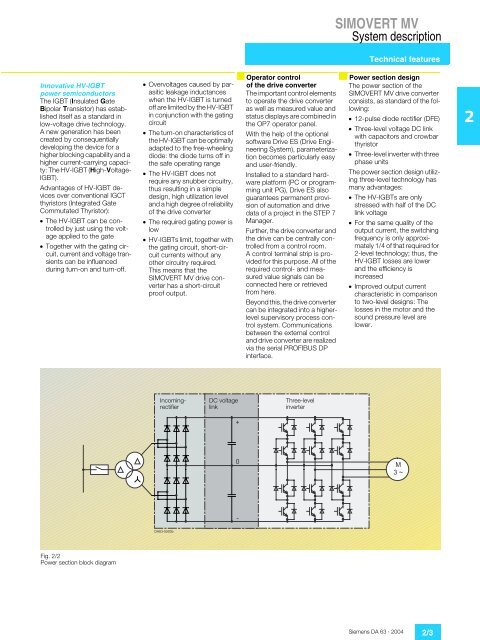
<strong>SIMOVERT</strong> <strong>MV</strong>System descriptionTechnical featuresInnovative HV-IGBTpower semiconduc<strong>to</strong>rsThe IGBT (Insulated GateBipolar Transis<strong>to</strong>r) has establisheditself as a standard inlow-voltage drive technology.A new generation has beencreated by consequentiallydeveloping the device for ahigher blocking capability and ahigher current-carrying capacity:The HV-IGBT (High-<strong>Voltage</strong>-IGBT).Advantages of HV-IGBT devicesover conventional IGCTthyris<strong>to</strong>rs (Integrated GateCommutated Thyris<strong>to</strong>r):¦ The HV-IGBT can be controlledby just using the voltageapplied <strong>to</strong> the gate¦ Together with the gating circuit,current and voltage transientscan be influencedduring turn-on and turn-off.¦ Overvoltages caused by parasiticleakage inductanceswhen the HV-IGBT is turnedoff are limited by the HV-IGBTin conjunction with the gatingcircuit¦ The turn-on characteristics ofthe HV-IGBT can be optimallyadapted <strong>to</strong> the free-wheelingdiode: the diode turns off inthe safe operating range¦ The HV-IGBT does notrequire any snubber circuitry,thus resulting in a simpledesign, high utilization leveland a high degree of reliabilityof the drive converter¦ The required gating power islow¦ HV-IGBTs limit, <strong>to</strong>gether withthe gating circuit, short-circuitcurrents without anyother circuitry required.This means that the<strong>SIMOVERT</strong> <strong>MV</strong> drive converterhas a short-circuitproof output.Opera<strong>to</strong>r controlof the drive converterThe important control elements<strong>to</strong> operate the drive converteras well as measured value andstatus displays are combined inthe OP7 opera<strong>to</strong>r panel.With the help of the optionalsoftware Drive ES (Drive EngineeringSystem), parameterizationbecomes particularly easyand user-friendly.Installed <strong>to</strong> a standard hardwareplatform (PC or programmingunit PG), Drive ES alsoguarantees permanent provisionof au<strong>to</strong>mation and drivedata of a project in the STEP 7Manager.Further, the drive converter andthe drive can be centrally controlledfrom a control room.A control terminal strip is providedfor this purpose. All of therequired control- and measuredvalue signals can beconnected here or retrievedfrom here.Beyond this, the drive convertercan be integrated in<strong>to</strong> a higherlevelsupervisory process controlsystem. Communicationsbetween the external controland drive converter are realizedvia the serial PROFIBUS DPinterface.Power section designThe power section of the<strong>SIMOVERT</strong> <strong>MV</strong> drive converterconsists, as standard of the following:¦ 12-pulse diode rectifier (DFE)¦ Three-level voltage DC linkwith capaci<strong>to</strong>rs and crowbarthyris<strong>to</strong>r¦ Three-level inverter with threephase unitsThe power section design utilizingthree-level technology hasmany advantages:¦ The HV-IGBTs are onlystressed with half of the DClink voltage¦ For the same quality of theoutput current, the switchingfrequency is only approximately1/4 of that required for2-level technology; thus, theHV-IGBT losses are lowerand the efficiency isincreased¦ Improved output currentcharacteristic in comparison<strong>to</strong> two-level designs: Thelosses in the mo<strong>to</strong>r and thesound pressure level arelower.2IncomingrectifierDC voltagelinkThree-levelinverterFig. 2/2Power section block diagramSiemens DA 63 · 2004 2/3