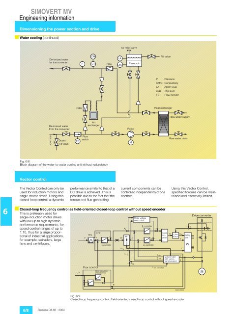
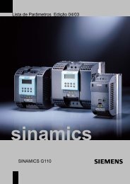
)<strong>SIMOVERT</strong> <strong>MV</strong>Engineering informationDimensioning the power section and driveWater cooling (continued)) EHHA EA BL = L A, A E E A @ M = JA HB HJD A ? L A HJA H+ 2 + 6 EJA H ) 5 ,4 A I A HL EH EL = L A2+ + ) 5 , 52 HA I I K HA+ @ K ? JEL EJO) = H A L A 6 HEF A L A M EJ H EJA H0 A = JA N ? D = C A H4 = M M = JA HI K F F O, A E E A @ M = JA HBH JD A ? L A HJA H1 A N ? D = C A H2 K F, ) $ ! # & %, H= E EL = L A 5 MI M EJ? D4 = M M = JA H@ H= EFig. 6/6Block diagram of the water-<strong>to</strong>-water cooling unit without redundancyVec<strong>to</strong>r controlThe Vec<strong>to</strong>r Control can only beused for induction mo<strong>to</strong>rs andsingle-mo<strong>to</strong>r drives. Using thisclosed-loop control, a dynamicperformance similar <strong>to</strong> that of aDC drive is achieved. This ispossible due <strong>to</strong> the fact that the<strong>to</strong>rque and flux-generatingcurrent components can becontrolled independently of oneanother.Using this Vec<strong>to</strong>r Control,specified <strong>to</strong>rques can be maintainedand effectively limited.6Closed-loop frequency control as field-oriented closed-loop control without speed encoderThis is preferably used forsingle-induction mo<strong>to</strong>r driveswith low up <strong>to</strong> high dynamicperformance requirements, forspeed control ranges of up <strong>to</strong>1:10, thus for a large proportionalof industrial applications,for example, extruders, largefans and centrifuges.n*RFGdn/dt+ + + M*n controllerMo<strong>to</strong>r voltagepre-control, m controller, m * + +M*,* w,* wYf < f sf > f s+––+ +, w controllerCoord.converterV* Vd correctionV Stawith vec<strong>to</strong>rtransformationf, w act., m act.Mo<strong>to</strong>r modelV,+ +GatingunitDrive converter+ f slipn act. calculatedY *Flux controlMo<strong>to</strong>r saturationcharacteristicsYVFig. 6/7Closed-loop frequency control: Field-oriented closed-loop control without speed encoder6/8 Siemens DA 63 · 2004
<strong>SIMOVERT</strong> <strong>MV</strong>Engineering informationVec<strong>to</strong>r controlClosed-loop speed control as field-oriented closed-loop control with speed encoderUsed for single-induction mo<strong>to</strong>rdrives and high dynamic performancerequirements even atlow speeds and increasedspeed accuracy, e.g. positioningdrives and drives for continuousmaterial webs.For this closed-loop speedcontrol, a pulse encoder, e.g.incremental encoder with 1024pulses/revolution or higher, isrequired. A DC tachometer isnot adequate due <strong>to</strong> the accuracyrequirements.Y *n*RFGdn/dt+Flux control++n controllerMo<strong>to</strong>r saturationcharacteristicsMo<strong>to</strong>r voltagepre-control, m controller, m * + +–Coord.V* Vd correctionV StconverterM*M* I* w+ +a,* w–, w controllerYf < f sf > f s++f slipf, w act.Mo<strong>to</strong>r model V, m act. with vec<strong>to</strong>rtransformation,n act.+ +GatingunitDrive converterYVFig. 6/8Closed-loop speed control: Field-oriented closed-loop control with speed encoderClosed-loop <strong>to</strong>rque control as field-orientedcontrol with speed encoderFor single-induction mo<strong>to</strong>rdrives for applications with highdynamic performance requirements,if for technical reasonsa <strong>to</strong>rque setpoint has <strong>to</strong> beentered, e.g. winder drives andslave drives with closed-looptension control.An incremental encoder is alsorequired for this control concept,with preferably 1024pulses/revolution or higher. ADC tachometer is not adequatedue <strong>to</strong> the accuracy requirements.Closed-loop control with or without speed encoderIn specific applications it is¦ closed-loop <strong>to</strong>rque control inoften unclear whether a speed a control range > 1:10encoder is needed or not.¦ a defined or changing <strong>to</strong>rqueA speed encoder is required if must be maintained forthe following criteria apply: speeds below approx. 10%¦ highest speed accuracy of the rated mo<strong>to</strong>r speed.¦ highest requirements on thedynamic performanceTerminal stripsNote:Information on the terminal stripassignment correspond <strong>to</strong> thedata which applied when thiscatalog went <strong>to</strong> print. The actualassignments should be takenfrom the circuit diagrams providedwith the drive converter.Auxiliary power supplyThe 400 V, 50 Hz auxiliary grid,which feeds the internal powersupply GSV, the control electronics,the DC link pre-chargeand the fans or cooling system,is connected via the –X5 terminalstrip. The auxiliary powersupply must have a loadable Nconduc<strong>to</strong>r since some of theloads have a single-phaseconnection.Rated auxiliary currentat 3/AC/N/400V(see drive converter selectiontables)The user is responsible that theauxiliary power supply will beinstalled and connected-upaccording <strong>to</strong> the recognizedregulations in that particularcountry as well as other regionallyvalid regulations. Cable dimensioningand fusing shouldbe particularly observed.Cross-sectionMo<strong>to</strong>r circuit-breakers can onlybe used instead of LVHC fuses(NH) if the maximum short-circuitcurrent of the supply systemdoes not exceed 6 kA.Recommended fusegL NHControl connectionVDEAWGTypeAmm 2A10-14 4 10 25 3NA381020 10 6 35 3NA381438 16 4 63 3NA3822Note:The connection cross-sections are determined for copper cables at 40 °C (104 °F) ambient temperature.Fuses of the type gL only provide reliable protection <strong>to</strong> the cables.Option Y75 allows connectingan auxiliary voltage other than400 V, 50 Hz or a power supplywithout loadable N conduc<strong>to</strong>r(IT line supply) <strong>to</strong> the -X860terminal strip.6Siemens DA 63 · 2004 6/9