SIMOVERT MV Medium-Voltage Drives 660 kVA to 9100 ... - Industry
SIMOVERT MV Medium-Voltage Drives 660 kVA to 9100 ... - Industry
SIMOVERT MV Medium-Voltage Drives 660 kVA to 9100 ... - Industry

You also want an ePaper? Increase the reach of your titles
YUMPU automatically turns print PDFs into web optimized ePapers that Google loves.
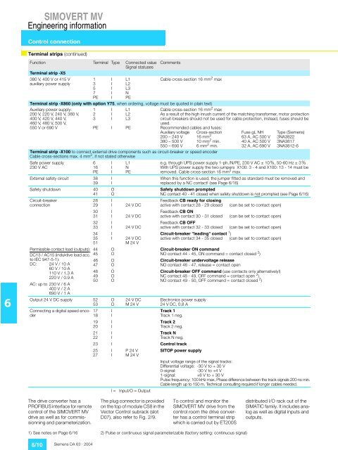
<strong>SIMOVERT</strong> <strong>MV</strong>Engineering informationControl connectionTerminal strips (continued)6Function Terminal Type Connected valueSignal statusesTerminal strip -X5380 V, 400 V or 415 Vauxiliary power supply1357PEIIIIIL1L2L3NPECommentsCable cross-section 16 mm 2 maxTerminal strip -X860 (only with option Y75, when ordering, voltage must be quoted in plain text)Auxiliary power supply:200 V, 220 V, 240 V, 380 V,400 V, 420 V, 440 V,460 V, 480 V, 500 V,550 V or 690 V123PEIIIIL1L2L3PECable cross-section 16 mm 2 maxAs a result of the high inrush current of the matching transformer, mo<strong>to</strong>r protectioncircuit-breakers should not be used for cable protection, instead, fuses should beused.Recommended cables and fuses:Auxiliary voltage Cross-section Fuse gL NH Type (Siemens)200 – 240 V 16 mm 2 63 A, AC 500 V 3NA3822380 – 500 V 10 mm 2 min. 40 A, AC 500 V 3NA3817550 – 690 V 6 mm 2 min. 32 A, AC 690 V 3NA3812-6Terminal strip -X100 <strong>to</strong> connect external drive components such as circuit-breaker or speed encoderCable cross-sections max. 4 mm 2 , if not stated otherwiseSafe power supply230 V AC616PEExternal safety circuit 3839Safety shutdown 4041Circuit-breakerconnectionPermissible contact load (outputs):DC13 / AC15 (induktive load acc.<strong>to</strong> IEC 947-5-1):DC:24 V / 10 A60 V / 10 A110 V / 1.3 A220 V / 0.9 AAC: up <strong>to</strong> 230 V / 6 A400 V / 2 A690 V / 1 A28293031323334355144454647484950Output 24 V DC supply 5253Connecting a digital speed encoder171819202122IIIIIOOIIIIIIIIOOOOOOOOOIIIIIIL1NPE24 V DC24 V DC24 V DC24 V DCM 24 V24 V DCM 24 Ve.g. through UPS power supply 1-ph./N/PE, 230 V AC ± 10%, 50-60 Hz ± 3%With UPS power supply the two jumpers X100: 3 - 4 and X100: 13 - 14 must beremoved. Cable cross-section 16 mm 2 max.When this function is used, the jumper fitted as standard must be removed andreplaced by a NC contact! (see Page 6/16)Safety shutdown promptedNC contact 40 - 41 closed when safety shutdown is not prompted (see Page 6/16)Feedback CB ready for closingactive with contact 28 - 29 closedFeedback CB ONactive with contact 30 - 31 closedFeedback CB OFFactive with contact 32 - 33 closed(can be set <strong>to</strong> contact open)(can be set <strong>to</strong> contact open)(can be set <strong>to</strong> contact open)Circuit-breaker "leading" contact 1 )active with contact 34 - 35 closed (can be set <strong>to</strong> contact open)Circuit-breaker ON commandNO contact 44 - 45, ON command = contact closed 2 )Circuit-breaker undervoltage releaseNO contact 46 - 47, release = contact openCircuit-breaker OFF command (use contacts only alternatively!)NC contact 48 - 49, OFF command = contact open 2 )NO contact 49 - 50, OFF command = contact closed 2 )Electronics power supply24 V DC, 0,8 ATrack 1Track 1 neg.Track 2Track 2 neg.Track NTrack N neg.23 I Control track2527III =P 24 VM 24 VInput/O = OutputSITOP power supplyInput voltage range of the signal tracks:Differential voltage: -30 V <strong>to</strong> + 30 V0-signal: -30 V <strong>to</strong> +4 V1-signal: +8 V <strong>to</strong> + 30 VPulse frequency: 100 kHz max, Phase difference between the track signals 200 ns min.Cable length up <strong>to</strong> 150 m. Technical consulting required if longer cables needed.The drive converter has aPROFIBUS interface for remotecontrol of the <strong>SIMOVERT</strong> <strong>MV</strong>drive as well as for commissionningand parameterization.The plug connec<strong>to</strong>r is providedon the <strong>to</strong>p of module CS8 in theVec<strong>to</strong>r Control subrack (slotD07), also refer <strong>to</strong> Fig. 2/9.To control and moni<strong>to</strong>r the<strong>SIMOVERT</strong> <strong>MV</strong> drive from thecontrol room the drive converterhas a control terminal stripwhich is carried out by ET200Sdistributed I/O rack out of theSIMATIC family. It includes analogas well as digital inputs andoutputs.1) See notes on Page 6/16 2) Pulse or continuous signal parameterizable (fac<strong>to</strong>ry setting: continuous signal)6/10 Siemens DA 63 · 2004