Create successful ePaper yourself
Turn your PDF publications into a flip-book with our unique Google optimized e-Paper software.
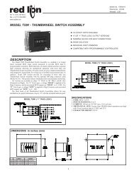
Tel +1 (717) 767-6511Fax +1 (717) 764-0839www.redlion.netDITAK 9 - ADJUSTABLE TIMEBASE 5-DIGIT RATE INDICATORBulletin No. <strong>DT9</strong>-CDrawing No. LP0534Released 4/07• DESIGNED FOR MEDIUM/HIGH SPEED APPLICATIONS• LCD, POSITIVE REFLECTIVE OR NEGATIVE TRANSMISSIVEWITH YELLOW/GREEN OR RED BACKLIGHTING• 0.46 INCH (11.68 mm) HIGH DIGITS• ADJUSTABLE TIMEBASE FROM 1 TO 7 SECONDS• RATE MULTIPLIER FROM 0.0001 TO 1.9999• SELECTABLE DECIMAL POINTS• LITHIUM BATTERY PROVIDES OVER 7 YEARS OFCONTINUOUS OPERATION (Battery included)• NEMA 4X/IP65 SEALED FRONT PANEL BEZEL• ACCEPTS MAGNETIC OR LOGIC TYPE SIGNAL INPUTSDESCRIPTIONThe DITAK 9 is a self-powered rate indicator designed to operate inmedium/high speed applications. It is ideal for use with magnetic pick-ups orother bi-polar sensors operating at a minimum of 30 Hz*. The unit featuresselectable timebase, rate multiplier, and decimal points via two front panelpushbuttons. It has a 5-digit LCD Display with 0.46" high digits that are availablein positive image reflective (black digits, reflective background) or negativeimage transmissive red or yellow/green (illuminated digits, dark background).Backlight version units require power from an external 9 to 28 VDC supply.The unit is constructed of a lightweight, high impact plastic case with a clearviewing window. The sealed front panel meets NEMA 4X/IP65 specificationsfor wash-down and/or dusty environments, when properly installed. A Ditak 9unit can be mounted in the same panel cut-out as the earlier Ditak 7 units.The optional Micro Line/Sensor Power Supply (MLPS1000) is designed toattach to the rear of an installed backlight version Ditak 9. The optional supplycan be powered from an 85 to 250 VAC source, and can provide power for thebacklighting of a unit and a sensor. The maximum current draw for the sensoris 45 mA.* - For slow speed applications with low pulse rates, it is recommended to usethe CUB5 Counter/Rate Indicator.SAFETY SUMMARYAll safety related regulations, local codes and instructions that appear in themanual or on equipment must be observed to ensure personal safety and toprevent damage to either the instrument or equipment connected to it. Ifequipment is used in a manner not specified by the manufacturer, the protectionprovided by the equipment may be impaired.CAUTION: Risk of Danger.Read complete instructions prior toinstallation and operation of the unit.SPECIFICATIONS1. DISPLAY: 5-Digit LCD, 0.46" (11.68 mm) high digits.2. POWER SOURCE: Internal 3.0 V lithium battery provides over 7 years ofcontinuous service (battery life is dependent upon usage).3. BACKLIGHT POWER REQUIREMENTS: 9 to 28 VDC @ 35 mA.Above 26 VDC, derate operating temperature to 50°C.Must use the MLPS or a Class 2 or SELV rated power supply.4. SIGNAL INPUT: 0 to 10 KHz from a magnetic or bi-polar output (with a50% duty cycle). Min. input sensitivity is 0.9 V. Max. input = 28 V.5. TIMEBASE: Adjustable in 1 sec increments via front panel. Timebaseranges from 1 second to 7 seconds; 0.05% accuracy.6. CONSTRUCTION: High impact plastic case with clear viewing window(Panel gasket and mounting clip included). Installation Category I, PollutionDegree 2.7. CERTIFICATIONS AND COMPLIANCES:SAFETYIEC 1010-1, EN 61010-1: Safety requirements for electrical equipment formeasurement, control, and laboratory use, Part 1.IP65 Enclosure rating (Face only), IEC 529Type 4X Enclosure rating (Face only), UL50ELECTROMAGNETIC COMPATIBILITYEmissions and Immunity to EN 61326Electrostatic discharge EN 61000-4-2 Criterion A4 kV contact discharge8 kV air dischargeElectromagnetic RF fields EN 61000-4-3 Criterion A10 V/mFast transients (burst)EN 61000-4-4 Criterion A2 kV power2 kV signalSurgeEN 61000-4-5 Criterion A2 kV power1 kV signalRF conducted interference EN 61000-4-6 Criterion A10 V/rmsDIMENSIONS In inches (mm)Note: Recommended minimum clearance (behind the panel) formounting clip installation is 2.15" (54.6) H x 3.00" (76.2) W.1
SPECIFICATIONS (Cont’d)Power Frequency magnetic fieldsVoltage dip/interruptionsEmissionsEN 61000-4-8 Criterion A30 A/mEN 61000-4-11 Criterion A0.5 cycleEN 55022 Class BNotes:1. Criterion A: Normal operation within specified limits.Refer to the EMC Installation Guidelines section of this bulletin foradditional information.8. ENVIRONMENTAL CONDITIONS:Operating Temperature: 0 to 75°C (Above 50°C derate backlightoperating voltage to 26 VDC max.)Storage Temperature: -30 to 80°COperating and Storage Humidity: 85% max. relative humidity (noncondensing)from 0°C to 75°C.Altitude: Up to 2000 meters9. WEIGHT: 3.3 oz (93.5 g)EMC INSTALLATION GUIDELINESAlthough this unit is designed with a high degree of immunity toElectroMagnetic Interference (EMI), proper installation and wiring methodsmust be followed to ensure compatibility in each application. The type of theelectrical noise, source or coupling method into the unit may be different forvarious installations. In extremely high EMI environments, additional measuresmay be needed. Cable length, routing and shield termination are very importantand can mean the difference between a successful or a troublesome installation.Listed below are some EMC guidelines for successful installation in anindustrial environment.1. Use shielded (screened) cables for all Signal and Control inputs. The shield(screen) pigtail connection should be made as short as possible. Theconnection point for the shield depends somewhat upon the application.Listed below are the recommended methods of connecting the shield, in orderof their effectiveness.a. Connect the shield only at the panel where the unit is mounted to earthground (protective earth).b. Connect the shield to earth ground at both ends of the cable, usually whenthe noise source frequency is above 1 MHz.c. Connect the shield to common of the unit and leave the other end of theshield unconnected and insulated from earth ground.2. Never run Signal or Control cables in the same conduit or raceway with ACpower lines, conductors feeding motors, solenoids, SCR controls, andheaters, etc. The cables should be run in metal conduit that is properlyWIRING CONNECTIONSThe electrical connections are made via rear screw-clamp terminals locatedon the back of the unit. All conductors should meet voltage and current ratingsfor each terminal. Also cabling should conform to appropriate standards of goodinstallation, local codes and regulations. It is recommended that power suppliedto the unit (AC or DC) be protected by a fuse or circuit breaker. When wiringthe unit, use the label to identify the wire position with the proper function.Strip the wire, leaving approximately 1/4" bare wire exposed (stranded wiresshould be tinned with solder). Insert the wire into the screw-clamp terminal andtighten the screw until the wire is clamped tightly. Each terminal can accept upto two #14 AWG wires.The backlighting for a backlight version unit is powered between the V+Terminal and the Common Terminal.BLOCK DIAGRAMgrounded. This is especially useful in applications where cable runs are longand portable two-way radios are used in close proximity or if the installationis near a commercial radio transmitter.3. Signal or Control cables within an enclosure should be routed as far away aspossible from contactors, control relays, transformers, and other noisycomponents.4. In extremely high EMI environments, the use of external EMI suppressiondevices, such as ferrite suppression cores, is effective. Install them on Signaland Control cables as close to the unit as possible. Loop the cable through thecore several times or use multiple cores on each cable for additional protection.Install line filters on the power input cable to the unit to suppress power lineinterference. Install them near the power entry point of the enclosure. Thefollowing EMI suppression devices (or equivalent) are recommended:Ferrite Suppression Cores for signal and control cables:Fair-Rite # 0443167251 (RLC #FCOR0000)TDK # ZCAT3035-1330ASteward #28B2029-0A0Line Filters for input power cables:Schaffner # FN610-1/07 (RLC #LFIL0000)Schaffner # FN670-1.8/07Corcom #1VR3Note: Reference manufacturer’s instructions when installing a line filter.5. Long cable runs are more susceptible to EMI pickup than short cable runs.Therefore, keep cable runs as short as possible.Variable Frequency AC Inputs, Signal Source PoweredVariable Frequency AC Inputs, Signal Source PoweredMinimum V AC for operation is 0.9 V peak.Logic Pulse Inputs From Other Circuits & Sensors2
INSTALLATION ENVIRONMENTThe unit should be installed in a location that does not exceed the maximumoperating temperature and provides good air circulation. Placing the unit neardevices that generate excessive heat should be avoided.The bezel should be cleaned only with a soft cloth and neutral soap product.Do NOT use solvents. Continuous exposure to direct sunlight may acceleratethe aging process of the bezel.INSTALLATIONThe Ditak 9 meets NEMA 4X/IP65 requirements for indoor use, whenproperly installed. The units are intended to be mounted into an enclosedpanel. A sponge rubber gasket, mounting clip, two screws, and nut fastenersare provided to install and seal the unit in the panel cut-out.The following procedure assures proper installation:1. Cut panel opening to specified dimensions. Remove burrs and clean panelopening.2. Slide the panel gasket over the rear of the unit to the back of the bezel.3. Slide nut fastener into slot on mounting clip and then insert mounting screwthrough nut on both sides of mounting clip. Tip of mounting screw shouldNOT project through hole on clip.4. Install Ditak unit through panel cut-out.5. Slide mounting clip over rear of unit until clip is against back of panel. Themounting clip and Ditak housing have a latching feature to hold the unit inplace until tightened.Note: Hold the Ditak front bezel in place when sliding the mounting clipinto position.6. Alternately tighten each mounting screw to ensure uniform gasket pressure.Visually inspect the gasket for proper seal. The gasket should becompressed approximately 75 to 80% of its original thickness.7. If the gasket is not adequately compressed and the mounting screws cannotbe tightened any further, loosen mounting screws and insure that the clip islatched as close as possible to the panel.8. Repeat step #6 for tightening the mounting screws.PROGRAMMING MENUNote: The display changes on “PAR” or “SEL” push button release.PROGRAMMINGFrom the factory, the Ditak 9 is programmed with a fixed 1 second timebaseto read directly in HZ or RPM with a 60 tooth gear To enter the programmingmode, place a jumper between the Push Button Enable (P. B. En.) Terminal andthe Common Terminal. Once the jumper is connected the programming buttonsare now activated. The Programming Mode consists of three selections; RateMultiplier, Decimal Point, and Timebase. There is a fourth display which is themain display or run mode. Once programming is complete, the unit must bereturned to the main display before exiting the programming mode to obtainnormal operation.RATE MULTIPLIERThe Ditak 9 has a Rate Multiplier (RM) selection range from 0.0001 to1.9999. See Programming Calculations to determine the calculated value. Afterentering the programming mode, the least significant digit will be flashing. Toincrement this digit, press the SEL button. After the value 9, the digit will startover at 0. To move to the next digit press PAR and then that digit can be changedby pressing SEL. When reaching the most significant digit, pressing PAR willadvance the meter to the Decimal Point selection.DECIMAL POINT SELECTIONThe selection of the decimal point position for the display (DDP) isaccomplished by repeatedly pressing SEL. This selection will always default to0.0000 when advancing to it from the Rate Multiplier selection. By pressingPAR, the shown decimal point selection is entered and the Time base selectionis shown.TIMEBASE SELECTIONThe Ditak 9 has a Time Base selection range from 1 second to 7 seconds. SeeProgramming Calculations to determine the calculated Rounded Time Base(RTB) value. The value is changed by pressing SEL. The value is entered bypressing PAR and the Main Display/Run Mode is shown.Note: The position of the decimal point has no effect on this selection.MAIN DISPLAY/RUN MODEThis display follows the Timebase Selection. The unit must be in this mode toexit the Programming Mode and have the unit display properly. The push buttonenable jumper can be removed after the Ditak 9 is returned to the main display.3
PROGRAMMING CALCULATIONS (Select one of the following)USING KNOWN RPMAn amusement park director wants his parking tram operators to keep theirspeed under a certain limit. He has a magnetic sensor looking at a shaft on thetram with 30 pulses per revolution. When the shaft is turning at 50 RPM hewants the meter to show 15.5. The Ditak 9 is programmed as follows:DR = Desired ReadingDDP = Display Decimal PointRPM = Revolutions Per MinutePPR = Pulses Per RevolutionDDP: Use the following corresponding numbers in the formula for the DisplayDecimal Point:0 = 10.0 = 100.00 = 1000.000 = 1000RPM = 50PPR = 30DR = 15.5DDP = 10HERTZ (HZ) = RPM x PPR = 50 x 30 = 2560 60CALCULATED TIME BASE = DR x DDP = 15.5 x 10 = 6.2HZ 25ROUNDED TIME BASE (RTB) = 6REMAINDER MULTIPLIER (RM) = DR x DDP = 15.5 x 10 = 1.0333RTB x HZ 6 x 25RM = 1.0333Decimal = 0.0RTB = 6ROUNDED TIME BASE (RTB) = Round Calculated Time Base to nearestwhole number between 1-7.If RM is greater than 1.9999, then remove a decimal location or add morepulses per revolution.USING KNOWN PULSES PER UNITA newspaper company wants to know the line speed of their press to tenthsof feet per minute. They have an encoder that gives 125 pulses per foot. TheDitak 9 is programmed as follows:TF = Time FactorDDP = Display Decimal PointPPU = Pulses Per (Single) UnitTF: = Use one of the following numbers in the formula for the Time Factor:Per second = 1Per minute = 60Per hour = 3600DDP: Use the following corresponding numbers in the formula for the DisplayDecimal Point:0 = 10.0 = 100.00 = 1000.000 = 1000Required minimum pulses per (single) unit:Per second = 0.07Per minute = 4.4Per hour = 259.0⎫⎬⎭(multiply this value by DDP)PPU = 125 (pulses per foot)DDP = 10 (for tenths of a foot)TF = 60 (for per minute)CALCULATED TIME BASE = TF x DDP = 60 x 10 = 4.8PPU 125ROUNDED TIME BASE (RTB)= 5REMAINDER MULTIPLIER (RM) = TF x DDP = 60 x 10 = 0.9600RTB x PPU 5 x 125RM = 0.9600Decimal = 0.0RTB = 5ROUNDED TIME BASE (RTB)= Round Calculated Time Base to nearestwhole number between 1-7.If RM is greater than 1.9999, then remove a decimal location or add morepulses per unit.ORDERING INFORMATIONMODEL NO. DESCRIPTION PART NUMBER<strong>DT9</strong>MLPSAdjustable Timebase TachometerAdjustable Timebase Tachometerwith Yellow/Green BacklightingAdjustable Timebase Tachometerwith <strong>Red</strong> BacklightingMLPS Micro Line Sensor/Power Supply<strong>DT9</strong>00000<strong>DT9</strong>00010<strong>DT9</strong>00020MLPS1000For more information on Pricing, Enclosures & Panel Mount Kits refer to theRLC Catalog or contact your local RLC distributor.TROUBLESHOOTINGFor further technical assistance, contact TechnicalSupport at the appropriate company numbers listed.<strong>Red</strong> <strong>Lion</strong> <strong>Controls</strong>20 Willow Springs CircleYork PA 17406Tel +1 (717) 767-6511Fax +1 (717) 764-0839<strong>Red</strong> <strong>Lion</strong> <strong>Controls</strong> BVPrinterweg 10NL - 3821 AD AmersfoortTel +31 (0) 334 723 225Fax +31 (0) 334 893 793<strong>Red</strong> <strong>Lion</strong> <strong>Controls</strong> AP31, Kaki Bukit Road 3,#06-04/05 TechLinkSingapore 417818Tel +65 6744-6613Fax +65 6743-3360