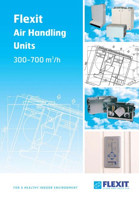
Flexit Air Handling Units - Elektra
Flexit Air Handling Units - Elektra
Flexit Air Handling Units - Elektra

Create successful ePaper yourself
Turn your PDF publications into a flip-book with our unique Google optimized e-Paper software.
NB!Our products are subject to continuous development and we therefore reserve the right tomake changes. There may also be differences between the product supplied and thecatalogue description, depending on the choice of automatic control.We disclaim liability for any printing errors that may occur.
General Technical InformationVersions<strong>Flexit</strong> air handling units are available in thefollowing versions:- horizontal unit (L). Fitted with connectionnipples at the end for installation in technicalrooms, for example.contamination in the extract air will always betransferred so that it is necessary to be selectivewhen using this recovery technology.The temperature efficiency is approximately75-85%.Outdoor airSealing strip- cabinet unit (S). Fitted with connection nippleson the top for installation in small technicalrooms, for example.The units meet the requirements in EU Directives89/336/EEC and 73/23/EEC.Exhaust airCleaning sectorExtract airSupply airUnit type LUnit type S2. Cross Exchanger(Recuperative)The cross exchanger is a cassette that consistsof a row of aluminium plates. Recovery takesplace as follows:Recovery Systems<strong>Flexit</strong> uses two different recovery technologies:1. Rotor2. Cross exchanger1. Rotor (Regenerative)<strong>Flexit</strong> uses a non-hygroscopic rotor. i.e. the rotordoes not actively emit moisture into the supplyair. This form of recovery takes place as follows:The rotor is a wheel that has a mass of aluminiumwith many ducts. This wheel rotates so thatthe mass absorbs heat from the extract air andtransfers the heat to the supply air. The rotor isdriven by a belt and a motor.Unlike the cross exchanger, the rotor technologyhas no practical problem with condensation andicing up. Therefore drainage is not required.The extract air and supply air exchange heaton separate sides of the aluminium plates. Thehot extract air heats the aluminium and thecold outdoor air then absorbs the heat. As theair flows pass on separate sides of the plates,the extract air and the supply air will neverbe in contact with each other. On accountits properties, this form of recovery involvesminimal transfer of contaminants, which, in turn,means that it can be used in a wide range ofapplications.Using a cross exchanger, moisture maybe condensed out of the extract air. Thiscondensation must be drained away.The temperature efficiency is approximately60-70%.Extract airThe internal pressure ratio in the unit is designedso that transfer of contaminants from the extractair to the supply air is minimal. The rotor has acleaning sector that functions in such a way thatthe rotor mass is “cleaned” with fresh air beforeit supplies its heat to the supply air. Some of theSupply airCross exchangerOutdoor airExhaust air4
Version 2003.12Page 125.02.2004Project dataProjectkatalogCustomer<strong>Flexit</strong>Designed byMarianneInformationLocationAssumptionsAtmospheric pressure 101325 Pa<strong>Air</strong> density 1.200 kg/m³Sound duct in accordance with ISO 5136Ambient sound in accordance with ISO 9614-2Unit specificationType of unit <strong>Flexit</strong> S 30 X E L 230DescriptionSummerWinterInputSupply air flow 500.0 l/s 500.0 l/sRelative humidity of outdoor air 50 % 10 %Total pressure drop of supply duct 250 Pa 250 PaExtract air flow 500.0 l/s 500.0 l/sRelative humidity of extract air 50 % 20 %Total pressure drop of extract duct 250 Pa 250 PaDimensioning outdoor temperature 25.0 °C -25.0 °CExtract temperature 22.0 °C 22.0 °CTechnical specificationWeight 300 kgSupplyExtractFansWinterAdjustment 0 % 0 %Power 0 W 0 WCurrent 0.00 A 0.00 APower factor 0.00 0.00SFP 0.00 kW/(m³/s) 0.00 kW/(m³/s)Temperature increase because of fan 0.0 °C 0.0 °CRPM 0 1/min 0 1/minSummerAdjustment 0 % 0 %Power 0 W 0 WCurrent 0.00 A 0.00 APower factor 0.00 0.00SFP 0.00 kW/(m³/s) 0.00 kW/(m³/s)Temperature increase because of fan 0.0 °C 0.0 °CRPM 0 1/min 0 1/minHeat recoveryTypeWinterTemperature before 0.0 °C 0.0 °CRelative humidity before 0 % 0 %Temperature after 0.0 °C 0.0 °CRelative humidity after 0 % 0 %Pressure drop 0 Pa 0 PaTemperature efficiency 0 % 0 %Humidity efficiency 0 % 0 %SummerTemperature before 0 °C 0 °CRelative humidity before 0 % 0 %Temperature after 0.0 °C 0.0 °CRelative humidity after 0 % 0 %Pressure drop 0 Pa 0 PaTemperature efficiency 0 % 0 %Humidity efficiency 0 % 0 %FilterFilter class EU7 EU7<strong>Flexit</strong> AS Telephone : +47 69 81 00 00 www.flexit.noTeleveien 15 Telefax : +47 69 81 00 80 kundeservice@flexit.no1870 ØrjeNorway94108N-032004-02Version 2003.12Page 225.02.2004All calculations are done with 20% addition at pressure drop across filters.WinterDimension pressure drop 0 Pa 0 PaStart pressure drop 0 Pa 0 PaEnd pressure drop 0 Pa 0 PaSummerDimension pressure drop 0 Pa 0 PaStart pressure drop 0 Pa 0 PaEnd pressure drop 0 Pa 0 PaElectrical afterheaterMax. effect 15.00 kWWinterEffect 0.00 kWTemperature before 0.0 °CTemperature after 0.0 °CSummerEffect 0.00 kWTemperature before 0.0 °CTemperature after 0.0 °CSound data, supplyFrequency band Hz 63 125 250 500 1k 2k 4k 8k TotalSupply duct, winter 0 0 0 0 0 0 0 0 dB 0 dB(A)Supply duct, summer 0 0 0 0 0 0 0 0 dB 0 dB(A)Sound data, extractFrequency band Hz 63 125 250 500 1k 2k 4k 8k TotalExtract duct, winter 0 0 0 0 0 0 0 0 dB 0 dB(A)Extract duct, summer 0 0 0 0 0 0 0 0 dB 0 dB(A)Sound data, ambientFrequency band Hz 63 125 250 500 1k 2k 4k 8k TotalAmbient, winter 0 0 0 0 0 0 0 0 dB 0 dB(A)Ambient, summer 0 0 0 0 0 0 0 0 dB 0 dB(A)LCC CalculationSupply air flow 0.0 l/sExtract air flow 0.0 l/sSupply air temperature 20.0 °CExtract air temperature 22.0 °CAnnual average temperature 0.0 °CCorrect coefficient VAV, supply air 0.01Correct coefficient VAV, extract air 0.01Annual operating time 4000 hPrice of energyElectric 0.000 NOK/kWhHeating 0.000 NOK/kWhAnnual price increaseElectric 3 %Heating 3 %Accounting rate of interest 3 %Operating time 10 yearsDegree hoursDegree hour for heat recovery 0 °ChCorrection for supply temperature 0 °ChCorrection due to freezing 0 °ChDegree hours, total 0 °ChLCC resultskWh NOK/kWh NOKLCC supply air 0 0.000 0LCC exhaust air 0 0.000 0LCC heating 0 0.000 0LCC total 0<strong>Flexit</strong> AS Telephone : +47 69 81 00 00 www.flexit.noTeleveien 15 Telefax : +47 69 81 00 80 kundeservice@flexit.no1870 ØrjeNorwayGeneral Technical InformationRisk of Frost Using a CrossExchangerWhen condensation is precipitated out of theextract air at low outdoor temperatures, thecondensed water will begin to freeze in theexchanger and after a while the exchanger willice up. To prevent the exchanger from icingup, <strong>Flexit</strong> has solved this problem with thedevelopment of the patented thermoguardand can guarantee operation under all climaticconditions including severe cold.InstructionsAll systems are supplied with detailedinstructions covering installation, use andmaintenance.FLEXIT S3 X/TT - A3 X/TTS4 X/TT - A4 X/TTS7 X/TT - A7 X/TTBrukerveiledningLuftbehandlingsaggregatSkapmodeller med varmegjenvinningProperties and Function ofthe ThermoguardTa vare på denne veiledningen for fremtidig brukThe thermoguard is placed inside the crossexchanger at the coldest point and monitorsboth temperature and humidity.There is a risk of frost when:1. Both humidity and cold are present2. The outdoor temperature conditions mean thatthere is a risk of dry ice in the exchanger cassette.Calculation ProgramA program for air handling unit calculations withtechnical data such as sound, air, power, SFP, etc.Deicing can be guaranteed by using a preheater.During deicing, the automatic control will reducethe air flow rate if the preheater is not able tomaintain the temperature in the cassette.Compared with traditional frost monitoringsystems (which switch off the supply air fan at +1°,regardless of whether humidity is present or not),<strong>Flexit</strong>’s solution saves a lot of energy as the unit isnot operated unnecessarily in bypass mode.Extract airOutdoor airTemperaturesensorEnvironmental ClassThe units’ chassis are produced in surfacetreatedsheet steel which meets environmentalclass M2, which covers indoor installation withnormal humidity impact and normal content ofair pollution.Cross exchangerSupply airExhaust airThermoguardCross exchanger with thermoguardEE RegulationElectrical products come under the regulationrelating to scrapped electrical and electronicproducts and are, in this connection, subject toan environmental tax. In connection with futuredisposal, they can be delivered free of chargefor recycling to the nearest dealer or collectionlocation.5
General Technical InformationExample:An air handling unit installed in a standardventilation room.<strong>Air</strong> flow rate 260m 3 /hTotal pressure100PaSound power level in supply air duct 72dBAMotor power90WExample of sound calculation using the correction tableSupply airHz 63 125 250 500 1000 2000 4000 8000Read off in diagram, LwA 72 72 72 72 72 72 72 72Correction factor 5 3 0 - 1 - 6 - 8 - 17 - 31Sound power level, Lw 77 75 72 71 66 64 55 41Data for supply air is measured in accordancewith ISO 5136, the “In-duct method”.Radiated noise is measured in accordance withISO 9614-2.Bruel & Kjær measuring equipment, type 2260.l/s 0 20 40 60 80 100 120Example of a correction axis for an F5 filter:Calculation example for F5 filter, air flow rate260m 3 /h against 100Paj .Correction for F5 filter + 30Pa, read off thecorrection axis. 260m 3 /h is available against130Pa. To read off the new sound power leveland motor power, move the read-off pointdown 30Pa to k to compensate for reducedresistance. The motor power is reduced from90W to approximately 85W, and the sound isreduced from 72dBA to 70dBA.400<strong>Air</strong> flow rate 260m 3 /hTotal pressure300Sound power level in supply air ductMotor power230V200100Pa 0190V170V150V120V105V85V60V60V130Pa70dBA77dB(A) 85W230V190V 1170V150V120V275dB(A)105V85V70dB(A)65dB(A)200150100500Wm 3 /h 0 100 200 260 300 400 500Pal/s 0 20 10 40 25608035 100 50 120 651 - 2 = 30Example of a correction axis for a water battery:Calculation example for water battery, air flowrate 260m 3 /h against 100Paj.Correction for water battery -60Pa, read off thecorrection axis. 260m 3 /h is available against40Pa. To read off the new sound power level andmotor power, move the read-off point up 60Pato k to compensate for increased resistance.The motor power is increased from 90W toapproximately 100W, and the sound is increasedfrom 72dBA to 74dBA.400<strong>Air</strong> flow rate 260m 3 /hTotal pressure300Sound power level in supply air ductMotor power230V200100Pa 0190V170V150V120V105V85V60V60V40Pa74dBA100W77dB(A)230V 2190V170V150V120V75dB(A) 1105V85V70dB(A)65dB(A)200150100500Wm 3 /h 0 100 200 260 300 400 500Pa010 25 35 50 651 - 2 = -607
General Technical InformationDetermination of Sound Pressure (LpA) from the VentilationUnit on the Basis of Sound Power (LwA)10501Diagram 1dB-5-9-1023-15-2050 100 160 200 400 800 1600romvolum (m 3 )Explanation of curvesCurve 1. Technical rooms without specialsilencing. Typically boiler rooms or refrigeratingmachine rooms with good space and hard walland ceiling surfaces.Curve 2. Typically technical rooms where thetechnical installations take up a lot of space.Partially insulated ducts/pipes or silencedsurfaces.Curve 3. Very well silenced rooms. A lot ofinstallations (not much space), insulated ducts/pipes.Table 1 Correction for distanceDistance, m 2-3 4 5 6 8 10 12 15 20Distance silencing 0 -1 -2 -3 -4 -5 -6 -7 -8Table 2 Correction for locationLocation: - in the middle of the floor 0dB- along a wall +3dB- in a corner +6dBThe curves apply to a minimum distance of1.5-2.0 m. The diagram is based on a diffusesound field. In silenced rooms (curves 2 and 3),the sound field is not diffuse. We therefore getdistance silencing. Table 1 is used to correct fordistance. Table 2 corrects for the location of theunit.8
General Technical InformationExample:An air handling unit type <strong>Flexit</strong> S4 X, installed in astandard ventilation room.<strong>Air</strong> flow rate 260m 3 /hTotal pressure100PaSound power level in supply air duct 72dBAMotor power90WThe ventilation room is 8 x 5 x 4 = 160m 3 .The unit is located along one long wall. Thereference distance is 1m.This is a technical room without special silencingand therefore we use curve 1.If we look, in diagram 1, at the room volume,160m 3 , vertically up to curve 1, and from there tothe left axis, we can read –5dB.The calculation is shown below:Sound power level (LwA), from the capacity diagram for supply air72dBCorrection for radiated sound (LwA) from the correction factor table -29,1dBCorrection for room silencing from diagram 1Correction for distance, table 1Correction for location, table 2Sound pressure level at a 1 m distance (LpA)-5dB0dB+3dB40,9dBAPS: The calculation method is based on dBAvalues. You can also use it for octave bands.The method would then produce 1-2 dB for lowvalues in the range 63-125 Hz and 1-2 dB forhigh values in the range 2000-8000 H.Explanation of name codes:S 3 X E L 230 ECS = Cabinet model/VerticalL = Loft model/HorizontalNo. = Size= Fan type= Rated voltage230V/400VL = Left modelR = Right modelE = Electrically based heatingW = Water-based heating– = No heatingX = Cross heat exchangerR = Rotating exchangerExplanation of symbols used:SUPPLYAIREXTRACTAIREXHAUSTAIROUTDOORAIR9
General Product DescriptionProduct Description<strong>Flexit</strong> air handling units are designed to provideoptimal air comfort combined with low energyconsumption. The heated, used indoor air isextracted via extraction valves from the rooms,passes through a filter and is introduced intothe unit’s cross heat exchanger before beingconducted out of the building via a roof hat orwall outlet.Outdoor air is introduced via an outdoor airintake to the unit, is filtered, passes through thecross heat exchanger and absorbs a large partof the heat from the extract air.The extract air and supply air pass each other inthe exchanger cassette in completely separateducts without the clean air being “infected” bythe used, contaminated air. The thermostatcontrolledheating battery ensures a draughtfreesupply air temperature. After the unit, thesupply air normally passes through silencersbefore flowing in through the supply air valves,fresh, clean and tempered.<strong>Flexit</strong> air handling units are fitted withelectronic automatic control.Area of Use, Horizontal <strong>Units</strong><strong>Flexit</strong> horizontal (L) air handling units aresuitable for homes for installation in the loft.These aggregates are only supplied with crossexchangers.both sides. This makes it easy to position theunits in relation to duct connections (right andleft model in one). Small building dimensionshave been the aim.Area of Use, Cabinet <strong>Units</strong>The <strong>Flexit</strong> vertical (S) cabinet version can beused to advantage for schools, nursery schools,offices, shops, homes, etc. The cabinet and thecompact design mean that the units can beused in both new and existing buildings. Theseunits are supplied with both cross exchangersand rotating exchangers.Design (S)The units are produced in sheet steel, whichresults in a robust, stable construction. Thewalls are made of double-cased galvanisedsheet steel with thermal and acousticinsulation. The connection bosses are on thetop. Externally, the units are lacquered white.All joints are sealed to eliminate the risk of airleakages. The units are fitted with two hingeddoors in the front which allow easy access forinspection/service.Design (L)<strong>Flexit</strong> air handling units are produced in strong,galvanised sheet steel, which produces a stable,robust construction. The units are double-casedwith an intermediate 50 mm of rock wool, whichproduces good thermal and acoustic insulation.All joints are sealed to eliminate the risk of airleakages. The units have inspection doors onHeat Recovery PrincipleCross ExchangerThe cross exchanger is made of aluminium. Theheat exchanger is designed with secure sealingagainst the various air chambers and can easilybe removed for cleaning and inspection. A unitwith a cross heat exchanger requires a drainagesystem for condensation water.10
General Product DescriptionSummer CassetteA summer cassette is available as an accessory.This can be used to replace the heat exchangerduring the warm part of the year.FansSingle-suction radial fans with bent-forwardblades. The fans have a high capacity, evenwith long duct sections, and have a low noiselevel. The fans are driven by a ball bearingmountedouter rotor motor of the highestquality. The motor, which is located in the fanwheel, is cooled very well. The fans can easilybe removed for cleaning (“click” electricalconnection).Rotating Heat Exchanger<strong>Flexit</strong> cabinet units can be supplied with rotatingrecovery. The rotating heat exchanger is a nonhygroscopicaluminium rotor which is mounted ina cassette. The entire cassette can be removedfrom the units for service and cleaning. The rotorwheel is mounted with maintenance-free dusttightball bearings.The rotor is driven in sequence with the heatcontrol by an electric motor via a drive belt.FiltersThe units are fitted with F7 filters on both theintake and extract air sides. The F7 filter stops97% of all particles greater than 0.5 my (1 my =1/1000 mm), i.e. pollen, dust from combustion,etc. This is a valuable property, in particularfor allergics and people with respiratory tractproblems.The filters are located in rails and are easy toreplace.HeatingIn order to ensure that the supply air has thecorrect temperature, the units are fitted withheating. This is available in the form of electricheating elements or water batteries.The water batteries are controlled by a 0-10V output which controls a 2-way or 3-way valve.11
<strong>Flexit</strong> L4 XAccessoriesSummer CassetteFilter Set L4 XArt.no.TypeArt.no.Type14206 L4 X12318 F7CI 50 Control PanelArt.no.09380CI 50 Additional boxfor surface mountingArt.no. TypeCI 500 Control PanelArt.no.09385SP450 Motion DetectorArt.no.0939009381 silver09382 whiteClosing <strong>Air</strong> Damperw/Spring ReturnArt.no. Type14482 Ø1603-way ValveArt.no. Type56597 KVS 1,6 3-wayMotor 3-way Valve230VArt.no.56596Combi. UnitArt.no. Type00797 2xØ160mm, black00798 2xØ160mm, white13
<strong>Flexit</strong> L4 XSystem Drawing, water heatingSystem Drawing, electric heatingExtract <strong>Air</strong>Outdoor <strong>Air</strong> Extract <strong>Air</strong> Outdoor <strong>Air</strong> Supply <strong>Air</strong>Exhaust <strong>Air</strong>Supply <strong>Air</strong>Exhaust <strong>Air</strong>M1 Supply air fan F10 Overheating thermostat,M2 Extract air fan manual resetFI2 Extract air filter F20 Overheating thermostatFI1 Supply air filter WB1 Water heating batteryDA1 Extract air damper EB2 Preheater(not standard) B6 ThermoguardDA2 Supply air damper B1 Supply air temperature(not standard)sensorHR-X Exchanger cassette B5 Water battery temperaturesensorM1 Supply air fan F20 Overheatn.thermostatM2 Extract air fan F21 Overheatn.thermostatFI2 Extract air filter EB1 Water heating batteryFI1 Supply air filter EB2 PreheaterHR-X Exchanger cassette B6 ThermoguardF10 Overheating thermostat B1 Supply air temperaturemanual resetsensorF11 Overheating thermostatDimensioned DrawingNB! The aggregate has 2 doors so thatit can be operated from either side.14
<strong>Flexit</strong> L4 XCapacity Diagram L4 X (measured with F7 filter)Supply air side<strong>Air</strong> flow rate, l/sl/s 0 20 40 60 80 100 120400200Contact resistance, Pa300200100Pa 0230V190V170V150V120V105V85V60V60V85V230V190V170V150V77dB(A)120V75dB(A)105V70dB(A)65dB(A)150100500WPower consumption, Wattm 3 /h 0 100 200300 400 5000 -5 -15 -30 -50 -75 Water BatteryPaAvtrekk L4x015 30 40 55 65 f5 filter<strong>Air</strong> flow rate, m 3 /hExtract air side<strong>Air</strong> flow rate, l/sl/s 0 20 40 60 80 100 120400200Contact resistance, Pa300200100Pa 0230V190V170V150V120V105V85V60V60V85V230V190V170V150V58dB(A)55dB(A)120V105V50dB(A)45dB(A)150100500WPower consumption, Wattm 3 /h 0 100 200300 400 500<strong>Air</strong> flow rate, m 3 /hSound data is given at sound power level LwA in the capacitydiagrams and is corrected with the table below for the variousoctave bands. Radiated noise produces Lw in the various octavebands and total LwA. Radiated noise is calculated by taking thenoise value from the supply air table and deducting the totalvalue from the correction factor table.Correction factor for LwHz 63 125 250 500 1000 2000 4000 8000 Total LwASupply air 3 2 -2 -5 -5 -6 -13 -29Extract air 18 14 1 -12 -14 -28 -37 -43Radiated -47 -42 -40 -43 -44 -45 -49 -57 -38,7Supply air data is measured in accordance with ISO 5136, the inductmethod. Radiated noise is measured in accordance with ISO9614-2. Bruel & Kjær measuring equipment, type 2260.Blue curves: <strong>Air</strong> capacity at various capacitysettings in Volt.Green curves: Supply air fan power consumptionat various capacity settings.Red curves: Sound power level LwA, cf.correction table.Light blue correction axe: Pressure increaseusing an EU-5 filter.Light green correction axe: Pressure increaseusing water battery.15
<strong>Flexit</strong> L7 XArt.no. Type14246 L7 XE14312 L7 XW14248 L7 XE EC14249 L7 XW ECCI 50 Control Panel included in all units(with 12 m cable).L7 XE L7 XE EC L7 XW L7 XW ECRated voltage: 230V/50Hz 230V/50Hz 230V/50Hz 230V/50HzFuse: 16 A 16 A 10 A 16 ARated current, total: 10,7 A 10,2 A 6,4 A 5,9 ARated power, total: 2 470 W 2 350 W 1 470 W 1 350 WRated power, electric battery: 2 000 W 2 000 WRated power, fans: 2 x 230 W 2 x 170 W 2 X 230 W 2 X 170 WRated preheating power: 1 000 W 1 000 W 1 000 W 1 000 WFan type: F-wheel f-wheel f-wheel f-wheelFan motor control: Transformer EC-stepless Transformer EC-steplessMax. fan speed: 2 120 rpm 2 250 rpm 2 120 rpm 2 250 rpmAutomatic, standard: CS 50 CS 50 CS 50 CS 50Filter type (SUP/EXTR): F7/G3 F7/G3 F7/G3 F7/G3Filter dimensions SUP (WxHxD): 394x223x250mm 394x223x250mm 394x223x250mm 394x223x250mmFilter dimensions EXTR (WxHxD): 394x223x20mm 394x223x20mm 394x223x20mm 394x223x20mmWeight: 66 kg 66 kg 66 kg 66 kgDuct connection: Ø 250 mm Ø 250 mm Ø 250 mm Ø 250 mmHeight: 680 mm 680 mm 680 mm 680 mmWidth: 1 170 mm 1 170 mm 1 170 mm 1 170 mmDepth: 465 mm 465 mm 465 mm 465 mm18
<strong>Flexit</strong> L7 XAccessoriesSummer CassetteFilter Set L7 XArt.no.TypeArt.no.Type14210 L7 X12313 F7CI 50 Control PanelArt.no.09380CI 50 Additional boxfor surface mountingArt.no. TypeCI 500 Control PanelArt.no.09385SP450 Motion DetectorArt.no.0939009381 silver09382 whiteLukkespjeldArt.no.Type14481 Ø200w/Spring Return14485 Ø250w/Spring Return3-way ValveArt.no. Type56597 KVS 1,6 3-wayMotor 3-way Valve230VArt.no.56596Combi. UnitArt.no. Type00797 2xØ160mm, black00798 2xØ160mm, white00799 2xØ200mm, white00800 2xØ200mm, black19
<strong>Flexit</strong> L7 XSystem Drawing, water heatingSystem Drawing, electric heatingExtract <strong>Air</strong>Outdoor <strong>Air</strong> Extract <strong>Air</strong>Outdoor <strong>Air</strong> Supply <strong>Air</strong>Exhaust <strong>Air</strong>Supply <strong>Air</strong>Exhaust <strong>Air</strong>M1 Supply air fan F10 Overheating thermostat,M2 Extract air fan manual resetFI2 Extract air filter F20 Overheating thermostatFI1 Supply air filter WB1 Water heating batteryDA1 Extract air damper EB2 Preheater(not standard) B6 ThermoguardDA2 Supply air damper B1 Supply air temperaturesensor (not standard) B5 Water battery temperatureHR-X Exchanger cassettesensorM1 Supply air fan EB1 Water heating batteryM2 Extract air fan EB2 PreheaterFI2 Extract air filter B6 ThermoguardFI1 Supply air filter B1 Supply air temperatureHR-X Exchanger cassettesensorF20 Overheatn.thermostat F10 Overheating thermostat,F21 Overheatn.thermostat manual resetF11 Overheating thermostatDimensioned DrawingNB! The aggregate has 2 doors so thatit can be operated from either side.20
<strong>Flexit</strong> L7 XCapacity Diagram L7 X (measured with F7 filter)Supply air side<strong>Air</strong> flow rate, l/sl/s 0 40 80 120 160200500250Contact resistance, Pa400300200100Pa 0230V190V170V150V120V105V85V60V60V85V230V190V170V150V120V105V80dB(A)75dB(A)65dB(A)70dB(A)200150100500WPower consumption, Wattm 3 /h 0 200 400 6008000 -5 -15 -25 -40 -55 Water BatteryPa020 35 50 65 85 f5-filter<strong>Air</strong> flow rate, m 3 /hExtract air side<strong>Air</strong> flow rate, l/sl/s 0 40 80 120 160200500250Contact resistance, Pa400300200100Pa 0230V190V170V150V120V105V85V60V60V85V120V105V150V190V170V50dB(A) 55dB(A)230V60dB(A)64dB(A)200150100500WPower consumption, Wattm 3 /h 0 200 400 600800Pa020 35 50 60<strong>Air</strong> flow rate, m 3 /hF5 FilterSound data is given at sound power level LwA in the capacitydiagrams and is corrected with the table below for the variousoctave bands. Radiated noise produces Lw in the various octavebands and total LwA. Radiated noise is calculated by taking thenoise value from the supply air table and deducting the totalvalue from the correction factor table.Correction factor for LwHz 63 125 250 500 1000 2000 4000 8000 Total LwASupply air 3 1 2 -1 -7 -11 -18 -31Extract air 10 8 5 -2 -11 -19 -30 -48Radiated -55 -43 -35 -36 -33 -31 -40 -50 -27,1Supply air data is measured in accordance with ISO 5136, the inductmethod. Radiated noise is measured in accordance with ISO9614-2. Bruel & Kjær measuring equipment, type 2260.Blue curves: <strong>Air</strong> capacity at various capacitysettings in Volt.Green curves: Supply air fan power consumptionat various capacity settings.Red curves: Sound power level LwA, cf.correction table.Light blue correction axe: Pressure increaseusing an EU-5 filter.Light green correction axe: Pressure increaseusing water battery.21
<strong>Flexit</strong> L7 X ECCapacity Diagram L7 X EC (measured with F7 filter)Supply <strong>Air</strong>sside<strong>Air</strong> flow rate, l/sl/s 0 40 80 120 160200500250Contact resistance, Pa40030020010020015010050Power consumption, WattPa00Wm 3 /h 0 200 400 6008000 -5 -15 -25 -40 -55 Water BatteryPa020 35 50 65 85 f5-filter<strong>Air</strong> flow rate, m 3 /hExtract <strong>Air</strong>sside<strong>Air</strong> flow rate, l/sl/s 0 40 80 120 160200500250Contact resistance, Pa400300200200150100Power consumption, Watt100Pa 0500Wm 3 /h 0 200 400 600800Correction factor for Lw<strong>Air</strong> flow rate, m 3 /hSound data is given at sound power level LwA in the capacitydiagrams and is corrected with the table below for the variousoctave bands. Radiated noise produces Lw in the various octavebands and total LwA. Radiated noise is calculated by taking thenoise value from the supply air table and deducting the totalvalue from the correction factor table.Hz 63 125 250 500 1000 2000 4000 8000 Total LwASupply air 6 1 -2 -4 -5 -7 -14 -27Extract air 11 2 4 0 -13 -15 -28 -44Radiated -36 -31 -33 -41 -42 -39 -41 -47 -33,4Supply air data is measured in accordance with ISO 5136, the inductmethod. Radiated noise is measured in accordance with ISO9614-2. Bruel & Kjær measuring equipment, type 2260.Blue curves: <strong>Air</strong> capacity at various capacitysettings in Volt.Green curves: Supply air fan power consumptionat various capacity settings.Red curves: Sound power level LwA, cf.correction table.Light blue correction axe: Pressure increaseusing an EU-5 filter.Light green correction axe: Pressure increaseusing water battery.22
<strong>Flexit</strong> S3 RArt.no. Type14010 S3 REL14011 S3 RERCI 50 Control Panel included in all units(with 12 m cable).S3 RRated voltage:230V/50HzFuse:10ARated current, total: 5,5ARated power, total:1271WRated power, electric battery: 900WRated power, fans:2 x 165WRated preheating power: -Fan type:F-wheelFan motor control:TransformerMax. fan speed:2230rpmAutomatic, standard: CS 50Filter type (SUP/EXTR):F7/F7Filter dimensions SUP (WxHxD): 285x130x50mmFilter dimensions EXTR (WxHxD): 285x130x50mmWeight:38,5 kg (without kitchen hood)Duct connection:Ø125mm (127mm female)Height:700mm (without kitchen hood)Width:598mmDepth:320mm24
<strong>Flexit</strong> S3 RAccessoriesFilter SetCI 50 Control PanelCI 50 Additional boxCI 500 Control PanelArt.no.12328Art.no.09380for for surface mountingArt.no. Type09381 silverArt.no.0938509382 whiteSP 450 Motion DetectorCombi. UnitArt.no.Art.no.Type0939000801 2xØ125mm, white00802 2xØ125mm, black00797 2xØ160mm, black00798 2xØ160mm, whiteFor external installation with S3 R mod.:Brasserie-E, whiteArt.no. 13750Brasserie-E, steelArt.no. 13751Fondue-EArt.no. 13616Bistro-EArt.no. 13626Frontlist, steelArt.no. 1366325
<strong>Flexit</strong> S3 RSystem DrawingFI2M1B1EB1F10F20FI1M2B1 Supply air temperature sensorEB1 Water heating batteryF10 Overheating thermostat,manual resetF20 Overheating thermostat,automatisk resetFI1 Supply air filterFI2 Extract air filterM1 Supply <strong>Air</strong>fanM2 Extract air fanHR-R Rotating heat exchangerM4 Rotor motorHR-RM4Dimensioned Drawing (right model)Dimensions in mmDuct connection (right model)kitchenhood26
<strong>Flexit</strong> S3 RCapacity Diagram S3 R (measured with F7 filter)Supply air side<strong>Air</strong> flow rate, l/s Contact resistance, Pa Power consumption, Watt <strong>Air</strong> flow rate, m 3 /hExtract air side<strong>Air</strong> flow rate, l/s Contact resistance, Pa Power consumption, Watt <strong>Air</strong> flow rate, m 3 /hSound data is given at sound power level LwA in the capacitydiagrams and is corrected with the table below for the variousoctave bands. Radiated noise produces Lw in the various octavebands and total LwA. Radiated noise is calculated by taking thenoise value from the supply air table and deducting the totalvalue from the correction factor table.Correction factor for LwHz 63 125 250 500 1000 2000 4000 8000 Total LwASupply air 3 2 -2 -5 -5 -6 -13 -29Extract air 18 14 1 -12 -14 -28 -37 -43Radiated -47 -42 -40 -43 -44 -45 -49 -57 -38,7Supply air data is measured in accordance with ISO 5136, the inductmethod. Radiated noise is measured in accordance with ISO9614-2. Bruel & Kjær measuring equipment, type 2260.Blue curves: <strong>Air</strong> capacity at various capacitysettings in Volt.Green curves: Supply air fan power consumptionat various capacity settings.Red curves: Sound power level LwA, cf.correction table.Light blue correction axe: Pressure increaseusing an EU-5 filter.Light green correction axe: Pressure increaseusing water battery.27
<strong>Flexit</strong> S3 RKArt.no. Type14012 S3 RKEL14013 S3 RKERCI 50 Control Panel included in all units(with 12 m cable).Kitchen hood for installation, S3 RK mod.:Art.no. Type13756 Brasserie-KL, white13754 Brasserie-KR, white13757 Brasserie-KL, steel13755 Brasserie-KR, steel55678 <strong>Air</strong> flow rate, l/s equipment, white55679 <strong>Air</strong> flow rate, l/s equipment, steelS3 RKRated voltage:230V/50HzFuse:10ARated current, total: 5,5ARated power, total:1271WRated power, electric battery: 900WRated power, fans:2 x 165WRated preheating power: -Fan type:F-wheelFan motor control:TransformerMax. fan speed:2230rpmAutomatic, standard: CS 50Filter type (SUP/EXTR):F7/F7Filter dimensions SUP (WxHxD): 285x130x50mmFilter dimensions EXTR(WxHxD): 285x130x50mmWeight:38,5 kg (without kitchen hood)Duct connection:Ø125mm (127mm female)Duct connection:Ø125mmHeight:700mm (without kitchen hood)Width:598mmDepth:320mm28
<strong>Flexit</strong> S3 RKAccessoriesFilter SetCI 50 Control PanelCI 50 Additional boxCI 500 Control PanelArt.no.12328Art.no.09380for for surface mountingArt.no. Type09381 silverArt.no.0938509382 whiteSP 450 Motion DetectorCombi. UnitArt.no.Art.no.Type0939000801 2xØ125mm, white00802 2xØ125mm, black00797 2xØ160mm, black00798 2xØ160mm, white29
<strong>Flexit</strong> S3 RKSystem DrawingFI2M1B1EB1F10F20FI1M2B1EB1F10F20FI1FI2M1M2HR-RM4KDA4Supply air temperature sensorWater heating batteryOverheating thermostat,manual resetOverheating thermostat,automatisk resetSupply air filterExtract air filterSupply <strong>Air</strong>fanExtract air fanRotating heat exchangerRotor motorKitchen hoodDamper, kitchen hoodHR-RM4DA4KDimensioned Drawing (right model)Dimensions in mmDuct connection (right model)kitchenhood 30
<strong>Flexit</strong> S3 RKCapacity Diagram S3 RK (measured with F7 filter)Supply air side<strong>Air</strong> flow rate, l/s Contact resistance, Pa Power consumption, Watt <strong>Air</strong> flow rate, m 3 /hExtract air side<strong>Air</strong> flow rate, l/s Contact resistance, Pa Power consumption, Watt <strong>Air</strong> flow rate, m 3 /hSound data is given at sound power level LwA in the capacitydiagrams and is corrected with the table below for the variousoctave bands. Radiated noise produces Lw in the various octavebands and total LwA. Radiated noise is calculated by taking thenoise value from the supply air table and deducting the totalvalue from the correction factor table.Correction factor for LwHz 63 125 250 500 1000 2000 4000 8000 Total LwASupply air 3 2 -2 -5 -5 -6 -13 -29Extract air 18 14 1 -12 -14 -28 -37 -43Radiated -47 -42 -40 -43 -44 -45 -49 -57 -38,7Supply air data is measured in accordance with ISO 5136, the inductmethod. Radiated noise is measured in accordance with ISO9614-2. Bruel & Kjær measuring equipment, type 2260.Blue curves: <strong>Air</strong> capacity at various capacitysettings in Volt.Green curves: Supply air fan power consumptionat various capacity settings.Red curves: Sound power level LwA, cf.correction table.Light blue correction axe: Pressure increaseusing an EU-5 filter.Light green correction axe: Pressure increaseusing water battery.31
<strong>Flexit</strong> S4 RArt.no. Type14160 S4 REL14161 S4 RER14162 S4 R L14163 S4 R R14164 S4 REL EC14165 S4 RER EC14166 S4 R L EC14167 S4 R R ECCI 50 Control Panel included in all units(with 12 m cable).S4 RE S4 RE EC S4 RW S4 RW ECRated voltage: 230V/50Hz 230V/50Hz 230V/50Hz 230V/50HzFuse: 10 A 10 A 10 A 10 ARated current, total: 6,8 A 6,1 A 1,6 A 0,9 ARated power, total: 1 581 W 1 417 W 381 W 217 WRated power, electric battery: 1 200 W 1 200 WRated power, fans: 2 x 165 W 2 x 83 W 2 x 165 W 2 x 83 WFan type: f-wheel f-wheel f-wheel f-wheelFan motor control: Transformer EC-stepless Transformer EC-steplessMax. fan speed: 2 230 rpm 1 970 rpm 2 230 rpm 1 970 rpmAutomatic, standard: CS 50 CS 50 CS 50 CS 50Filter type (SUP/EXTR): f7/F7 F7/F7 F7/F7 F7/F7Filter dimensions SUP (WxHxD): 468x200x70mm 468x200x70mm 468x200x70mm 468x200x70mmFilter dimensions EXTR (WxHxD): 468x200x70mm 468x200x70mm 468x200x70mm 468x200x70mmWeight: 85 kg 85 kg 85 kg 85 kgDuct connection: Ø 200 mm Ø 200 mm Ø 200 mm Ø 200 mmHeight: 900 mm 900 mm 900 mm 900 mmWidth: 900 mm 900 mm 900 mm 900 mmDepth: 550 mm 550 mm 550 mm 550 mm32
<strong>Flexit</strong> S4 RAccessoriesFilter SetArt.no.12327CI 50 Control PanelArt.no.09380CI 50 Additional boxfor surface mountingArt.no. TypeCI 500 Control PanelArt.no.0938509381 silver09382 white3-way ValveArt.no. Type56604 KVS 1,0 3-way56597 KVS 1,6 3-wayMotor 3-way Valve230VArt.no.56596Water CoilArt.no. Type14466 Ø160SP450 Motion DetectorArt.no.09390Closing <strong>Air</strong> Damperw/Spring ReturnCombi. UnitArt.no. TypeArt.no.Type00797 2xØ160mm, black14482 Ø16000798 2xØ160mm, white33
<strong>Flexit</strong> S4 RSystem Drawing, water heatingSystem Drawing, electric heating(right model)(right model)Supply <strong>Air</strong> Extract <strong>Air</strong> Exhaust <strong>Air</strong> Outdoor <strong>Air</strong>Supply <strong>Air</strong> Extract <strong>Air</strong> Exhaust <strong>Air</strong> Outdoor <strong>Air</strong>B1FI2FI1B1FI2M2FI1M2M1HR-RM4M1F10 F20EB1HR-RM4FI2 Extract air filterFI1 Supply air filterHR-R Rotating heat exchangerB1 Supply air temperaturesensorB5 Temperature sensorM1 Supply air fanM2 Extract air fanM4 Rotor motorFI2 Extract air filterFI1 Supply air filterHR-R Rotating heat exchangerB1 Supply air temperaturesensorEB1 Water heating batteryF10 Overheating thermostat,manual resetF20 Overheating thermostatM1 Supply air fanM2 Extract air fanM4 Rotor motorDimensioned Drawing (left modell) Dimensions in mm34
<strong>Flexit</strong> SL4 RArt.no. Type14020 SL4 REL14021 SL4 RER14022 SL4 R L14023 SL4 R R14024 SL4 REL EC14025 SL4 RER EC14026 SL4 R L EC14027 SL4 R R ECCI 50 Control Panel included in all units(with 12 m cable).SL4 RE SL4 RE EC SL4 RW SL4 RW ECRated voltage: 230V/50Hz 230V/50Hz 230V/50Hz 230V/50HzFuse: 10 A 10 A 10 A 10 ARated current, total: 5,5 A 4,8 A 1,6 A 0,9 ARated power, total: 1 271 W 1 107 W 371 W 207 WRated power, electric battery: 900 W 900 W - -Rated power, fans: 2 x 165 W 2 X 83 W 2 x 165 W 2 X 83 WRated preheating power:Fan type: F-wheel F-wheel F-wheel F-wheelFan motor control: Transformer EC-stepless Transformer EC-steplessMax. fan speed: 2 230 rpm 1 970 rpm 2 230 rpm 1 970 rpmAutomatic, standard: CS 50 CS 50 CS 50 CS 50Filter type (SUP/EXTR): F7/F7 F7/F7 F7/F7 F7/F7Filter dimensions SUP (WxHxDmm): 350x185x50 350x185x50 350x185x50 350x185x50Filter dimensions EXTR (WxHxDmm): 350x185x50 350x185x50 350x185x50 350x185x50Weight: 48 kg 48 kg 48 kg 48 kgDuct connection: Ø 160 mm Ø 160 mm Ø 160 mm Ø 160 mmDuct connection, kitchen hood: Ø 125 mm Ø 125 mm Ø 125 mm Ø 125 mmHeight: 700 mm 700 mm 700 mm 700 mmWidth: 598 mm 598 mm 598 mm 598 mmDepth: 455 mm 455 mm 455 mm 455 mm38
<strong>Flexit</strong> SL4 RAccessoriesFilter SetArt.no.12336CI 50 Control PanelArt.no.09380CI 50 Additional boxfor surface mountingArt.no. Type09381 silver09382 whiteCI 500 Control PanelArt.no.09385SP450 Motion DetectorArt.no.09390Closing <strong>Air</strong> Damperw/Spring ReturnArt.no. Type14482 Ø1603-way ValveArt.no. Type56597 KVS 1,6 3-wayMotor 3-way Valve230VArt.no.56596Water CoilArt.no. Type14466 Ø160Combi. UnitArt.no. Type00797 2xØ160mm, black00798 2xØ160mm, white00799 2xØ200mm, white00800 2xØ200mm, blackFor external installation with SL4 R mod.:Brasserie-E, whiteArt.no. 13750Brasserie-E, steelArt.no. 13751Fondue-EArt.no. 13616Bistro-EArt.no. 13626Frontlist, steelArt.no. 1366339
<strong>Flexit</strong> SL4 RSystem Drawing, water heatingExtract <strong>Air</strong> Supply <strong>Air</strong> Outdoor <strong>Air</strong> Exhaust <strong>Air</strong>System Drawing, electric heatingExtract <strong>Air</strong> Supply <strong>Air</strong> Outdoor <strong>Air</strong> Exhaust <strong>Air</strong>B1B1B5KB5KM1M2FI2FI2M1EB1F10F20FI1FI1M2FI2M1FI1M2HR-RHR-RM4HR-RM4M4B1B5FI1FI2M1Supply air temperaturesensorTemperature sensor,water batterySupply air filterExtract air filterSupply air fanM2 Extract air fanHR-R Rotating heatexchangerM4 Rotor motorK Kitchen hood(accessories)320455107 107598128Dimensioned Drawing107 107598Dimensions in mmØ160Ø125Ø160128700320700455107 107598Ø160Ø160Ø125Ø160Ø160Ø160299106299106700Kitchen hoodØ160299106299Ø16010640320106106320320106128B1EB1F10F20FI1Supply air temperaturesensorWater heating batteryOverhetingstermostat,manual resetOverhetingstermostat,automatic resetSupply air filter320455FI2 Extract air filterM1 Supply air fanM2 Extract air fanHR-R Rotating heatexchangerM4 Rotor motorK Kitchen hood(accessories)Ø160Ø125Shown from belowØ160Ø160299106299106106320106320106320Shown from aboveFront
<strong>Flexit</strong> SL4 RCapacity Diagram SL4 R (measured with F7 filter)Supply air side<strong>Air</strong> flow rate, l/sl/s 0 20 40 60 80 100400200Contact resistance, Pa300200100Pa 0150100 50 0WPower consumption, Wattm 3 /h 0 100 200300 400 Pa0 <strong>Air</strong> flow rate, m 3 /hExtract air side<strong>Air</strong> flow rate, l/s 0 Contact resistance, PaPa WPower consumption, Wattm 3 /h 0 100 200300 400Pa0 <strong>Air</strong> flow rate, m 3 /hSound data is given at sound power level LwA in the capacitydiagrams and is corrected with the table below for the variousoctave bands. Radiated noise produces Lw in the various octavebands and total LwA. Radiated noise is calculated by taking thenoise value from the supply air table and deducting the totalvalue from the correction factor table.Correction factor for LwHz 63 125 250 500 1000 2000 4000 8000 Total LwASupply air 3 1 2 -1 -7 -11 -18 -31Extract air 10 8 5 -2 -11 -19 -30 -48Radiated -55 -43 -35 -36 -33 -31 -40 -50 -27,1Supply air data is measured in accordance with ISO 5136, the inductmethod. Radiated noise is measured in accordance with ISO9614-2. Bruel & Kjær measuring equipment, type 2260.Blue curves: <strong>Air</strong> capacity at various capacitysettings in Volt.Green curves: Supply air fan power consumptionat various capacity settings.Red curves: Sound power level LwA, cf.correction table.Light blue correction axe: Pressure increaseusing an EU-5 filter.Light green correction axe: Pressure increaseusing water battery.41
<strong>Flexit</strong> SL4 R ECCapacity Diagram SL4 R EC (measured with F7 filter)Supply <strong>Air</strong>sside<strong>Air</strong> flow rate, l/s 0 Contact resistance, PaPower consumption, WattPa Wm 3 /h 0 100 200300 400 Pa0 <strong>Air</strong> flow rate, m 3 /hExtract <strong>Air</strong>sside<strong>Air</strong> flow rate, l/s 0 Contact resistance, PaPa WPower consumption, Wattm 3 /h 0 100 200300 400Pa0 <strong>Air</strong> flow rate, m 3 /hf5-filterSound data is given at sound power level LwA in the capacitydiagrams and is corrected with the table below for the variousoctave bands. Radiated noise produces Lw in the various octavebands and total LwA. Radiated noise is calculated by taking thenoise value from the supply air table and deducting the totalvalue from the correction factor table.Correction factor for LwHz 63 125 250 500 1000 2000 4000 8000 Total LwASupply air 9 3 -1 -2 -4 -10 -18 -31Extract air 13 9 3 -2 -10 -19 -31 -48Radiated -48 -38 -33 -34 -30 -29 -39 -50 -25,5Supply air data is measured in accordance with ISO 5136, the inductmethod. Radiated noise is measured in accordance with ISO9614-2. Bruel & Kjær measuring equipment, type 2260.Blue curves: <strong>Air</strong> capacity at various capacitysettings in Volt.Green curves: Supply air fan power consumptionat various capacity settings.Red curves: Sound power level LwA, cf.correction table.Light blue correction axe: Pressure increaseusing an EU-5 filter.Light green correction axe: Pressure increaseusing water battery.42
<strong>Flexit</strong> S7 RArt.no. Type14170 S7 REL14171 S7 RER14172 S7 R L14173 S7 R R14174 S7 REL EC14175 S7 RER EC14176 S7 R L EC14177 S7 R R ECCI 50 Control Panel included in all units(with 12 m cable).S7 RE S7 RE EC S7 RW S7 RW ECRated voltage: 230V/50Hz 230V/50Hz 230V/50Hz 230V/50HzFuse: 16 A 13 A 10 A 10 ARated current, total: 14,2 A 12,4 A 3,3 A 1,5 ARated power, total: 3 265 W 2 845 W 765 W 345 WRated power, electric battery: 2 500 W 2 500 WRated power, fans: 2 x 375 W 2 x 175 W 2 x 375 W 2 x 175 WFan type: F-wheel f-wheel f-wheel f-wheelFan motor control: Transformer EC-stepless Transformer EC-steplessMax. fan speed: 2000 rpm 2000 rpm 2000 rpm 2000 rpmAutomatic, standard: CS 50 CS 50 CS 50 CS 50Filter type (SUP/EXTR): F7/F7 F7/F7 F7/F7 F7/F7Filter dimensions SUP (WxHxD): 468x200x70mm 468x200x70mm 468x200x70mm 468x200x70mmFilter dimensions EXTR (WxHxD): 468x200x50mm 468x200x70mm 468x200x70mm 468x200x70mmWeight: 92 kg 92 kg 92 kg 92 kgDuct connection: Ø 200 mm Ø 200 mm Ø 200 mm Ø 200 mmHeight: 900 mm 900 mm 900 mm 900 mmWidth: 900 mm 900 mm 900 mm 900 mmDepth: 550 mm 550 mm 550 mm 550 mm44
<strong>Flexit</strong> S7 RAccessoriesFilter SetArt.no.12327CI 50 Control PanelArt.no.09380CI 50 Additional boxfor surface mountingArt.no. Type09381 silver09382 whiteCI 500 Control PanelArt.no.093853-way ValveArt.no. Type56604 KVS 1,0 3-way56597 KVS 1,6 3-wayMotor 3-way Valve230VArt.no.56596Water CoilArt.no. Type14467 Ø200SP450 Motion DetectorArt.no.09390Closing <strong>Air</strong> Damperw/Spring ReturnArt.no. Type14482 Ø16014481 Ø200Combi. UnitArt.no. Type00797 2xØ160mm, black00798 2xØ160mm, white00799 2xØ200mm, white00800 2xØ200mm, black45
<strong>Flexit</strong> S7 RSystem Drawing, water heating(right model)System Drawing, electric heating(right model)Supply <strong>Air</strong> Extract <strong>Air</strong> Exhaust <strong>Air</strong> Outdoor <strong>Air</strong>Supply <strong>Air</strong> Extract <strong>Air</strong> Exhaust <strong>Air</strong> Outdoor <strong>Air</strong>B1FI2FI1B1FI2M2FI1M2M1HR-RM4M1F10 F20EB1HR-RM4FI2 Extract air filterFI1 Supply air filterHR-R Rotating heatexchangerB1 Temperature sensor,supply airB5 Temperature sensorM1 Supply air fanM2 Extract air fanM4 Rotor motorFI2 Extract air filterFI1 Supply air filterHR-R Rotating heatexchangerB1 Temperature sensor,supply airEB1 Water heating batteryF10 Overheating thermostat,manual resetF20 Overheating thermostatM1 Supply air fanM2 Extract air fanM4 Rotor motorDimensioned Drawing (left modell) Dimensions in mm46
<strong>Flexit</strong> S7 RCapacity Diagram S7 R (measured with F7 filter)Supply air side<strong>Air</strong> flow rate, l/sl/s 0 40 80 120 160200350Contact resistance, Pa600400200Pa 0 75dB(A) 70dB(A)65dB(A)300250200150100500WPower consumption, Wattm 3 /h 0 600800 Pa0 <strong>Air</strong> flow rate, m 3 /hExtract air side<strong>Air</strong> flow rate, l/sl/s 0 40 80 120 160200350Contact resistance, Pa600400200Pa 0 85V 300250200150100500WPower consumption, Wattm 3 /h 0 200 400 600800PaCorrection factor for Lw0 <strong>Air</strong> flow rate, m 3 /hSound data is given at sound power level LwA in the capacitydiagrams and is corrected with the table below for the variousoctave bands. Radiated noise produces Lw in the various octavebands and total LwA. Radiated noise is calculated by taking thenoise value from the supply air table and deducting the totalvalue from the correction factor table.Hz 63 125 250 500 1000 2000 4000 8000 Total LwASupply air 3 1 -4 -4 -5 -7 -19 -24Extract air 10 11 3 -4 -9 -15 -26 -41Radiated -43 -31 -33 -34 -38 -38 -39 -44 -30,6Supply air data is measured in accordance with ISO 5136, the inductmethod. Radiated noise is measured in accordance with ISO9614-2. Bruel & Kjær measuring equipment, type 2260.Blue curves: <strong>Air</strong> capacity at various capacitysettings in Volt.Green curves: Supply air fan power consumptionat various capacity settings.Red curves: Sound power level LwA, cf.correction table.Light blue correction axe: Pressure increaseusing an EU-5 filter.Light green correction axe: Pressure increaseusing water battery.47
<strong>Flexit</strong> S7 R ECCapacity Diagram S7 R EC (measured with F7 filter)Supply <strong>Air</strong>sside<strong>Air</strong> flow rate, l/sl/s 0 40 80 120 160600Contact resistance, Pa400200Power consumption, WattPa0 0Wm 3 /h 0 200 400600 Pa0 <strong>Air</strong> flow rate, m 3 /hExtract <strong>Air</strong>sside<strong>Air</strong> flow rate, l/sl/s 0 40 80 120 160600Contact resistance, Pa400200Pa 0 0WPower consumption, Wattm 3 /h 0 200 400600Pa0 <strong>Air</strong> flow rate, m 3 /hSound data is given at sound power level LwA in the capacitydiagrams and is corrected with the table below for the variousoctave bands. Radiated noise produces Lw in the various octavebands and total LwA. Radiated noise is calculated by taking thenoise value from the supply air table and deducting the totalvalue from the correction factor table.Correction factor for LwHz 63 125 250 500 1000 2000 4000 8000 Total LwASupply air 3 1 -4 -4 -5 -7 -14 -24Extract air 10 11 -3 -4 -9 -15 -26 -41Radiated -43 -31 -33 -34 -38 -38 -39 -44 -30,6Supply air data is measured in accordance with ISO 5136, the inductmethod. Radiated noise is measured in accordance with ISO9614-2. Bruel & Kjær measuring equipment, type 2260.Blue curves: <strong>Air</strong> capacity at various capacitysettings in Volt.Green curves: Supply air fan power consumptionat various capacity settings.Red curves: Sound power level LwA, cf.correction table.Light blue correction axe: Pressure increaseusing an EU-5 filter.Light green correction axe: Pressure increaseusing water battery.48