Pool & Spa Heaters
Pool & Spa Heaters
Pool & Spa Heaters

Create successful ePaper yourself
Turn your PDF publications into a flip-book with our unique Google optimized e-Paper software.
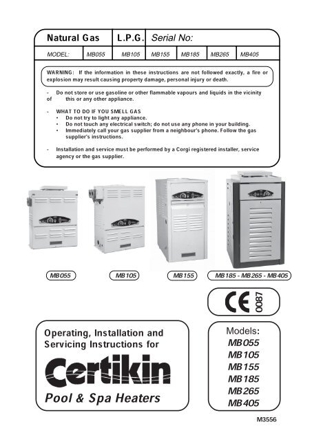
Natural Gas L.P.G. Serial No:MODEL: MB055 MB105 MB155 MB185 MB265 MB405WARNING:explosion mayIf theresultinformationcausing propertyin thesedamage,instructionspersonalareinjurynot followedor death.exactly, a fire or-ofDo notthisstoreor anyorotheruse gasolineappliance.or other flammable vapours and liquids in the vicinity- WHATDoTOnotDOtryIF YOUlightSMELLany appliance.GAS•DoImmediatelynot touchcallanyyourelectricalgas supplierswitch;fromdo nota neighbour'suse any phonephone.in yourFollowbuilding.supplier's instructions.the gas-agencyInstallationor theandgasservicesupplier.must be performed by a Corgi registered installer, serviceMB055 MB105 MB155 MB185 - MB265 - MB405Operating, Installation andServicing Instructions for<strong>Pool</strong> & <strong>Spa</strong> <strong>Heaters</strong>0087Models:MB055MB105MB155MB185MB265MB405M3556
GENERAL SPECIFICATIONSWATER CONTENT Litre Model 0.8 Model 1.1 Model 1.8(gal) 055 (0.18) 105 (0.3) 155 (0.4)Model 1.9 Model 1.9 Model 2.6185 (0.4) 265 (0.4) 405 (0.5)MAXIMUM WATER PRESSURE8 bar (125 psi)MAXIMUM WATER FLOW TEMP 45.0 °C 110 (°F)ELECTRICAL SUPPLYPERFORMANCE SPECIFICATIONS - NATURAL GAS230V 50Hz, FUSED AT 3A. POWER 100WGAS CATEGORY, TYPE AND SUPPLY PRESSURE II2H3+G20 @ 20 mbar (8 in. wg)MODEL 055 105 155 185 265 405Corgi Work Code 1014357 1014358 1014359 1014360 1014361 1014362BURNER mbar 6.3 6.8 7.7 8.1 8.3 8.7PRESSURE (in. wg) ( 2.5 ) ( 2.7 ) ( 3.1 ) (3.2) (3.3) (3.5)HEAT GROSS kW 12.9 26.67 38.98 49.53 71.5 108.4INPUT (Btu/h) (44,000) (91,000) (133,000) (169,000) (244,000) (370,000)NET kW 11.6 24.0 35.08 44.58 64.4 97.6(Btu/h) (39,600) (81,900) (119,700) (152,100) (219,600) (333,000)HEAT kW 10.06 20.8 30.4 38.63 55.8 84.58OUTPUT (Btu/h) (34,300) (71,000) (103,700) (131,820) (190,300) (288,600)GAS RATE m 3 /h 1.22 2.5 3.7 4.6 6.6 10.28INJECTOR DIA. mm 1.78 1.78 1.85 1.78 1.78 1.78&(MARKING) gauge (50) (50) (49) (50) (50) (50)NUMBER OF BURNERS 4 8 10 13 19 29& INJECTORSPERFORMANCE SPECIFICATIONS - LPGGAS CATEGORY, TYPE AND SUPPLY PRESSURE II2H3+G30 @ 30 mbar, G31 @ 37 mbar055MODEL Easiheat 055 105 155 185 265 405Corgi Work Code 1014374 1014375 1014376 1014377 1014378 1014379HEAT GROSS kW 14.65 12.9 26.67 38.98 49.53 71.5 108.4INPUT (Btu/h) (50,000) (44,000) (91,000) (133,000) (169,000) (244,000) (370,000)NET kW 13.2 11.9 24.54 35.86 45.57 65.8 99.8(Btu/h) (45,000) (40,500) (83,720) (122,360) (155,480) (224,480) (340,400)HEAT kW 11.0 10.06 20.8 30.4 38.63 55.8 84.58OUTPUT (Btu/h) (37,400) (34,300) (71,000) (103,700) (131,820) (190,300) (288,600)GAS RATE m 3 /h 0.50 0.47 0.97 1.43 1.82 2.57 4.04INJECTOR DIA. mm 1.01 0.99 0.99 1.01 1.01 1.01 1.01&(MARKING) gauge (60) (61) (61) (60) (60) (60) (60)NUMBER OF BURNERS 4 4 8 10 13 19 29& INJECTORSEASIHEAT NOTE: The Easiheat will use about 1kg of Propane for every hour of continious running.U.K. & Europe Table A .24-06-05
ContentsINSIDE COVER - GENERAL & PERFORMANCE SPECIFICATIONS2 PART ONE - USER'S OPERATING INSTRUCTIONS2 SECTION 1 / START-UP PROCEDURES2 Before Start-Up3 Operating Models 055, 105 AND 1554 Operating Models 185, 265 and 405After Start-Up5 SECTION 2 / CAUTION5 SECTION 3 / MAINTENANCE & CARE PROCEDURE6 <strong>Pool</strong> & <strong>Spa</strong> Water Chemistry6 Cold Weather Operation6 Winterizing the <strong>Pool</strong> & <strong>Spa</strong> Heater7 PART TWO - INSTALLATION/SERVICE INSTRUCTIONSSECTION 1 / RECEIVING EQUIPMENT7 SECTION 2 / INSTALLATION INSTRUCTIONS11 Outdoor <strong>Heaters</strong>11 Indoor <strong>Heaters</strong>14 Combustion Air15 Gas Supply Connections16 Plumbing For Water Connections16 Left Side Water Connection Conversion20 Electrical Wiring23 SECTION 3 / SERVICING INSTRUCTIONS23 General Location of Controls25 Temperature Controls25 Pressure Switch26 High Limit27 Pilot Safety27 Burner Drawer Removal27 Gas Valve Removal27 Main Burner & Orifice Removal27 Pilot Removal & Cleaning28 Heat Exchanger Removal28 Control Immersion Well Replacement28 Tube Cleaning29 Desooting Procedure29 Combustion Chamber Removal29 Unitherm Governor Replacement30 SECTION 4 / TROUBLE SHOOTING GUIDE30 Mechanical32 Models 055, 105 & 155.34 Models 185, 265 & 405.36 SECTION 5 / REPLACEMENT PARTS36 Replacement Parts List - 05538 Replacement Parts List - 10540 Replacement Parts List - 15542 Replacement Parts List - 185, 265 & 405127-01-04
PART ONE - USER'S OPERATING INSTRUCTIONSFOR YOUR SAFETY - READ BEFORE OPERATINGWARNING:EXACTLY, AIFFIREYOUORDOEXPLOSIONNOT FOLLOWMAYTHESERESULT,INSTRUCTIONSPROPERTY DAMAGE, PERSONAL INJURY OR LOSSCAUSINGOF LIFE.SECTION 1 / START-UP PROCEDURESBEFORE START-UPBURNERSClean air louvres of dust, lint and debris. Keepheater area clear and free from combustibles, flammableliquids and chemicals. Do not obstruct theflow of combustion and ventilating air.WATERWater must be flowing through the heater duringoperation. Ensure that system is filled with water andthe pump is operating.055 105155 185 - 265 - 405227-01-04
FOR YOUR SAFETY READ BEFORE OPERATINGWARNING: IFRESULTYOU DOCAUSINGNOT FOLLOWPROPERTYTHESEDAMAGE,INSTRUCTIONSPERSONALEXACTLY,INJURYA FIREOR LOSSOR EXPLOSIONOF LIFE.MAYThiswhichapplianceautomaticallyis equippedlights thewithpilot.an ignitionDo not trydevicethe pilot by hand. to lightBEFOREaround theOPERATINGappliance areaafterfora prolongedgas. Be sureoff,tosmellsmellallnextand willto thesettleflooronbecausethe floor.some gas is heavier than airWHATDo notTOtryDOto lightIF YOUanySMELLapplianceGASDoDo notnottouchuse anyanyphoneelectricin yourswitch* Immediately call your gas supplierbuilding.fromgas supplier'sa neighbour'sinstructions.phone. Follow the* Ifcallyouthecannotfire service.reach your gas supplier,Isolate this is not the accessible, appliance with isolate the at Service the gas Cock meter. inside. IfDoundernotwater.use thisImmediatelyappliancecallif anya qualifiedpart has beenserviceto replaceengineerany parttoofinspectthe controlthe appliancesystem andandany gas control which has been under water.CAUTION: Propane gas is heavier than airand will settle on the ground. Since propanecan accumulate in confined areas, extra careshould be exercised when lighting propaneheaters.OPERATING MODELS 055,105 and 155Quick StartCheck that the Electricity and Gas Supplies areon. Turn on the <strong>Pool</strong> Pump. Turn on the Heaterwith the switch on the Front Panel and set thedesired temperature with the <strong>Pool</strong> TemperatureKnob. In a few seconds the Heater will fire.Summary of Controls (Left to Right)<strong>Spa</strong>TemperatureRangekstop.tifKnobstop Ring<strong>Pool</strong> TemperatureRangeStandbyTemperature<strong>Pool</strong> Temperature Control Knob16°C to 41°C (60°F to 106°F)The <strong>Pool</strong> or <strong>Spa</strong> water temperature is controlledby the <strong>Pool</strong> Temperature Knob, rotate anticlockwiseto increase the <strong>Pool</strong> Temperature.The Knob is fitted with a means of limiting theupper temperature limit below the maximum level.The knob stop adjustment ring illustrated is adjustableby loosening the set screw, rotating theknobstop ring to the desired location andretightening the set screw.High LimitIf the Heater temperature rises too high theHigh Limit Thermostat will operate. Wait untilthe Heater is cool then press 'Reset'. It will clickif it has had to reset. The Heater should nowrun.If this problem persists this should beinvestigated by a Service Engineer.ON/OFF Switch - Turns the Heater On and Offand resets the Ignition Control if locked out. Forlonger periods of isolation the Heater should beswitched off at its Mains supply.318-02-04
OPERATING MODELS 185, 265 and 405Quick StartCheck that the Electricity and Gas Supplies areon. Turn on the <strong>Pool</strong> Pump. Turn on the Heaterwith the switch on the Front Panel and set thedesired temperature with the <strong>Pool</strong> TemperatureKnob. In a few seconds the Heater will fire.Summary of Controls (Left to Right)ON/OFF Switch - Turns the Heater On and Offand resets the Ignition Control if locked out.Lock/Unlock Button - If it is pressed for 2seconds it locks the Set Temperature so the <strong>Pool</strong>Temperature Knob is inoperative. To unlock, pressagain for 2 seconds.With a short press the Set temperature is displayed.It will flash if the Lock is ON.<strong>Pool</strong> Temperature Display - This normally showsthe <strong>Pool</strong> Temperature but also show the SettingTemperature when the <strong>Pool</strong> Temperature ControlKnob is moved. A Setting Dot is displayed whilst itis adjusted. The Display is also used for commissioningand diagnostic purposes.(Page 34)<strong>Pool</strong> Filter Blocked - YellowOn - If the pump is running and there isinsufficient pressure, possibly due to ablocked <strong>Pool</strong> Filter. The Heater will not run.Overheat - RedOn - This indicates the Heater hasoverheated and shutdown. Use the OverheatReset (see below). If this problem persiststhis should be investigated by a ServiceEngineer.Overheat Reset (not on front panel)If the Overheat Indicator has lit the Heater willnot work until the thermostat has been reset.(See page 24 for location)Wait until the Heater is cool then remove thedoor and locate the Overheat Thermostatmounted on its bracket. Press its centre and itwill click.The Red Overheat indicator will go out andthe Heater can now run.<strong>Pool</strong> Demand LED - GreenOff - There is no <strong>Pool</strong> Heating demand, poolheating is off.On - There is <strong>Pool</strong> Heating Demand and the <strong>Pool</strong>is not up to temperature.Flashing - The <strong>Pool</strong> Heating Demand is met, thepool is up to temperature.<strong>Pool</strong> Temperature Control Knob16°C to 32°C or 41°C (60°F to 90°F or 106°F)(Maximum is changed in Setup Mode, see Page 34)Rotate clockwise to increase the <strong>Pool</strong>Temperature. The Setting Temperature is shownwhilst rotating and for 3 seconds after.To lock the required Temperature Setting seeLock/Unlock Button.418-02-04
Software Version 11 and aboveOPERATING MODELS 185, 265 and 405Quick StartSummary of Controls (Left to Right)ON/OFF Switch - Lock/Unlock Button - <strong>Pool</strong> Temperature Display - SEr (Page 34)<strong>Pool</strong> Filter Blocked - YellowOverheat - RedOverheat Reset (not on front panel)<strong>Pool</strong> Demand LED - GreenOffOnFlashing<strong>Pool</strong> Temperature Control Knob(Maximum is changed in Setup Mode, see Page 34)Lock/Unlock Button
AFTER START-UPFeel the inlet and outlet pipes. Outlet pipe should beonly slightly warmer than the inlet. It should not behot.WARNING: Should overheating occur or the gassupply fail to shut off, turn off the manual gas controlto the appliance.VISUAL INSPECTIONWith the heater on, remove the door and make avisual check of the pilot and burner.The flame should be blue with a well-defined pattern.4" MAX100MMMAIN BURNER FLAMEPILOT BURNER FLAMEflame.tifeuropilot2.tifA yellow or "floating" flame indicates restricted airopenings or incorrect injector size. Should thisoccur, shut the heater off and contact your installeror gas supplier.WATER PRESSURE SWITCHA water pressure switch is provided in the heaterto shut off the burners in the event that watersupply to the heater is interrupted. It is veryimportant to verify that the switch electricallyopens and shuts off the gas valve when water flowto the heater is interrupted. Otherwise, rapid andsevere damage is likely to occur to the heater.(The water pressure switch should be checkedand adjusted for proper operation by a qualifiedservice person at the time of installation checkedthereafter.WARNING: Operation of the heater without watercirculation will cause rapid and severe damage tothe heater.5SECTION 2 / CAUTIONElevated water temperature can be hazardous, andthe U. S. Consumer Product Safety Commissionrecommends the following guidelines:1. <strong>Spa</strong> or hot tub water temperatures shouldnever exceed 40°C (104°F). A temperature of 38°C(100°F) is considered safe for a healthy adult.Special caution is suggested for young children.2. Drinking of alcoholic beverages before or duringspa or hot tub use can cause drowsiness whichcould lead to unconsciousness and subsequentlyresult in drowning.3. Pregnant Women Beware! Soaking in waterover 39°C (102°F) can cause fetal damage duringthe first three months of pregnancy resulting in thebirth of a brain-damaged or deformed child.Pregnant women should stick to the 38°C (100°F)maximum rule.4. Before entering the spa or hot tub, users shouldcheck the water temperature with an accuratethermometer; spa or hot tub ther mostats mayerr in regulating watertemperatures by as muchas 2°C (4°F).5. Persons with a medical history of heart disease, circulatory problems, diabetes, or bloodpressure problems should obtain a physician'sadvice before using pools or hot tubs.6. Persons taking medications which inducedrowsiness, such as tranquilizers, antihistamines,or anticoagulant, should not use spas or hot tubs.SECTION 3 / MAINTENANCE ANDCARE PROCEDURESThis heater casing is Polyester powder on top ofzinc coated steel to assist in resisting corrosion. It isrecommended that periodically the casing iscleaned and sprayed with WD40 or similar liquidespecially when installed outdoors. Exposedthreads on manifolds will benefit from a light coatingof grease. Outdoor tops are finished with a specialblack high temperature coating and as this is part ofthe flueing system, subject to high temperaturesand the elements, can discolour and corrode over aperiod of time.A full service by a competent person (i.e. CORGIregistered) should be conducted at least once ayear.1. Inspect top of heater and drafthood for soot, (asticky black substance around finned tubes and "V"baffles), and open flue gas passage ways. Ifsoot is present, contact installer or service agent.2. Inspect and operate all controls, gas valve andpressure relief valve.27-01-04
Software Version 11 and aboveAFTER START-UPWARNING: Should overheating occur or the gassupply fail to shut off, turn off the manual gas controlto the appliance.4" MAX100MMflame.tifeuropilot2.tifWATER PRESSURE SWITCHWARNING: Operation of the heater without watercirculation will cause rapid and severe damage tothe heater.SECTION 2 / CAUTION Pregnant Women Beware! SECTION 3 / MAINTENANCE ANDCARE PROCEDURES
3. Make visual check of the burner and pilotflame. Flame pattern on the main burner and pilotis indicated in the previous illustration. Yellowflame means restriction of the air openings. Liftingor blowing flame indicates high gas pressure. Lowflame means low gas pressure. Should this occur,shut the heater off and contact your gas supplieror qualified service agency.4. On indoor heaters, clean room intake openingsto assure adequate flow of combustion andventilation air.CAUTION: Combustion air must not becontaminated by corrosive chemical fumes whichcan damage the heater and void the warranty.5. Keep area around heater clear and free fromcombustible materials, gasoline and otherflammable and corrosive vapours and liquids.POOL & SPA WATER CHEMISTRYIMPORTANT! These <strong>Heaters</strong> are not suitable foruse on Salt Chlorinated pools. If this is intendedplease contact the Manufacturer.Chemical imbalance can cause severe damage toyour heater and associated equipment. Maintainyour water pH between 7.4 and 7.8 and totalalkalinity between 100 and 150 p.p.m. If themineral content and dissolved solids in the waterbecome too high, scale forms inside the heatexchanger tubes, reducing heater efficiency andalso damaging the heater. If the pH drops below7.2, the heater will be severely damaged. This willresult in corrosion of the heat exchanger. Heatexchangerimbalance isdamagenot coveredresultingby thefromwarranty.chemicalAUTOMATIC CHLORINATORS AND CHEMICALFEEDERSAll chemicals must be introduced and completelydiluted into the pool or spa water before beingcirculated through the heater. Do not placechlorine tablets or bromine sticks in the skimmer.High chemical concentrations will result when thepump is not running (i.e. overnight).Chlorinators must feed downstream of the heaterand have an anti-siphoning device to preventchemical back-up into the heater when the pump isshut off.COLD WEATHER OPERATIONMODERATE CLIMATE: Heater operation can continueduring short term cold spells. When temperaturesare below freezing, flow (continuous pumpoperation) must be maintained.CAUTION: Do not use the heater to maintain watertemperatures just above freezing or for freeze protection.When heater is used during freezingweather, care must be taken to avoid freeze ups.Continuous pump operation is a must. Additionalprotection may be required. The heater is notwarranted against freeze ups.COLD CLIMATE: Prolonged operation with watertemperatures below 10°C (50°F) is notrecommended. When starting the heater with pooltemperatures below 10°C (50°F) operate the heatercontinuously until higher temperatures are reached.Operating the heater for prolonged periods with poolwater below 10°C (50°F) can seriously damage theheater, and is not covered by the warranty.For cold climate areas, please follow the winterizingprocedures listed.WINTERIZING THE POOL & SPA HEATERWhen heaters installed outdoors in freezing climateareas are to be shut down for the winter, observe thefollowing step-by-step procedure:1. Turn off gas valve, manual gas valve, andelectrical supply to the heater.2. Open drain cock located on the inlet/outletheader, (under water pipes). Remove drainplug from return header. Remove the heatexchanger inspection panels on the side oppositewater piping to gain access to theplug on the return header.Return Headerplug.tifDrainPlugNOTE: High chemical concentrates from feedersand chlorinators that are out of adjustment willcause very rapid corrosion to the heat exchanger inthe heaters. Such damage is not covered under thewarranty.63. Disconnect compression fittings from thepressure switch and return header that connectsto the 1/4" copper tube and allow thetube to drain.27-01-04
PART TWO - INSTALLATION/SERVICE INSTRUCTIONSECTION 1 / RECEIVING EQUIPMENTWARNING: This appliance must be installed and serviced by a CORGI registered installer.On receipt of your equipment it is suggested that you visually check for external damage to the carton. If thecarton is damaged, a note should be made on the delivery note when signing for equipment. Remove theheater from the carton and if it is damaged, report the damage to the carrier immediately. Save the carton.These items are shipped loose inside the carton:In the 055 & 105 heaters:1. CPVC Adaptors (2)2. Plastic Gaspipe Flange (1)In the 155 heater:1. In/Out Flanges (2)2. 1-1/2" Flange Gaskets (2)3. 2" Flange Gaskets (2)4. Flange Bolts (4)5. 2" CPVC Adapters (2)In the 185, 265 and 405 heaters:1. Demountable adapters (2)2. O Rings (2)Be sure that you receive the number of packages indicated on the delivery note.When ordering parts, you must specify model and serial number of heater. When ordering under warrantyconditions, you must also specify date of installation.It is recommended that this manual be reviewed thoroughly before installing your pool/spa heater. If thereare any questions that this manual does not answer, please contact the supplier.All heaters are inter-changeable and can be used either indoor or outdoors. The appropriate top designatedfor that type of use is required. If desired, the top can be changed at a later date to change from outdoor toindoor or vice versa.CAUTION: It is perfectly normal during the first hours of operation for the ceramic boards in the combustionchamber to give off unpleasant odours. This clears permanently after three or four hours.Ensure the heater is properly and adequately ventilated during this period.730-09-04
SECTION 2 / INSTALLATIONINSTRUCTIONSIMPORTANT NOTICEThese instructions are intended for the use of qualifiedpersonnel only, specifically trained and experiencedin the installation of this type of heating equipmentand related system components. Installationand service personnel must be CORGI registered.Persons not qualified must not attempt to fix thisequipment nor attempt repairs according to theseinstructions.WARNING:Improper installation, adjustment, alteration, serviceor maintenance may damage the equipment, createa hazard resulting in asphyxiation, explosion or fire,and will void the warranty.STATUTORY REQUIREMENTSGas Regulations, Safety (Installation 1994 and Use)It is the law that all gas appliances are installed bycompetent persons in accordance with the aboveregulations. Failure to install appliances correctlycould lead to prosecution. It is in your own interest,and that of safety, to ensure that the law is compliedwith.General RequirementsThe appliance must be installed by a competentperson ie. CORGI registered in accordance with therelevant requirements of the Gas Safety Regulations,current I.E.E. Regulations, Model Water Byelaws,Local Water Authority Byelaws and any relevantrequirements of the local gas supplier, local authorityand the relevant British Standard Codes of practiceand Building Regulations. Manufacturers notes mustnot be taken in any way as overriding statutoryobligations. Typical documents include:Models 055, 105 & 155BS. 5440:1 Flues (for gas appliances of rated input notexceeding 60 KW).BS. 5440:2 Ventilation (for gas appliances of rated input notexceeding 60KW).BS. 5449 Forced circulation hot water systems.BS. 6798 Installation of gas fired hot water boilers ofrated input not exceeding 60 KW.BS. 6891: Installation of low pressure pipework.Health & Safety Document No. 635.The Electricity at Work regulations, 1989.CP341; Water Supply.British Gas Publications:IM2; Purging Procedures of Non-domestic Gas InstallationsIM5, Soundness Testing Procedures for Industrial andCommercial Gas Installations.8Models 185, 265 & 405BS. 6891; Installation of low pressure pipework.BS. 6644; Installation of Gas Fired Hot WaterBoilers 60kW to 2MW.CP 341; Water Supply.British Gas Publications:IM2; Purging Procedures on Non-domesticGas Installations.IM5; Soundness Testing Procedures forIndustrial and Commercial Gas Installations.IM11; Flues for Commercial and IndustrialGas Fired Boilers and Air <strong>Heaters</strong>.Model Water Byelaws.This appliance must be installed externally in open air(without a flue) or indoors (with a suitable flue system)in a room separated from living rooms and providedwith appropriate ventilation direct to the outside.The appliance must be used only in accordance withthese instructions. Incorrect use is dangerous andinvalidates all warranties and Certification.Conversion Instructions.The heater is supplied in two versions,one for usewith Natural Gas, G20 at 20 mbar inlet pressure, theother for Propane, G31 at 37 mbar. If it is necessaryto convert the heater for use on the other gas theappropriate conversion kit must be purchased andfitted using the instructions provided.NOTE: The heater should not be located in an areawhere possible water leakage will result in damageto the area adjacent to the appliance or to thestructure. When such locations cannot beavoided, it is recommended that a suitable drain pan,adequately drained, be installed under the appliance.The pan must not restrict combustion air flow.BASE INSTALLATIONHeater must be mounted on a level base, such ascement slab, cement blocks or other non-combustiblesurface. An alternative method for providing abase for combustible floors is illustrated below.<strong>Heaters</strong> must not be installed on carpeting.12" Min.300mmbase.tif4" Min.100mm12" Min.300mmSheet Metal24 Gauge0.7mmHollow concrete cinder block, align holes andleave ends open. Alternative method for providinga non-combustible base.01-10-98
CLEARANCESALL HEATERSFor clearances from combustible surfaces, see thechart below.CLEARANCEMATERIAL (mm)FROM COMBUSTIBLEPlant Room InstallationTop Back Right Left FrontModel055 900 50 150 150 Clear105 900 50 150 150 Clear155 1050 300 150 300 Clear185-405 750 150 300 150 ClearOutdoor InstallationTop Back Right Left FrontModel055 Clear 50 150 150 Clear105 Clear 50 150 150 Clear155 Clear 300 150 150 Clear185-405 Clear 150 150 150 ClearFor servicing, provide at least 600mm (24") in front ofthe heater for burner tray removal, and at least450mm (18") on water connection side of the heaterto inspect and delime the heat exchanger.<strong>Heaters</strong> must not be installed under an overhang ofless than 1.0m (3 feet) from the top of the heater.Three (3) sides must be open in the area under theoverhang. Roof water drainage must be divertedaway from the heaters installed under overhangs withthe use of gutters:The point from where the flue products exit the heatermust be a minimum of 1.25m (4 feet ) below, four (4)feet horizontally from or 0.3m (1 foot) above anydoor, window or gravity inlet to a building. The topsurface of the heater shall be at least 1.0m (3 feet)above any forced air inlet, or intake ducts locatedwithin 3.0m (10 feet) horizontally.HIGH WIND CONDITIONS(OUTDOOR HEATERS ONLY)In areas where high winds are frequent, it may benecessary to locate the heater a minimum of 1.0 mfrom high vertical walls, or install a wind break so theheater is not in direct wind current.1.25m1.25m4' Min4'Min1.25m4'MinForced AirInlet1.0m 3' Min0.3m1' Min3.0m10'Min.clear.tif901-10-98
OUTDOOR HEATERSThese heaters are certified by Advantica for outdoorinstallation, when equipped with the approved topsdesignated for outdoor use.WARNING: The heater shall not be located in an areawhere water sprinklers, or other devices, may causewater to spray through the cabinet louvres and intothe heater. This could cause heavy internal rusting ordamage some electrical components, and this wouldvoid the warranty.105 & 155 ModelsFLUE TERMINAL (Outdoor) Stackless Top IllustrationTop VentOpeningIt is recommended that the casing is cleaned andsprayed with WD40 or similar liquid, and exposedthreads on the manifolds are lightly coated in grease,after assembly.Heater withOutdoorStackless TopHeater Vent OpeningJacket Top185, 265 & 405 ModelsFLUE TERMINAL (Outdoor) Stackless Top IllustrationFLUE CONNECTIONS AND DIMENSIONS055 ModelsFLUE TERMINAL (Outdoor) Stackless Top Illustration1. Insert tabs into keyhole (4 places).Pagoda Top(ShippedLoose withHeater)1: Remove the (8) screws which fasten jacket topto heater.2: Line up top vent opening over heater ventopening3: Lower outdoor top onto unit lining up slots inoutdoor top with screw holes in jacket top.4: Reinstall (8) screws to secure jacket top andoutdoor top to unit.Press tabto locatetab1.tif2. Snap tabs into keyholes so as not to pull out.055expl1.tiftab2.tif1008-08-01
INDOOR HEATERThe design is also certified by Advantica for indoorinstallation when fitted with the appropriate draughtdiverter and a suitable flue system to outside. Notethat the heater must be in a room separated fromliving rooms and provided with appropriate ventilationdirect to the outside.055 ModelsFLUE TERMINAL (Indoor) Draught DiverterIllustrationLocate and assemble as shown. Secure with screwssupplied in envelope inside carton.MountingScrewsDraughtDiverter185, 265 & 405 ModelsFLUE TERMINAL (Indoor) Draught DiverterIllustration1. Remove the louvred jacket top by removingfour (4) No.10 flat head screws.2. If originally installed, remove "Pagoda" topfrom the louvered jacket top.3. Place the inner stack adapter panel over theflue collector inside the heater. Make surethe flanged side of the flue opening is up.4. Turn the stack (diverter) upside down and set itdown bottom side up.5. Turn the jacket top panel (removed in step 1)down and place it through the stack.6. Attach the three (3) mounting brackets to thestack using the screws provided and the holesthat are pre-drilled in the stack.brackets are positioned with theMakeflangesurenearthethe top side of the stack (see illustrationbelow).Caution must be taken not to over tighten andstrip the screw threads.7. Turn the assembled stack and jacket top, rightside up. The jacket top will be trappedbetween the brackets and the top of the stack.Place the stack over the inner adapter panelflanged hole and lower the louvered jacket toppanel back into its original position. Reinstall thefour (4) No.10 flat head screws removed instep 1 above.055expl2.tif105 & 155 ModelsFLUE TERMINAL (Indoor) Draught DiverterIllustrationLocate and assemble as shown. Secure with screwssupplied in envelope inside carton.DraughtDiverterJacketTopMountingScrews (8)Screw HoleLocation3.25"82.5mmDraughtDiverterJacket Top Panel(Part of Heater)No.10 Screw (3)Mounting Bracket (3)Inner StackAdapter PanelFlue Collector(Part of Heater)term.tifS896011405term.tif01-10-98
SPECIFICATIONS & DIMENSIONS 055 - 105 - 155MODEL FLUE DIA CONNECTIONS SHIPPING WEIGHTGAS WATER kg (lbs)mm (in.) APPLIANCE DIVERTER055 100 (4) ½" 1½" NPT 31.8 (70) 2.3 (5)105 127 (5) ½" 1½" NPT 48 (105) 3.5 (8)155 152 (6) ¾" 2" NPT 62 (135) 3.5 (8)DIMENSIONS - 055 Model Only130mm(5 -1/8")60mm(2 - 3/8")825mm(32 - 1/2")620mm(24 - 1/2")455mm(18")525mm(20 - 3/4")Gas Connection65mm(2 - 1/2")325mm(12 - 7/8")475mm(18 - 3/4")DIMENSIONS - 105 Model Only190mm(7 - 1/2")85mm(3 - 3/8")1070mm(42")835mm(32 - 7/8")610mm(24")690mm(27 - 1/4")65mm(2 - 1/2")GasConnection325mm(12 - 3/4")510mm(20")122/06/04
DIMENSIONS - 155 Model Only220mm(8 - 3/4")85mm(3 - 3/8")900mm(35 - 1/2")680mm(26 - 3/4")770mm(30 - 3/8")1140mm(44 - 7/8")GasConnection390mm(15 - 3/8")370mm(14 - 1/2")610mm(24")SPECIFICATIONS & DIMENSIONS 185 - 265 - 405MODEL WIDTH FLUE DIA CONNECTIONS SHIPPING WEIGHT(A) (B) GAS WATER kg (lbs)185 464 (18 1/4) 150 (6) ¾" 2" NPT 86.8 (191) 5.5 (12)265 568 (22 3/8) 175 (7) ¾" 2" PLASTIC 97 (214) 7 (15)405 743 (29 1/4) 230 (9) ¾" 2" PLASTIC 115 (253) 9 (20)mm (in.) mm (in.) APPLIANCE DIVERTER(B)(C)INDOOR DRAUGHTHOOD185 1590 mm (62 5/8 ")265 1597mm (62 7/8 ")405 1570mm (61¾")111mm(4-3/8")247mm(9¾")965mm(38")673mm(26 ½")1015mm(40")336mmGas Connection (13-1/4")*540mm(*21-1/4")A675mm (26-1/2")*Electrical Connection On Left Side is 486mm (19-1/8")132-06-04
CAUTION: NOTE:FLUE SYSTEMWARNING: Flue.pcxModel Input Plant Room (cm²)ref.ref.BS6644BS5440forformodelsmodelsoverunder60kW60kW(kW) High InsideLow High Outside Low105 055 13 27 117 243 486 234 122 59 117155 39 351 702 176 243185 50 450 900 225 351 450265 405 72 108 - - 297 378 600 756
GAS SUPPLY CONNECTIONSGas piping must have a manual shut-off valve locatedoutside the heater jacket. All gas piping should betested after installation in accordance with localcodes.CAUTION: The heater and its manual shut off valvemust be disconnected from the gas supply during anypressure testing of that system at test pressures inexcess of 150mbar (2.2psi). Dissipate test pressurein the gas supply line before reconnecting the heaterand its manual shut off valve to gas supply line.FAILURE TO FOLLOW THIS PROCEDURE MAYDAMAGE THE GAS VALVE. OVER PRESSUREDGAS VALVES ARE NOT COVERED BY WAR-RANTY. The heater and its gas connections shall beleak tested before placing the appliance in operation.Use soapy water for leak test. DO NOT use openflame.NOTE: Do not use PTFE tape on the gas line pipethread. A flexible sealant is recommended.Models 055 and 105 are fittef with a ½" BSP gascock,all others have a ¾" gascock.A minimum of 20 mbar (8”) WG and a maximum of 22mbar (8¾”) W.G.upstream pressure under load, andno load conditions are provided for natural gas or aminimum of 37mbar (14¾”) W.G.and a maximum of45 mbar (18”) W.G for propane gas.GAS PRESSUREFor LPG <strong>Heaters</strong> the gas pressure is regulated bythe injectors fitted in the factory. There is noadjustment.For NG <strong>Heaters</strong> the regulator on the gas valve isfactory set. If adjustment is required, remove thecap and turn the adjustment screw clockwise toincrease and counter-clockwiese to decrease theburner pressure.Honeywell Gas ValveBurner PressureadjustmentPIPE SIZING FOR GAS CONNECTIONSMAXIMUM EQUIVALENT PIPE LENGTH METRESN - NATURAL GAS @ 1.0 mbar PRESSURE DROPP - L.P.G. @ 2.5 mbarPRESSURE DROP10mm 15mm 22mm 28mmMODEL N P N P N P N055 6 12 15105 3 5 20155 10.5 >24 36185 8 >24 29265 4.5 18 14.5405 8.5 7152-06-04
PLUMBING FOR WATER CONNECTIONSLEFT SIDE WATER CONNECTION CONVERSION185, 265 & 405 Models OnlyexchangerThere are twoor,waysswappingof achievingof the headers.the connection conversion. Removal and turning of the heatGenerally swapping headers is easier and this process is described here.1. Remove the right and left side access panels (Fig.1 & 2)2. Withdraw the temperature and overheat sensors from their pockets (beware of the heatsink compound) anddisconnect the connections to the pressure switch and the overheat thermostat.3. Re-route the sensors and cables to the other side.4. Remove the 12 bolts holding the Headers to their respective tubesheets.5. Clean the mating surfaces for the header gaskets and the gaskets themselves.(NB. Use only silicone grease as a lubricant)6 Fit the headers on their new sides ensuring they are square and correctly compressing the gasket.7. Refit the sensors and connectors to the safety devices.8. Re-commission and check for leaks.9. Replace the side access panels.Fig. 1Fig. 21630-09-04
This page is intentionally left blank1730-09-04
CONNECTIONSAll ModelsLOCATION2" CPVC AdaptersThe heater requires water flow and pressure tooperate properly. It must therefore be installeddownstream of the discharge side of the filter andpump. A typical installation is plumbed as follows:1. The Pump outlet is plumbed to the inlet of the Filter.2. The outlet side of the Filter is then plumbed to theinlet of the Heater.mbsmall.tifInlet/Outlet HeaderPVC PipeBMRA3. The outlet of the Heater is plumbed to the return lineto the pool or spa. The Pump, Filter and Heater areplumbed in series.Plumbing from the heater back to the pool must nothave any valves or restriction that could prevent flowwhen the pump is operating.Use the pressure loss chart below to specify asuitable pump.PRESSURE LOSS CHART 055 / 105 / 155 MODEL ONLY50040030020010000 100 200 300 400LITRES / MINHeater must be located so that any water leaks will notdamage the structure of adjacent area. High temperature2" plastic pipe (CPVC) may be threadeddirectly into the Cast Iron header flanges. This is notthe same as the Schedule 80 PVC pipe which is alsocoloured grey. PVC may be used immediately afterthe CPVC adapters.NOTE:If operating pressure above 2 bar (30psi) areencountered then connection pipes must either bescrewed into the flange or suitably anchored.CAUTION: NEVER install PVC directly into Cast Ironheader flanges.FLOW RATESMINIMUM/min. MAXIMUM/min.MODEL PIPE SIZE Litres (Gals) Litres (Gals)055 1-1/4"-1-1/2" 77 (17) 225 (50)105 1-1/4"-1-1/2" 77 (17) 220 (49)155 1-1/4"-1-1/2" -2" 77 (17) 430 (95)185 1-1/4"-1-1/2" -2" 77 (17) 470 (104)265 1-1/4"-1-1/2" -2" 95 (21) 470 (104)405 1-1/4"-1-1/2" -2" 150 (33) 470 (104)MBARPRESSURE LOSS CHART 185 / 265 / 405 MODELS ONLY6005004003002001000 100 200 300 400LITRES / MIN*When flow rates exceed maximum an externalauxiliary bypass valve is required. See externalbypass valve section for details.COMPANION FLANGE CONNECTIONSDO NOT use petroleum base assembly fluids (suchas Petroleum Jelly or lubricating oil). If assembly lubeis required, use a silicone grease.055 Model OnlyThe inlet/outlet header flange accepts a 1½"copperconnectiontubedirectlyor 1¼"intogalvanizedthe manifold.pipe asThea slipalso threaded for 1½" pipe thread.flange is1810-11-05
DAN MAINES055 Models OnlyINOUT185, 265 & 405 Models Only055hdr.tif105 Model OnlyThe 105 accepts direct connection to 1½" plastic pipeusing the adapters provided.Inlet/Outlet Header155 Model OnlyInlet/Outlet HeaderInout.tif1½" NPTInlet/OutletConnectionsIN1 2Flange GasketHeader FlangeThere are two sets of flange gaskets supplied withyour heater. Use the appropriate gaskets for all yourheater connections. Discard unused set.DESIGN 1: Accepts 1½" copper tube or 1¼"galvanized pipe as a slip connection.DESIGN 2: Accepts 2" copper tube as a slipconnection. The flange is threaded for 2" screw in pipeconnections. Also used with the 2" CPVC adapters.gasket.tifOUT105 headers.tifEnsure the O rings are properly seated beforetightening hand tight. They maybe lubricated withsilicone grease. Glue plastic pipe directly in to theunions.UNITHERM GOVERNOR OPERATIONDoes not apply to 105 ModelThe patented Unitherm Governor is a thermostaticmixing valve specifically designed to maintain constantheater internal temperature between 40.6 to46.1°C despite continually changing flow rates fromthe filter and changing pool temperatures. Thisnarrow range is needed to prevent damagingcondensation on the burners which will occur if theheater runs for any length of time below 37.8°C. It isalso needed to inhibit scale formation in the tubes bymaintaining temperatures well below acceleratedscaling temperatures.INTERNAL AUTOMATIC BY-PASS VALVEDoes not apply to 055 ModelIn addition to the Unitherm Governor, a built-in automaticby-pass valve is provided in the in/out header.While the Unitherm Governor responds to thechanges in water temperature in the heater, theinternal by-pass valve automatically responds tochanges in water pressure in the piping system.Proper amount of water flow is maintained throughthe heater under varying pressures dictated by theconditions of the pump and filter.ugov.tifS801930-09-04
NOTE:Heater is equipped with an electronic ignition devicewith a 100% safety lockout feature. If the heater failsto start or lockout, reset the ignition device by interruptingthe power to the heater for 1 0 seconds.Caution: If service replacement of the electronicignition device is required, replace only with theignition component supplied as a required spare. ELECTRICAL WIRING NOTEIf it is necessary to replace any of the originalwiring, it must be replaced with 105° C wire or itsequivalent, except all black wire which must be replacedwith 150° C wire or its equivalent.INTERNAL WIRINGGREEN/YELLOWBLUEBROWNNLINSTALLER WIRINGNOTE: <strong>Heaters</strong> are factory wired for 230V powersupply.NOTE: 22mm Dia. holes not utilized on jacket andcontrol box can be used for fireman switch or auxiliarycontrol interface wiring.NOTE:
WIRING DIAGRAM 055-105-155 MODELS ONLYABBEY IGNITION DEVICEKEYL N EBK- BLACKBR- BROWNR- REDY- YELLOWG/Y- GREEN &YELLOWBL- BLUEPILOTY230 VBRBTRANSFORMERTR GNDY1PV / MVGNDYPV/MV & AC NEUTRALEARTHG/YY24 VWITH THERMAL FUSENON-REPLACEABLE3 AMPFUSEABBEY FAULT INDICATIONSNo of flashes between pauses1SOLID STATETHERMOSTATPOTSEN124VCOMN.OHI-LIMITPOTENTIOMETERRBkMANUALSWITCHRANCOHI-LIMITPRESSURESWITCHTHERMALFUSEMANUALRESETGAS VALVETEMP SENSORMVPV5, 7 and 10BkMVAC 24 VOLTSLed13, 14 and 1516, 17 and 18FAILED TO LIGHTFLAME DETECTION FAILEDPILOT VALVE FAILEDMAIN VALVE FAILEDReset by turning supply off, then onROBERTSHAW FAULT INDICATIONSOFFFLASHINGOFF orFAILED INTERNAL CHECKFAILED TO LIGHT PILOTONOK, WORKINGReset by turning supply off, then onG/YY10YYYTH 24PVLedABBEY ROBERTSHAW30/09/04BkBkBkBkBkBkBkBkBkBk2130-09-04
WIRING DIAGRAM 055-105-155 MODELS ONLYKEY
WIRING DIAGRAM 185-265-405 MODELS ONLY KEY
TEMP SENSORTHERMALFUSERANCOHI-LIMITMANUALRESETHI-LIMITPRESSURESWITCHBBr724 23 22 21 20 19MANUALSWITCHGyOr BR W V Or P18 17 16 15 14 13 12 11 10 9 86Y5230 VBrYBkBk43L N EBG/YG/YGAS VALVEPILOTTRANSFORMERWITH THERMAL FUSEY24 V3 AmpsY2YBkROr101PV/MV & AC NEUTRALEARTHMVPVAC 24 VOLTSLedYYG/YROrBkTR GNDPV / MVGNDMVPVTH 24LedABBEYROBERTSHAWABBEY FAULT INDICATIONSNo of flashes between pauses15, 7 and 1013, 14 and 1516, 17 and 18FAILED TO LIGHTFLAME DETECTION FAILEDPILOT VALVE FAILEDMAIN VALVE FAILEDReset by turning supply off, then onROBERTSHAW FAULT INDICATIONSOFFFLASHINGONOFF orFAILED INTERNAL CHECKFAILED TO LIGHT PILOTOK, WORKINGReset by turning supply off, then on2/11/051WIRING DIAGRAM 185-265-405 MODELS ONLYABBEY IGNITION DEVICEKEYBk- BLACKBr- BROWNR- REDY- YELLOWG/Y- GREEN &YELLOWBl- BLUEOr- ORANGEV - VIOLETGy - GREY222-11-05
SECTION 3 / SERVICING INSTRUCTIONSGENERAL LOCATION OF CONTROLS055 MODELManual High LimitReset Button105 MODELPressure SwitchDrain ValveUnithermGovernor(Bronze Units Only)Burners & PilotGas ValveBypass ValveHigh Limits& OverheatThermostats105cont.tifSolid State Thermostat &Ignition Control155 MODELHigh Limits &OverheatThermostatsSolid StateThermostat ControlIgnition ControlPressure SwitchGas ValveThermal FuseUnitherm GovernorDrain ValvePilot238110.tif01-10-98
GENERAL LOCATION OF CONTROLS - continued.185-265-405 MODEL155 ModelCONTROL PANEL REMOVAL1. Remove lower door.2. Remove (2) screws from bottom flange ofcontrol panel.3. Slide down control panel to clear jacket toppanel.4. Rotate control panel down until panel stops.Do not force.NOTE: Caution must be taken not to damagecontrols or wiring.185,265 & 405 ModelsCONTROL PANEL REMOVAL1. Remove (4) screws from sides of controlpanel.2. Rotate control panel down until panel stops.Do not force.NOTE: Caution must be taken not to damagecontrols or wiring.Jacket Top PanelCONTROL PANELControl PanelMOUNTING SCREWS (4)rpdoor.tif8267.tifMounting Screws (2)2430-09-04
185 265 and 405 ModelsOn/OffSwitchThermostatKnob<strong>Pool</strong> Filter Blocked - YellowOn - If the pump is running and there is insufficientpressure, possibly due to a blocked <strong>Pool</strong> Filter. TheHeater will not run.Overheat - RedOn - This indicates the Heater has overheated andshutdown. Reset. If this persists this should beinvestigated by a Service Engineer.Overheat Reset (not on front panel)If the Overheat Indicator has lit the Heater will notwork until the thermostat has been reset. Wait untilthe Heater is cool then remove the door and locatethe Overheat Thermostat mounted on its bracket.Press its centre and it will click.The Red Overheat indicator will go out and theHeater can now run.055, 105 & 155 ModelsSummary of Controls (Left to Right)ON/OFF Switch - Turns the Heater On and Off andresets the Ignition Control if locked out.Lock/Unlock Button - If it is pressed for 2seconds it locks the Set Temperature so the <strong>Pool</strong>Temperature Knob is inoperative. To unlock, pressagain for 2 seconds.With a short press the Set temperature is displayed.It will flash if the Lock is ON.<strong>Pool</strong> Temperature Display - This normally showsthe <strong>Pool</strong> Temperature but also show the SettingTemperature when the <strong>Pool</strong> Temperature ControlKnob is moved. A Setting Dot is displayed whilst it isadjusted. The Display is also used for commissioningand diagnostic purposes.(Page 34)<strong>Pool</strong> Demand LED - GreenOff - There is no <strong>Pool</strong> Heating demand, pool heatingis off.On - There is <strong>Pool</strong> Heating Demand and the <strong>Pool</strong> isnot up to temperature.Flashing - The <strong>Pool</strong> Heating Demand is met, thepool is up to temperature.<strong>Pool</strong> Temperature Control Knob16°C to 32°C or 41°C (60°F to 90°F or 106°F)(Maximum is changed in Setup Mode, see Page 34)Rotate clockwise to increase the <strong>Pool</strong> Temperature.The Setting Temperature is shown whilst rotatingand for 3 seconds after.To lock the required Temperature Setting seeLock/Unlock Button.The pool or spa water temperature is controlled by thepool heater thermostat on the front panel of the heater.The control centre contains an On/Off switch and oneTemperature Control Knob. The switch functions as ameans for turning the heater on or off, however forlonger periods of isolation the Heater should beswitched off at its Mains supply.The Thermostat is fitted with a means of limiting theupper temperature limit below the maximum level.The knob stop adjustment ring illustrated below isadjustable by loosening the set screw, rotating theknobstop ring to the desired location and retighteningthe set screw.25<strong>Spa</strong>TemperatureRangekstop.tifKnobstop RingAll ModelsPRESSURE SWITCHSet Screw<strong>Pool</strong> TemperatureRangeStandbyTemperatureThe pressure switch, or heater actuator, ensures thatthe heater operates only when the filter pump is inoperation.It is factory set at 0.12 bar (1.75 PSI) for deck levelinstallations. When the heater is located below thelevel of the spa or pool, it may be necessary to resetthe pressure switch to compensate for the no-flowstatic head.If it is necessary to reset the pressure switch, werecommend the following procedure:27-01-04
All ModelsPRESSURE SWITCH ADJUSTMENT1. With pump and heater on, turn adjustmentknob (clockwise) until a click is heardfrom the gas valve.2. Turn adjustment knob (counter clockwise)1/4 turn.3. Turn pump off and on several times.Heater should shut off immediately. If it doesnot,repeat steps above until properadjustments is made.AdjustmentKnobpress.tifPRESSURE SWITCH ADJUSTMENT RANGEFLAME ROLL-OUT SAFETY SWITCHrollout.tifThe heater is equipped with a thermal cutoff device toprevent flame roll-out in the event that the heatexchanger becomes blocked. This is a "Single-use"type fusible link or thermal fuse, that must be replacedwhen disabled by an over temperature condition,caused by excessive restriction in the heatexchanger flue passage.HIGH LIMITSAutomaticGas Shut-off HighLimit ThermostatAutomaticResetThermostat1.5 m Max1.5 m Maxrange.tifags.tifManual ResetHigh LimitThermostatautoreset.tiflm7.tifNOTE: If heater is installed outside of the limitsshown, a flow switch must be used in place of thepressure switch when mounted and wired adjacent tothe heater.TWO SPEED PUMPSIn some cases, the flow on the low speed is insufficientto operate the heater. This is apparent when thepressure switch cannot be further adjusted or if theheater makes banging noises. In these cases, thepump must be run at high speed when heating thewater.CAUTION: Do not operate the heater without thefunctionof a properly adjusted pressure switch or flowswitch.The heater is equipped with one manual reset overheatthermostat located in the return header, set toopen at approx. 100°C. the other is the AutomaticGas Shut-off limit, set to open at 57°C and located inthe Inlet/Outlet header.NOTE: An erratic high limit is often characteristic ofinternal heat exchanger problem, i.e. scale buildup,defective bypass. Refer to troubleshooting sections.055, 105 155 ModelsHIGHMOSTATLIMITREMOVAL& MANUAL RESET HIGH LIMIT THER-Disconnect top portion of unit. (See heat exchangerremoval procedure steps 1 thru 7 and step 10).1. Remove Jacket Top,Flue Collector and Baffle.2. Remove defective high limit and replace withnew high limit.2617-08-00
3. To remove the manual reset high limit, follow theprocedure for the high limit thermostat but inaddition, disconnect the electrical connectionsand release its mounting bracket from the sidepanel by removing the M4 nut at the front of thebracket. The thermostat can then be removedfrom its bracket. Ensure thermostat phial iscorrectly located in its pocket.4. Reverse above procedure to reinstall.185, 265 & 405 ModelsMANUAL RESET HIGH LIMIT REMOVAL1. Shut off main electrical power switch toheater.2. Remove inspection panels.3. Disconnect electrical connections fromthermostat.4. Remove defective high limit and replacewith a new high limit. Secure bulb inpocket with chip provided.5. Reverse above procedure to reinstall.HIGH LIMIT REMOVAL (A.G.S.)1. Shut off main electrical powerswitch to heater.2. Remove inspection panels.3. Drain heater.4. Remove defective high limitand replace with a new high limit.5. Reverse above procedure to reinstall.All ModelsPILOT SAFETY IGNITIONThe heater employs a pilot safety which closes themain gas valve within 8/10ths of a second wheneverthe pilot flame is interrupted. Pilot flame is automaticallylit when the device is powered. Unit performs itsown safety check and opens the main valve only afterthe pilot is proven to be lit.BURNER DRAWER REMOVAL1. Shut off main electrical power switch toheater.2. Shut off gas upstream of heater.3. Remove front door.4. Disconnect gas line from gas valve.5. Remove (2) screws that mount burner tray tounit.6. Disconnect wires that terminate at gas valve.7. Slide out burner tray.8. Reverse above procedure to re-install.NOTE:-IMPORTANT Reconnect Earth Connection055, 105 & 155 ModelsGAS VALVE REMOVAL1. Remove burner tray. (See burner drawerremoval procedure).2. Disconnect pilot tubing from gas valve.3. Remove gas valve with manifold from burnertray.4. Remove manifold from gas valve.5. Reverse above procedure to re-install.185, 265 & 405 ModelsGAS VALVE REMOVAL1. Shut off gas supply to the heater. Removegas piping to gas valve inlet.2. Disconnect wires, pilot tubing and bleedline, if required.3. Turn vertical gas pipe from manifoldslightly and unscrew gas valve.4. Reverse above procedure to re-install.All ModelsMAIN BURNER AND INJECTOR REMOVAL1. Remove burner drawer. See burnerdrawer removal procedure.2. Remove screws and burner hold downbracket.NOTE: If the heat exchanger is sooted badly, theburner hold down bracket and spacer can becomedistorted from direct flame impingement and thisusually necessitates replacement of these parts.3. Lift burners from slotted spacers and slidefrom orifices. Clean with a wire brush.4. Orifices usually do not need to bereplaced. To clean, run either copper wireor a drill shank through orifice. Do notenlarge hole. To remove orifice, use asocket wrench and remove from manifold.DO NOT overtighten when reinstalling.055, 105 & 155 ModelsPILOT REMOVAL AND CLEANING1. Remove burner drawer. (See burner drawerremoval procedure).2. Disconnect pilot tubing, disconnect wiresfrom gas valve.3. Disconnect pilot bracket from burner shield.4. Remove pilot from bracket.5. Remove pilot orifice, and clean with wire orsmall brush. CAUTION! DO NOT enlargehole in pilot orifice.6. Reverse above procedure to re-install.2701-10-98
185, 265 & 405 ModelsPILOT REMOVAL AND CLEANING1. Disconnect pilot tubing, and wires fromgas valve.2. Remove pilot assembly from burner tray.3. Remove pilot from bracket.4. Remove pilot injector and clean withwire or small brush. CAUTION! Do notenlarge hole in pilot orifice.5. Reverse above procedure to re-install.HEAT EXCHANGER REMOVAL1. Shut water, gas and electricity off, closevalves and relieve pressure, remove reliefvalve. Remove side inspection panels.2. Remove top holding screws.3. Remove draft diverter, lift and remove topand flue collector. Remove inspectionpanels.4. Loosen bolts and disconnect flange nutson inlet-outlet header, loosen union(s) atgas pipe and slide boiler away from pipinguntil studs clear the header.5. Lift heat exchanger straight up usingcaution not to damage refractory.6. Reverse above procedure to reinstall.055, 105 & 155 ModelsHEAT EXCHANGER REMOVAL1. Shut water, gas, and electricity off, closevalves andrelieve pressure.2. Drain heat exchanger.3. Loosen and remove flange bolts.4. Remove flange and inlet/outlet pipes fromthe header.5. Remove outdoor stackless top or indoorstack top from unit.6. Remove jacket top, flue collector, andbaffles.7. Remove upper front jacket panel, anddisconnect wires at toggle switch.8. Remove capillary bulb from inlet/outletheader.9. Disconnect press switch tube from returnheader.10. Disconnect hi-limit wire from thermostat, andpressure switch. Remove overheatthermostat capilliary & phial.11. Lift heat exchanger straight up fromcombustion chamber, using caution not todamage refractory.12. Reverse above procedure to re-install.All ModelsCONTROL IMMERSION WELL REPLACEMENT1. Shut water off to heater and drain heatexchanger.2. Remove jacket top panel.3. Remove old control well with bushing andsleeve, with 7/8" wrench or socket.4. Slip "o" ring gasket over control well andinstall in header.well.tifOliveWell AssemblyTUBE CLEANING PROCEDURE (Typical)Establish a regular inspection schedule, frequencydepending on local water condition and severity ofservice. Do not let the tubes clog up solidly. Clean outdeposits over 1.5 mm in thickness.The heater must be cleaned from the rear as shown.It is preferable, however, to remove the heatexchanger and the in/out header for better visibilitythrough the tubes and to be sure the ground-up limedust does not get into the system,Note that you do not remove the top panel or the heatexchanger, generally.After reaming, mount the wire brush in place of theauger and clean out debris remaining in the tubes.Another method is to remove the heat exchanger,ream tubes and immerse heat exchanger in noninhibitedde-scale solvent.drill.tif2801-10-98
All ModelsDESOOTING PROCEDURECAUTION: SOOT IS COMBUSTIBLE. EXERCISEEXTREME CARE. NEVER USE A WIRE BRUSH.Soot can clog areas between fins and cause eventualtube failure. Any sign of soot at the base of theburners or around the outer jacket indicates a needfor cleaning.1. Disconnect top portion of unit. (See heatexchanger removal procedure steps 1through 6).2. Remove burner tray (See burner drawerremoval procedure.)3. Take a garden hose and wash heatexchanger,making sure soot is removedcompletely from between fins. Avoidexcessive water against refractory.NOTE: DO NOT WIRE BRUSH.055, 155, 185, 265 & 405 ModelsUNITHERM GOVERNOR (U.G.) REPLACEMENT1. Shut water, gas and electricity off, closevalves and relieve pressure.2. Drain heat exchanger.3. Remove retainer located under outletpipe connection.4. Remove spring and replace old U.G. with anew U.G.5. Reverse above procedure to reinstall.GasketRetainer PlugSpringTo test the operation of the Unitherm Governor, placein hot water (over 43°C) and watch for movementagainst spring. If there is no movement, replace unit.055, 105 & 155 ModelsCOMBUSTION CHAMBER REMOVAL1. Remove heat exchanger (See heatexchanger removal procedure).2. Lift up and remove front and rear refractoryshield.3. Remove refractory panels.4. Reverse above procedure to re-install.Ensure no gaps in cornersRefractory Panels Top View185, 265 & 405 ModelsCOMBUSTION CHAMBER REMOVALTo remove combustion chamber, you must first haveremoved the heat exchanger. Unbolt metal combustionchamber retainer from top and remove combustionchamber panels individually.UniTherm Governorugrep.tifRetainer PlugEnsure no gapsin cornersGasketref265.dwgRefractory Panels Top ViewExtension Pieces (2) Auger with Carbide Tip Wire Brushsoot.tif2927-01-04
SECTION 4 / TROUBLE SHOOTING GUIDEIMPORTANT NOTICE: These instructions are primarily intended for the use of qualified personnel specificallytrained and experienced in the installation of this type of heating equipment and related system components.Installation and service personnel must be Corgi Registered. Persons not qualified shall not attempt to installthis equipment nor attempt repairs according to these instructions.All ModelsMECHANICAL ( FOR QUALIFIED SERVICE PERSONNEL ONLY )PROBLEM CAUSE SOLUTIONHarmonics, or whining noise. U.G. inoperative........................ Check movement by putting into hotwater (43°C or higher). If no movement,replace.*Debris or restriction in system...Locate the restriction and remove.Flush system and clean.*Debris in gas line....................Low flow...................................Remove debris or blow out gas line.Scale forming in heat exchanger - cleanheat exchanger and check pool pH andtotal alkalinity.Heater going on and offcontinuously.Dirty filter.................................. Backwash filter.Low water level in pool...............Raise water level.External bypass setting out ofadjustment................................ Adjust bypass*Pressure switch out ofadjustment................................ Adjust pressure switchLiming or scale forming onheat exchanger.<strong>Pool</strong> water.................................Recommended pH should be between7.4 and 7.8 total alkalinity 100-150 PPMmaximum. Hardness 150-400 PPMmaximum.Sooting High flow rates.......................... Reduce by adding manual bypass valveand adjust by putting thermometer inheader (1/4" NPT) drain opening. Setbypass so thermometer reads between40°C and 43°C.U.G. Inoperative.........................Check movement by putting in hot water(43°C or higher). If no movement,replace.*Air starvation..........................*Improper venting.....................Refer to installation instructions.Follow recommended installationinstructions.*Insects or debris cloggingburner intake ports.....................Clean burners.(* Usually occurs on initial start-up.)3008-08-01
PROBLEM CAUSE SOLUTIONPilot outage. Low gas pressure..................... Adjust gas pressure.Restricted pilot.........................Clean pilot.Weak pilot generator.................. Replace pilot.Faulty Detection Electrodeor PCBYellow lazy flameLow gas pressure...................... Adjust gas pressure.*Insects or debris cloggingburner intake ports.....................Clean burners.Inner & Outer panels very hot(paint blistered - thermal fusein transformer failed)*Gaps in corner of refractoryBroken refractory caused byshipping damage or impropercombustion...............................Replace or re-align refractory to sealgaps. Replace transformer.Excessive sooting of heatexchanger................................Determine cause of sooting & correct.Takes long time to heat Calculate temperature in °/hr......Heat rise (°/hr.)= Heater Outputpool or spa. <strong>Pool</strong> gallonage x 8.33or refer to heater sizing chart.This does not take into account heatloss due to weather.Filter not running long enough.....Reset time clock.Dirty filter.................................Clean filter.Gas line or meter undersized......Refer to installation instructions.LimingBypassing too much water..........Inspect bypass for movement, if nomovement, replace.U.G. not functioning.................Replace if no movement when heated.Leaking at well. Overacid.................................. Replace well and maintain waterchemistry properly.Leaking at heat exchanger. Overacid.................................. Replace heat exchanger and maintainchemistry properly.Gasket brittle and leaking - Heater running after pump(overheated). shuts off................................... See pressure switch adjustment.Refractory damage.................... Replace refractory.Sooted heater........................... Determine cause of sooting and correct.(* Usually occurs on initial start-up.)3108-08-01
055, 105 & 155 ModelsELECTRICAL TROUBLESHOOTINGSTARTSET THERMOSTATTO CALL FOR HEATWARNINGHIGH VOLTAGEFor qualified Technicians ONLY*NOTE: This heater is equipped with anignition module that shuts off pilot gas if pilotfails to light after the third attempt. This isidentified by the green LED flashing on theignition module. To reset, interrupt power toheater.DOES THE GREENDIAGNOSTICLED STAY ON?YESAFTER PREPURGEIS THERE SPARKAT THE PILOTASSEMBLY?YES*NOCHECK FOR 25VACNOMINAL AT TH & TRTERMINALSYESREPLACE CONTROLNOIS THERE ANYAUDIBLE SPARKNOISE @ 5 SPARKS/SEC?MELTING. NOREPLACE CONTROLNOCHECK LINE VOLTAGE POWER.CONFIRM TRANSFORMER OUTPUT,LIMIT CONTROLLERS, THERMOSTATAND WIRING. ALSO, INDUCEDDRAFT FAN AND AIR PROVINGSWITCH ON INDUCED DRAFTSYSTEMS.YESCHECK IGNITION CABLE, GROUNDWIRING, PILOT ASSEMBLYINSULATOR AND GAP. CHECKCABLE FOR SIGNS OFPILOT BURNERLIGHTSYESSPARK STOPS WHENPILOT IS LITYESMAIN BURNER LIGHTS?YESSYSTEM RUNS UNTILCALL FOR HEAT ENDSYESCALL FOR HEAT OVERSYSTEM SHUTS OFFYESEND TROUBLESHOOTINGNONONONONOCHECK VALVE, VALVE WIRING, GASSHUT OFF VALVES.CHECK FLAME SENSE WIRE AND GROUNDWIRE. CHECK PILOT FLAME COVERS SENSEROD. CLEAN SENSE ROD.CHECK VALVE, VALVE WIRING.CHECK LIMITS AND CIRCULATION FAN. CHECKCONTINUITY OF SENSOR CABLE AND GROUNDWIRE. POOR GROUNDING MAY CAUSEOCCASIONAL SHUTDOWNS. CHECK FOR EXCESSIVEHEAT AT FLAME SENSOR INSULATOR.CHECK THERMOSTATCHECK VALVE3227/01/04
ELECTRICAL TROUBLESHOOTING055, 105 & 155 Models If the pool/spa water is too cold, troubleshoot the system as follows:Check voltage at 24 V terminals.VOLTAGE BETWEEN 21.5-28.5 V.Set control to max. temperature. After 2-3cycles, check water temperature.TEMPERATURE BELOW 40°CDisconnect sensor leads from circuit board.Measure sensor resistance with ohmmeter.RESISTANCE 1-14k OHMS.Check water temperature; estimate expected sensorresistance from chart below.MEASURED AND ESTIMATED RESISTANCEMATCH WITHIN 20 PERCENT.Disconnect potentiometer leads from circuit board.Measure resistance with ohmmeter. If resistance is:0-100 ohms at minimum setting;9k to 11k at maximum setting, replace circuitboard.Above 11k ohms but less than15 k ohms, replace potentiometer.Above 15k ohms, fix loose or broken wires;replace potentiometer if necessary. Reconnectall leads and check out system.Check voltage at 24 V terminals.VOLTAGE OUTSIDE RANGE 21.5-28.5 V.Check transformer, 230 V supply, correct as necessary.If230 V side of transformer is open circuit, checkcombustion chamber for heat leaksCheck 3 Amp fuse.TEMPERATURE 40°C-40.5° C.Control ok.If the pool/spa/hot tub water is too hot, troubleshoot the system as follows:RESISTANCE 0 OHMS (SHORT CIRCUIT)Check system for shorted wires or open circuits.Replace sensor if necessary.MEASURED AND ESTIMATED RESISTANCEDON'T MATCH.Replace sensor. Reconnect all leads and checkout system.VOLTAGE BETWEEN 21.5-28.5 V.Set control to max. temperature. After 2-3cycles, check water temperature.TEMPERATURE ABOVE 42°CDisconnect sensor leads from circuit board.Measure sensor resistance with ohmmeter.RESISTANCE 1-14k OHMS.Check water temperature; estimate expectedsensor resistance from chart below.MEASURED AND ESTIMATED RESISTANCEMATCH WITHIN 20 PERCENT.Disconnect potentiometer leads from circuit board.Measure resistance with ohmmeter. If resistanceis:0-100 ohms at minimum setting:9k to 11k at maximum setting,replace circuit board.VOLTAGE OUTSIDE RANGE 21.5-28.5 V.Check transformer, 230 V supply, correct as necessary.If 230 V side of transformer is open circuit, checkcombustion chamber for heat leaksCheck 3 Amp fuse.TEMPERATURE 40°C-40.5° CControl ok.RESISTANCE ABOVE 15k OHMS (OPENCIRCUIT) OR SHORT CIRCUIT.Fix loose or broken wires. Replace sensor ifnecessary.MEASURED AND ESTIMATED RESISTANCEDON'T MATCH.Replace sensor. Reconnect all leads and checkout system.Above 11k ohms, replace potentiometer.0 ohms (short circuit), replace potentiometer.Reconnect all leads and check out system.SENSOR RESISTANCE AT VARIOUS TEMPERATURESTemperature (deg C) 16°C 20°C 21°C 25°C 30°C 31°C 35°C 40°C 41°C(deg. F) 61 68 70 77 86 88 95 104 106Resistance (k ohms) 14.9 12.5 11.9 10.0 8.1 7.7 6.5 5.3 5.13327-01-04
185, 265 & 405 ModelsCONTROL FAULT DIAGNOSISBefore commencing a diagnosis it is recommendedthat you familiarise yourself with the functions of theControls. These are detailed in the User'sOperating Instructions Page 2. The Control willdiagnose and display most of its own faults.Self CheckThe Control does a full self check during power up. Italso briefly lights all the LEDs and the TemperatureDisplay so they can be checked for operation.<strong>Pool</strong> HeatingThe Control will try and fire the Heater provided that:1. There is a Mains supply2. The Heater is switched on3. The Set temperature is above the Actualtemperature.4. The safety switches are all satisfied.This will be indicated by the Green LED next to thedisplay. On for firing, Off for no demand andFlashing for up to temperature.Fault IndicatorsThere four LED indicators on the Control. Two on theFront Panel, Red for the Manual Overheat, Yellowfor the Pressure Switch.Two on the board behind the display, one for theRollout or Thermal Fuse and one for the Hi-LimitThermostat.If any one of the safety switches open the associatedLED will light. NB if more than one opens only oneLED will light, the first in the chain.Displayed FaultsThe Control board detects and displays certainfaults, the display alternates between the two codes.Display Reason ActionErr / NoControl boardfaultPower off then on. Ifnot corrected,replace boardLogsThe Control keeps a log of the number of timesthe Pressure Switch, Manual Overheat, Hi-Limitand Thermal Fuse (Rollout) fail. These can beexamined and reset to zero in Setup Mode. TheTemperature Displayed units and the MaximumTemperature can also be checked and viewedin Setup Mode.Setup ModeThe following must be carried out within 5seconds of turning on the Mains supply, this iswhen the display is fully illuminated.Turn the Mains supply ON.Press and hold the Lock/Unlock Button untilthe display stops flashing.The Control is now in Setup Mode.The display will show additional data as the<strong>Pool</strong> Temperature Knob is rotated. See Page 35The settings are altered by pressing theLock/Unlock Button.To leave Setup Mode and retain the newsettinngs, turn off the Mains supply for a fewseconds at any time.Example. To change the Display fromFahrenheit (°F) to Centigrade (°C )Turn Mains OFFTurn Mains ONPress the Lock/Unlock button within 5secondsTurn the Temperature Control Knob to postion1, the display will show °FPress theTurn the Mains OFFTurn the Mains ONLock/Unlock button to alter to °C.P / ocP / cc<strong>Pool</strong> sensorOpen Circuit<strong>Pool</strong> sensorShort circuitCheck connections,if correct, replacesensorCheck connections,if correct, replacesensor3418-02-04
Software Version 11 and above185, 265 & 405 ModelsCONTROL FAULT DIAGNOSISUser's OperatingInstructions Page 2Self Check<strong>Pool</strong> HeatingFault IndicatorsNBDisplayed FaultsDisplay Reason ActionErrErr /45P / ocP / ccPotPotOpenShort circuitcircuitOpen<strong>Pool</strong> sensorCircuit<strong>Pool</strong>Shortsensorcircuitcorrected,Power off thenreplaceon.boardIf notcorrect,Check connections,replace sensorifcorrect,Check connections,replace sensorifLogsUser Setup ModeSee Page 35Example°F°C°F°C.Service Mode
3 4 5 62 17On / OffSwitchLock/UnlockButtonTemperatureDisplay<strong>Pool</strong>TemperatureSetting KnobSetting Factory Setting Alternative Display Indicator1 Display units ° F = Fahrenheit ° C = Centigrade ° F or ° C2 Maximum temperature 32 °C (90 °F) 41 °C ( 106 °F) PL or SPA3 Filter Pressure Log Number of Operations Resets to zero Yellow Filter LED ON4 Overheat Log Number of Operations Resets to zero Red Overheat LED ON5 Hi-Limit Log Number of Operations Resets to zero Red PCB LED ON6 Thermal Fuse Log Number of Operations Resets to zero Red PCB LED ON7 Version number - - e.g. 003SettingPostion3527-01-04
For software version 011 and above4563721User Setup Mode Setting Factory Setting Alternative Display Indicator1 Display units ° F = Fahrenheit ° C = Centigrade ° F or ° C2 Maximum temperature 32 °C (90 °F) 41 °C ( 106 °F) PL or SPA3 Software Version e.g 011Service Mode Setting Factory Setting Reset press Display Indicator1 Pressure Log Number of Operations Resets to zero Yellow LED ON2 Overheat Log Number of Operations Resets to zero OH1,Red LED ON3 Hi-Limt Log Number of Operations Resets to zero HI, Front Red PCB LED ON4 Thermal Fuse Log Number of Operations Resets to zero roL, Rear Red PCB LED ON5 Hours run 0 Press resets to zero 156 =1560 hrs both PCB LEDs on6 Display td0 td1 td0 / td1Test Temperature Display Mode 1 (td1).
SECTION 5 REPLACEMENT PARTS LIST055 & Easiheat ModelNOTE: To supply the correct part it is important that you state the model number, serial number and typeof gas when applicable.spares2.pcxPilot ( Silver ) Pilot ( Black )1-P5-Peuropilot.tif2-P6-P2-G4-P 3-Pinject.tif7-P8-Psoftlite.tif3617-08-00
BBURNER TRAYKey Description - 055 Model Part Code1-B Burner Tray w/Gas Valve Natural Burner Tray w/Gas Valve Propane2-B -Burner3-B 301210Burner Injector Natural No.50 350079Burner Injector Propane No.57 350083C2-C CONTROLSHigh Limit 57ºC (135ºF)3-C600889BHigh Limit Manual Reset 102ºC4-CM3029Thermostat Control (Solid State)6-C 600960Potentiometer7-C 600961Temperature Sensor8-C 600962Ignition Control, Abbey SPMB502/1Ignition Control, RobertshawG1-G GAS VALVEHoneywell Gas Valve2-G M3265L.P.G. Softlight Adapter M3694H1-H HEAT EXCHANGERHeat Exchanger Assembly (Complete)2-H 063780Header / Tubed Kit3-H 004695FBaffle Kit4-H 306790Unitherm Governer5-H 600885U.G. Cap6-H 400734U.G. Spring7-H 850247Drain Valve8-H 500719Sensor Well, High Limit9-H M3028Bulb Retainer Clip10-H 300203U.G Gasket11-H 800276Inlet/Outlet Flange12-H 350746Flange Gasket13-H 800013BBypass Baffle 306079M1-M MISCELLANEOUS COMPONENTSPressure Switch2-M 650634Pressure Switch Tube Assembly3-M 062212Thermostat Knob4-M 800201Knob Stop5-M 305138Dial Plate6-M M3060Transformer7-M M650531Toggle Switch8-M 650595Wire Harness IID9-M M3552Thermal Fuse 651360P PILOT (Silver) Part Code1-P PILOT (Black)Pilot Natural/Propane 600799 5-P Pilot Natural/Propane2-P M3685Pilot Injector Natural M3274 6-P Pilot Injector Natural M3687Pilot Injector Propane 601218 Pilot Injector Propane3-P M3688Pilot Tube 400013 7-P Pilot Tube4-P M3705Hi-Tension Wire 651012 8-P Hi-Tension Wire M3695R1-R REFRACTORYRefractory Kit FT/RR M700348LT/RRM700349S1-S SHEETMETALJacket Top2-S 305658Flue Collector -3-S Door Assembly4-S Upper Jacket Control Panel5-S Cable Clamp Bracket M3299V1-V VENTINGStackless Top (Outdoor)2-V 003709Drafthood (Indoor) 0037223730-09-04
REPLACEMENT PARTS LIST105 Model1-V2-V1-S2-G16-H6-Csoftlite.tif2-C2-H2-S11-H6-H3-C12-H14-H8-H4-H7-H1-H6-S3-H5-C1-R2-M5-M4-J9-M10-M4-S3-M4-M3-S 1-B1-Minject.tif6-SPilot (Silver)1-Pspares105_2.tif2-P5-S1-G2-G3-J2-B3-B4-P 3-P5-PPilot (Black)4-C2-J6-P10-12-0138europilot.tif7-P8-P
BBURNER TRAYKey Description - 105 Model Part Code1-B Burner Tray w/Gas Valve Natural Burner Tray w/Gas Valve Propane2-B -Burner3-B 301210Burner Orifice Natural No.50 350079Burner Orifice Propane No.59 350350C CONTROLS2-C Automatic Reset Thermostat3-C 601549High Limit Manual Reset 102ºC4-C M3029Thermostat Control (Solid State)5-C 600960Potentiometer6-C 600961Temperature Sensor 600962G1-G GAS VALVEHoneywell Gas Valve2-G M3265L.P.G. Softlight Adapter M3694H1-H HEAT EXCHANGERHeat Exchanger Assembly (Complete)2-H 064187Inlet/Outlet Header3-H 006887FReturn Header4-H 351047Tube Bundle6-H 006889FBaffle Kit7-H 306255Bolt Kit8-H 006890FHeader Gasket11-H 800014BBypass Valve12-H 006716FBypass Spring 850252Drain Valve (not shown)14-H 500719Sensor Well, <strong>Pool</strong> Temperature15-H M3028Well Retaining Clip16-H 300203Sensor Well, High Limit M3028J2-J J BOX/CONTROL BOXIgnition Control, Abbey SPMB502/1Ignition Control, Robertshaw3-J Transformer 230V/24V4-J M650531Toggle Switch 650595M1-M MISCELLANEOUS COMPONENTSPressure Switch2-M 650634Pressure Switch Tube Assembly3-M 064685Thermostat Knob4-M 800201Knob Stop5-M 305138DialPlate8-M M3060Wire Harness9-M M3551Thermal Fuse10-M 651360Elbow Adapter M4031P PILOT (Silver) Part Code1-P PILOT (Black)Pilot Natural/Propane 600799 5-P Pilot Natural/Propane2-P M3699Pilot Injector Natural M3274 6-P Pilot Injector Natural M3687Pilot Injector Propane 601218 Pilot Injector Propane3-P M3688Pilot Tube 400013 7-P Pilot Tube4-P M3700Hi-Tension Wire 651012 8-P Hi-Tension Wire M3695R1-R REFRACTORYRefractory Kit FT/RR 700443LT/RT 700444S1-S SHEETMETALJacket Top2-S 306894Flue Collector3-S 064624Door Assembly4-S Upper Jacket Control Panel5-S Control Panel M306895V1-V VENTINGStackless Top (Outdoor)2-V 004898Drafthood (Indoor) 0048973930-09-04
REPLACEMENT PARTS LIST155 Model12-H2-Cbits.tifPilot (Silver)Pilot (Black)inject.tif1-P5-Peuropilot.tif2-P6-P2-G4-P 3-P7-P408-Psoftlite.tif17-08-00
BBURNER TRAYKey Description - 155 Model Part Code1-B Burner Tray w/Gas Valve Natural Burner Tray w/Gas Valve Propane3-B -Burner4-B 301210Burner Orifice Natural No.49 350078Burner Orifice Propane No.57 350083C1-C CONTROLSThermostat Pocket, High Limit2-C M3028High Limit 60ºC (140ºF)3-C 600893BHigh Limit Manual Reset 102ºC5-C M3029Thermostat Control (Solid State)6-C 600960Potentiometer7-C 600961Temperature Sensor 600962G1-G GAS VALVEHoneywell Gas Valve2-G M3265L.P.G. Softlight Adapter M3694H1-H HEAT EXCHANGERHeat Exchanger Assembly (Complete)2-H 066126Inlet/Outlet Header3-H 004963FReturn Header4-H 004964FTube Bundle6-H 004896FBaffle Kit7-H 303232Bolt Kit8-H 004889FHeader Gasket9-H 800086BUnitherm Governor10-H 062234BU.G. Retainer Spring11-H 850254Bypass Valve12-H 062235BBypass Spring13-H 850252Drain Valve14-H 500719Sensor Well, <strong>Pool</strong> Temperature15-H 003765FWell Retaining Clip16-H 300203Inlet & Outlet Flange17-H 003766FFlange Gasket 1-1/2" Connections 800217Flange Gasket 2" Connections800080BJ2-J J BOX/CONTROL BOXIgnition Control, Abbey SPMB502/1Igintion Control, Robertshaw3-J Transformer 230V/24V4-J M650531Toggle Switch 650761M1-M MISCELLANEOUS COMPONENTSPressure Switch2-M 650634Pressure Switch Tube Assembly3-M 054374Thermostat Knob4-M 800201Knob Stop5-M 305138DialPlate8-M M3060Wire Harness IID9-M M3553Thermal Fuse 651360P PILOT (Silver) Part Code1-P PILOT (Black)Pilot Natural/Propane 600799 5-P Pilot Natural/Propane2-P M3685Pilot Injector Natural M3274 6-P Pilot Injector Natural M3687Pilot Injector Propane 601218 Pilot Injector Propane3-P M3688Pilot Tube 400381 7-P Pilot Tube4-P M3703Hi-Tension Wire 651013 8-P Hi-Tension Wire M3696R-1 1-R REFRACTORYRefractory Kit FT/RR M700341LT/RTM700114S1-S SHEETMETALJacket Top2-S 305703Flue Collector3-S 053243Door Assembly4-S 060146Access Panel Group -5-S Control PanelV1-V VENTINGStackless Top (Outdoor)2-V 003710Drafthood (Indoor) 00372341 30-09-04
REPLACEMENT PARTS LIST185, 265 & 405 Model17-H16-H13-H10-H1-C11-H9-H 12-H3-V5-C1-M2-C1-V14-H2-S 5-C17-H15-H14-H16-H7-H14-M2-H6-H3-H 8-H 2-C7-H8-H8-H4-H7-S3-H7-H9-H11-H12-H2-H2-M18-H1-M8-S5-S12-S4-S10-S18-H4-S1-B6-S5-Minject.tif1-JPilot (Silver)2-J1-P6-C3-B4-B1-G 3-S5-PPilot (Black)europilot.tif2-P2-G6-P4-P 3-Psoftlite.tif7-P8-P4227-01-04
Key Description - 185, 265 & 405 Models 185 265 405B BURNER TRAY1-B SPMB405SPMB4033-B 301210 301210 3012104-B 350079 350079 350079 350350 350350 350350C CONTROLS1-C M3028 M3028 M30282-C 006725F 006725F 006725F3-C SPMB2/001 SPMB2/001 SPMB2/0015-C SPCOH2/002 SPCOH2/002 SPCOH2/0026-C M3029 M3029 M3029G GAS VALVE1-G M3265 M3265 M32652-G M3694 M3694 M3694H HEAT EXCHANGER (CAPRON)1-H SPMB2/008 SPMB2/002 SPMB2/0032-H 006706F 006706F 006706F3-H 006707F 006707F 006707F4-H SPMB2/007 SPMB2/004 SPMB2/0056-H SPMB118 SPMB307 SPMB4077-H 006712F 006712F 006712F8-H 006713F 006713F 006713F9-H 006719F 006719F 006719F11-H SPMB125 SPMB125 SPMB12512-H 850293 850293 85029314-H 066899 066899 06689915-H SPMB100 SPMB100 SPMB10016-H SPMB2/010 SPMB2/010 SPMB2/01017-H 006724F 006724F 006724F18-H 006721F 006721F 006721FH HEAT EXCHANGER (CAST IRON)1-H SPMB601 SPMB301 SPMB4042-H SPMB130 SPMB130 SPMB1303-H SPMB3405 SPMB3405 SPMB34054-H SPMBTA185 SPMBTA265 SPMBTA4056-H SPMB118 SPMB307 SPMB4077-H SPMB520/S SPMB520/S SPMB520/S8-H SPMB13402 SPMB13402 SPMB134029-H SPMB508C SPMB508C SPMB508C11-H SPMB510 SPMB510 SPMB51012-H SPMB1204 SPMB2301 SPMB230113-H SPMB723 SPMB723 SPMB72314-H SPMB511 SPMB511 SPMB51115-H SPMB100 SPMB100 SPMB10016-H SPMB23401 SPMB23401 SPMB2340117-H SPMB3404 SPMB3404 SPMB340418-H SPMB517 SPMB517 SPMB517J J BOX/CONTROL BOX1-J SPMB502 SPMB502 SPMB5022-J M650531 M650531 M6505314-J AH0050 AH0050 AH0050Parts list is continued on next page »»»»»»»»»»
185, 265 & 405 Replacement Parts List (continued)Key Description 185 265 405P1-P PILOT (Silver)Pilot Natural/Propane2-P 600799 600799 600799Pilot Orifice Natural M3274 M3274 M3274Pilot Orifice Propane3-P 601218 601218 601218Pilot Tube4-P 400607 400607 400607Hi-Tension Wire 650998 650998 650998P5-P PILOT (Black)Pilot Natural/Propane6-P M3685 M3685 M3685Pilot Orifice Natural M3687 M3687 M3687Pilot Orifice Propane7-P M3688 M3688 M3688Pilot Tube8-P M3690 M3690 M3690Hi-Tension Wire M3696 M3696 M3696R-1 1-R REFRACTORYRefractory Common (Left & Right)2-R 700461 700461 700461Refractory Uncommon M700462 M700463 700465S1-S SHEETMETALJacket Top (Louvred)2-S 065218 065219 065221Flue Collecter3-S 065148 065149 065151Door Assembly4-S 065162 065163 065364Access Panel Set (3 Pcs.) - - -5-S Side Panel Right6-S 307099Side Panel Left7-S 307100Side Panel Cap8-S 307098Rear Panel Kit (2 Pcs.) - - -10-S High Limit Cover12-S 307280 307280 307280Up-Front Control Panel 065170 065171 065173V1-V VENTINGIndoor Stack Kit(Includes inner adapter panel)3-V 006696 006697 006699"Pagoda" Top 065310 065312 0653114427-01-04
17-05-04Station LaneIndustrial EstateWitneyOxon.Tel. 01993 778855Fax. 01993 703407
![314 MSDS - Swimfresh Calcium Hardness In[...]](https://img.yumpu.com/49910507/1/190x245/314-msds-swimfresh-calcium-hardness-in.jpg?quality=85)