Pool & Spa Heaters
Pool & Spa Heaters
Pool & Spa Heaters

Create successful ePaper yourself
Turn your PDF publications into a flip-book with our unique Google optimized e-Paper software.
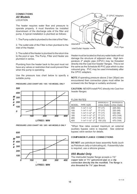
CONNECTIONSAll ModelsLOCATION2" CPVC AdaptersThe heater requires water flow and pressure tooperate properly. It must therefore be installeddownstream of the discharge side of the filter andpump. A typical installation is plumbed as follows:1. The Pump outlet is plumbed to the inlet of the Filter.2. The outlet side of the Filter is then plumbed to theinlet of the Heater.mbsmall.tifInlet/Outlet HeaderPVC PipeBMRA3. The outlet of the Heater is plumbed to the return lineto the pool or spa. The Pump, Filter and Heater areplumbed in series.Plumbing from the heater back to the pool must nothave any valves or restriction that could prevent flowwhen the pump is operating.Use the pressure loss chart below to specify asuitable pump.PRESSURE LOSS CHART 055 / 105 / 155 MODEL ONLY50040030020010000 100 200 300 400LITRES / MINHeater must be located so that any water leaks will notdamage the structure of adjacent area. High temperature2" plastic pipe (CPVC) may be threadeddirectly into the Cast Iron header flanges. This is notthe same as the Schedule 80 PVC pipe which is alsocoloured grey. PVC may be used immediately afterthe CPVC adapters.NOTE:If operating pressure above 2 bar (30psi) areencountered then connection pipes must either bescrewed into the flange or suitably anchored.CAUTION: NEVER install PVC directly into Cast Ironheader flanges.FLOW RATESMINIMUM/min. MAXIMUM/min.MODEL PIPE SIZE Litres (Gals) Litres (Gals)055 1-1/4"-1-1/2" 77 (17) 225 (50)105 1-1/4"-1-1/2" 77 (17) 220 (49)155 1-1/4"-1-1/2" -2" 77 (17) 430 (95)185 1-1/4"-1-1/2" -2" 77 (17) 470 (104)265 1-1/4"-1-1/2" -2" 95 (21) 470 (104)405 1-1/4"-1-1/2" -2" 150 (33) 470 (104)MBARPRESSURE LOSS CHART 185 / 265 / 405 MODELS ONLY6005004003002001000 100 200 300 400LITRES / MIN*When flow rates exceed maximum an externalauxiliary bypass valve is required. See externalbypass valve section for details.COMPANION FLANGE CONNECTIONSDO NOT use petroleum base assembly fluids (suchas Petroleum Jelly or lubricating oil). If assembly lubeis required, use a silicone grease.055 Model OnlyThe inlet/outlet header flange accepts a 1½"copperconnectiontubedirectlyor 1¼"intogalvanizedthe manifold.pipe asThea slipalso threaded for 1½" pipe thread.flange is1810-11-05
![314 MSDS - Swimfresh Calcium Hardness In[...]](https://img.yumpu.com/49910507/1/190x245/314-msds-swimfresh-calcium-hardness-in.jpg?quality=85)