SECTION 2 / INSTALLATIONINSTRUCTIONSIMPORTANT NOTICEThese instructions are intended for the use of qualifiedpersonnel only, specifically trained and experiencedin the installation of this type of heating equipmentand related system components. Installationand service personnel must be CORGI registered.Persons not qualified must not attempt to fix thisequipment nor attempt repairs according to theseinstructions.WARNING:Improper installation, adjustment, alteration, serviceor maintenance may damage the equipment, createa hazard resulting in asphyxiation, explosion or fire,and will void the warranty.STATUTORY REQUIREMENTSGas Regulations, Safety (Installation 1994 and Use)It is the law that all gas appliances are installed bycompetent persons in accordance with the aboveregulations. Failure to install appliances correctlycould lead to prosecution. It is in your own interest,and that of safety, to ensure that the law is compliedwith.General RequirementsThe appliance must be installed by a competentperson ie. CORGI registered in accordance with therelevant requirements of the Gas Safety Regulations,current I.E.E. Regulations, Model Water Byelaws,Local Water Authority Byelaws and any relevantrequirements of the local gas supplier, local authorityand the relevant British Standard Codes of practiceand Building Regulations. Manufacturers notes mustnot be taken in any way as overriding statutoryobligations. Typical documents include:Models 055, 105 & 155BS. 5440:1 Flues (for gas appliances of rated input notexceeding 60 KW).BS. 5440:2 Ventilation (for gas appliances of rated input notexceeding 60KW).BS. 5449 Forced circulation hot water systems.BS. 6798 Installation of gas fired hot water boilers ofrated input not exceeding 60 KW.BS. 6891: Installation of low pressure pipework.Health & Safety Document No. 635.The Electricity at Work regulations, 1989.CP341; Water Supply.British Gas Publications:IM2; Purging Procedures of Non-domestic Gas InstallationsIM5, Soundness Testing Procedures for Industrial andCommercial Gas Installations.8Models 185, 265 & 405BS. 6891; Installation of low pressure pipework.BS. 6644; Installation of Gas Fired Hot WaterBoilers 60kW to 2MW.CP 341; Water Supply.British Gas Publications:IM2; Purging Procedures on Non-domesticGas Installations.IM5; Soundness Testing Procedures forIndustrial and Commercial Gas Installations.IM11; Flues for Commercial and IndustrialGas Fired Boilers and Air <strong>Heaters</strong>.Model Water Byelaws.This appliance must be installed externally in open air(without a flue) or indoors (with a suitable flue system)in a room separated from living rooms and providedwith appropriate ventilation direct to the outside.The appliance must be used only in accordance withthese instructions. Incorrect use is dangerous andinvalidates all warranties and Certification.Conversion Instructions.The heater is supplied in two versions,one for usewith Natural Gas, G20 at 20 mbar inlet pressure, theother for Propane, G31 at 37 mbar. If it is necessaryto convert the heater for use on the other gas theappropriate conversion kit must be purchased andfitted using the instructions provided.NOTE: The heater should not be located in an areawhere possible water leakage will result in damageto the area adjacent to the appliance or to thestructure. When such locations cannot beavoided, it is recommended that a suitable drain pan,adequately drained, be installed under the appliance.The pan must not restrict combustion air flow.BASE INSTALLATIONHeater must be mounted on a level base, such ascement slab, cement blocks or other non-combustiblesurface. An alternative method for providing abase for combustible floors is illustrated below.<strong>Heaters</strong> must not be installed on carpeting.12" Min.300mmbase.tif4" Min.100mm12" Min.300mmSheet Metal24 Gauge0.7mmHollow concrete cinder block, align holes andleave ends open. Alternative method for providinga non-combustible base.01-10-98
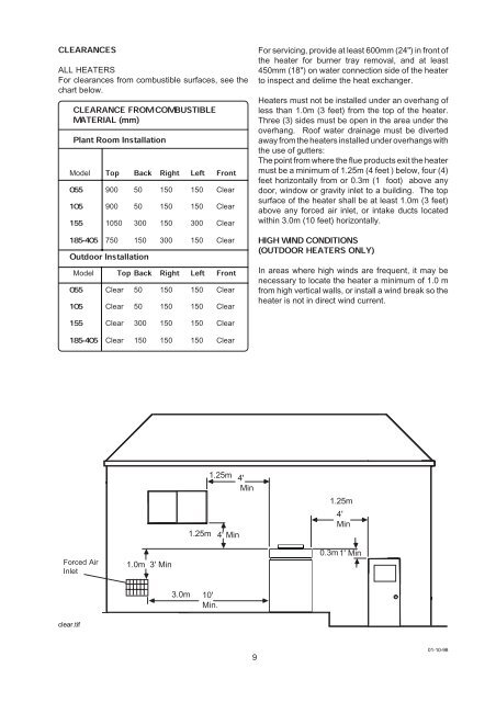
CLEARANCESALL HEATERSFor clearances from combustible surfaces, see thechart below.CLEARANCEMATERIAL (mm)FROM COMBUSTIBLEPlant Room InstallationTop Back Right Left FrontModel055 900 50 150 150 Clear105 900 50 150 150 Clear155 1050 300 150 300 Clear185-405 750 150 300 150 ClearOutdoor InstallationTop Back Right Left FrontModel055 Clear 50 150 150 Clear105 Clear 50 150 150 Clear155 Clear 300 150 150 Clear185-405 Clear 150 150 150 ClearFor servicing, provide at least 600mm (24") in front ofthe heater for burner tray removal, and at least450mm (18") on water connection side of the heaterto inspect and delime the heat exchanger.<strong>Heaters</strong> must not be installed under an overhang ofless than 1.0m (3 feet) from the top of the heater.Three (3) sides must be open in the area under theoverhang. Roof water drainage must be divertedaway from the heaters installed under overhangs withthe use of gutters:The point from where the flue products exit the heatermust be a minimum of 1.25m (4 feet ) below, four (4)feet horizontally from or 0.3m (1 foot) above anydoor, window or gravity inlet to a building. The topsurface of the heater shall be at least 1.0m (3 feet)above any forced air inlet, or intake ducts locatedwithin 3.0m (10 feet) horizontally.HIGH WIND CONDITIONS(OUTDOOR HEATERS ONLY)In areas where high winds are frequent, it may benecessary to locate the heater a minimum of 1.0 mfrom high vertical walls, or install a wind break so theheater is not in direct wind current.1.25m1.25m4' Min4'Min1.25m4'MinForced AirInlet1.0m 3' Min0.3m1' Min3.0m10'Min.clear.tif901-10-98


![314 MSDS - Swimfresh Calcium Hardness In[...]](https://img.yumpu.com/49910507/1/190x245/314-msds-swimfresh-calcium-hardness-in.jpg?quality=85)