Measuring Gas Velocity with the D-FL 100 Differential Pressure Bar
Measuring Gas Velocity with the D-FL 100 Differential Pressure Bar
Measuring Gas Velocity with the D-FL 100 Differential Pressure Bar
You also want an ePaper? Increase the reach of your titles
YUMPU automatically turns print PDFs into web optimized ePapers that Google loves.
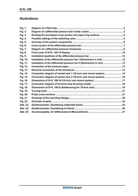
D-<strong>FL</strong> <strong>100</strong>IllustrationsFig. 1: Diagram of a Pitot tube .......................................................................................................2Fig. 2: Diagram of a differential pressure bar inside a stack......................................................3Fig. 3: Dividing <strong>the</strong> duct/stack cross section into equal ring surfaces .....................................4Fig. 4: Possible settings of <strong>the</strong> switching valve...........................................................................5Fig. 5: Overview of <strong>the</strong> system components ................................................................................6Fig. 6: Cross section of <strong>the</strong> differential pressure bar..................................................................7Fig. 7: Diagram of a differential pressure transducer..................................................................8Fig. 8: Front cover of D-<strong>FL</strong> <strong>100</strong>-10 Display .................................................................................10Fig. 9: Installation positions of <strong>the</strong> differential pressure bar ...................................................12Fig. 10: Installation of <strong>the</strong> differential pressure bar I (Dimensions in mm)...............................12Fig. 11: Installation of <strong>the</strong> differential pressure bar II (Dimensions in mm)..............................13Fig. 12: Connection of <strong>the</strong> pressure pipes ...................................................................................13Fig. 13: Electrical connection of <strong>the</strong> transducer ..........................................................................14Fig. 14: Connection diagram of socket rack 1 (19-inch rack mount system) ...........................15Fig. 15: Connection diagram of socket rack 2 (19-inch rack mount system) ...........................16Fig. 16: Dimensions of D-<strong>FL</strong> <strong>100</strong>-10 (19-inch rack mount system) ............................................17Fig. 17: Connection diagram of terminal strip (housing model) ................................................18Fig. 18: Dimensions of D-<strong>FL</strong> <strong>100</strong>-G (fieldhousing for 19-inch rack)...........................................19Fig. 19: Turning knob ......................................................................................................................21Fig. 20: Probe cross sections ........................................................................................................27Fig. 21: Drawings of <strong>the</strong> mounting flanges...................................................................................28Fig. 22: Overview of parts...............................................................................................................32Abb. 23: Gerätevarianten, Darstellung außerhalb Kamin .............................................................35Abb. 24: Gerätevarianten, Darstellung im Kamin ..........................................................................36Abb. 25: Anschlussplatte, für Differenzdruck-Messumformer.....................................................37GmbH


