

Measuring Gas Velocity with the D-FL 100 Differential Pressure Bar
Measuring Gas Velocity with the D-FL 100 Differential Pressure Bar
Measuring Gas Velocity with the D-FL 100 Differential Pressure Bar

You also want an ePaper? Increase the reach of your titles
YUMPU automatically turns print PDFs into web optimized ePapers that Google loves.
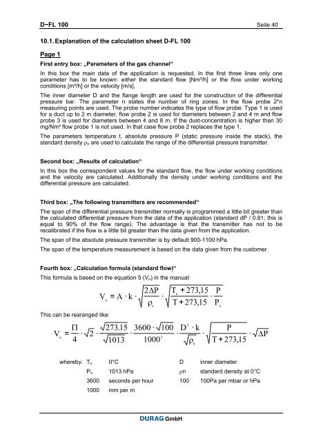
D−<strong>FL</strong> <strong>100</strong> Seite 4010.1. Explanation of <strong>the</strong> calculation sheet D-<strong>FL</strong> <strong>100</strong>Page 1First entry box: „Parameters of <strong>the</strong> gas channel“In this box <strong>the</strong> main data of <strong>the</strong> application is requested. In <strong>the</strong> first three lines only oneparameter has to be known: ei<strong>the</strong>r <strong>the</strong> standard flow [Nm³/h] or <strong>the</strong> flow under workingconditions [m³/h] or <strong>the</strong> velocity [m/s].The inner diameter D and <strong>the</strong> flange length are used for <strong>the</strong> construction of <strong>the</strong> differentialpressure bar. The parameter n states <strong>the</strong> number of ring zones. In <strong>the</strong> flow probe 2*nmeasuring points are used. The probe number indicates <strong>the</strong> type of flow probe: Type 1 is usedfor a duct up to 2 m diameter, flow probe 2 is used for diameters between 2 and 4 m and flowprobe 3 is used for diameters between 4 and 8 m. If <strong>the</strong> dust-concentration is higher than 30mg/Nm³ flow probe 1 is not used. In that case flow probe 2 replaces <strong>the</strong> type 1.The parameters temperature t, absolute pressure P (static pressure inside <strong>the</strong> stack), <strong>the</strong>standard density ρ n are used to calculate <strong>the</strong> range of <strong>the</strong> differential pressure transmitter.Second box: „Results of calculation“In this box <strong>the</strong> correspondent values for <strong>the</strong> standard flow, <strong>the</strong> flow under working conditionsand <strong>the</strong> velocity are calculated. Additionally <strong>the</strong> density under working conditions and <strong>the</strong>differential pressure are calculated.Third box: „The following transmitters are recommended“The span of <strong>the</strong> differential pressure transmitter normally is programmed a little bit greater than<strong>the</strong> calculated differential pressure from <strong>the</strong> data of <strong>the</strong> application (standard dP / 0.81; this isequal to 90% of <strong>the</strong> flow range). The advantage is that <strong>the</strong> transmitter has not to berecalibrated if <strong>the</strong> flow is a little bit greater than <strong>the</strong> data given from <strong>the</strong> application.The span of <strong>the</strong> absolute pressure transmitter is by default 900-1<strong>100</strong> hPa.The span of <strong>the</strong> temperature measurement is based on <strong>the</strong> data given from <strong>the</strong> customer.Fourth box: „Calculation formula (standard flow)“This formula is based on <strong>the</strong> equation 5 (V n ) in <strong>the</strong> manual:VThis can be rearanged like:Vn2ΔP T + 273,15 Pn= A· k · ··ρ T+27315 , PΠ 273.15 3600 · <strong>100</strong>= · 2 · ·4 1013 <strong>100</strong>0n 2n2D · k P· ·ρ T + 273,15nn·ΔPwhereby: T n 0°C D inner diameterP n 1013 hPa ρn standard density at 0°C3600 seconds per hour <strong>100</strong> <strong>100</strong>Pa per mbar or hPa<strong>100</strong>0 mm per mGmbH


