

AN369: Si4010 Antenna Interface and Matching Network ... - wless.ru
AN369: Si4010 Antenna Interface and Matching Network ... - wless.ru
AN369: Si4010 Antenna Interface and Matching Network ... - wless.ru

Create successful ePaper yourself
Turn your PDF publications into a flip-book with our unique Google optimized e-Paper software.
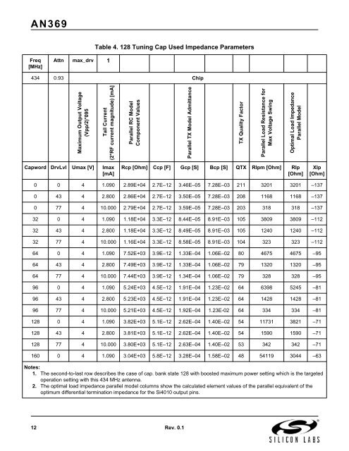
<strong>AN369</strong>Table 4. 128 Tuning Cap Used Impedance ParametersFreq[MHz]Attn max_drv 1434 0.93 ChipMaximum Output Voltage(Vpp/2)*095Tail Current(2*RF current magnitude) [mA]Parallel RC ModelComponent ValuesParallel TX Model AdmittanceTX Quality FactorParallel Load Resistance forMax Voltage SwingOptimal Load ImpedanceParallel ModelCapword DrvLvl Umax [V] Imax[mA]Rcp [Ohm] Ccp [F] Gcp [S] Bcp [S] QTX Rlpm [Ohm] Rlp[Ohm]Xlp[Ohm]0 0 4 1.090 2.89E+04 2.7E–12 3.46E–05 7.28E–03 211 3201 3201 –1370 43 4 2.800 2.86E+04 2.7E–12 3.50E–05 7.28E–03 208 1168 1168 –1370 77 4 10.000 2.79E+04 2.7E–12 3.59E–05 7.28E–03 203 318 318 –13732 0 4 1.090 1.18E+04 3.3E–12 8.44E–05 8.91E–03 105 3809 3809 –11232 43 4 2.800 1.18E+04 3.3E–12 8.49E–05 8.91E–03 105 1240 1240 –11232 77 4 10.000 1.16E+04 3.3E–12 8.58E–05 8.91E–03 104 323 323 –11264 0 4 1.090 7.52E+03 3.9E–12 1.33E–04 1.06E–02 80 4675 4675 –9564 43 4 2.800 7.49E+03 3.9E–12 1.33E–04 1.06E–02 79 1320 1320 –9564 77 4 10.000 7.44E+03 3.9E–12 1.34E–04 1.06E–02 79 328 328 –9596 0 4 1.090 5.24E+03 4.5E–12 1.91E–04 1.23E–02 64 6398 5245 –8196 43 4 2.800 5.23E+03 4.5E–12 1.91E–04 1.23E–02 64 1428 1428 –8196 77 4 10.000 5.21E+03 4.5E–12 1.92E–04 1.23E-02 64 334 334 –81128 0 4 1.090 3.82E+03 5.1E–12 2.62E–04 1.40E–02 54 11731 3821 –71128 43 4 2.800 3.81E+03 5.1E–12 2.62E–04 1.40E–02 54 1590 1590 –71128 77 4 10.000 3.80E+03 5.1E–12 2.63E–04 1.40E–02 53 342 342 –71160 0 4 1.090 3.04E+03 5.8E–12 3.28E–04 1.58E–02 48 54119 3044 –63Notes:1. The second-to-last row describes the case of cap. bank state 128 with boosted maximum power setting which is the targetedoperation setting with this 434 MHz antenna.2. The optimal load impedance parallel model columns show the calculated element values of the parallel equivalent of theoptimum differential termination impedance for the <strong>Si4010</strong> output pins.12 Rev. 0.1


