

AN369: Si4010 Antenna Interface and Matching Network ... - wless.ru
AN369: Si4010 Antenna Interface and Matching Network ... - wless.ru
AN369: Si4010 Antenna Interface and Matching Network ... - wless.ru

Create successful ePaper yourself
Turn your PDF publications into a flip-book with our unique Google optimized e-Paper software.
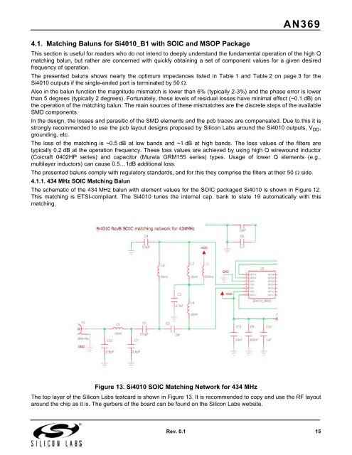
<strong>AN369</strong>4.1. <strong>Matching</strong> Baluns for <strong>Si4010</strong>_B1 with SOIC <strong>and</strong> MSOP PackageThis section is useful for readers who do not intend to deeply underst<strong>and</strong> the fundamental operation of the high Qmatching balun, but rather are concerned with quickly obtaining a set of component values for a given desiredfrequency of operation.The presented baluns shows nearly the optimum impedances listed in Table 1 <strong>and</strong> Table 2 on page 3 for the<strong>Si4010</strong> outputs if the single-ended port is terminated by 50 .Also in the balun function the magnitude mismatch is lower than 6% (typically 2-3%) <strong>and</strong> the phase error is lowerthan 5 degrees (typically 2 degrees). Fortunately, these levels of residual losses have minimal effect (~0.1 dB) onthe operation of the matching balun. The main sources of these mismatches are the discrete steps of the availableSMD components.In the design, the losses <strong>and</strong> parasitic of the SMD elements <strong>and</strong> the pcb traces are compensated. Due to this it isstrongly recommended to use the pcb layout designs proposed by Silicon Labs around the <strong>Si4010</strong> outputs, V DD ,grounding, etc.The loss of the matching is ~0.5 dB at low b<strong>and</strong>s <strong>and</strong> ~1 dB at high b<strong>and</strong>s. The loss values of the filters aretypically 0.2 dB at the operation frequency. These loss values are achieved by using high Q wirewound inductor(Coicraft 0402HP series) <strong>and</strong> capacitor (Murata GRM155 series) types. Usage of lower Q elements (e.g.,multilayer inductors) can cause 0.5…1dB additional loss.The presented baluns comply with regulatory st<strong>and</strong>ards, <strong>and</strong> for this they comprise the filters at their 50 side.4.1.1. 434 MHz SOIC <strong>Matching</strong> BalunThe schematic of the 434 MHz balun with element values for the SOIC packaged <strong>Si4010</strong> is shown in Figure 12.This matching is ETSI-compliant. The <strong>Si4010</strong> tunes the internal cap. bank to state 19 automatically with thismatching.Figure 13. <strong>Si4010</strong> SOIC <strong>Matching</strong> <strong>Network</strong> for 434 MHzThe top layer of the Silicon Labs testcard is shown in Figure 13. It is recommended to copy <strong>and</strong> use the RF layoutaround the chip as it is. The gerbers of the board can be found on the Silicon Labs website.Rev. 0.1 15


