

AN369: Si4010 Antenna Interface and Matching Network ... - wless.ru
AN369: Si4010 Antenna Interface and Matching Network ... - wless.ru
AN369: Si4010 Antenna Interface and Matching Network ... - wless.ru

You also want an ePaper? Increase the reach of your titles
YUMPU automatically turns print PDFs into web optimized ePapers that Google loves.
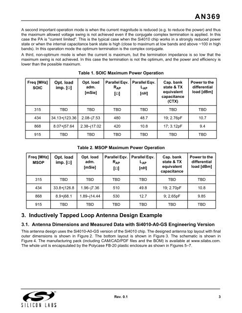
<strong>AN369</strong>A second important operation mode is when the current magnitude is reduced (e.g. to reduce the power) <strong>and</strong> thusthe maximum allowed voltage swing is not achieved even if the conjugate complex termination is applied. In thiscase the PA is "current limited". This is the typical case when the <strong>Si4010</strong> chip works in a strongly reduced powerstate or when the internal capacitance bank state is high (close to maximum at low b<strong>and</strong>s <strong>and</strong> above ~100 in highb<strong>and</strong>s). In this operation mode the optimum termination is the complex conjugate.A third, non-optimum mode is when the current is maximum, but the termination impedance is so low that themaximum swing is not achieved. In this case the termination is not the optimum, <strong>and</strong> the power <strong>and</strong> efficiency islower than the possible maximum.Table 1. SOIC Maximum Power OperationFreq [MHz]SOICOpt. loadimp. []Opt. loadadm.[mSie]Parallel Eqv.R AP[]Parallel Eqv.L AP[nH]Cap. bankstate & TXequivalentcapacitance(CTX)Power to thedifferentialload [dBm]315 TBD TBD TBD TBD TBD TBD434 34.13+j123.36 2.08–j7.53 480 48.7 19; 2.76pF 10.7868 8.07+j57.64 2.38–j17.02 420 10.8 17; 3.12pF 9.4915 TBD TBD TBD TBD TBD TBDTable 2. MSOP Maximum Power OperationFreq [MHz]MSOPOpt. loadimp. []Opt. loadadm.[mSie]Parallel Eqv.R AP[]Parallel Eqv.L AP[nH]Cap. bankstate & TXequivalentcapacitancePower to thedifferentialload [dBm]315 TBD TBD TBD TBD TBD TBD434 33.8+j126.8 1.96–j7.36 510 49.8 19; 2.70pF 10.8868 8.9+j68.1 1.89–j14.44 530 12.7 9; 2.65pF 9.85915 TBD TBD TBD TBD TBD TBD3. Inductively Tapped Loop <strong>Antenna</strong> Design Example3.1. <strong>Antenna</strong> Dimensions <strong>and</strong> Measured Data with <strong>Si4010</strong>-A0-GS Engineering VersionThis antenna design uses the <strong>Si4010</strong>-A0-GS version of the <strong>Si4010</strong> chip. The designed antenna top layout with finalouter dimensions is shown in Figure 2. The bottom layout is shown in Figure 3. The schematic is shown inFigure 4. The manufacturing pack (including CAM/CAD/PDF files <strong>and</strong> the BOM) is available at www.silabs.com.The whole unit is encapsulated by the Polycase FB-20 plastic enclosure as shown in Figures 5–7.Rev. 0.1 3


