Design and Implementation of a Pillbox Antenna for an Airborne ...
Design and Implementation of a Pillbox Antenna for an Airborne ...
Design and Implementation of a Pillbox Antenna for an Airborne ...

You also want an ePaper? Increase the reach of your titles
YUMPU automatically turns print PDFs into web optimized ePapers that Google loves.
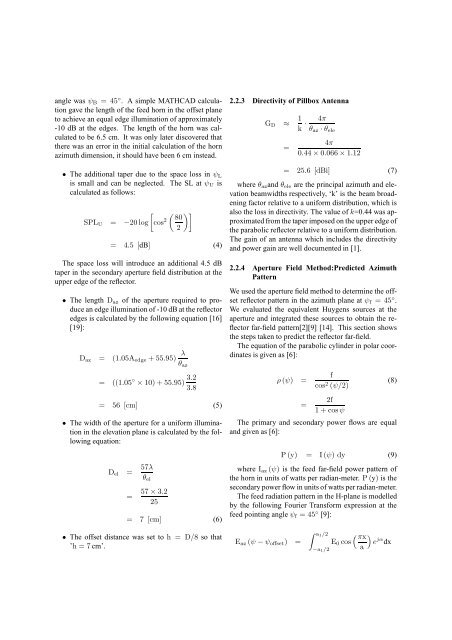
<strong>an</strong>gle was ψ B = 45 ◦ . A simple MATHCAD calculationgave the length <strong>of</strong> the feed horn in the <strong>of</strong>fset pl<strong>an</strong>eto achieve <strong>an</strong> equal edge illumination <strong>of</strong> approximately-10 dB at the edges. The length <strong>of</strong> the horn was calculatedto be 6.5 cm. It was only later discovered thatthere was <strong>an</strong> error in the initial calculation <strong>of</strong> the hornazimuth dimension, it should have been 6 cm instead.• The additional taper due to the space loss in ψ Lis small <strong><strong>an</strong>d</strong> c<strong>an</strong> be neglected. The SL at ψ U iscalculated as follows:[ ( )] 80SPL U = −20 log cos 2 2= 4.5 [dB] (4)The space loss will introduce <strong>an</strong> additional 4.5 dBtaper in the secondary aperture field distribution at theupper edge <strong>of</strong> the reflector.• The length D az <strong>of</strong> the aperture required to produce<strong>an</strong> edge illumination <strong>of</strong> -10 dB at the reflectoredges is calculated by the following equation [16][19]:D az = (1.05A edge + 55.95) λθ az= ((1.05 ◦ × 10) + 55.95) 3.23.8= 56 [cm] (5)• The width <strong>of</strong> the aperture <strong>for</strong> a uni<strong>for</strong>m illuminationin the elevation pl<strong>an</strong>e is calculated by the followingequation:D el = 57λθ el=57 × 3.225= 7 [cm] (6)• The <strong>of</strong>fset dist<strong>an</strong>ce was set to h = D/8 so that’h = 7 cm’.2.2.3 Directivity <strong>of</strong> <strong>Pillbox</strong> <strong>Antenna</strong>G D ≈ 1 k · 4πθ az · θ ele=4π0.44 × 0.066 × 1.12= 25.6 [dBi] (7)where θ az <strong><strong>an</strong>d</strong> θ ele are the principal azimuth <strong><strong>an</strong>d</strong> elevationbeamwidths respectively, ‘k’ is the beam broadeningfactor relative to a uni<strong>for</strong>m distribution, which isalso the loss in directivity. The value <strong>of</strong> k=0.44 was approximatedfrom the taper imposed on the upper edge <strong>of</strong>the parabolic reflector relative to a uni<strong>for</strong>m distribution.The gain <strong>of</strong> <strong>an</strong> <strong>an</strong>tenna which includes the directivity<strong><strong>an</strong>d</strong> power gain are well documented in [1].2.2.4 Aperture Field Method:Predicted AzimuthPatternWe used the aperture field method to determine the <strong>of</strong>fsetreflector pattern in the azimuth pl<strong>an</strong>e at ψ f = 45 ◦ .We evaluated the equivalent Huygens sources at theaperture <strong><strong>an</strong>d</strong> integrated these sources to obtain the reflectorfar-field pattern[2][9] [14]. This section showsthe steps taken to predict the reflector far-field.The equation <strong>of</strong> the parabolic cylinder in polar coordinatesis given as [6]:ρ (ψ) ==fcos 2 (ψ/2)2f1 + cosψ(8)The primary <strong><strong>an</strong>d</strong> secondary power flows are equal<strong><strong>an</strong>d</strong> given as [6]:P (y) = I (ψ) dy (9)where I az (ψ) is the feed far-field power pattern <strong>of</strong>the horn in units <strong>of</strong> watts per radi<strong>an</strong>-meter. P (y) is thesecondary power flow in units <strong>of</strong> watts per radi<strong>an</strong>-meter.The feed radiation pattern in the H-pl<strong>an</strong>e is modelledby the following Fourier Tr<strong>an</strong>s<strong>for</strong>m expression at thefeed pointing <strong>an</strong>gle ψ f = 45 ◦ [9]:E az (ψ − ψ <strong>of</strong>fset ) =∫ a1/2−a 1/2E 0 cos( πx)e jα dxa