the development of a node for a hardware reconfigurable parallel ...
the development of a node for a hardware reconfigurable parallel ...
the development of a node for a hardware reconfigurable parallel ...

You also want an ePaper? Increase the reach of your titles
YUMPU automatically turns print PDFs into web optimized ePapers that Google loves.
THE DEVELOPMENT OF A NODE FOR AHARDWARE RECONFIGURABLEPARALLEL PROCESSORprepared byCarl Frans van SchaikA dissertation submitted to <strong>the</strong> Department <strong>of</strong> Electrical Engineering,University <strong>of</strong> Cape Townin partial fulfilment <strong>of</strong> <strong>the</strong> requirements, <strong>for</strong> <strong>the</strong> degree <strong>of</strong> Master <strong>of</strong>Science in EngineeringCape Town, January 2002Last edit: Tue, 29 Jan 2002 8:55
DeclarationI, Carl Frans van Schaik declair that all in<strong>for</strong>mation contained within this dissertationreport is original and my own work to <strong>the</strong> best <strong>of</strong> my knowledge, except were indicatedin <strong>the</strong> text. This dissertation report has not been submitted, in whole or part toany organisation o<strong>the</strong>r than those directly related to <strong>the</strong> University <strong>of</strong> Cape Town.signedCarl Frans van SchaikDateiii
AcknowledgementsI would like to thank all <strong>the</strong> people <strong>for</strong> assisting in <strong>the</strong> completion <strong>of</strong> this project aswell as:My supervisor Pr<strong>of</strong>essor M.R. Inggs <strong>for</strong> his time, dedication and supporting <strong>of</strong> thisproject.Alan Langman <strong>for</strong> being my ’un<strong>of</strong>ficial’ supervisor and who provided much inputand focus <strong>for</strong> <strong>the</strong> project not to mention a lot <strong>of</strong> patience.v
AbstractThis dissertation concerns <strong>the</strong> design and implementation <strong>of</strong> a <strong>node</strong> <strong>for</strong> a <strong>hardware</strong><strong>reconfigurable</strong> <strong>parallel</strong> processor. The <strong>hardware</strong> that was developed allows <strong>for</strong> <strong>the</strong>fur<strong>the</strong>r <strong>development</strong> <strong>of</strong> a <strong>parallel</strong> processor with configurable <strong>hardware</strong> acceleration.Each <strong>node</strong> in <strong>the</strong> system has a standard microprocessor and <strong>reconfigurable</strong> logic deviceand has high speed communications channels <strong>for</strong> inter-<strong>node</strong> communication.The design <strong>of</strong> <strong>the</strong> <strong>node</strong> provided high speed serial communications channels allowing<strong>the</strong> implementation <strong>of</strong> various network topographies. The <strong>node</strong> also provided a PCImaster interface to provide an external interface and communicate with local <strong>node</strong>s on<strong>the</strong> bus. A high speed RISC processor provided communications and system controlfunctions and <strong>the</strong> <strong>reconfigurable</strong> logic device provided communication interfaces anddata processing functions.The <strong>node</strong> was designed and implemented as a PCI card that interfaced a standardPCI bus. VHDL designs <strong>for</strong> logic devices that provided system support weredeveloped, VHDL designs <strong>for</strong> <strong>the</strong> <strong>reconfigurable</strong> logic FPGA and s<strong>of</strong>tware includingdrivers and system s<strong>of</strong>tware were written <strong>for</strong> <strong>the</strong> <strong>node</strong>. The 64-bit version Linux operatingsystem was <strong>the</strong>n ported to <strong>the</strong> processor providing a UNIX environment <strong>for</strong> <strong>the</strong>system.The <strong>node</strong> functioned as specified and <strong>parallel</strong> and <strong>hardware</strong> accelerated processingwas demonstrated. The <strong>hardware</strong> acceleration was shown to provide substantialper<strong>for</strong>mance benefits <strong>for</strong> <strong>the</strong> system.vii
ContentsAcknowelgementsAbstractGlossaryvviixvii1 Introduction 11.1 Project Objectives . . . . . . . . . . . . . . . . . . . . . . . . . . . . 21.2 Outline <strong>of</strong> Dissertation . . . . . . . . . . . . . . . . . . . . . . . . . 32 Theoretical Background 52.1 Parallel Computing . . . . . . . . . . . . . . . . . . . . . . . . . . . 52.1.1 Introduction to Parallel Processing . . . . . . . . . . . . . . . 52.1.2 Parallel S<strong>of</strong>tware . . . . . . . . . . . . . . . . . . . . . . . . 62.1.3 Hardware Configurable Parallel Processors . . . . . . . . . . 62.1.4 Communication Architectures . . . . . . . . . . . . . . . . . 72.2 Example Parallel Processors . . . . . . . . . . . . . . . . . . . . . . 82.3 Example Reconfigurable Processors . . . . . . . . . . . . . . . . . . 112.4 Reconfigurable Logic . . . . . . . . . . . . . . . . . . . . . . . . . . 113 User Requirements and Specification 133.1 User Requirements . . . . . . . . . . . . . . . . . . . . . . . . . . . 133.2 Project Deliverables . . . . . . . . . . . . . . . . . . . . . . . . . . . 143.3 Requirements Analysis . . . . . . . . . . . . . . . . . . . . . . . . . 143.3.1 Silicon requirements . . . . . . . . . . . . . . . . . . . . . . 143.3.2 Mechanical requirements . . . . . . . . . . . . . . . . . . . . 163.3.3 Interface requirements . . . . . . . . . . . . . . . . . . . . . 163.3.4 VHDL / Macro-function requirements . . . . . . . . . . . . . 163.3.5 S<strong>of</strong>tware requirements . . . . . . . . . . . . . . . . . . . . . 173.4 System Specifications . . . . . . . . . . . . . . . . . . . . . . . . . . 173.4.1 Processing Algorithms . . . . . . . . . . . . . . . . . . . . . 173.4.2 Communications . . . . . . . . . . . . . . . . . . . . . . . . 183.5 Test Specifications . . . . . . . . . . . . . . . . . . . . . . . . . . . 18ix
CONTENTS4 Concept Study 194.1 Parallel <strong>node</strong> requirements . . . . . . . . . . . . . . . . . . . . . . . 194.2 Processor requirements . . . . . . . . . . . . . . . . . . . . . . . . . 204.2.1 System Requirements . . . . . . . . . . . . . . . . . . . . . 214.2.2 Processor Selection . . . . . . . . . . . . . . . . . . . . . . . 214.3 Reconfigurable logic requirements . . . . . . . . . . . . . . . . . . . 224.4 High level system design . . . . . . . . . . . . . . . . . . . . . . . . 234.5 Communication infrastructure choices . . . . . . . . . . . . . . . . . 244.6 S<strong>of</strong>tware requirements . . . . . . . . . . . . . . . . . . . . . . . . . 255 Hardware Design and Implementation 275.1 Processing Node Components . . . . . . . . . . . . . . . . . . . . . 275.2 Design Choices . . . . . . . . . . . . . . . . . . . . . . . . . . . . . 285.2.1 Choice A . . . . . . . . . . . . . . . . . . . . . . . . . . . . 285.2.2 Choice B . . . . . . . . . . . . . . . . . . . . . . . . . . . . 305.2.3 Choice C . . . . . . . . . . . . . . . . . . . . . . . . . . . . 325.3 High Level System Design . . . . . . . . . . . . . . . . . . . . . . . 325.4 Functional Unit Design . . . . . . . . . . . . . . . . . . . . . . . . . 355.4.1 Microprocessor . . . . . . . . . . . . . . . . . . . . . . . . . 355.4.2 Memory Controller . . . . . . . . . . . . . . . . . . . . . . . 375.4.3 Bus CPLD and Peripheral Bus . . . . . . . . . . . . . . . . . 395.4.4 FPGA . . . . . . . . . . . . . . . . . . . . . . . . . . . . . . 395.4.5 Clocking . . . . . . . . . . . . . . . . . . . . . . . . . . . . 405.4.6 Power and Peripheral Devices . . . . . . . . . . . . . . . . . 415.5 System Configuration Options . . . . . . . . . . . . . . . . . . . . . 425.6 Printed Circuit Board Design . . . . . . . . . . . . . . . . . . . . . . 425.7 Conclusion . . . . . . . . . . . . . . . . . . . . . . . . . . . . . . . 456 Hardware Verification 496.1 PCB Inspection . . . . . . . . . . . . . . . . . . . . . . . . . . . . . 496.2 Power Supply . . . . . . . . . . . . . . . . . . . . . . . . . . . . . . 496.3 Configurable Logic . . . . . . . . . . . . . . . . . . . . . . . . . . . 506.4 Memory Controller . . . . . . . . . . . . . . . . . . . . . . . . . . . 516.5 Processor . . . . . . . . . . . . . . . . . . . . . . . . . . . . . . . . 537 Firmware Implementation 557.1 VHDL design implications . . . . . . . . . . . . . . . . . . . . . . . 557.2 Configuration CPLD . . . . . . . . . . . . . . . . . . . . . . . . . . 567.2.1 Requirements . . . . . . . . . . . . . . . . . . . . . . . . . . 577.2.2 Specification and Design . . . . . . . . . . . . . . . . . . . . 587.2.3 Implementation . . . . . . . . . . . . . . . . . . . . . . . . . 597.3 Bus + Control CPLD . . . . . . . . . . . . . . . . . . . . . . . . . . 597.3.1 Requirements . . . . . . . . . . . . . . . . . . . . . . . . . . 59
CONTENTS7.3.2 Specification and Design . . . . . . . . . . . . . . . . . . . . 617.3.3 Implementation . . . . . . . . . . . . . . . . . . . . . . . . . 617.4 FPGA Designs . . . . . . . . . . . . . . . . . . . . . . . . . . . . . 627.4.1 Basic LED Test . . . . . . . . . . . . . . . . . . . . . . . . . 627.4.2 LVDS VHDL Test . . . . . . . . . . . . . . . . . . . . . . . 637.4.3 LVDS Schematic Test . . . . . . . . . . . . . . . . . . . . . 647.4.4 Local Bus Emulation Test . . . . . . . . . . . . . . . . . . . 657.4.5 16550 Compatible UART . . . . . . . . . . . . . . . . . . . 657.4.6 Remote Bus Access . . . . . . . . . . . . . . . . . . . . . . . 667.4.7 Local-Bus Test . . . . . . . . . . . . . . . . . . . . . . . . . 687.4.8 Sigma-Delta Modulator . . . . . . . . . . . . . . . . . . . . 687.4.9 Propane UART . . . . . . . . . . . . . . . . . . . . . . . . . 697.4.10 Propane Design . . . . . . . . . . . . . . . . . . . . . . . . . 697.4.11 DSP Experiment . . . . . . . . . . . . . . . . . . . . . . . . 747.5 Conclusions . . . . . . . . . . . . . . . . . . . . . . . . . . . . . . . 748 S<strong>of</strong>tware Development 758.1 Linux PC S<strong>of</strong>tware . . . . . . . . . . . . . . . . . . . . . . . . . . . 758.1.1 PCI Driver . . . . . . . . . . . . . . . . . . . . . . . . . . . 758.1.2 Bus Access and FLASH programmer . . . . . . . . . . . . . 788.1.3 Debugging and Utilities . . . . . . . . . . . . . . . . . . . . 798.2 MIPS S<strong>of</strong>tware . . . . . . . . . . . . . . . . . . . . . . . . . . . . . 808.2.1 Verification Programs . . . . . . . . . . . . . . . . . . . . . . 818.2.2 Diesel Boot-Loader . . . . . . . . . . . . . . . . . . . . . . . 818.2.3 Linux Kernel . . . . . . . . . . . . . . . . . . . . . . . . . . 828.2.4 Linux Programs . . . . . . . . . . . . . . . . . . . . . . . . . 879 Testing and Verification 899.1 Firmware Verification . . . . . . . . . . . . . . . . . . . . . . . . . . 899.1.1 Config CPLD . . . . . . . . . . . . . . . . . . . . . . . . . . 899.1.2 Bus + Control CPLD . . . . . . . . . . . . . . . . . . . . . . 909.1.3 FPGA Testing . . . . . . . . . . . . . . . . . . . . . . . . . . 909.2 S<strong>of</strong>tware Testing . . . . . . . . . . . . . . . . . . . . . . . . . . . . 929.3 Benchmarks . . . . . . . . . . . . . . . . . . . . . . . . . . . . . . . 9210 Conclusions and Future Work 9510.1 Conclusions . . . . . . . . . . . . . . . . . . . . . . . . . . . . . . . 9510.2 Future Work . . . . . . . . . . . . . . . . . . . . . . . . . . . . . . . 96Bibliography 99A Schematics and PCB 101B Oscilloscope Traces 119
CONTENTSC Source Code and Datasheets 123
List <strong>of</strong> Figures3.1 Basic Component Requirements <strong>of</strong> a Node . . . . . . . . . . . . . . . 153.2 Node interface requirements . . . . . . . . . . . . . . . . . . . . . . 175.1 Design architecture choice A . . . . . . . . . . . . . . . . . . . . . . 295.2 Design architecture choice B . . . . . . . . . . . . . . . . . . . . . . 315.3 Design architecture choice C . . . . . . . . . . . . . . . . . . . . . . 335.4 RC64574 Functional Block Diagram . . . . . . . . . . . . . . . . . . 365.5 RC64574 Interfaces . . . . . . . . . . . . . . . . . . . . . . . . . . . 375.6 GT64115 Interfaces . . . . . . . . . . . . . . . . . . . . . . . . . . . 385.7 Local and Peripheral Bus Configuration . . . . . . . . . . . . . . . . 395.8 Clock Distribution Architecture . . . . . . . . . . . . . . . . . . . . 415.9 Top side, unpopulated project <strong>hardware</strong> . . . . . . . . . . . . . . . . 455.10 Bottom side, unpopulated project <strong>hardware</strong> . . . . . . . . . . . . . . 465.11 Top side view, populated project <strong>hardware</strong> . . . . . . . . . . . . . . . 477.1 Data-Strobe Encoding . . . . . . . . . . . . . . . . . . . . . . . . . . 637.2 LVDS Transmitter Logic . . . . . . . . . . . . . . . . . . . . . . . . 647.3 High level overview <strong>of</strong> Remote Bus Access system . . . . . . . . . . 679.1 Normalised FFTW per<strong>for</strong>mance . . . . . . . . . . . . . . . . . . . . 94B.1 4X Clock Generation . . . . . . . . . . . . . . . . . . . . . . . . . . 120B.2 4X Clock - dV/dt (1GV/s per division) . . . . . . . . . . . . . . . . . 120B.3 LVDS Clock - FFT (266MHz) . . . . . . . . . . . . . . . . . . . . . 120B.4 LVDS Cable Delay and Signal Quality . . . . . . . . . . . . . . . . . 121B.5 LVDS Difference Voltage . . . . . . . . . . . . . . . . . . . . . . . . 121xiii
LIST OF FIGURES
List <strong>of</strong> Tables5.1 Memory device assignments . . . . . . . . . . . . . . . . . . . . . . 385.2 Worst case power supply calculations . . . . . . . . . . . . . . . . . 425.3 Galileo GT64115 Configuration . . . . . . . . . . . . . . . . . . . . 435.4 Interrupt and o<strong>the</strong>r Configuration . . . . . . . . . . . . . . . . . . . . 437.1 System control interface, on Chip Select 3 (CS3) . . . . . . . . . . . 628.1 Virtual Interrupt Allocation . . . . . . . . . . . . . . . . . . . . . . . 849.1 Benchmark Results . . . . . . . . . . . . . . . . . . . . . . . . . . . 93xv
LIST OF TABLES
GlossaryASIC Application Specific Integrated Circuit: An integrated circuit that has been speciallydesigned <strong>for</strong> a custom design, typically proprietary.CPLD Complex Programmable Logic Device: A programmable logic device similarto, but providing more features, such as flip-flops and feedback, than PALs andGALs.DCT Discrete Cosine Trans<strong>for</strong>m: A ma<strong>the</strong>matical algorithm to calculate <strong>the</strong> Cosinefunction components <strong>of</strong> a signal represented by a discrete set <strong>of</strong> points.FFT Fast Fourier Trans<strong>for</strong>m: A ma<strong>the</strong>matical algorithm <strong>for</strong> converting time domaindata into frequency domain data.FPGA Field Programmable Gate Array: A device providing a large array <strong>of</strong> configurablelogic building blocks and configurable routing interconnects <strong>for</strong> implementinglogic designs.PVM Parallel Virtual Machine: A s<strong>of</strong>tware library and application <strong>for</strong> running <strong>parallel</strong>processing programs on a heterogeneous network <strong>of</strong> machines.xvii
Chapter 1IntroductionThe goal <strong>of</strong> this MSc project was <strong>the</strong> design, implementation and testing <strong>of</strong> a <strong>node</strong> <strong>for</strong>a run-time <strong>hardware</strong> <strong>reconfigurable</strong> <strong>parallel</strong> computing processor. Three major taskswere undertaken in <strong>the</strong> completion <strong>of</strong> this project: Analysing a selection <strong>of</strong> successful<strong>parallel</strong> computing architectures and evaluating <strong>the</strong>ir characteristics. Specifying, designingand implementing <strong>the</strong> <strong>node</strong> <strong>hardware</strong> according to an architecture derived from<strong>the</strong> first task with <strong>the</strong> added advantage <strong>of</strong> configurable logic. And lastly, implementinga s<strong>of</strong>tware environment to provide a base <strong>for</strong> fur<strong>the</strong>r <strong>parallel</strong> processing research anddemonstrating basic pro<strong>of</strong>-<strong>of</strong>-concept examples.Configurable logic allows <strong>the</strong> logical circuitry <strong>of</strong> a specialised silicon chip, in particularFPGA’s, to be configured and changed without modifying <strong>the</strong> physical devicesin <strong>the</strong> system. FPGA devices allow <strong>for</strong> highly specialised digital designs to be implementedin general purpose silicon without <strong>the</strong> cost <strong>of</strong> developing custom silicon.Reconfigurable logic allows <strong>the</strong> logic design configured in <strong>the</strong> device to be changed atany time, especially while <strong>the</strong> device and system are in operation.Parallel processing is <strong>the</strong> use <strong>of</strong> multiple processing units connected toge<strong>the</strong>r tohandle an intensive computational task. Parallel processing is most commonly employedto reduce <strong>the</strong> processing time <strong>for</strong> certain very large or complicated processingtasks. This works because certain processing tasks can be achieved by allowing eachprocessing <strong>node</strong> to work on a subset <strong>of</strong> <strong>the</strong> entire problem. Some example applicationsin which <strong>parallel</strong> processing is used are: Image processing, finite element simulationsand computer generated animation.In many processing tasks, a single or small number <strong>of</strong> algorithmic functions areused extensively on a large amount <strong>of</strong> data. In certain cases, <strong>the</strong> algorithm used canbe implemented directly in a digital logic design in <strong>hardware</strong>. When this is possible,<strong>the</strong> <strong>hardware</strong> implementations are usually orders <strong>of</strong> magnitude faster than <strong>the</strong> samealgorithm running on a digital microprocessor. The possibility exists to implement<strong>the</strong>se <strong>hardware</strong> implementations in <strong>reconfigurable</strong> logic devices ra<strong>the</strong>r than customsilicon. The use <strong>of</strong> <strong>the</strong>se devices with <strong>the</strong>ir ability to implement arbitrary configurationsallows <strong>for</strong> a more general purpose <strong>hardware</strong> accelerated processing unit to bedesigned. Fur<strong>the</strong>r, by using <strong>the</strong>se <strong>hardware</strong> accelerated processing functions in com-1
1.1. PROJECT OBJECTIVESbination with standard microprocessors, a general purpose computing plat<strong>for</strong>m can bedesigned. Extending this idea with <strong>the</strong> principles <strong>of</strong> <strong>parallel</strong> processing, a <strong>hardware</strong>accelerated <strong>parallel</strong> processor can be designed which can greatly improve on <strong>the</strong> processingspeed <strong>of</strong> standard <strong>parallel</strong> processors. This is especially relevant <strong>for</strong> tasks thatemploy <strong>hardware</strong> implementable processing algorithms.The Radar Remote Sensing Group at <strong>the</strong> University <strong>of</strong> Cape Town has been usingCommercial Off The Shelf (COTS) machines <strong>for</strong> <strong>parallel</strong> processing. The GOLACHprocessor is a network <strong>of</strong> standard Pentium II machines running <strong>the</strong> Beowulf <strong>parallel</strong>processing s<strong>of</strong>tware. The <strong>parallel</strong> processor is used primarily <strong>for</strong> <strong>the</strong> processing <strong>of</strong> datafrom various radar projects. Various MSc projects have been run to develop s<strong>of</strong>twareand algorithms <strong>for</strong> processing on <strong>the</strong> GOLACH processor.What is been investigated <strong>for</strong> <strong>the</strong> long term is <strong>the</strong> <strong>development</strong> <strong>of</strong> an embedded<strong>parallel</strong> processor that will enable more flexible use <strong>of</strong> <strong>parallel</strong> processing such asin aircraft. This <strong>the</strong>sis aims to investigate <strong>the</strong> requirements <strong>of</strong> a <strong>node</strong> <strong>for</strong> such anembedded processor and to investigate <strong>the</strong> use <strong>of</strong> s<strong>of</strong>tware configurable <strong>hardware</strong> toper<strong>for</strong>m application specific tasks at very high speed.1.1 Project ObjectivesThis dissertation project is primarily <strong>the</strong> <strong>development</strong> <strong>of</strong> a <strong>hardware</strong> design to create aplat<strong>for</strong>m that will enable <strong>reconfigurable</strong> <strong>hardware</strong> <strong>parallel</strong> processing research at UCT.The specific objectives <strong>of</strong> <strong>the</strong> project were to:1. Research existing <strong>parallel</strong> processing <strong>hardware</strong> and evaluate <strong>the</strong> strengths <strong>of</strong> <strong>the</strong>various architectures. Additionally, a review <strong>of</strong> <strong>the</strong> current use <strong>of</strong> <strong>reconfigurable</strong>logic in processing and <strong>parallel</strong> processing should be undertaken.2. Devise a plan <strong>for</strong> developing a more general purpose <strong>hardware</strong> <strong>reconfigurable</strong>processing <strong>node</strong>. This involves evaluating <strong>the</strong> various existing processors andselecting core components and where possible employing original ideas.3. Design and implement <strong>the</strong> prototype <strong>hardware</strong> <strong>of</strong> a <strong>node</strong> <strong>for</strong> an isotropic <strong>parallel</strong>system.4. Develop system s<strong>of</strong>tware and firmware to enable <strong>the</strong> <strong>hardware</strong> to run applications<strong>of</strong>tware.5. Demonstrate simple examples <strong>of</strong> <strong>the</strong> <strong>hardware</strong>s capabilities and verify its operation.6. Keep <strong>the</strong> cost per <strong>node</strong> low enough <strong>for</strong> <strong>the</strong> system to be viable compared to o<strong>the</strong>rsystems.Radar Remote Sensing Group, Electrical Engineering, UCT Page: 2 <strong>of</strong> 123
CHAPTER 1. INTRODUCTION1.2 Outline <strong>of</strong> DissertationThe following chapters <strong>of</strong> this dissertation are structured in <strong>the</strong> following manner.Chapter 2 provides a <strong>the</strong>oretical insight into <strong>the</strong> subject matter <strong>of</strong> this dissertation. Ageneral overview <strong>of</strong> <strong>parallel</strong> computing is given. It provides specific emphasis onvarious <strong>parallel</strong> processor architectures in existence. A review <strong>of</strong> some existing<strong>reconfigurable</strong> <strong>parallel</strong> processing <strong>node</strong>s is also provided. Following this is anoverview <strong>of</strong> some <strong>of</strong> <strong>the</strong> various common methods used to network <strong>node</strong>s <strong>of</strong> a<strong>parallel</strong> system toge<strong>the</strong>r. Both <strong>the</strong> physical topologies and protocols used arediscussed. Finally, a section on <strong>reconfigurable</strong> logic discusses <strong>the</strong> benefits andproblems that <strong>the</strong>se devices can have. A discussion <strong>of</strong> <strong>the</strong> practical limitations<strong>for</strong> implementing algorithms in <strong>reconfigurable</strong> logic is provided.Chapter 3 provides <strong>the</strong> requirements and specifications <strong>of</strong> <strong>the</strong> project. The userrequirements describe what <strong>the</strong> final system should be capable <strong>of</strong> delivering.Project deliverables is a summary and interpretation <strong>of</strong> <strong>the</strong> user requirementssetting out definite goals <strong>for</strong> <strong>the</strong> project. The requirements analysis takes <strong>the</strong> requirementsand deliverables and discusses how each requirement can be achieved.Lastly, an acceptance test specification is drawn up which provides a set <strong>of</strong> testswhich <strong>the</strong> project <strong>hardware</strong> and s<strong>of</strong>tware must pass to in order to show achievement<strong>of</strong> <strong>the</strong> requirements.Chapter 4 describes <strong>the</strong> concept study per<strong>for</strong>med be<strong>for</strong>e <strong>the</strong> commencement <strong>of</strong> <strong>the</strong>project design and implementation. It begins with a study <strong>of</strong> <strong>the</strong> requirements<strong>of</strong> a <strong>node</strong> <strong>for</strong> a <strong>parallel</strong> processor. This looks at <strong>the</strong> core elements required <strong>of</strong>a processing <strong>node</strong> to per<strong>for</strong>m calculations as well as communicate with o<strong>the</strong>r<strong>node</strong>s. Following this is a requirements review <strong>for</strong> <strong>the</strong> processor to be chosen isdescribed. Various available commercial <strong>of</strong>f <strong>the</strong> shelf (COTS) processors wereinvestigated. A processor device was selected that was <strong>the</strong> most suitable andpractical choice <strong>for</strong> <strong>the</strong> project. A study <strong>of</strong> <strong>the</strong> requirements <strong>of</strong> <strong>the</strong> <strong>reconfigurable</strong>logic described <strong>the</strong> various available choices and selects <strong>the</strong> one mostsuitable. A high level system design is <strong>the</strong>n <strong>for</strong>mulated specifying <strong>the</strong> basicmodules and <strong>the</strong>ir interconnections from which <strong>the</strong> design would consist. Thechoice <strong>of</strong> networking topology is <strong>the</strong>n discussed and <strong>the</strong> various methods availablewere analysed to decide on <strong>the</strong> most suitable networking configuration <strong>for</strong>this project. Finally, <strong>the</strong> s<strong>of</strong>tware and firmware requirements are discussed startingfrom low level logic requirement up to <strong>parallel</strong> system s<strong>of</strong>tware.Chapter 5 describes <strong>the</strong> <strong>hardware</strong> design and implementation processes. This includeshigh level conceptual designs and low level system design diagrams andchoices, component research and selection, as well as <strong>the</strong> implementation process.The implementation <strong>of</strong> every module <strong>of</strong> <strong>hardware</strong> is and <strong>the</strong>ir interactionwith each o<strong>the</strong>r is described.Radar Remote Sensing Group, Electrical Engineering, UCT Page: 3 <strong>of</strong> 123
1.2. OUTLINE OF DISSERTATIONChapter 6 shows <strong>the</strong> steps taken to verify <strong>the</strong> functionality <strong>of</strong> <strong>the</strong> system. Each individualcomponent in <strong>the</strong> system is tested according to <strong>the</strong> acceptance test specificationand requirements. A description <strong>of</strong> <strong>the</strong> results <strong>of</strong> <strong>the</strong> various firmwarecodes written in VHDL and schematic entry as well as s<strong>of</strong>tware written in predominantlyassembly and C as part <strong>of</strong> <strong>the</strong> acceptance test procedures is provided.Chapter 7 describes <strong>the</strong> process <strong>of</strong> <strong>development</strong> <strong>of</strong> <strong>the</strong> firmware <strong>for</strong> <strong>the</strong> various configurablelogic devices employed in <strong>the</strong> project. Each firmware design is presentedwith high level overviews, detailed design specifications and discussesimplementation details. Details <strong>of</strong> particular problems and <strong>the</strong>ir solutions areprovided.Chapter 8 discusses <strong>the</strong> design, <strong>development</strong> and implementation <strong>of</strong> s<strong>of</strong>tware <strong>for</strong> <strong>the</strong><strong>node</strong> microprocessor and host systems. The chapter firstly describes <strong>the</strong> design<strong>of</strong> s<strong>of</strong>tware <strong>for</strong> <strong>the</strong> host system that interfaces with <strong>the</strong> project <strong>hardware</strong>. Thevarious <strong>development</strong> tools that were used are discussed and <strong>the</strong> implementation<strong>of</strong> various utility s<strong>of</strong>tware programs is described. Secondly, <strong>the</strong> design and implementation<strong>of</strong> s<strong>of</strong>tware <strong>for</strong> use on <strong>the</strong> <strong>the</strong>sis <strong>hardware</strong> it self described. Thisshows <strong>the</strong> <strong>development</strong> cycle <strong>of</strong> s<strong>of</strong>tware <strong>for</strong> <strong>the</strong> project, starting with utilityprograms needed to initialise, control and test <strong>the</strong> system. This is followed by<strong>the</strong> implementation <strong>of</strong> an operating system to manage <strong>the</strong> <strong>hardware</strong> environmentwhich allows <strong>the</strong> <strong>development</strong> and use <strong>of</strong> application s<strong>of</strong>tware to execute withoutmodification on <strong>the</strong> <strong>node</strong> <strong>hardware</strong>.Chapter 9 describes <strong>the</strong> testing procedures, verification and results from <strong>the</strong> final implementedsystem. The algorithms and s<strong>of</strong>tware used to benchmark <strong>the</strong> per<strong>for</strong>mance<strong>of</strong> <strong>the</strong> system are laid out. The benchmarks are compared with o<strong>the</strong>rstandard processors to evaluate <strong>the</strong> relative per<strong>for</strong>mance <strong>of</strong> <strong>the</strong> <strong>hardware</strong>. Verificationprocedures <strong>for</strong> testing <strong>the</strong> validity <strong>of</strong> <strong>the</strong> results is also provided to prove<strong>the</strong> correct operation <strong>of</strong> <strong>the</strong> <strong>hardware</strong>. The results are compared to <strong>the</strong>oreticalpredictions <strong>of</strong> <strong>the</strong> <strong>hardware</strong> per<strong>for</strong>mance and a discussion <strong>of</strong> <strong>the</strong> analysis isgiven.Chapter 10 gives <strong>the</strong> conclusions as to <strong>the</strong> success <strong>of</strong> <strong>the</strong> project. Recommendations<strong>for</strong> fur<strong>the</strong>r work and suggestions <strong>for</strong> future <strong>hardware</strong> designs are provided.Appendix AAppendix BRadar Remote Sensing Group, Electrical Engineering, UCT Page: 4 <strong>of</strong> 123
Chapter 2Theoretical Background2.1 Parallel ComputingThis section gives a brief background introduction to <strong>parallel</strong> processing and <strong>the</strong> corecomponents required in any successful system. It will also highlight various techniquesused especially in embedded <strong>parallel</strong> processing which is <strong>the</strong> focus <strong>of</strong> this project.2.1.1 Introduction to Parallel ProcessingThere are two main types <strong>of</strong> multiple processor configurations used today [1,sec1.2]:Single Instruction Multiple Data (SIMD) and Multiple Instruction Multiple Data (MIMD).SIMD processors are usually highly customised and difficult to design and are notwidely used. They per<strong>for</strong>m operations in <strong>parallel</strong> by per<strong>for</strong>ming <strong>the</strong> same instructionon a number <strong>of</strong> <strong>parallel</strong> data inputs producing a set <strong>of</strong> <strong>parallel</strong> outputs. MIMD processorsare more common. They typically consist <strong>of</strong> multiple processing units eachrunning separate instructions on separate data. MIMD processors are fur<strong>the</strong>r dividedinto two areas, Shared Memory systems and Distributed Memory systems.Shared memory processors exist when multiple processors are linked toge<strong>the</strong>r ona local memory bus and all have access to <strong>the</strong> same memory space taking care notto simultaneously access regions <strong>of</strong> memory in such a way that errors would occur.Distributed memory <strong>parallel</strong> processors have individual processors each with <strong>the</strong>ir ownmemory. Each processor has its own program to execute and <strong>the</strong> processors are linkedby a communications channel. For one processor to access <strong>the</strong> memory <strong>of</strong> ano<strong>the</strong>r,messages must be passed between <strong>the</strong> two processors.Distributed Memory Parallel processing is essentially <strong>the</strong> use <strong>of</strong> more than oneprocessing unit linked via a communications network to per<strong>for</strong>m processing tasks thatwould o<strong>the</strong>rwise not be possible with a single processing unit. The advantage <strong>of</strong> thisover a shared memory system is that tens, hundreds, or even thousands <strong>of</strong> <strong>the</strong>se processorscan be connected to communicate and compute toge<strong>the</strong>r. Each processor ina distributed system is called a <strong>node</strong> and is capable <strong>of</strong> running independently <strong>of</strong> <strong>the</strong>5
2.1. PARALLEL COMPUTINGo<strong>the</strong>rs. These <strong>node</strong>s may also run <strong>the</strong>ir own operating system with multi-threadingallowing multiple programs to run on each <strong>node</strong>.On a distributed Memory Parallel processor, <strong>the</strong> communication between <strong>node</strong>sis normally done by a set <strong>of</strong> libraries that work toge<strong>the</strong>r to create a <strong>parallel</strong> virtualmachine. The processing power <strong>of</strong> <strong>the</strong> system is dependent on <strong>the</strong> communicationsinterconnects on <strong>the</strong> system as well as <strong>the</strong> <strong>parallel</strong> algorithm used. A good algorithmwill keep message passing to a minimum as <strong>the</strong> processor can be kept waiting unnecessarily<strong>for</strong> data to be moved. Also, <strong>for</strong> a system with a relatively large amount <strong>of</strong><strong>node</strong>s, a 100% <strong>parallel</strong>izable algorithm needs to be used according to Amdahl’s law[1,sec1.4.1]. Amdahl’s law states that <strong>the</strong> maximum speedup is limited to <strong>the</strong> serialfraction <strong>of</strong> <strong>the</strong> program.2.1.2 Parallel S<strong>of</strong>twareThere are two major types <strong>of</strong> s<strong>of</strong>tware <strong>for</strong> <strong>parallel</strong> processing, Shared memory models<strong>for</strong> shared memory computers and message passing libraries <strong>for</strong> distributed memorysystem which are however also used commonly on large shared memory machineslike <strong>the</strong> Cray T3D. The message passing paradigm is <strong>the</strong> dominant <strong>for</strong>m <strong>of</strong> s<strong>of</strong>twarecurrently in use and matches <strong>the</strong> architectural design <strong>of</strong> a distributed computer.The <strong>parallel</strong> computing libraries make <strong>the</strong> task <strong>of</strong> writing s<strong>of</strong>tware <strong>for</strong> a <strong>parallel</strong>processor more focused on <strong>the</strong> algorithm so <strong>the</strong> user does not need to worry and <strong>the</strong>system topology or architecture. There are three industry standard libraries <strong>for</strong> <strong>parallel</strong>computing, MPI (Message Passing Interface), PVM (Parallel Virtual Machine) andSHMEM which is run on Cray supercomputers. S<strong>of</strong>tware such as PVM can be modified<strong>for</strong> a particular <strong>parallel</strong> processor simply by implementing <strong>the</strong> necessary low-levelmessage passing mechanisms. The application s<strong>of</strong>tware will be unaware <strong>of</strong> <strong>the</strong>se implementationdetails.When building a <strong>parallel</strong> computer, <strong>the</strong> systems programmers need to provide anoperating system and extensions to a <strong>parallel</strong> processing library <strong>for</strong> <strong>the</strong> system. Themost important part <strong>of</strong> <strong>the</strong> libraries is <strong>the</strong> communications subsystem which need touse <strong>the</strong> <strong>hardware</strong> to its maximum.2.1.3 Hardware Configurable Parallel ProcessorsThe concept behind a <strong>hardware</strong> configurable <strong>parallel</strong> processor is that <strong>the</strong> electroniccircuitry in a <strong>node</strong> can be reprogrammed to per<strong>for</strong>m <strong>the</strong> currently required operationin <strong>the</strong> most efficient means. With <strong>the</strong> advent <strong>of</strong> advanced FPGA technology, <strong>the</strong>selogic devices can be reprogrammed while running to allow <strong>the</strong> processing logic to bechanged dynamically.Presently most projects using configurable <strong>hardware</strong> such as FPGA’s use <strong>the</strong>m tocreate a configurable network or <strong>reconfigurable</strong> mesh. This allows <strong>the</strong> system to implementvarious interconnection topologies to optimise various algorithms and experimentwith with arbitrary connection patterns.Radar Remote Sensing Group, Electrical Engineering, UCT Page: 6 <strong>of</strong> 123
CHAPTER 2. THEORETICAL BACKGROUNDFPGAs can also be used to implement algorithmic specific cores <strong>for</strong> each type <strong>of</strong>data processing required by <strong>the</strong> system. These can be per<strong>for</strong>med many times fasterthan with standard general purpose processors because it allows <strong>the</strong> programmers tooptimise <strong>the</strong> circuitry and run multiple sub portions <strong>of</strong> an algorithm in <strong>parallel</strong>.2.1.4 Communication ArchitecturesVarious communication topologies exist <strong>for</strong> distributed <strong>parallel</strong> processing. Depending<strong>of</strong> <strong>the</strong> system size and algorithms run on <strong>the</strong> system, each one has its own strengthsand weaknesses.Important issues in <strong>parallel</strong> topologies:Connectivity: The ideal situation is when <strong>the</strong> network if fully connected, thus every<strong>node</strong> has a direct link to every o<strong>the</strong>r <strong>node</strong>. This is impractical <strong>for</strong> even reasonablysized clusters.Degree <strong>of</strong> connectivity: This is <strong>the</strong> <strong>the</strong> number <strong>of</strong> direct lines from each <strong>node</strong>, or<strong>the</strong> number <strong>of</strong> neighbours a <strong>node</strong> has. The larger this value, <strong>the</strong> quicker <strong>the</strong>communications, but it makes <strong>the</strong> s<strong>of</strong>tware and <strong>hardware</strong> more complicated.Static: A <strong>parallel</strong> computer is static when all <strong>the</strong> links are pre-defined and fixed.Switch: A <strong>node</strong> or set <strong>of</strong> <strong>node</strong>s that only per<strong>for</strong>m communications and no processing.A switch can be used to make <strong>the</strong> network topology dynamic or even fully connected.It can connect and <strong>node</strong> to any o<strong>the</strong>r <strong>node</strong> on <strong>the</strong> same switch directly.In <strong>the</strong> case where a fully connected system is not possible or even in a small systemdesigned to scale, a network topology <strong>for</strong> connecting <strong>the</strong> <strong>node</strong>s must be used. Thereare many network topologies around and <strong>the</strong>y all aim to ei<strong>the</strong>r keep <strong>the</strong> system simpleand cost effective or as close to fully connected as possible.Bus type networks allow a type <strong>of</strong> fully connected system however all <strong>the</strong> communicationsare restricted to <strong>the</strong> bandwidth <strong>of</strong> <strong>the</strong> bus.Direct one-to-one connected lines allow <strong>for</strong> <strong>the</strong> best speed and lowest latencies andallow <strong>the</strong> communications protocols to be simplified.Some typical topologies are:Bus: When a bus is used, it is normally a commercialbus like E<strong>the</strong>rnet and may not be very fast. However memorybusses allow <strong>for</strong> very high per<strong>for</strong>mance but are limitedto a few <strong>node</strong>s. A cluster <strong>of</strong> PC machines on a networkrunning a Beowulf system is a typical example.Star: Each <strong>node</strong> is connected only to one central <strong>node</strong>. Thenumber <strong>of</strong> <strong>node</strong>s that <strong>the</strong> central <strong>node</strong> can support is limited.Array: A -way array <strong>of</strong> <strong>node</strong>s each with ¡lines to o<strong>the</strong>rRadar Remote Sensing Group, Electrical Engineering, UCT Page: 7 <strong>of</strong> 123
2.2. EXAMPLE PARALLEL PROCESSORS<strong>node</strong>s. Typically a 2-d or 3-d array. There are multiple pathsfrom any given <strong>node</strong> to any o<strong>the</strong>r <strong>node</strong>. This is <strong>the</strong> basic structureused by <strong>the</strong> Intel supercomputers including ASCI Option Red(1.8 TFLOPS).Tree: Nodes are arranged in a tree configuration. Each <strong>node</strong> has¢children <strong>node</strong>s and one parent <strong>node</strong> except <strong>the</strong> top <strong>node</strong> whichonly has children.Ring: Ring type structures can be <strong>for</strong>med by connecting oppositeedges <strong>of</strong> an array topology toge<strong>the</strong>r. The picture shows a ringfrom a 1-dimensional array.2.2 Example Parallel ProcessorsAlthough many hundreds <strong>of</strong> <strong>parallel</strong> computers have been designed a build, very fewhave been designed to specifically exploit <strong>the</strong> potential <strong>of</strong> configurable logic to optimise<strong>the</strong> systems per<strong>for</strong>mance from a processing point <strong>of</strong> view.Firstly, in an attempt to discover what traits a successful <strong>parallel</strong> processor has,some <strong>of</strong> <strong>the</strong> most powerful and successful <strong>parallel</strong> computers not using configurablelogic are investigated.The Intel Paragonhttp://www.cica.indiana.edu/iu_hpc/paragon/pgontutorial/section2_2_3.htmlThe Intel Paragon is a successful range <strong>of</strong> <strong>parallel</strong> processors that was reasonably cheapcompared to <strong>the</strong> o<strong>the</strong>r commercial processors <strong>of</strong> <strong>the</strong> time. The processing <strong>node</strong>s are ina 2D matrix arrangement <strong>of</strong> <strong>node</strong>s connected to a backplane <strong>for</strong> communications. Each<strong>node</strong>s runs a minimal operating system that per<strong>for</strong>ms <strong>the</strong> message passing and threadmanagement. File access is per<strong>for</strong>med by specialised <strong>node</strong>s on <strong>the</strong> edge <strong>of</strong> <strong>the</strong> array.The system also has a single applications processor that provides <strong>the</strong> user interface to<strong>the</strong> machine. Each <strong>node</strong> has an 2 CPUs, one to run applications and <strong>the</strong> o<strong>the</strong>r is adedicated communications processor.Cray T3E Multiprocessorhttp://www.cray.com/products/systems/crayt3e/The Cray T3E is a scalable shared memory processor with <strong>node</strong>s containing COTSprocessors connected toge<strong>the</strong>r in a 3D torus. Each <strong>node</strong> interconnect carries up to480MB/s <strong>of</strong> data which supports <strong>the</strong> shared memory system. I/O access is via <strong>the</strong>Radar Remote Sensing Group, Electrical Engineering, UCT Page: 8 <strong>of</strong> 123
CHAPTER 2. THEORETICAL BACKGROUNDGigaRing channel provides 267MB/s <strong>of</strong> bandwidth <strong>for</strong> every four <strong>node</strong>s. The T3E<strong>node</strong>s incorporate advanced cache techniques to hide <strong>the</strong> memory latency <strong>of</strong> <strong>the</strong> systemand increase per<strong>for</strong>mance. To take advantage <strong>of</strong> <strong>the</strong>se caches, special optimisationshad to be incorporated into <strong>the</strong> compilers to take advantage <strong>of</strong> <strong>the</strong> system.Cray T90 and o<strong>the</strong>r vector processorsThe vector processors use custom CPUs that provided multiple floating point operationper clock. These systems are true shared memory processors with each <strong>node</strong>connected to <strong>the</strong> main system memory with an extremely high speed memory interface.Each CPU is synchronised by a central clock distributed via fibre optics. Eachshared memory system is considered a <strong>node</strong> and multiple <strong>node</strong>s can be connected via<strong>the</strong> GigaRing system.The ASCI Option Red Supercomputerhttp://www.cs.sandia.gov/ISUG97/papers/Mattson/OVERVIEW.htmlTimothy G. Mattson and Greg Henry, Intel CorporationThis super computer was developed as <strong>the</strong> first in a line <strong>of</strong> super computers <strong>for</strong> <strong>the</strong> USDepartment <strong>of</strong> Energy (DOE) that had needs far greater than <strong>the</strong> <strong>the</strong>n current fastestsupercomputers. Intel was challenged to build <strong>the</strong> world’s first and currently only >1TFLOPS (Trillion Floating point Operations per Second = 1,000,000,000,000). Itutilises a 2D mesh interconnection structure controlled by custom mesh routing chipsproviding four simultaneous 200MB/s channels to every o<strong>the</strong>r mesh routing chip. Anetwork interface chip on each <strong>node</strong> connects to a mesh routing chip and sets up a routebetween two NICs though <strong>the</strong> mesh network. Each <strong>node</strong> in <strong>the</strong> system has two processorsand a PCI bus to which COTS PCI cards such as RAID, ATM and FDDI cardsare connected. Various <strong>node</strong>s in <strong>the</strong> system also run specialised operating systems dependingon <strong>the</strong>ir function. The entire system is designed with redundant componentsto allow system operation to continue in <strong>the</strong> presence <strong>of</strong> <strong>hardware</strong> failures. This systemused no <strong>reconfigurable</strong> logic and all processing was done in COTS processor chips.Kendal Square KSR1http://wwwmcb.cs.colorado.edu/home/capp/ksr.htmlThis is an older highly <strong>parallel</strong> system using <strong>hardware</strong> supported “distributed-shared”memory. They use a caching technique <strong>the</strong>y call ALLCACHE memory that allowseach CPU to reference any memory location in <strong>the</strong> machine. The local memory <strong>the</strong>nbecomes a cache <strong>of</strong> ano<strong>the</strong>r memory location. A cache-miss will prompt <strong>the</strong> <strong>hardware</strong>to search first locally and <strong>the</strong>n distributed <strong>for</strong> <strong>the</strong> location <strong>of</strong> <strong>the</strong> addressed memory.Radar Remote Sensing Group, Electrical Engineering, UCT Page: 9 <strong>of</strong> 123
2.2. EXAMPLE PARALLEL PROCESSORSThe search <strong>hardware</strong> is called <strong>the</strong> search engine and it runs on a custom set <strong>of</strong> ringsand directories <strong>for</strong> finding and moving memory pages.Huinalu Linux SuperClusterThis machine is <strong>the</strong> latest in a stream <strong>of</strong> new highly <strong>parallel</strong> machines based on COTScomponents. This machine has 260 dual P3 933MHz <strong>node</strong>s using standard IBM rachmount computers. The <strong>the</strong>oretical maximum processing speed is 478 GFLOPS. Thegeneral purpose components make this machine cost 1/10th <strong>the</strong> price <strong>of</strong> an equivalentcustom supercomputer.CM-5http://csep1.phy.ornl.gov/cm5_guide/cm5_guide.htmlThe CM-5 contains a large set <strong>of</strong> processors divided into groups. Each partition has itsown processor, a partition manager. Each processor is a SPARC based processor withfour vector units in <strong>parallel</strong>. The whole arrangement <strong>of</strong> <strong>node</strong>s is a distributed memorysystem.There are two communications systems in <strong>the</strong> CM-5. A data network and a controlnetwork to which all <strong>node</strong>s are connected. The control network is used to synchronise<strong>node</strong>s and per<strong>for</strong>m global operations. The data network is used <strong>for</strong> inter-<strong>node</strong> datacommunications at 20MB/s.This machine supports a maximum <strong>of</strong> 16,384 <strong>node</strong>s giving a <strong>the</strong>oretical maximumspeed <strong>of</strong> 1000GFLOPSFujitsu VPP Architecturehttp://www.mhpcc.edu/doc/huinalu/huinaluintro.htmlhttp://www.fujitsu.co.jp/hypertext/Products/Info_process/hpc/vppe/index.htmlThe Fujitsu high per<strong>for</strong>mance computing machines are Vector Parallel Processors (VPP)based on custom LSI CMOS devices. Each processor in <strong>the</strong> VPP5000 <strong>for</strong> exampleper<strong>for</strong>ms over 8700 MFLOPS <strong>for</strong> <strong>the</strong> LINPACK benchmark. Each processing elementcontains up to 16GB <strong>of</strong> memory with <strong>the</strong> total system containing up to 2TB.The processing elements communicate on a crossbar switch supporting 1.6GB persecond in two directions simultaneously. The system runs a Unix operating systemand provides distributed <strong>parallel</strong> filesystems and high speed networking interfaces.The maximum <strong>the</strong>roetical speed is rated at 1228 GFLOPS on 128 processing elements.Radar Remote Sensing Group, Electrical Engineering, UCT Page: 10 <strong>of</strong> 123
CHAPTER 2. THEORETICAL BACKGROUND2.3 Example Reconfigurable ProcessorsArmstrong IIIhttp://www.lems.brown.edu/arm/The Armstrong III processor is a 20 <strong>node</strong> <strong>parallel</strong> computer build to research merginga processor and <strong>reconfigurable</strong> logic device in each <strong>parallel</strong> <strong>node</strong>. Each <strong>node</strong> has eighthigh speed links which can allow <strong>the</strong> system to be arranged in numerous configurations.Each <strong>node</strong> contains a communications board and processor board. The comunicationsboard contains a communications processor and communications FPGA. Theprocessor board contains a RISC processor and FPGA as well as memory and serialports. The system showed that <strong>the</strong> FPGA devices greatly accelerated <strong>the</strong> per<strong>for</strong>mance<strong>of</strong> <strong>the</strong> system.ArMenhttp://ubolib.univ-brest.fr/~armen/armen1-eng.htmlThe ArMen processor is a <strong>parallel</strong> processor with each <strong>node</strong> containing a FPGA coprocessor.Each <strong>node</strong> has up to 4Mb <strong>of</strong> ram and has a T805 processor with four 20Mb/slinks. The interconnect architecture is configurable to optimise various applicationsrequirements.2.4 Reconfigurable LogicRadar Remote Sensing Group, Electrical Engineering, UCT Page: 11 <strong>of</strong> 123
2.4. RECONFIGURABLE LOGICRadar Remote Sensing Group, Electrical Engineering, UCT Page: 12 <strong>of</strong> 123
Chapter 3User Requirements and SpecificationThis chapter develops <strong>the</strong> requirements and deliverables <strong>for</strong> <strong>the</strong> project as well as aspecification <strong>for</strong> <strong>the</strong> project <strong>hardware</strong> and s<strong>of</strong>tware design. No past research into <strong>hardware</strong><strong>reconfigurable</strong> <strong>parallel</strong> processors has been conducted at <strong>the</strong> University <strong>of</strong> CapeTown, and thus <strong>the</strong> requirements and specifications are largely drawn from <strong>the</strong> basicrequirements and research on o<strong>the</strong>r existing <strong>reconfigurable</strong> and <strong>parallel</strong> processingsystems.Firstly, a user specification is provided which specifies <strong>the</strong> high level objectives <strong>of</strong><strong>the</strong> project. These specifications make no reference to specific <strong>hardware</strong> or s<strong>of</strong>twareusage. The project deliverables are <strong>the</strong>n developed from <strong>the</strong> user requirements andare followed by an analysis <strong>of</strong> <strong>the</strong> user requirements. A system specification is <strong>the</strong>ndeveloped followed by a set <strong>of</strong> test specifications to which <strong>the</strong> implemented systemmust comply to.3.1 User RequirementsThe <strong>the</strong> <strong>development</strong> <strong>of</strong> a s<strong>of</strong>tware and <strong>hardware</strong> configurable <strong>parallel</strong> processor <strong>node</strong>has <strong>the</strong> following functional requirements:1. The system must demonstrate <strong>the</strong> principle <strong>of</strong> using a configurable logic coprocessorto implement common functions such as <strong>the</strong> FFT algorithm <strong>for</strong> use inradar processing, or <strong>the</strong> Discrete Cosine Trans<strong>for</strong>m <strong>for</strong> use in image processing.The system must also demonstrate <strong>the</strong> <strong>parallel</strong> execution advantages <strong>of</strong> configurablelogic.2. A <strong>node</strong> shall be a low cost and power efficient processing module that can runas a stand-alone processor. All <strong>the</strong> <strong>node</strong>s in <strong>the</strong> <strong>parallel</strong> system will be identicalfrom a <strong>hardware</strong> perspective (isotropic).3. Each <strong>node</strong> must contain a communications unit, central processor, and configurablelogic unit capable <strong>of</strong> interfacing with <strong>the</strong> processor.13
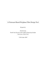
3.2. PROJECT DELIVERABLES4. Each <strong>node</strong> must provide support <strong>for</strong> high speed inter-<strong>node</strong> communications.5. Each <strong>node</strong> will run its own copy <strong>of</strong> an open-source operating system and <strong>parallel</strong>processing libraries. The <strong>node</strong>s will <strong>for</strong>m a MIMD processor.6. A minimum <strong>of</strong> two <strong>node</strong>s must be built to demonstrate <strong>the</strong> <strong>node</strong>s per<strong>for</strong>ming<strong>parallel</strong> processing functions.7. Speed comparisons <strong>of</strong> various networking topologies must be per<strong>for</strong>med <strong>for</strong>common <strong>parallel</strong> algorithms.3.2 Project DeliverablesThe fundamental goal <strong>of</strong> this project is to produce a working <strong>node</strong> <strong>for</strong> a Parallel ProcessingUnit (PPU) and to demonstrate a simple, <strong>hardware</strong> accellerated <strong>parallel</strong> algorithmrunning on <strong>the</strong> <strong>node</strong>. The <strong>node</strong>s are to be comprised <strong>of</strong> a configurable logicunit and a general purpose microprocessor with supporting <strong>hardware</strong>. Each <strong>node</strong> isrequired to run an open-source operating system and demonstrate a <strong>parallel</strong> processingexample.The system is to be configurable in s<strong>of</strong>tware and <strong>hardware</strong>. S<strong>of</strong>tware configurabilitymeans <strong>the</strong> ability to change <strong>the</strong> algorithms and s<strong>of</strong>tware running on <strong>the</strong> system.Hardware configurability is <strong>the</strong> ability <strong>of</strong> <strong>the</strong> system to change <strong>the</strong> behaviour <strong>of</strong> certainlogic components to optimise <strong>the</strong> system <strong>for</strong> specific processing needs.As secondary goals, <strong>the</strong> following deliverables should be attained: The implementation<strong>of</strong> networking protocols across <strong>the</strong> configurable communications infrastructure.The use <strong>of</strong> configurable logic <strong>for</strong> optimising various computations.As tertiary goals, dynamic re-configuration to constantly optimise <strong>the</strong> system per<strong>for</strong>manceand dynamic network configuration should be investigated.The functional <strong>hardware</strong> plat<strong>for</strong>m is <strong>the</strong> major deliverable. S<strong>of</strong>tware <strong>for</strong> <strong>the</strong> processors,configurable logic, communications interfaces, communications libraries and<strong>parallel</strong> processing libraries are also part <strong>of</strong> <strong>the</strong> deliverables.3.3 Requirements AnalysisAfter considering <strong>the</strong> requirements, it is clear that no specific <strong>hardware</strong> design constraintsare implied o<strong>the</strong>r than providing <strong>the</strong> required functionality. There<strong>for</strong>e after ananalysis <strong>of</strong> typical microprocessor systems and <strong>the</strong> requirements <strong>of</strong> a <strong>node</strong> in a <strong>parallel</strong>processor, <strong>the</strong> following more focused requirements have been developed.3.3.1 Silicon requirementsThe basic componet requirements <strong>of</strong> <strong>the</strong> <strong>reconfigurable</strong> <strong>parallel</strong> processing <strong>node</strong> areillustrated in figure 3.1.Radar Remote Sensing Group, Electrical Engineering, UCT Page: 14 <strong>of</strong> 123
CHAPTER 3. USER REQUIREMENTS AND SPECIFICATIONHigh Density RAMCPU +Bus ControllerJTAGJTAGLocal BusFPGAProcessorPrivateRAMHigh Speed RAMNetworkingMisc(Pwr,Support)CommunicationsBoot MemoryFigure 3.1: Basic Component Requirements <strong>of</strong> a Node1. Processor, a high per<strong>for</strong>mance, low power embedded processor with <strong>the</strong> capabilityto interface with a: Communications controller, FPGA and Memory Infrastructure.2. A high gate count FPGA with an interface to <strong>the</strong> processors memory bus toprovide high speed access. Advanced clock generation would be beneficial <strong>for</strong>implementing high speed designs.3. A low gate count communications FPGA with high speed interfacing technologies.The most commonly provided interfaces being Low Voltage DifferentialSignalling (LVDS) or PECL.4. E<strong>the</strong>rnet like communications infrastructure capable <strong>of</strong> at least 10Mb/s and possibly100Mb/s speeds.5. Non-volatile boot memory <strong>for</strong> standalone system operation.6. JTAG Test and Access port or similar debugging and testing interface.7. Serial communications (EIA-232) <strong>for</strong> system control and debugging.8. High speed inter-<strong>node</strong> communications infra-structure support.9. Power supplies and system control components.10. Processor/system boot-up configuration if necessary.11. Status/debugging indicators.Radar Remote Sensing Group, Electrical Engineering, UCT Page: 15 <strong>of</strong> 123
3.3. REQUIREMENTS ANALYSIS3.3.2 Mechanical requirementsBall Grid Array (BGA) and o<strong>the</strong>r high density chip packaging products are to beavoided where at all possible to reduce system cost and reduce <strong>the</strong> risk <strong>of</strong> manufactureor design error. For future designs, this limitation may be removed.The physical dimensions and interfacing connectors must comply with <strong>the</strong> requirements<strong>of</strong> <strong>the</strong> backplane or system architecure to which <strong>the</strong> <strong>node</strong>s will interface, if any.This will be specified in <strong>the</strong> specification and <strong>hardware</strong> design chapters.3.3.3 Interface requirements1. E<strong>the</strong>rnet or some o<strong>the</strong>r high speed means will provide communication and s<strong>of</strong>twaredownloading to each <strong>node</strong>.2. Serial communications must be used <strong>for</strong> debugging and console use.3. FPGA communications must use high speed (>100Mb/s) LVTTL, PECL or LVDSsignalling between <strong>node</strong>s.4. FPGAs must be memory mapped to <strong>the</strong> processor and provide an interface toprocessing and communications logic.5. Comms FPGA should have bus mastering or DMA capbitiles <strong>for</strong> fast memorytransfer operations.6. Parallel processing libraries will provide a technology independent interface <strong>for</strong>messaging between <strong>node</strong>s.7. The operating system must provide a TCP/IP link over a custom communicationschannel to allow transparent simple communications between <strong>node</strong>s.8. For <strong>the</strong> prototype <strong>hardware</strong> design developed in this <strong>the</strong>sis, an interface to astandard PC is required, possibly across <strong>the</strong> PCI bus.3.3.4 VHDL / Macro-function requirements1. Communications controller.2. Coprocessor functions.Including an FFT or DCT processor3. System bus interface controller.4. Advanced clock generation and deskewing.5. RAM buffers <strong>for</strong> communications and processing.Radar Remote Sensing Group, Electrical Engineering, UCT Page: 16 <strong>of</strong> 123
CHAPTER 3. USER REQUIREMENTS AND SPECIFICATIONNodeNodeWorldE<strong>the</strong>rnet BusE<strong>the</strong>rnetDebuggerRS-232ParallelProcessing NodePCIControllerPCI DevicesLVDS ChannelDiskCLK IN OUTLVDS ChannelNext NodeFigure 3.2: Node interface requirements6. FPGA configuration support7. System boot and configuration3.3.5 S<strong>of</strong>tware requirements1. Operating system (Linux or eCos) ported to a <strong>node</strong>.2. E<strong>the</strong>rnet or equivalent networking: Programming, control, messaging.3. FPGA run-time reconfiguration if FPGA supports it.4. Interfacing with FPGA processor and communications.5. Parallel processing libraries ported to OS/communications network.6. Test suites.3.4 System Specifications3.4.1 Processing Algorithms1. FFT or DCT algorithm demonstration.2. Parallel execution <strong>of</strong> algorithms.Radar Remote Sensing Group, Electrical Engineering, UCT Page: 17 <strong>of</strong> 123
3.5. TEST SPECIFICATIONS3.4.2 Communications1. GDB / Custom debugging interface via RS-232 channels.2. TCP/IP Stack over E<strong>the</strong>rnet or equivalent.3. TCP/IP Stack on Custom Network Mesh.4. Configurable inter-<strong>node</strong> topography.3.5 Test SpecificationsThe system will initially be tested with a single <strong>node</strong> in order to develop <strong>the</strong> VHDLfirmware and port and test <strong>the</strong> operating system to <strong>the</strong> plat<strong>for</strong>m. Acceptance test proceduretests will be developed to verify <strong>the</strong> functioning <strong>of</strong> <strong>the</strong> <strong>hardware</strong> and firmwaredesigns. Testing will be per<strong>for</strong>med using <strong>the</strong> serial port and with test s<strong>of</strong>tware in <strong>the</strong>FPGA. If a direct interface to a PC system is implemented, this interface can be usedto test system components without <strong>the</strong> functioning <strong>of</strong> <strong>the</strong> processor.Later testing will be done at a higher level over a communications link and willprovide access to features such as a remote shell if <strong>the</strong> Linux operating system is usedand configuration such as programming <strong>the</strong> flash and setting up <strong>the</strong> s<strong>of</strong>tware on <strong>the</strong><strong>node</strong>.Final testing will test processing algorithms running on <strong>the</strong> processor and FPGA,verfiy <strong>the</strong> correct operation <strong>of</strong> those algorithms and finally demonstrate a <strong>parallel</strong> processingexample.Radar Remote Sensing Group, Electrical Engineering, UCT Page: 18 <strong>of</strong> 123
Chapter 4Concept StudyThe idea <strong>of</strong> a <strong>hardware</strong> and s<strong>of</strong>tware <strong>reconfigurable</strong> <strong>parallel</strong> processor is not a novelidea, however not many such systems have been developed. In most cases, <strong>the</strong> projectshave been ei<strong>the</strong>r commercial or research using proprietary technology. This makesopen research in this area more difficult due to <strong>the</strong> lack <strong>of</strong> in<strong>for</strong>mation provided and<strong>the</strong> lack <strong>of</strong> physical <strong>hardware</strong>.A <strong>hardware</strong> configurable processor with <strong>the</strong> use <strong>of</strong> open-source technology hopesto fur<strong>the</strong>r <strong>the</strong> use <strong>of</strong> open-source s<strong>of</strong>tware <strong>for</strong> <strong>parallel</strong> computing and to develop anenvironment <strong>for</strong> fur<strong>the</strong>r <strong>development</strong> and research. This chapter describes <strong>the</strong> conceptstudy undertaken at <strong>the</strong> beginning <strong>of</strong> <strong>the</strong> project in order to determine <strong>the</strong> viability andfur<strong>the</strong>r develop <strong>the</strong> requirements and specification <strong>of</strong> <strong>the</strong> system.Firstly, <strong>the</strong> requirements <strong>of</strong> <strong>the</strong> <strong>parallel</strong> <strong>node</strong> in general are discussed, this is followedby more detailed looks at <strong>the</strong> processor and <strong>reconfigurable</strong> logic. A high levelsystem design is specified followed by discussion <strong>of</strong> <strong>the</strong> various choices <strong>for</strong> inter-<strong>node</strong>communications. Finally <strong>the</strong> s<strong>of</strong>tware requirements <strong>for</strong> <strong>the</strong> system are expanded upon.The results <strong>of</strong> this study were that <strong>the</strong> project goals <strong>of</strong> developing a <strong>node</strong> <strong>for</strong> configurable<strong>parallel</strong> processing were determined to be within reach using currently availabletechnologies.4.1 Parallel <strong>node</strong> requirementsEssentially, each <strong>node</strong> needs to be capable <strong>of</strong> running as a stand-alone entity withoutsupport from o<strong>the</strong>r <strong>node</strong>s. This means that and as such, it will require some <strong>of</strong> <strong>the</strong>basic elements needed <strong>for</strong> a microprocessor system:1. Processor: This can be ei<strong>the</strong>r a stand-alone, System On Chip (SOC) or ASICimplemented processing device. This will provide <strong>the</strong> general processing andcontrol requirements <strong>of</strong> <strong>the</strong> system.2. Memory: Memory <strong>for</strong> system and application s<strong>of</strong>tware as well as data storage isessential <strong>for</strong> <strong>the</strong> operation <strong>of</strong> a microprocessor. Types <strong>of</strong> memory that should be19
4.2. PROCESSOR REQUIREMENTSconsidered.(a) FLASH, a medium density non-volatile memory primarily <strong>for</strong> program anddata storage.(b) SRAM, a high speed memory low density memory <strong>for</strong> low latency andhigh bandwidth data storage.(c) DRAM/SDRAM, a high density memory type with reasonably high speed<strong>for</strong> program execution and high volume data storage.3. Communications. In order <strong>for</strong> a <strong>node</strong> to communicate with o<strong>the</strong>r <strong>node</strong>s, various<strong>for</strong>ms <strong>of</strong> communication may be required.(a) E<strong>the</strong>rnet networking is a well defined industry standard communicationsbus, with average bandwidth capabilities.(b) Backplane communications provide very high speed connections but canonly support a limited number <strong>of</strong> <strong>node</strong>s.(c) Custom communications can be provided though link layer chip-sets orimplemented using configurable logic devices. They have <strong>the</strong> potential <strong>for</strong>producing very high speed point-to-point or bus type connections.(d) Standard Serial. These low data rate communications may be used <strong>for</strong>control and system configuration as well to aid in debugging.4. Power supplies <strong>for</strong> <strong>the</strong> various system components and microprocessor supervisory,control and configuration devices.5. Hardware interface devices and physical connectors.To support <strong>the</strong> need <strong>for</strong> <strong>reconfigurable</strong> processing, a configurable logic device wi<strong>the</strong>nough resources to support <strong>the</strong> algorithms required will be needed.4.2 Processor requirementsThe scope <strong>of</strong> this project is to develop a basic <strong>node</strong> <strong>for</strong> <strong>parallel</strong> processing and <strong>the</strong> focusis more on <strong>the</strong> design than absolute processing speed. Where possible, devices such asBall Grid Array (BGA) will not be used because <strong>of</strong> <strong>the</strong> added design and manufactureproblems.Radar Remote Sensing Group, Electrical Engineering, UCT Page: 20 <strong>of</strong> 123
CHAPTER 4. CONCEPT STUDY4.2.1 System RequirementsThe major requirement <strong>of</strong> a processor <strong>for</strong> <strong>the</strong> <strong>parallel</strong> processor is CPU processingper<strong>for</strong>mance. The major processing tasks <strong>of</strong> <strong>the</strong> CPU will be communications andinteger/floating point ma<strong>the</strong>matics. DSP instructions may be used <strong>for</strong> particular processingalgorithms but <strong>the</strong>se will usually need to be routines written in <strong>the</strong> processorsassembly language and very carefully optimised. The Multiply And aCcumulate(MAC) features <strong>of</strong> some processors can also greatly speed up certain algorithms.The processor (with companion memory controller if necessary) must be able tointerface to SDRAM, SRAM, FLASH and <strong>the</strong> FPGA preferably with a glue-less interface.This will mean that <strong>the</strong> <strong>hardware</strong> design will be greatly simplified and <strong>the</strong> riskinvolved with interfacing to complicated devices such as SDRAM will be reduced.The ability to per<strong>for</strong>m Direct Memory Access (DMA) transfers on <strong>the</strong> bus will allow<strong>the</strong> FPGA and processor to used a shared memory arrangement which will reduce <strong>the</strong>overhead <strong>of</strong> copying data through <strong>the</strong> CPU.4.2.2 Processor SelectionThe MIPS range <strong>of</strong> processors (see [2] <strong>for</strong> MIPS in<strong>for</strong>mation) generally come in smalleasy to use packages and have very high per<strong>for</strong>mance. The MIPS instruction setsare supported by Linux, eCos and <strong>the</strong> various ’BSD open-source operating systemsand most importantly <strong>the</strong> GNU C Compilers (GCC). A port <strong>of</strong> an operating systemto <strong>the</strong> project <strong>hardware</strong> will be greatly accelerated by using existing ports to <strong>the</strong> sameprocessor architecture. In general, most mid-range MIPS processors come in a low pincount package configurations and have an interface to a support chip (companion) <strong>for</strong>memory bus and peripheral bus access.The IDT 79RC64574 [3] processor is a 64bit MIPS processor capable <strong>of</strong> runningup to 333MHz with a maximum per<strong>for</strong>mance <strong>of</strong> 444 Drystone MIPS (Millions <strong>of</strong> InstructionsPer Second) in a 128pin PQFP package. This processor features a doubleprecision floating point unit running up to 666 MFLOPS (Millions <strong>of</strong> Floating PointOperations Per Second). It also includes DSP extensions <strong>for</strong> up to 125 million multiplyand accumulates (MACs) per second, a full featured virtual memory manager and 32kbdata and 32kb instruction caches. The ’574 has a 32bit wide external data/address bus(SysAD bus) and <strong>the</strong> ’575 is 64bits wide. O<strong>the</strong>r variations <strong>of</strong> <strong>the</strong> 64bit MIPS processorsare available from IDT, NEC and Toshiba all supporting <strong>the</strong> same instruction setsand similar bus interfaces. The GNU C compiler supports <strong>the</strong> full range <strong>of</strong> standardMIPS processor instruction sets. The internal architecture <strong>of</strong> all MIPS processors arevery similar internally and are backwards compatible which makes migrating to newerdevices very easy.The embedded powerPC chips from IBM and Motorola run up to 550MHz andsupport a host <strong>of</strong> on chip peripherals. These devices typically come in <strong>the</strong> 300 to600 pin BGA package types and are very complicated to design with. These devicesare typically aimed at communication processors and support a host <strong>of</strong> interfaces andRadar Remote Sensing Group, Electrical Engineering, UCT Page: 21 <strong>of</strong> 123
4.3. RECONFIGURABLE LOGIC REQUIREMENTSfeatures. Most <strong>of</strong> <strong>the</strong> features provided are not needed <strong>for</strong> a <strong>parallel</strong> processing <strong>node</strong>.The powerPC range <strong>of</strong> devices are supported by <strong>the</strong> GCC compilers and most opensourceoperating systems.The Hitachi Super-H processor range SH-4 runs up to 200MHz delivering 360Drystone 1.1 MIPS. It comes in a 208 pin QFP or 256Pin BGA. The SH-4 has addedinstructions <strong>for</strong> vector manipulation mainly aimed at graphics processing which couldbe used <strong>for</strong> accelerating certain algorithms. There is not a wide range <strong>of</strong> <strong>the</strong>se devicesavailable and backward compatibility and future support <strong>for</strong> <strong>the</strong>se processors isquestionable.Intel’s Strongarm processors run up to 235 Drystone MIPS at 206 MHz and comein a MicroBGA package. The are supported by <strong>the</strong> GCC compilers and are based on amodified ARM core. The number <strong>of</strong> devices available is limited and future continuation<strong>of</strong> this range <strong>of</strong> processors is questionable.Overall, <strong>the</strong> MIPS processors have <strong>the</strong> greatest per<strong>for</strong>mance to complexity ratio<strong>of</strong> all <strong>the</strong> processors evaluated. The are available in easy to use packages and <strong>the</strong>reare many pin compatible chips available from multiple manufacturers. The processorsare designed to be dedicated processing units and added peripherals and interfaces areavailable on a range <strong>of</strong> MIPS companion chips. Linux, eCos and BSD’s support <strong>the</strong>MIPS processor range which will greatly aid in <strong>the</strong> porting <strong>of</strong> <strong>the</strong> chosen operatingsystem.4.3 Reconfigurable logic requirementsFor an FPGA to be used as a viable device <strong>for</strong> implementing arbitrary coprocessorfunctions, <strong>the</strong> device should have <strong>the</strong> resources to support any syn<strong>the</strong>sisable design upto to some limit. In certain cases, a <strong>parallel</strong> implementation <strong>of</strong> <strong>the</strong> algorithm itself ona device can be created if <strong>the</strong> resources are available. This can allow each <strong>node</strong> in <strong>the</strong><strong>parallel</strong> system operate as internally <strong>parallel</strong> in addition to <strong>the</strong> <strong>parallel</strong>ism <strong>of</strong> <strong>the</strong> system.There is also <strong>the</strong> need to possibly implement a reduced CPU core on <strong>the</strong> FPGAdevice. This could allow more complicated processing functions to be implementedon <strong>the</strong> FPGA and reduce <strong>the</strong> amount control required from <strong>the</strong> microprocessor. Theimplemented CPU could be used to feed data into coprocessor units and write resultsback into a shared memory as an example. This CPU could also be used to per<strong>for</strong>mcommunications functions and provide intelligent switching <strong>of</strong> <strong>the</strong> inter-<strong>node</strong> communicationlinks.A device in <strong>the</strong> order <strong>of</strong> a 1 million gate FPGA will provide <strong>the</strong> flexibility to implementa very wide range <strong>of</strong> functions and provide <strong>the</strong> resources to implement multiplecopies <strong>of</strong> simpler functions to create a super-scalar system. However <strong>the</strong>se devices arevery expensive and a lower gate count device should probably be used <strong>for</strong> <strong>the</strong> prototypeimplementation.To experiment with high speed interconnects, <strong>the</strong> FPGA used must support highspeed I/O such as LVDS (Low Voltage Differential Signalling) serial channels whichRadar Remote Sensing Group, Electrical Engineering, UCT Page: 22 <strong>of</strong> 123
CHAPTER 4. CONCEPT STUDYcan run up to 840Mb/s in some FPGAs. The FPGA-CPU interface must be capable <strong>of</strong>handling <strong>the</strong> full burst rate <strong>of</strong> <strong>the</strong> bus. This should allow maximum data throughputacross this interface.The Xilinx Virtex-E FPGAs [4] support multiple (limited by device pin count)622Mb/s LVDS channels running <strong>of</strong>f a single clock channel. They do not provideany <strong>hardware</strong> serialiser/deserialiser (SERDES) circuitry however <strong>the</strong> application notesprovide reference designs to implement <strong>the</strong>se in low-level components. All <strong>the</strong> XilinxVirtex-E devices provide LVDS support.The Altera APEX20KE/C devices support up to 16 622Mb/s channels on predefinedpins. Only devices in <strong>the</strong> KE and KC range with greater than 400,000 gatessupport LVDS. These devices do however provide <strong>hardware</strong> SERDES units howeverlack flexibility in <strong>the</strong>ir use.4.4 High level system designThe structure <strong>of</strong> each <strong>node</strong> in <strong>the</strong> <strong>parallel</strong> processor will be identical from a <strong>hardware</strong>perspective. At some stage, certain <strong>node</strong>s in <strong>the</strong> system may be required to per<strong>for</strong>mdifferent tasks. There<strong>for</strong>e, <strong>the</strong> design <strong>of</strong> a <strong>node</strong> must make provision <strong>for</strong> general purposecomputing functions in addition to <strong>the</strong> <strong>hardware</strong> <strong>reconfigurable</strong> processing units.Each <strong>node</strong> will contain a MIPS based processor preferably an IDT or NEC MIPSR4000 or R5000 64bit device. These devices can double <strong>the</strong> integer per<strong>for</strong>mance <strong>of</strong>32bit processors when used correctly under certain conditions. The IDT processorsalso provide a high speed floating point unit that operates in <strong>parallel</strong> with <strong>the</strong> integerunit and employs dual issue support to create a scalar piplined architecture. This meansthat <strong>the</strong> processor can execute a single integer and floating point instruction simultainiously.These devices also provide multiply and accumulate and o<strong>the</strong>r DSP extensionswhich can be utilised. These processors also all have advanced memory managementwhich support advanced operating systems like Linux and BSD. This can be usedto create a totally <strong>hardware</strong> independant environment <strong>for</strong> applications to execute inwhich means that <strong>the</strong>y can be very easily ported to o<strong>the</strong>r <strong>hardware</strong> plat<strong>for</strong>ms. Movingbetween MIPS plat<strong>for</strong>ms will in most cases not even require a recompile.The IDT MIPS processor requires an interface chip to provide memory interfacesand peripheral bus support <strong>for</strong> <strong>the</strong> system. The interface chip per<strong>for</strong>ms <strong>the</strong> interfacingand controlling <strong>of</strong> <strong>the</strong> various memory components without processor intervention.The interface chip will connect to at least 16MB <strong>of</strong> SDRAM memory possiblysupporting DIMM <strong>for</strong>mat modules or on board devices. There will also be a 16Mbit<strong>of</strong> Boot FLASH memory <strong>for</strong> boot loader and operating system storage.A Xilinx FPGA will be connected with an SRAM or similar interface (configurable)to <strong>the</strong> memory bus. The Xilinx FPGA’s provide a greater flexability <strong>for</strong> designand support LVDS channels in all <strong>the</strong> Virtex-E devices.The FPGA will have a high speed SRAM device directly connected to it <strong>for</strong> privatehigh speed data storage. This removes <strong>the</strong> problem <strong>of</strong> having <strong>the</strong> FPGA compete <strong>for</strong>Radar Remote Sensing Group, Electrical Engineering, UCT Page: 23 <strong>of</strong> 123
4.5. COMMUNICATION INFRASTRUCTURE CHOICES<strong>the</strong> usage <strong>of</strong> <strong>the</strong> processor local bus.The FPGA will provide at least four LVDS channels <strong>for</strong> point-to-point inter-<strong>node</strong>high speed serial commmunication.The low speed memory devices (FLASH) may need to be located on a peripheralbus to reduce <strong>the</strong> loading <strong>of</strong> <strong>the</strong> local bus.The prototype <strong>hardware</strong> plat<strong>for</strong>m will interface to a standard PC system via <strong>the</strong>PCI bus. This will allow <strong>the</strong> devices in <strong>the</strong> system to be accessed transparently from<strong>the</strong> host PC which will greatly aid in <strong>development</strong>, debugging and also provide communicationscapabilities. Devices on <strong>the</strong> PCI bus may be accessed by a <strong>node</strong> in <strong>the</strong>system if it provides bus master support. This <strong>for</strong> example will allow <strong>node</strong>s to accessstandard PCI e<strong>the</strong>rnet controllers. At a later stage, <strong>the</strong> <strong>node</strong>s could be connected to apassive PCI backplane <strong>for</strong> standalone operation. Because <strong>the</strong> <strong>node</strong>s will interface to aPC system, <strong>the</strong>y must con<strong>for</strong>m to <strong>the</strong> specifications <strong>of</strong> <strong>the</strong> PCI bus.4.5 Communication infrastructure choicesThe various <strong>parallel</strong> processor systems examined during <strong>the</strong> pre-study use a variety<strong>of</strong> different networking topologies. Some were limited to <strong>the</strong> system <strong>hardware</strong> capabilitieswhile o<strong>the</strong>rs implemented complex communications processors. By using aconfigurable logic device, we have <strong>the</strong> freedom to implement a wide variety <strong>of</strong> communicationsstructures if <strong>the</strong> basic physical interconnects are well planned.The various options <strong>for</strong> a network topology are as follows:1. A serial chain or loop <strong>of</strong> <strong>node</strong>s. In this system, each <strong>node</strong> will contain twolinks to two opposite neighbours. This system has <strong>the</strong> advantage that switchingand communications s<strong>of</strong>tware can be implemented in a very simple manner.A message to any <strong>node</strong> can be broadcast in both directions (or one directionin a loop) and be passed from <strong>node</strong> to <strong>node</strong> until <strong>the</strong> addressed <strong>node</strong> receives<strong>the</strong> message. There is however a very low level <strong>of</strong> connectivity and <strong>the</strong> totalcommunications bandwidth is limited to <strong>the</strong> bandwidth <strong>of</strong> one link.2. A square matrix <strong>of</strong> <strong>node</strong>s. This is a common structure and is most notably usedby <strong>the</strong> Intel Paragon supercomputers. Each <strong>node</strong> has a link to its neighbour onfour sides. Messages are routed though <strong>node</strong>s using routing algorithms. Thetotal bandwidth <strong>of</strong> <strong>the</strong> network is much lager than <strong>the</strong> chain topology as <strong>the</strong>reare multiple paths between any two <strong>node</strong>s and a message only uses one path,leaving <strong>the</strong> o<strong>the</strong>r paths free <strong>for</strong> o<strong>the</strong>r <strong>node</strong>s.3. Cubic and hyper-cube structures are also possible, however <strong>the</strong> <strong>hardware</strong> ands<strong>of</strong>tware becomes increasingly more complicated.4. A Tree structure. These types <strong>of</strong> networks are useful when implementing analgorithm where jobs are dispatched from a central <strong>node</strong> and all results are returnedback to that <strong>node</strong>. No inter-<strong>node</strong> communications o<strong>the</strong>r than with <strong>the</strong>Radar Remote Sensing Group, Electrical Engineering, UCT Page: 24 <strong>of</strong> 123
CHAPTER 4. CONCEPT STUDYmaster <strong>node</strong> is per<strong>for</strong>med. In this situation, <strong>the</strong> number <strong>of</strong> paths from <strong>the</strong> master<strong>node</strong> to <strong>the</strong> fur<strong>the</strong>rest <strong>node</strong> is minimised <strong>for</strong> a <strong>node</strong> with a fixed number <strong>of</strong>interconnects.5. A star network. These networks are normally made <strong>of</strong> non-symmetric <strong>node</strong>swith a central communications <strong>node</strong> having much greater IO capabilities to <strong>the</strong>rest <strong>of</strong> <strong>the</strong> <strong>node</strong>s. The aim <strong>of</strong> this project however is to develop a low cost system<strong>of</strong> generic <strong>node</strong>s.6. A Bus network. Each <strong>node</strong> will have support <strong>for</strong> E<strong>the</strong>rnet networking whichis a bus structure. Thus a bus structure need not be considered <strong>for</strong> <strong>the</strong> customtopology. The E<strong>the</strong>rnet bus may be switched to make <strong>the</strong> system act as if it wasfully connected.Based on <strong>the</strong>se various structures, a square matrix <strong>of</strong> <strong>node</strong>s configuration is simpleto implement and allows <strong>for</strong> configurable topologies. This will give each <strong>node</strong> fourbidirectional configurable ports <strong>for</strong> interfacing to o<strong>the</strong>r <strong>node</strong>s. Each port may consist<strong>of</strong> one or more pairs <strong>of</strong> LVDS channel depending on <strong>the</strong> FPGA resources.The configurability <strong>of</strong> <strong>the</strong> FPGAs will also allow <strong>for</strong> <strong>the</strong> <strong>node</strong>s to be reconfigured ina ring or torus by linking <strong>the</strong> outer <strong>node</strong>s <strong>of</strong> opposite sides <strong>of</strong> <strong>the</strong> matrix. The networkcan also be reconfigured in to a tree structure by changing <strong>the</strong> routing with each <strong>node</strong>supporting up to three children.This structure can also be used to investigate using <strong>the</strong> FPGAs to switch trafficthrough one port and out ano<strong>the</strong>r to provide transparent access between <strong>node</strong>s andreduce message handling by each <strong>node</strong> between <strong>the</strong> two communicating <strong>node</strong>s. Thisproject however will focus on <strong>the</strong> <strong>hardware</strong> design and basic system functionality and<strong>the</strong>se options will be left <strong>for</strong> future work.4.6 S<strong>of</strong>tware requirementsThe primary requirement <strong>for</strong> <strong>the</strong> system is to port an operating system to <strong>the</strong> <strong>hardware</strong>plat<strong>for</strong>m and to demonstrate <strong>the</strong> processing capbilities <strong>of</strong> a single <strong>node</strong>. Fur<strong>the</strong>r workmust demonstrate <strong>the</strong> ability <strong>for</strong> inter-<strong>node</strong> communications and demonstrate a simpleexample.All <strong>the</strong> s<strong>of</strong>tware required <strong>for</strong> this project is required to be built on open-sourceprojects and tools. The <strong>development</strong> tools and operating systems selected will be opensourceand most <strong>of</strong> <strong>the</strong> standard <strong>parallel</strong> computing libraries especially MPI and PVMalready open-source projects.The operating systems available <strong>for</strong> running on <strong>the</strong> MIPS plat<strong>for</strong>m are: Linux,eCos, NetBSD, L4, QNXNetBSD [5] runs on a host <strong>of</strong> MIPS based machines and on <strong>the</strong> NEC and Toshibabased MIPS palm-top devices as well as some Silicon Graphics machines. The NetBSDkernel provides support <strong>for</strong> a host <strong>of</strong> plat<strong>for</strong>m independent architectures including PCI,Radar Remote Sensing Group, Electrical Engineering, UCT Page: 25 <strong>of</strong> 123
4.6. SOFTWARE REQUIREMENTSISA, E<strong>the</strong>rnet, USB and o<strong>the</strong>r commercial busses. The strong point <strong>of</strong> NetBSD is thatit has been designed specifically portability and runs on multiple architectures. It canalso run Linux applications with <strong>the</strong> aid <strong>of</strong> a compatibility mode or layer. The GNUtools are <strong>the</strong> primary <strong>development</strong> base used <strong>for</strong> <strong>the</strong> NetBSD.Linux [6] has been ported to <strong>the</strong> MIPS processors in at least two <strong>for</strong>ms, <strong>the</strong> standardkernel and real-time Linux. The Standard GNU tools are used to develop code <strong>for</strong> <strong>the</strong>Linux MIPS plat<strong>for</strong>m. Linux supports many <strong>of</strong> <strong>the</strong> R4000 and R5000 based MIPSchips except those with an on-chip L2 cache controller. The IDT MIPS processors donot have this feature and thus should pose little problems.eCos [7] supports <strong>the</strong> NEC Vr4300 64bit MIPS processors. eCos however is ahard-realtime system and thus does not use memory management and is staticly compiled.This make changing applications or running multiple aplications simultainiouslymuch more difficult.The L4 microkernel is a real-time kernel and runs on <strong>the</strong> R4000 MIPS CPUs but alarge percentage <strong>of</strong> it is hard coded assembler which may prove difficult to port. (see[8]) User mode Linux can run under <strong>the</strong> L4 kernel, however <strong>for</strong> this project, a real-timesystem is not neeed and may prove unnecessary.QNX is a non-opensource, free to use operating system that support <strong>the</strong> IDT MIPSprocessors. It <strong>the</strong>re<strong>for</strong>e is not fitting <strong>of</strong> this project.In general, NetBSD, eCos and Linux all use <strong>the</strong> GNU compiler tools which providesgeneric support <strong>for</strong> <strong>the</strong> various MIPS versions. This means that <strong>the</strong> main portingrequirements <strong>for</strong> <strong>the</strong>se operating system will be <strong>the</strong> provision <strong>of</strong> devices specificdrivers and bootup initialisation code.Radar Remote Sensing Group, Electrical Engineering, UCT Page: 26 <strong>of</strong> 123
Chapter 5Hardware Design and ImplementationAfter <strong>the</strong> requirements analysis and specification was per<strong>for</strong>med, <strong>the</strong> <strong>hardware</strong> designwas developed. This chapter describes <strong>the</strong> <strong>hardware</strong> design process and <strong>the</strong> implementation<strong>of</strong> that design. The design process is presented starting from <strong>the</strong> high leveldesign showing major functional units and <strong>the</strong>ir methods <strong>of</strong> interaction. Increasinglymore detailed design descriptions <strong>of</strong> each functional unit and sub-parts <strong>the</strong>re<strong>of</strong> areprovided. The entire design would be too large to cover in a single low-level description.Various difficulties and complicated design choices are explained in fur<strong>the</strong>r detailwhere applicable.The design <strong>of</strong> <strong>the</strong> system and each sub-section was specified to con<strong>for</strong>m to <strong>the</strong>requirements and specifications laid out in Chapter 3. The design choices made areindicated with motivations <strong>for</strong> <strong>the</strong> various choices given. Implementation details areprovided <strong>for</strong> each module to give an understanding <strong>of</strong> <strong>the</strong> low-level functioning <strong>of</strong> <strong>the</strong>components in <strong>the</strong> system.5.1 Processing Node ComponentsAfter <strong>the</strong> review stage, specific processor, companion devices, memory and FPGAdevices were chosen <strong>for</strong> <strong>the</strong> design. The major components needed chosen and sourcedearly in <strong>the</strong> project be<strong>for</strong>e <strong>the</strong> design had been finalised because <strong>of</strong> long lead times.The processor chosen <strong>for</strong> <strong>the</strong> project was <strong>the</strong> IDT 79RC64754 64-bit MIPS RISCmicroprocessor [3]. This part was chosen <strong>for</strong> a number <strong>of</strong> reasons. It has 32-bit wideexternal data bus would make <strong>hardware</strong> design much easier and cheaper and reduce <strong>the</strong>risk involved in designing with a 64-bit bus. The device provides a double precisionfloating point unit which operates in <strong>parallel</strong> with <strong>the</strong> integer unit through a dual-issuearchitecture. Finally, <strong>the</strong> device is packaged in an easy to use 128 pin package.The MIPS companion device selected <strong>for</strong> <strong>the</strong> project is <strong>the</strong> Galileo GT64115 [9].This was selected primarily because it interfaces <strong>the</strong> same 32-bit SysAD bus as <strong>the</strong>IDT processor. It also has an integrated PCI bus master interface which would makeinterfacing <strong>the</strong> PCI bus simple. An on chip SDRAM and memory controller allows27
5.2. DESIGN CHOICES<strong>for</strong> a ’glueless’ interface to SDRAM. To access SRAM and FLASH devices however,a bridge or bus decoder circuitry is required. Examples are given <strong>for</strong> designing suchinterfaces in <strong>the</strong> datasheets.The FPGA chosen is <strong>the</strong> Xilinx XCV200E, 200,000 gate device in a 240 pin package.This device provides up to 64 LVDS pairs, 114k bits <strong>of</strong> block RAM and 20I/O standards. The major factor influencing this choice was cost. Higher gate countFPGA’s are available <strong>for</strong> later use but at a much higher cost.O<strong>the</strong>r core components required are SDRAM <strong>for</strong> main processor memory, FLASHmemory <strong>for</strong> program storage, SRAM buffers and supervisory devices. Also essentialare power supplies <strong>for</strong> <strong>the</strong> various components.5.2 Design ChoicesThis section describes three possible system implementation architectures and lists <strong>the</strong>pros and cons associated with each. The final implementation details differ from <strong>the</strong>sedesigns which are from early in <strong>the</strong> design phase. They do however give an indication<strong>of</strong> <strong>the</strong> basic system architectures.5.2.1 Choice ASee figure 5.1.The FPGA is acts <strong>the</strong> bridge between <strong>the</strong> local bus and <strong>the</strong> peripheral bus.Advantages£High speed operation with minimal loading on memory/data bus.Direct 32-bit interface to FPGA maximises data transfer rates and allows DMA£access.FPGA can per<strong>for</strong>m DMA transfers direct to SDRAM / PCI bus. This reduces£CPU usage <strong>for</strong> data transfer and doubles memory bandwidth.FPGA and CPU ROM allows stand-alone system operation (Without host system£intervention).£SRAM cache memory <strong>for</strong> high speed FPGA reconfiguration.£Partial reconfiguration possible via direct PCI I/O operations.£Single CPLD <strong>for</strong> system configuration and FPGA configuration management.£Simpler routing <strong>of</strong> PCB.Radar Remote Sensing Group, Electrical Engineering, UCT Page: 28 <strong>of</strong> 123
ReadyA/DVCC OKCASHandShakeALECHAPTER 5. HARDWARE DESIGN AND IMPLEMENTATIONJTAGHeaderResetEEPROMDataCLK2.5VNMI(Possibly 5V)Clock
5.2. DESIGN CHOICESDisadvantagesFPGA requires a simple default configuration to allow access to CPLD and£SRAM <strong>for</strong> reconfiguration from <strong>the</strong> CPU and PCI bus.Cannot per<strong>for</strong>m direct I/O full configuration <strong>of</strong> FPGA, must be cached in SRAM£first.£FPGA configuration errors will prevent system operation.£Peripheral bus operation dependent on FPGA operation.5.2.2 Choice BSee figure 5.2.The FPGA resides on <strong>the</strong> local bus along with a separate CPLD to act as a bridgeto <strong>the</strong> peripheral bus.Advantages£High speed operation with greater loading on memory/data bus.Direct 32-bit interface to FPGA maximises data transfer rates and allows DMA£access.FPGA can per<strong>for</strong>m DMA transfers direct to SDRAM / PCI bus. This reduces£CPU usage <strong>for</strong> data transfer and doubles memory bandwidth.FPGA and CPU ROM allows stand-alone system operation (Without host system£intervention).£SRAM cache memory <strong>for</strong> high speed FPGA reconfiguration.£Full/partial reconfiguration possible via direct/cached PCI I/O operations.Hardwired peripheral bus though CPLD device not dependent on FPGA operation.£Disadvantages£Greater loading on high speed memory bus.£Two CPLDs may be necessary.£More complex PCB routing.Radar Remote Sensing Group, Electrical Engineering, UCT Page: 30 <strong>of</strong> 123
PCI InterfaceControlSysADCSysCmdVCC OKA/DMPPBankCHAPTER 5. HARDWARE DESIGN AND IMPLEMENTATIONPower Supply3.3V, 2.5V, 1.8VResetEEPROMDataCLKNMI(Possibly 5V)Clock
5.3. HIGH LEVEL SYSTEM DESIGN5.2.3 Choice CSee figure 5.3.The FPGA resides on <strong>the</strong> peripheral bus, with only a CPLD device and SDRAMon <strong>the</strong> local bus.Advantages£Reduced loading on memory/data bus.FPGA and CPU ROM allows stand-alone system operation (Without host system£intervention).£SRAM cache memory <strong>for</strong> high speed FPGA reconfiguration.£Full/partial reconfiguration possible via direct/cached PCI I/O operations.Hardwired peripheral bus though CPLD device not dependent on FPGA operation.££Simpler PCB routing.Disadvantages£Buffered access to FPGA reduces interface speed.£Two CPLDs may be necessary.£DMA operations may not be possible.£Full bus width probably not available to FPGA, per<strong>for</strong>mance implications.5.3 High Level System DesignThe basic architecture from design option B in <strong>the</strong> previous section was selected <strong>for</strong><strong>the</strong> design. The major design feature <strong>of</strong> this setup is that <strong>the</strong> FPGA is located on <strong>the</strong>local bus <strong>of</strong> <strong>the</strong> memory controller along with a separate ’Bus CPLD’ that will act asa bridge to <strong>the</strong> peripheral bus as well as providing <strong>the</strong> logic required to configure <strong>the</strong>FPGA.The MIPS CPU to be used requires various interfaces to be provided <strong>for</strong> operation.Most importantly, <strong>the</strong> processor bus (SysAD bus) needs [3, 15-1] to interfacewith a memory controller. The GT64115 controller provides a directly compatible interfacewhich will serve this function. The processor requires various interrupt inputswhich are provided by <strong>the</strong> various active components <strong>of</strong> <strong>the</strong> system. All possible futureinterrupt sources must be accommodated <strong>for</strong> in order to make <strong>the</strong> design moreRadar Remote Sensing Group, Electrical Engineering, UCT Page: 32 <strong>of</strong> 123
CHAPTER 5. HARDWARE DESIGN AND IMPLEMENTATIONPower Supply3.3V, 2.5V, 1.8VVCCOK ResetEEPROMCLK Data NMI(Possibly 5V)Clock= 16MB3.3V3.3V1.8VI2CXilinx FPGA XCV200EVirtex-ELVDSRTCWatchdog3.3VConfAddrData3.3V512kx16FastSRAMControlDataAdr3.3VRS2328-bitBootFlash(8MBit)8-bitUserFlash(16Mbit)8-bitFPGAConfFlash(2Mbit)8-bitFPGAConfSRAM(2Mbit)3.3V3.3V3.3V3.3VFigure 5.3: Design architecture choice CRadar Remote Sensing Group, Electrical Engineering, UCT Page: 33 <strong>of</strong> 123
5.3. HIGH LEVEL SYSTEM DESIGNgeneric. The configurable logic devices provide fur<strong>the</strong>r possibilities. The processoralso requires a configuration bit-stream which must be provided by ei<strong>the</strong>r an EEP-ROM memory or dynamically generated. This will be one <strong>of</strong> <strong>the</strong> functions providedby a ’Config CPLD’.The memory controller does not require any interfaces its self, it merely providesfunctions <strong>for</strong> <strong>the</strong> requirements <strong>of</strong> <strong>the</strong> system. The need <strong>for</strong> high speed high densitymemory is satisfied by inexpensive SDRAM and <strong>the</strong> memory controller provides aninterface <strong>for</strong> controlling this memory.The FPGA will have a direct connection to <strong>the</strong> local bus. By providing as manybus signals as possible to <strong>the</strong> FPGA device, <strong>the</strong> configurability and options available<strong>for</strong> implementation is kept high. It also introduces <strong>the</strong> possibility <strong>for</strong> <strong>the</strong> FPGA toemulate <strong>the</strong> memory controller if it has access to all <strong>the</strong> required signals. The FPGAhas <strong>the</strong> following modes <strong>of</strong> configuration: JTAG, Serial bitstream and 8-bi Parallel.JTAG programming is very simple and works reliably with a simple JTAG programmer.Support <strong>for</strong> JTAG programming will be provided <strong>for</strong> initial system testing and asa backup in <strong>the</strong> event that o<strong>the</strong>r methods do not work. Serial configuration requires aspecial protocol or serial memory device to program <strong>the</strong> FPGA. The FPGA’s <strong>parallel</strong>programming interface is <strong>the</strong> fastest method available <strong>for</strong> configuration. The interfaceis 8-bits wide and can interface a standard memory bus with some additional signals<strong>for</strong> <strong>the</strong> controller <strong>of</strong> <strong>the</strong> bus to use. The ’Bus CPLD’ will control <strong>the</strong> generation <strong>of</strong><strong>the</strong>se signals and allow <strong>for</strong> <strong>parallel</strong> programming <strong>of</strong> <strong>the</strong> FPGA via its interface connectedto <strong>the</strong> peripheral bus. FPGA devices have some internal RAM blocks whichoperate at very high speeds. For complicated processing algorithms however, morememory is required than available in <strong>the</strong> device (XCV200E has 114kbits). For thisreason, a high speed 4Mbit SRAM device will be provided with a dedicated interfaceto <strong>the</strong> FPGA.The system requires a standard serial connection <strong>for</strong> use as a system console anddebugging. Devices are available that will provide this interface which would interfaceto <strong>the</strong> peripheral bus. The logic used to implement RS-232 links <strong>for</strong> example on <strong>the</strong>o<strong>the</strong>r hand use relatively few resources in an FPGA. By using <strong>the</strong> FPGA to implement<strong>the</strong> serial link, <strong>the</strong> flexibility to change <strong>the</strong> physical and s<strong>of</strong>tware interfaces whenrequired is provided. For <strong>the</strong>se reasons, it was decided to implement <strong>the</strong> serial portfunctions in <strong>the</strong> FPGA.The processor requires non-volatile memory <strong>for</strong> program storage if a <strong>node</strong> is tooperate stand-alone. A Linux kernel and simple filesystem which is enough to get <strong>the</strong>system fully functional requires at least 1-2MB <strong>of</strong> storage. For this reason, a 16Mbit(2MB) FLASH device will be provided <strong>for</strong> processor boot-up. The FPGA logic designsmay also be required to reside in non-volatile storage. The XCV200E FPGAwhich is to be used requires 1.442Mbits (180kB) per configuration. The FPGA deviceused however is upward compatible to a 600,000 gate device which will require 4Mbits<strong>of</strong> configuration. In order to accommodate <strong>for</strong> this and to provide <strong>for</strong> <strong>the</strong> possibility <strong>of</strong>storing multiple configurations, an 8Mbit FLASH device was chosen. This will allow<strong>for</strong> up to five configurations <strong>for</strong> <strong>the</strong> XCV200E to be stored.Radar Remote Sensing Group, Electrical Engineering, UCT Page: 34 <strong>of</strong> 123
CHAPTER 5. HARDWARE DESIGN AND IMPLEMENTATIONThe number <strong>of</strong> LVDS channels provided will depend on <strong>the</strong> available pin resourcesafter <strong>the</strong> routing <strong>of</strong> o<strong>the</strong>r components to <strong>the</strong> FPGA and <strong>the</strong> number <strong>of</strong> lines availableto <strong>of</strong>f board connectors.A watchdog timer and real-time clock device are desirable <strong>for</strong> system time keepingand recovering from system errors. These devices typically interface to a microprocessorbus or provide a serial interface such as ¤¦¥¨§ . The choice <strong>of</strong> device will largelybe decided by component availability and interfacing complexity required. The lower<strong>the</strong> complexity <strong>the</strong> more favourable <strong>the</strong> device.If cost and PCB space allows, a user FLASH device may be provided <strong>for</strong> miscellaneousdata storage.Finally, <strong>the</strong> various components require power supplies that are capable <strong>of</strong> supplying<strong>the</strong> required current in addition to complying with device tolerances in terms <strong>of</strong>noise and voltage accuracy. The processor and LVDS I/O blocks <strong>of</strong> <strong>the</strong> FPGA requirea 2.5V supply, <strong>the</strong> CPLD devices, GT64115 and FPGA I/O require 3.3V and <strong>the</strong> clockoscillator requires a 5V supply. Switch mode power supplies are most likely to be useddue to <strong>the</strong> relatively high current requirements and to reduce power loss.5.4 Functional Unit DesignThis section gives a detailed description <strong>of</strong> <strong>the</strong> design process <strong>for</strong> each <strong>of</strong> <strong>the</strong> majorfunctional units in <strong>the</strong> design.5.4.1 MicroprocessorThe chosen microprocessor was <strong>the</strong> IDT 79RC64574 64-bit MIPS processor [3]. Theinternal functional structure to <strong>the</strong> device is very simple and optimised <strong>for</strong> per<strong>for</strong>mance.As can be seen in figure 5.4, <strong>the</strong> processor has multiple control and executionunits. The two execution units, <strong>the</strong> 64-bit Integer and Floating point unit operate in<strong>parallel</strong>, each with a five stage pipeline that is fed by a dual-issue instruction fetchunit. This allows both units to operate full speed simultainiously. The instruction fetchunit is coupled to <strong>the</strong> cache controller which finds cached entries and per<strong>for</strong>ms externalrequests when cache misses occur. The processor also has a system control processorwhich manages interrupts, cache and memory management functions.From <strong>the</strong> external view, <strong>the</strong> processor has clock, interrupt, configuration, JTAG andSysAD bus interfaces which are shown in figure 5.5. The processor clock is derivedfrom <strong>the</strong> system clock by multiplication in an on-chip Phase Locked Loop (PLL). ThePLL is sensitive to noise and thus requires its own isolated power supply to ensureproper operation. This was provided by filtering <strong>the</strong> PLL power supply though an LCcircuit, effectively acting as a low-pass filter. The processor has 7 external interruptinputs: Six normal inputs and one Non-Maskable Interrupt (NMI). The sources <strong>of</strong>normal interrupts are: An interrupt from <strong>the</strong> memory controller which can be laterdecoded into memory errors, DMA transfers and PCI interrupts. An interrupt from <strong>the</strong>Radar Remote Sensing Group, Electrical Engineering, UCT Page: 35 <strong>of</strong> 123
5.4. FUNCTIONAL UNIT DESIGNPLL64-bitIntegerExecutionUnitDSPAcceleratorIEEE1284Floating-PointAcceleratorDual-Issue Instruction Fetch UnitPrimary Cache ControllerRC5000CompatibleSystem ControlProcessor48-entry96-pageTLB32kB2 set-associativeInstructionCache(Locakable)32kB2 set-associativeDataCache(Locakable)Clk In32-bitRC64474 CompatibleSystem Interface(SysAD bus)Figure 5.4: RC64574 Functional Block Diagrameach <strong>of</strong> <strong>the</strong> FPGA, Bus CPLD and Config CPLD which are to be used <strong>for</strong> applicationspecific purposes. The possibility <strong>for</strong> accepting interrupts from <strong>the</strong> PCI bus directly isallowed by routing a PCI interrupt line though <strong>the</strong> Bus CPLD which has 5V tolerantinputs. The processor can only accept a maximum 3.3V input voltage.The processor configuration interface has five signals which need monitoring andcontrol. There are three reset signals which are generated from <strong>the</strong> Config CPLD andtwo signals used <strong>for</strong> processor configuration. The processor configuration interfaceuses a simple serial bit-stream. This can be generated by <strong>the</strong> Config CPLD and support<strong>for</strong> this is provided. In <strong>the</strong> event that this is not possible, provision is made <strong>for</strong> using aserial EEPROM device to configure <strong>the</strong> processor.The processor supports <strong>the</strong> JTAG test and debug port and allows boundary scanand instruction execution. The JTAG interface can prove very useful <strong>for</strong> debuggingand <strong>the</strong> processor was added to <strong>the</strong> system JTAG chain.The processors 32-bit MIPS SysAD external interface matched <strong>the</strong> interface on <strong>the</strong>Galileo memory controller. A direct connection between <strong>the</strong> two devices along with<strong>the</strong> relevant pull-up and pull-down resistors required were added as per <strong>the</strong> recommendationprovided in <strong>the</strong> device datasheets.O<strong>the</strong>r than <strong>the</strong>se features, <strong>the</strong> processor provides no o<strong>the</strong>r on chip peripheralswhich need to be interfaced.Radar Remote Sensing Group, Electrical Engineering, UCT Page: 36 <strong>of</strong> 123
CHAPTER 5. HARDWARE DESIGN AND IMPLEMENTATIONSystem ClockInt[0..5], NMIPowerFilterClock Interrupts ConfigJTAGPower 2.5V64-bit79RC64574SysAD 32-bit Interface32-bit AD CMD ControlFigure 5.5: RC64574 Interfaces5.4.2 Memory ControllerThe Galileo GT64115 MIPS companion, PCI and memory controller device was selectedto provide access to <strong>the</strong> PCI bus and memory devices. It supports three maininterfaces, a 32-bit MIPS SysAD bus, a 32-bit PCI interface (up to 66MHz) and a32-bit SDRAM and Device local bus interface. See figure 5.6. On <strong>the</strong> local bus, <strong>the</strong>memory controller supports up to four banks <strong>of</strong> SDRAM and provides five devicechip-select signals which includes a chip-select <strong>for</strong> <strong>the</strong> boot memory.Like <strong>the</strong> processor, this device uses an internal PLL device <strong>for</strong> clock generationand required a power supply filter <strong>for</strong> correct operation.The SysAD and PCI bus interfaces were connected up according to <strong>the</strong> specificationsin <strong>the</strong> datasheets. For certain signals on <strong>the</strong> PCI bus more research and exampleswere needed to clarify <strong>the</strong>ir usage such as <strong>the</strong> PCI_PRSNT1/2 signals.The local bus SDRAM interface was connected to two 16-bit SDRAM devices<strong>for</strong>ming a single 32-bit 32MB SDRAM bank. The decision was made not to use anSDRAM module due to <strong>the</strong> difficulty in obtaining parts and <strong>the</strong> possibility <strong>of</strong> overloadingand leng<strong>the</strong>ning <strong>the</strong> high speed bus. The FPGA and Bus CPLD devices a<strong>reconfigurable</strong> logic devices and as such are very flexible. Because <strong>the</strong> chip-select signalsare multiplexed on <strong>the</strong> local bus, all are available to each device. Thus, no specificchip-select signals are dedicated to ei<strong>the</strong>r device. A convention was however specified<strong>for</strong> <strong>the</strong> usage <strong>of</strong> <strong>the</strong> chip-select lines, see Table 5.1. The peripheral bus bridge is <strong>the</strong>logic implemented in <strong>the</strong> Bus CPLD to provide transparent access to device on <strong>the</strong>peripheral bus from <strong>the</strong> local bus. The local bus chip-select signal will be decoded intoaddress banks to address individual memory device.The FPGA local bus interface was provided with <strong>the</strong> full set <strong>of</strong> signals required including<strong>the</strong> memory controllers multipurpose pins which can be configured to provideRadar Remote Sensing Group, Electrical Engineering, UCT Page: 37 <strong>of</strong> 123
5.4. FUNCTIONAL UNIT DESIGNConfigSystem ClockSDRAM ControlSDRAM AddrPowerFilterClockMem ADPower 3.3VGalileoGT64115Local busMemoryInterfaceMemControlMPPPCI ADSysAD 32-bit Interface32-bitPCI
CHAPTER 5. HARDWARE DESIGN AND IMPLEMENTATIONSDRAMControllersdram Addresssdram ControlData BusSRAMControlAddressSDRAMMemoryFPGAGalileoGT641152 x FLASHBi-Dir BufferPeripheral BusBridgeLatch + DecoderMemoryControllerLocal BusFigure 5.7: Local and Peripheral Bus Configuration5.4.3 Bus CPLD and Peripheral BusThe Bus CPLD device operation has been largely discussed in previous sections. Thedevice chosen was a 144 macro cell Xilinx CPLD in a 144 pin package [10]. Thisprovided enough I/O pin resources to interface <strong>the</strong> local bus and peripheral bus alongwith providing various o<strong>the</strong>r interfaces. This device generates <strong>the</strong> address and controlsignals <strong>for</strong> <strong>the</strong> peripheral bus (master operation) and is a slave on <strong>the</strong> local bus. Thisdevice also generates <strong>the</strong> configuration signals required to program <strong>the</strong> FPGA. Thesystem JTAG interface is routed to <strong>the</strong> I/O pins <strong>of</strong> <strong>the</strong> CPLD. This allows <strong>for</strong> <strong>the</strong> JTAGchain to be accessed from <strong>the</strong> CPLD and thus from <strong>the</strong> system its self with <strong>the</strong> correctlogic design.The peripheral bus was chosen to have an 8-bit (byte) wide data bus in order toreduce PCB routing complexity. The address bus was sized to address <strong>the</strong> maximumpossible memory device on <strong>the</strong> bus. The processor boot FLASH is specified at 16Mbitbut provision was made <strong>for</strong> supporting a 32Mbit device. This meant that <strong>the</strong> addressbus needed to be 22 bits © ¥¥ "! ©# wide. . The SRAM devicechosen <strong>for</strong> general purpose storage and FPGA configuration cache was selected on <strong>the</strong>basis <strong>of</strong> availability. The device chosen was a 16-bit wide, 4Mbit device which hadalready been purchased <strong>for</strong> o<strong>the</strong>r projects. This would not however directly interfaceto <strong>the</strong> 8-bit bus. Fortunately, <strong>the</strong> device selected has two control lines <strong>for</strong> byte wideaccesses. During read and write cycles with only a single bank selected, <strong>the</strong> unselectedbank is driven to tri-state thus not affecting that side <strong>of</strong> <strong>the</strong> bus. There<strong>for</strong>e it wasdecided that both banks could be hardwired toge<strong>the</strong>r making sure that each bank wasselected individually. The Bus CPLD could <strong>the</strong>n be programmed to use <strong>the</strong> two banksas separate chip-selects, effectively accessing <strong>the</strong> upper and lower banks <strong>of</strong> <strong>the</strong> SRAMas separate devices.5.4.4 FPGAThe primary task <strong>for</strong> <strong>the</strong> FPGA in <strong>the</strong> requirements is <strong>hardware</strong> acceleration <strong>of</strong> processingalgorithms. The FPGA however also needs to provide some essential systemRadar Remote Sensing Group, Electrical Engineering, UCT Page: 39 <strong>of</strong> 123
5.4. FUNCTIONAL UNIT DESIGNsupport <strong>for</strong> <strong>the</strong> system to function. To interface to <strong>the</strong> processor, <strong>the</strong> FPGA is placedon <strong>the</strong> memory local bus to provide high speed 32-bit data access and provide <strong>the</strong>possibility <strong>for</strong> DMA transfers. The FPGA is required to implement a serial port controller(UART). This can be per<strong>for</strong>med in logic, but a RS-232 level translator device isneeded external to <strong>the</strong> FPGA to interface o<strong>the</strong>r RS-232 systems. An LT1386 EIA/TIAcompatible line driver was used. It provided <strong>the</strong> capability <strong>for</strong> two UART channelshowever only a single pair <strong>of</strong> Transmit and Receive signals were routed. The reason<strong>for</strong> this was that <strong>the</strong>re would not sufficient physical space on <strong>the</strong> board <strong>for</strong> <strong>the</strong> extrachannel. The serial port will not be used as a primary communications interface in <strong>the</strong>final system and thus only one is required.The FPGA is connected directly to a 16-bit high speed 4Mbit SRAM device whichwill provide dedicated external storage space <strong>for</strong> <strong>the</strong> processing algorithms implemented.The JTAG interface <strong>of</strong> <strong>the</strong> FPGA is connected as part <strong>of</strong> <strong>the</strong> system JTAGchain.To use <strong>the</strong> LVDS I/O capabilities <strong>of</strong> <strong>the</strong> FPGA, <strong>the</strong> I/O blocks with <strong>the</strong> LVDSchannels to be used must be powered at 2.5V. Because all <strong>the</strong> o<strong>the</strong>r interfaces <strong>of</strong> <strong>the</strong>FPGA operate at 3.3V <strong>the</strong>re was only a single I/O block available that could be used<strong>for</strong> LVDS. This I/O block provides support <strong>for</strong> eight LVDS pairs (configured four inputand four output channels) and an LVDS clock input. The LVDS clock input was notimplemented because <strong>the</strong> clock can be recovered with <strong>the</strong> aid <strong>of</strong> clock-data recoverytechniques. CAT-5 cabling is suggested <strong>for</strong> LVDS signalling and thus two RJ-45 jackswere used providing four LVDS channels over two cables. This will allow <strong>for</strong> pointto-pointcommunications between systems in a ring or square matrix configurationdepending on <strong>the</strong> cable configuration.Finally, <strong>the</strong> FPGA configuration interface was configured to allow <strong>parallel</strong> programmingon <strong>the</strong> SelectMAP interface described in <strong>the</strong> datasheets and applicationnotes.5.4.5 ClockingThe processor, memory controller and SDRAM devices all require a synchronised inphaseclock to which <strong>the</strong>y need to synchronise. The FPGA, Bus CPLD and ConfigCPLD also require clock inputs. The memory controller requires a clock greater than<strong>the</strong> frequency <strong>of</strong> <strong>the</strong> PCI clock (33MHz <strong>for</strong> PC environment) but no more than 75MHz.The processor requires a bus clock <strong>of</strong> between 33MHz and 125MHz and an internalpipeline clock greater than 100MHz. The SDRAM memory used has a maximumfrequency <strong>of</strong> 100MHz. The CPLD devices each operate up to 100MHz and <strong>the</strong> FPGAis specified at around 200-300MHz.The bus frequency was chosen to be 66MHz with <strong>the</strong> possibility <strong>of</strong> running up to75MHz. With such a high frequency bus clock and <strong>the</strong> number <strong>of</strong> devices runningfrom it, reliability problems can occur. If all <strong>the</strong> devices used <strong>the</strong> same clock, <strong>the</strong>loading on that signal would be too great and possibly cause increased jitter and signaldegradation. The o<strong>the</strong>r problem is that each device will not be guaranteed to get <strong>the</strong>Radar Remote Sensing Group, Electrical Engineering, UCT Page: 40 <strong>of</strong> 123
CHAPTER 5. HARDWARE DESIGN AND IMPLEMENTATION22RDev AClockClockDist+1nSDev BDev CDev DFigure 5.8: Clock Distribution Architectureclock in phase which will cause synchronisation problems. To solve <strong>the</strong>se problems,a clock distribution system needed to be designed with terminations to prevent reflections.A clock driver chip with ten output drivers was selected to manage <strong>the</strong> systemclock. It <strong>of</strong>fers a worst case 350ps skew between output clocks. Because each devicehas its own dedicated clock signal, <strong>the</strong> nets are single ended. [11] indicates tworecommended methods <strong>for</strong> terminating single ended clocks, source and end terminations.End terminations works well but require a resitor-capacitor network. Sourcetermination requires only a single resistor at <strong>the</strong> signal source and was chosen <strong>for</strong> itssimplicity. In addition to <strong>the</strong> low skew <strong>of</strong> <strong>the</strong> clock distribution device, <strong>the</strong> signal propagationdelays on each net need to be very close to each o<strong>the</strong>r. For this reason, <strong>the</strong> netlengths on <strong>the</strong> PCB were equalised by routing in zig-zag patterns were necessary toget <strong>the</strong> nets to within 2mm <strong>of</strong> each o<strong>the</strong>r.One particular issue that was described in an errata document from <strong>the</strong> memorycontroller was that <strong>the</strong> clock signal to <strong>the</strong> particular processor (RC64574) needed to beslightly delayed from its own clock input. The simplest method <strong>of</strong> achieving this wasto increase that clock net length to create <strong>the</strong> required signal delay <strong>of</strong> 1ns.5.4.6 Power and Peripheral DevicesThe power supplies <strong>for</strong> <strong>the</strong> system needed to be designed to be capable <strong>of</strong> handling <strong>the</strong>worst case current requirements from <strong>the</strong> various devices. These worst case calculationsare shown in table 5.2. The input voltage from <strong>the</strong> PCI is 5V and also 3.3V innewer systems. For <strong>the</strong> 3.3V and 1.8V supply, it was decided to use a buck mode (stepdown)switching regulator from <strong>the</strong> 5V supply. This was mainly in order to reduce <strong>the</strong>heat dissipation that would result from a linear regulator. For <strong>the</strong> 2.5V supply, a linearregulator was used due to concerns about noise effects on <strong>the</strong> high speed processor andLVDS channels using this supply. A heat sink was specified <strong>for</strong> use with this regulator.The switch mode supply needed special attention to be paid concerning <strong>the</strong> choice <strong>of</strong>inductors and smoothing capacitors. High ripple supply capacitors (Low ESR) andpower inductors were used with values calculated from datasheet in<strong>for</strong>mation.A real-time clock with EEPROM memory, watchdog timer and voltage monitordevice in an 8-pin SOIC package. This small device has a two ¤ ¥ § wire bus interfaceconnected to <strong>the</strong> FPGA which will implement a controller. This device satisfies <strong>the</strong>need <strong>for</strong> voltage monitor, watchdog and RTC in a single device.Radar Remote Sensing Group, Electrical Engineering, UCT Page: 41 <strong>of</strong> 123
5.5. SYSTEM CONFIGURATION OPTIONSTable 5.2: Worst case power supply calculationsDevice 5V Supply 3.3V Supply 2.5V Supply 1.8V SupplyCPU RC64574 250MHz - - 880mA -Galileo GT64115 - 250mA - -Xilinx XCV200E - 400mA 20mA 1000mASDRAM (128Mbit) - 2x140mA - -SRAM (4Mbit) - 12nS - 2x120mA - -FLASH - 90ns - 2x12mA - -Xilinx XC9572XL - 60mA - -Xilinx XC96144XL - 110mA - -Clock Distribution - 60mA - -RTC XC1227A - 2mA - -LTC1386 - 400uA - -66MHz clock 20mA - - -Total 20mA 1426mA 900mA 1000mA5.5 System Configuration OptionsOne <strong>of</strong> <strong>the</strong> aims <strong>of</strong> <strong>the</strong> <strong>hardware</strong> design was to make <strong>the</strong> system flexible and configurablein order to provide a wide range <strong>of</strong> possible configurations and reduce <strong>the</strong> risk<strong>of</strong> a design problem with an inflexible design.The configuration options provided <strong>for</strong> <strong>the</strong> Galileo memory controller are shownin Table 5.3. The interrupt and miscellaneous configuration is shown in Table 5.4.5.6 Printed Circuit Board DesignThe printed circuit board design had <strong>the</strong> constraint that <strong>the</strong> <strong>hardware</strong> needs be compatiblewith PCI in terms <strong>of</strong> physical size and layout. The board was specified to bea six layer design in order to keep manufacture prices lower although <strong>for</strong> <strong>the</strong> prototype,additional layers could be accepted if necessary. Components were restrictedto single side with only very low pr<strong>of</strong>ile passive components allowed on <strong>the</strong> back <strong>of</strong><strong>the</strong> board as per <strong>the</strong> PCI clearance constraints. Where at all possible, surface mountcomponents were used. The design was specified to keep EMC consideration in mindas <strong>the</strong> <strong>hardware</strong> was required to interface a PC system which typically produces a lot<strong>of</strong> interference and may be susceptable as well. (See [12] <strong>for</strong> EMC design)The most important aspects <strong>of</strong> <strong>the</strong> PCB design were <strong>the</strong> bus and high speed tracklayout and <strong>the</strong> component placement to optimise this. The local bus is a 32-bit widebus with additional control signals running at 66MHz to 75MHz. A circuit board tracetypically requires termination when <strong>the</strong> propagation delay on <strong>the</strong> net exceeds <strong>the</strong> timeRadar Remote Sensing Group, Electrical Engineering, UCT Page: 42 <strong>of</strong> 123
CHAPTER 5. HARDWARE DESIGN AND IMPLEMENTATIONTable 5.3: Galileo GT64115 ConfigurationResistor/Jumper ConfigurationR43, R44 Swapped CS[3] and Boot CS (PCI BAR)R45, R46 Swapped SCS[3:2] PCI BARR47, R48 PCI Expansion ROM enableR49, R50 CS[3] and BootCS PCI enableR51, R52 Internal Registers PCI enableR53, R54 Autoload enableR55, R56 CS[2:0] PCI enableR57, R58 SCS[3:2] PCI enableR61-R64 BootCS , CS[3] bus widthR65, R66 PCI Conditional RetryR35-R42 PLL ConfigurationResistor/JumperJ5J6J7J8J10J11DIP SW 1..0DIP SW 2DIP SW 4..3DIP SW 5Table 5.4: Interrupt and o<strong>the</strong>r ConfigurationConfigurationGT64115 Int EnablePCI Int B to CPLDPCI Power Required (Open 15W, Closed 7.5W)PCI Clock to System ClockFPGA - No Config PullupsFPGA - Config PullupsCPU PLL: ’0’ - x2, ’1’ - X3, ’2’ - x4, ’3’ - x5CPU Timer Int 5 EnableCPU Write Mode: ’0’ - R4400, ’1’ - Res., ’2’ - Pipeline, ’3’ - ReissueADDR to Data Delay, ’0’ - Slow, ’1’ - FastRadar Remote Sensing Group, Electrical Engineering, UCT Page: 43 <strong>of</strong> 123
$5.6. PRINTED CIRCUIT BOARD DESIGN<strong>of</strong> 1/10th <strong>of</strong> a wavelength. There<strong>for</strong>e:!$$$$$&%(')+*-,"./!$$$$$$$$')+*-,#4365 7'98;:=012: 7$?@'ABC DFEHGIKJ 7¢ IO¦JPI ¢RQ S © $?@''MLNIt was <strong>the</strong>re<strong>for</strong>e important to keep <strong>the</strong> bus net lengths normalised and shorter than20cm in order to avoid having to terminate <strong>the</strong> bus.Due to <strong>the</strong> specification to try stick to a six layer board, a lot <strong>of</strong> ef<strong>for</strong>t was requiredachieve this. The <strong>hardware</strong> design uses four separate supply voltages. Fortunately, <strong>the</strong>supplies are each only required in localised areas on <strong>the</strong> board. This allowed <strong>the</strong> use<strong>of</strong> segmented power plains, reducing <strong>the</strong> need <strong>for</strong> additional physical plains.All <strong>the</strong> clock and bus nets were routed first in an ef<strong>for</strong>t to minimise <strong>the</strong> number <strong>of</strong>layer changes and net lengths. Design rules such as no 90T corners and equal trackspacing and widths were used to help improve signal condition. All bus nets wererouted in a daisy balanced configuration and <strong>the</strong> bus devices were arranged to supportthis configuration. The support and low speed signals were routed around <strong>the</strong> criticalnets towards <strong>the</strong> end <strong>of</strong> <strong>the</strong> PCB design phase once all critical paths had been finalised.Various test points <strong>for</strong> <strong>the</strong> power supplies were placed around <strong>the</strong> board <strong>for</strong> testing<strong>the</strong> board. Some <strong>of</strong> <strong>the</strong> remaining free I/O lines on <strong>the</strong> FPGA were routed to a DEBUGheader <strong>for</strong> testing purposes.The switch mode power supplies and smoothing capacitors were placed toge<strong>the</strong>rand as far as possible from <strong>the</strong> logic devices. This was an attempt to keep <strong>the</strong> devicepower supply voltages as noise free as possible. Each device power pin was additionallydecoupled with a 100nF capacitor <strong>for</strong> high frequency supply demand changesand 22uF tantalum capacitors were distributed around <strong>the</strong> board to help with lowerfrequency supply demand changes.The LVDS and DB9 serial port connectors were placed on <strong>the</strong> East edge <strong>of</strong> <strong>the</strong>board so that <strong>the</strong>y would be accessible from <strong>the</strong> PCI slot interface panel <strong>of</strong> a standardPC. The PCI edge connector was hard Gold plated <strong>for</strong> improved contact conductance.Small copper planes were placed underneath <strong>the</strong> power supply devices with Viasthough <strong>the</strong> board to help increase <strong>the</strong> surface area <strong>for</strong> heat dissipation. A ground planewas placed beneath <strong>the</strong> processor device on <strong>the</strong> top layer as <strong>the</strong> processor contains anexposed metal heat sink on its underside.The entire design was hand-routed due to <strong>the</strong> complicated power plane design andspecial high speed routing requirements. This allowed precise control <strong>of</strong> <strong>the</strong> boarddesign to meet <strong>the</strong> requirements. The SDRAM devices were routed in a manner thatoptimised <strong>the</strong> net placement however it required track sizes smaller than <strong>the</strong> manufacturersrecommended minimum track widths. After consultation with <strong>the</strong> manufacturer,it was confirmed that localised locations on <strong>the</strong> top and bottom layers may have trackRadar Remote Sensing Group, Electrical Engineering, UCT Page: 44 <strong>of</strong> 123
CHAPTER 5. HARDWARE DESIGN AND IMPLEMENTATIONFigure 5.9: Top side, unpopulated project <strong>hardware</strong>widths smaller than <strong>the</strong> minimum size specified. This greatly simplified <strong>the</strong> SDRAMrouting which o<strong>the</strong>rwise may not have worked on <strong>the</strong> six layer constraint.5.7 ConclusionThis chapter gave a quick summary <strong>of</strong> <strong>the</strong> <strong>hardware</strong> design process and some <strong>of</strong> <strong>the</strong>decisions made. The result <strong>of</strong> this work is a <strong>hardware</strong> design capable <strong>of</strong> meeting <strong>the</strong>system requirements. Each <strong>node</strong> has a microprocessor with boot memory and highdensity program memory, an FPGA <strong>for</strong> system implementing system interfaces andprocessing and high speed communications links <strong>for</strong> inter-<strong>node</strong> communications.Four PCBs were manufactured at Trax Interconnect and <strong>the</strong> majority <strong>of</strong> <strong>the</strong> componentswere placed by Rhomco electronic assembly services.This <strong>hardware</strong> design is a first revision prototype design and thus was designedwith a major focus on risk reduction. This meant that <strong>the</strong> fastest and most optimalsolutions were not always favoured over more reliable and proven ones. Future projectsmay enhance <strong>the</strong> design to improve per<strong>for</strong>mance and features.Radar Remote Sensing Group, Electrical Engineering, UCT Page: 45 <strong>of</strong> 123
5.7. CONCLUSIONFigure 5.10: Bottom side, unpopulated project <strong>hardware</strong>Radar Remote Sensing Group, Electrical Engineering, UCT Page: 46 <strong>of</strong> 123
CHAPTER 5. HARDWARE DESIGN AND IMPLEMENTATIONFigure 5.11: Top side view, populated project <strong>hardware</strong>Radar Remote Sensing Group, Electrical Engineering, UCT Page: 47 <strong>of</strong> 123
5.7. CONCLUSIONRadar Remote Sensing Group, Electrical Engineering, UCT Page: 48 <strong>of</strong> 123
Chapter 6Hardware VerificationThis chapter describes <strong>the</strong> process <strong>of</strong> verifying <strong>the</strong> design and testing <strong>the</strong> <strong>hardware</strong> <strong>for</strong>errors and compliance. This process was on going and ran in <strong>parallel</strong> with <strong>the</strong> firmwareand s<strong>of</strong>tware design phases describes in <strong>the</strong> following two chapters.This chapter begins with a description <strong>of</strong> <strong>the</strong> initial testing per<strong>for</strong>med on <strong>the</strong> PCBsbe<strong>for</strong>e <strong>the</strong> placing any <strong>of</strong> <strong>the</strong> components. This is followed by a description <strong>of</strong> <strong>the</strong>testing <strong>of</strong> <strong>the</strong> power supplies and <strong>the</strong> configurable logic devices. The testing <strong>of</strong> <strong>the</strong>memory controller was per<strong>for</strong>med and testing <strong>the</strong> PCI interface. Finally when <strong>the</strong>whole system was functioning <strong>the</strong> processor operation was tested and verified.6.1 PCB InspectionThe PCB inspection was relatively simple. Each individual PCB had already beenflying probe tested after manufacture to <strong>the</strong> compliance <strong>of</strong> <strong>the</strong> Gerber design in<strong>for</strong>mationprovided. However, errors in <strong>the</strong> design may have existed which would not havebeen detected. The most important feature to test was <strong>the</strong> power plane connectionsand isolation. If any short-circuits were present between any <strong>of</strong> <strong>the</strong> power planes, <strong>the</strong><strong>hardware</strong> will not function and could be damaged if powered up.A simple digital multimeter was used to test <strong>the</strong> power plane isolation as wellas testing <strong>for</strong> continuity between distant points <strong>of</strong> <strong>the</strong> same supply plane. All <strong>the</strong>planes were verified to be isolated from each o<strong>the</strong>r as required and <strong>the</strong> planes were allcontinuous from source to load.A quick visual inspection <strong>of</strong> <strong>the</strong> design was also per<strong>for</strong>med with a printout <strong>of</strong> <strong>the</strong>PCB design as a reference. Everything appeared to be correctly manufactured.6.2 Power SupplyThe switch mode power supply devices selected <strong>for</strong> <strong>the</strong> project had not been previouslyused or tested and thus a full compliance testing was per<strong>for</strong>med to verify <strong>the</strong>ir operation.The power supply devices and all <strong>the</strong> supporting components were manually49
6.3. CONFIGURABLE LOGICplaced on <strong>the</strong> PCB in <strong>the</strong> laboratory. For each supply, <strong>the</strong> power was slowly applied to<strong>the</strong> board by increasing <strong>the</strong> current limit until constant voltage operation was achieved.If any problems existed, <strong>the</strong> current consumption would greatly exceed <strong>the</strong> power suppliesquiesent current requirements. By using <strong>the</strong> current limit, damage to <strong>the</strong> devicescan be prevented.The switch mode power supplies were initially verified to generate <strong>the</strong> correctouput voltage levels at ’no load’ conditions even though <strong>the</strong> device specifications indicatedthat a load was required. Resistive loads were used to progressively test <strong>the</strong>power supply output current up to <strong>the</strong> rated 3A. The output voltage was observed todrop slightly with <strong>the</strong> increasing load but never fell below <strong>the</strong> specifications. An oscilloscopewas used to measure <strong>the</strong> ripple voltage produced. Initially, <strong>the</strong> ripple voltagewas measured at 80mV(rms) however after placing <strong>the</strong> smoothing capacitors this wasreduced to levels below <strong>the</strong> noise level <strong>of</strong> <strong>the</strong> oscilloscope (
CHAPTER 6. HARDWARE VERIFICATIONvice, a fault could be assumed. Fur<strong>the</strong>r testing would have been necessary to find <strong>the</strong>fault.It was verified that power on <strong>the</strong> board was not causing any <strong>of</strong> <strong>the</strong> devices to heatupand current consumption was as expected. Verification <strong>of</strong> <strong>the</strong> configurable logicdevices was started. All <strong>the</strong> configurable logic devices used have a JTAG test andaccess port. The primary objective was to establish communications with <strong>the</strong> devicesusing <strong>the</strong> JTAG interface in order to configure <strong>the</strong>m.A link was used to bridge <strong>the</strong> processor JTAG chain link as <strong>the</strong> device had not yetbeen placed on <strong>the</strong> PCB. A Xilinx JTAG downloader to interface a PC to <strong>the</strong> <strong>hardware</strong>was built on VeroBoard as per <strong>the</strong> Xilinx provided design.Initial attempts to probe <strong>the</strong> <strong>hardware</strong> using <strong>the</strong> JTAG port failed. The s<strong>of</strong>twareindicated that no devices were present in <strong>the</strong> chain. After some investigation, it wasfound that <strong>the</strong> problem was with <strong>the</strong> JTAG download <strong>hardware</strong> and a jumper <strong>for</strong> <strong>the</strong>FPGA configuration mode needed to be set. The JTAG s<strong>of</strong>tware finally detected <strong>the</strong>correct devices in <strong>the</strong> right order on <strong>the</strong> JTAG chain. This verified that <strong>the</strong> powersupplies to each device were correct and each device was operating internally.The FPGA was <strong>the</strong> first device to be tested. A simple design to flash <strong>the</strong> LEDs waswritten in VHDL. The s<strong>of</strong>tware compiled <strong>the</strong> code correctly however <strong>the</strong> configurationvia <strong>the</strong> JTAG interface although indicating correct operation, produced no change in<strong>the</strong> state <strong>of</strong> <strong>the</strong> FPGA. A setting in <strong>the</strong> s<strong>of</strong>tware configuration options was found tocause this problem and <strong>the</strong> FPGA configuration was successfully tested. Similar testswere used to check <strong>the</strong> functionality <strong>of</strong> <strong>the</strong> Bus CPLD and Config CPLD.The Config CPLD VHLD design was <strong>the</strong> first to be tested. While no devices dependingon <strong>the</strong> state <strong>of</strong> <strong>the</strong> reset signals were present, <strong>the</strong> reset timing delays weretested and measured on <strong>the</strong> oscilloscope. They were verified to be <strong>the</strong> same as thosecalculated <strong>for</strong> <strong>the</strong> design. The push-button inputs were tested and verified to generate<strong>the</strong> correct behaviour and ensure that <strong>the</strong> debouncing logic was functional. Thebrown-out reset detection <strong>of</strong> <strong>the</strong> MAX811 device was also verified by reducing <strong>the</strong>power supply current limit to <strong>the</strong> point that <strong>the</strong> system supply voltage started to drop.This triggered <strong>the</strong> MAX811 to assert its reset output and caused <strong>the</strong> CPLD to per<strong>for</strong>m<strong>the</strong> programmed response.Work <strong>the</strong>n began on <strong>the</strong> emulation <strong>of</strong> <strong>the</strong> local-bus to test <strong>the</strong> Bus CPLD design,this is described in section 9.1.2.6.4 Memory ControllerOnce <strong>the</strong> correct operation <strong>of</strong> <strong>the</strong> configurable logic devices and peripheral bus memorywas established, <strong>the</strong> processor and memory controller devices were placed on <strong>the</strong>PCB. The Config CPLD was programmed to keep <strong>the</strong> processor in reset during thistesting phase. Again, a test <strong>of</strong> <strong>the</strong> power planes was conducted to check <strong>for</strong> PCB designerrors. These tests found no problems with <strong>the</strong> memory controller PCB design.Resistors to specify <strong>the</strong> power-up configuration <strong>of</strong> <strong>the</strong> GT64115 were <strong>the</strong>n solderedRadar Remote Sensing Group, Electrical Engineering, UCT Page: 51 <strong>of</strong> 123
6.4. MEMORY CONTROLLERinto position. The device was setup <strong>for</strong> a little-endian default configuration.On providing power to <strong>the</strong> system, it was observed that <strong>the</strong> memory controllerdevice was warm to <strong>the</strong> touch. In<strong>for</strong>mation about <strong>the</strong> power usage <strong>of</strong> <strong>the</strong> device wasnot provided. The datasheet recommended <strong>the</strong> use <strong>of</strong> a heatsink when airflow wasreduced. This removed any concerns about <strong>the</strong> devices operating temperature.The first major design test that was per<strong>for</strong>med was interfacing <strong>the</strong> <strong>node</strong> <strong>hardware</strong> toa PC by inserting it into a PCI slot <strong>of</strong> <strong>the</strong> host mo<strong>the</strong>rboard. Be<strong>for</strong>e this test, every pinon <strong>the</strong> PCI edge connector was double checked to make sure that <strong>the</strong> correct supplynets and device pins were connected to <strong>the</strong> interface. Any problems could cause acritical failure <strong>of</strong> <strong>the</strong> processor card or PC <strong>hardware</strong> because <strong>the</strong> PC power supply iscapable <strong>of</strong> providing enough current to ’burn’ a short-circuit, damaging <strong>the</strong> <strong>hardware</strong>.Once it was decided that <strong>the</strong> <strong>hardware</strong> was ready <strong>for</strong> testing in <strong>the</strong> PC environment, anunused Pentium 133MHz computer was used as <strong>the</strong> host.On <strong>the</strong> first power up with <strong>the</strong> <strong>hardware</strong> in <strong>the</strong> PC, <strong>the</strong> PC system did not respondand start booting up. This caused concern and <strong>the</strong> power was turned <strong>of</strong>f. After aninspection it was found that nothing on <strong>the</strong> card had heated up or seemed unusual. Theentire design was rechecked and during <strong>the</strong> process, a feature called ’PCI Retry Enable’which is a configuation option <strong>of</strong> <strong>the</strong> GT64115 was identified. The initial interpretation<strong>of</strong> <strong>the</strong> use <strong>of</strong> this configuration option was incorrect. This feature was enabled whichmeant that <strong>the</strong> memory controller <strong>for</strong>ced PCI retry operations until it received a signalfrom its local processor to indicate that PCI transactions may proceed. The CPU was inreset with no code present <strong>for</strong> it to run. The memory controller thus kept <strong>the</strong> entire PCsystem waiting indefinitely. By simply changeing <strong>the</strong> resitor setting, <strong>the</strong> PC systemstarted up correctly with <strong>the</strong> <strong>hardware</strong> and identified <strong>the</strong> Galileo memory controllerdevice on <strong>the</strong> PCI bus. The Linux operating system on <strong>the</strong> host’s PCI probe identified<strong>the</strong> device but no drivers were available as expected <strong>for</strong> <strong>the</strong> device. This all verfied<strong>the</strong> correct layout and design <strong>of</strong> <strong>the</strong> PCI interface on <strong>the</strong> Galileo memory controllerdevice.The next phase <strong>of</strong> testing <strong>the</strong> memory controller was to access <strong>the</strong> memory on <strong>the</strong>processor card from <strong>the</strong> PC across <strong>the</strong> PCI bus. This was very important in that itwould verfiy <strong>the</strong> operation <strong>of</strong> <strong>the</strong> entire memory controller be<strong>for</strong>e work on getting <strong>the</strong>processor working started. The memory controller interprets PCI requests in <strong>the</strong> sameways as processor requests, thus if PCI accesses worked <strong>the</strong>n it could be assumed that<strong>the</strong> memory bus was operational.A driver <strong>for</strong> <strong>the</strong> host PCI PC computer running Linux was written. This was firstlyused to test access to <strong>the</strong> SRAM device on <strong>the</strong> Peripheral Bus. Various problemswere overcome and a greater knowledge <strong>of</strong> <strong>the</strong> memory controller and PCI systemswas gained. After finding and fixing various issues, <strong>the</strong> PC was able to read from <strong>the</strong>SRAM device through <strong>the</strong> Config CPLD and memory controller from <strong>the</strong> PC.The SDRAM was <strong>the</strong> last component <strong>of</strong> <strong>the</strong> memory system to be verified. A specialintialization sequence is required to by <strong>the</strong> SDRAM devices in order to initialise<strong>the</strong> interface. Some support <strong>for</strong> <strong>the</strong> special bus commands sent to <strong>the</strong> SDRAM areprovided by <strong>the</strong> memory controller device. The SDRAM initialization sequence wasRadar Remote Sensing Group, Electrical Engineering, UCT Page: 52 <strong>of</strong> 123
CHAPTER 6. HARDWARE VERIFICATIONsent from <strong>the</strong> PC Linux driver and <strong>the</strong> SDRAM was tested. The SDRAM was setup<strong>for</strong> 2CLK precharge, 4 bank interleaving, 2CLK CAS/RAS latency and 8 data bursts.Two prototype boards were being built during this <strong>hardware</strong> verfification stage. On oneboard, <strong>the</strong> SDRAM was working while on <strong>the</strong> o<strong>the</strong>r, specific bits in <strong>the</strong> data readbackfrom <strong>the</strong> devices were incorrect. It was found that some <strong>of</strong> <strong>the</strong> SDRAM pins on <strong>the</strong>one card had ’dry joints’ or pins that had not soldered correctly. This was caused partlybecause <strong>the</strong> PCB footprint <strong>for</strong> <strong>the</strong> SDRAM devices was too small and solder did notmake proper contact on all <strong>the</strong> pins. Each dry-joint needed to be carefully resolderedand tested. This solved <strong>the</strong> problem with <strong>the</strong> SDRAM memory.6.5 ProcessorThe processor was placed at <strong>the</strong> same time as <strong>the</strong> memory controller although it wasinitially held in reset. During <strong>the</strong> PCB testing phase, a very low impedance was detectedbetween <strong>the</strong> power and ground <strong>of</strong> <strong>the</strong> processor. After closer inspection it wasdiscovered that a design error had caused <strong>the</strong> processors PLL power supply pins tobe connected <strong>the</strong> wrong way around. Fortunately <strong>the</strong> PLL supply was filtered andthus moving <strong>the</strong> components and using link wire corrected <strong>the</strong> problem. On one <strong>of</strong> <strong>the</strong>boards, a low impedance still existed between <strong>the</strong> processor power supplies in <strong>the</strong> order45Z <strong>of</strong> . The cause <strong>of</strong> this low impedance was never found however device operationwas not affected.The processor operation was only tested once <strong>the</strong> memory system was verified to beoperational. The first step taken was to test <strong>the</strong> CPU ’ColdReset’ serial configurationsequence. This involved testing <strong>the</strong> Config CPLD code and using an oscilloscope on<strong>the</strong> serial channel to capture and verify <strong>the</strong> sequence. The processor PLL supply wasalso tested with <strong>the</strong> oscilloscope to check <strong>for</strong> supply ripple characteristics from <strong>the</strong>PLL. A week 200MHz ripple verified that <strong>the</strong> on chip PLL was operating in X3 modeas specified: [[(\]1 #/365 V!^implemented in order to generate <strong>the</strong> correct configuration sequences.The processor was <strong>the</strong>n ready to be booted. The memory controller was configuredto allow <strong>the</strong> CPU to boot from <strong>the</strong> SDRAM memory. A test program was loaded into<strong>the</strong> SDRAM and <strong>the</strong> processor reset released. An oscilloscope was used to monitor <strong>the</strong>processor’s SysAD Bus interface to <strong>the</strong> memory controller to check <strong>for</strong> bus activity.After various processor configuration changes, <strong>the</strong> system setup was correct and <strong>the</strong>processor operation was verified by running test code and verifying <strong>the</strong> results across<strong>the</strong> PCI bus.© $$ #/365 . Various changes to <strong>the</strong> CPLD code wereRadar Remote Sensing Group, Electrical Engineering, UCT Page: 53 <strong>of</strong> 123
6.5. PROCESSORRadar Remote Sensing Group, Electrical Engineering, UCT Page: 54 <strong>of</strong> 123
Chapter 7Firmware ImplementationThe ERPCN01 <strong>node</strong> <strong>hardware</strong> contains three configurable logic devices in whichfirmware logic designs are required to implemented in order <strong>for</strong> <strong>the</strong> <strong>hardware</strong> to function.The design language used <strong>for</strong> <strong>the</strong> majority <strong>of</strong> designs implemented as part <strong>of</strong>this <strong>the</strong>sis was VHDL. This language provides a method <strong>for</strong> describing digital logicdesigns in a high level programming language style. Some <strong>of</strong> <strong>the</strong> important VHDLdesign implications are discussed in <strong>the</strong> first section <strong>of</strong> this chapter.Each individual design used during <strong>the</strong> course <strong>of</strong> <strong>the</strong> project, including test andverification designs as well as final firmware designs is described. Each design isdocumented with a requirements statement, specification, various design options andchoices made as well as implementation details.7.1 VHDL design implicationsVHDL stands <strong>for</strong> VHSIC Hardware Description Language, VHSIC meaning VeryHigh Speed Integrated Circuit. It is a IEEE standard <strong>for</strong> logic description which resemblesa computer programming language.Designing and implementing logic designs requires very specialised s<strong>of</strong>tware whichis generally manufacture specific. The design process which is generally followed isas follows: A design is started from a set <strong>of</strong> requirements which are translated into aspecification. VHDL code is written to describe <strong>the</strong> design in a standard programminglanguage style text file <strong>for</strong>mat. Very sophisticated and complex compiler s<strong>of</strong>tware is<strong>the</strong>n used to infer logic-elements and connections from <strong>the</strong> VHDL descriptions. Anet-list is generated as <strong>the</strong> result <strong>of</strong> this operation which a syn<strong>the</strong>siser will accept.This net-list is usually not <strong>hardware</strong> dependent but may contain elements not directlytranslatable to <strong>the</strong> target device technology. This net-list and various o<strong>the</strong>r net-listsfrom o<strong>the</strong>r sources such as vendor specific macros are <strong>the</strong>n merged toge<strong>the</strong>r in <strong>the</strong>syn<strong>the</strong>siser which generates a design consisting only <strong>of</strong> elements available in <strong>the</strong> targetlogic devices architecture. Place-and-Route s<strong>of</strong>tware is <strong>the</strong>n employed to allocatelogic and routing resources in target device to implement <strong>the</strong> design. In FPGA devices,55
7.2. CONFIGURATION CPLD<strong>the</strong> routing delay between logic elements is path and location specific. Thus <strong>the</strong> placeand route process is comprised <strong>of</strong> an iterative placement and net-delay analysis procedurethat attempts to optimise <strong>the</strong> per<strong>for</strong>mance <strong>the</strong> design to a set <strong>of</strong> user specifieddesign constraints. The logic designer needs to be very aware <strong>of</strong> <strong>the</strong> capabilities <strong>of</strong> <strong>the</strong>compiler and target technology used. Very complicated logic equations or circuits cantake a long time to produce a valid result. This time may be longer than <strong>the</strong> period<strong>of</strong> <strong>the</strong> clock used <strong>for</strong> <strong>the</strong> design. This <strong>the</strong>n requires a redesign <strong>of</strong> that block to ei<strong>the</strong>rreduce <strong>the</strong> complexity or use techniques such and pipelining and manual placementto achieve <strong>the</strong> per<strong>for</strong>mance goals. The designer also needs to be aware <strong>of</strong> <strong>the</strong> variousVHDL constructs and what logic elements are instantiated or inferred from <strong>the</strong>m. Often,<strong>the</strong> incorrect usage <strong>of</strong> language constructs can create a design that ei<strong>the</strong>r per<strong>for</strong>msvery poorly or not at all, even when <strong>the</strong> VHDL appears to be logically correct.At two stages during <strong>the</strong> design process, <strong>the</strong> entire design or a particular modulemay be simulated. The logical operation <strong>of</strong> <strong>the</strong> system may be simulated directly from<strong>the</strong> compiled net-list. This provides no timing in<strong>for</strong>mation but can be used to quicklytest <strong>the</strong> design logic. This simulation does not require a full compile process andcontains no routing and timing in<strong>for</strong>mation and is thus much faster in runtime. Thefinal design as implemented on <strong>the</strong> device may be simulated which includes actualsilicon path and logic element delay in<strong>for</strong>mation. This type <strong>of</strong> simulation can be veryuseful to analyse asynchronous operations and <strong>the</strong> response to external stimulus or <strong>the</strong>devices own output.All <strong>the</strong> CPLD and FPGA devices used in <strong>the</strong> ERPCN01 <strong>hardware</strong> are Xilinx productsand use <strong>the</strong> same compiler and syn<strong>the</strong>sis tools. The compiler used in this projectwas a Xilinx vendor release <strong>of</strong> <strong>the</strong> Synopsis FPGA Express compiler, version 3.5.1.The Xilinx Foundation 3.1-r8 s<strong>of</strong>tware package was used <strong>for</strong> all <strong>the</strong> logic design andsimulation.7.2 Configuration CPLDThe configuration CPLD device is responsible <strong>for</strong> system reset control and processorboot-up configuration. It also has non-dedicated connections to <strong>the</strong> Bus CPLD andFPGA <strong>for</strong> general purpose usage and interrupt line to <strong>the</strong> processor is also providedbut unassigned.System reset control is <strong>the</strong> primary function <strong>of</strong> this CPLD. The project <strong>hardware</strong>has three system resets and five reset sources capable <strong>of</strong> producing different reset conditionsand sequences. The Bus CPLD device is responsible <strong>for</strong> monitoring <strong>the</strong> resetinputs and synchronising <strong>the</strong> reset outputs. It also needs to generate <strong>the</strong> timings requiredby <strong>the</strong> various devices it controls.Only a single design was implemented on this device due to its specific function.The design under went a series <strong>of</strong> <strong>development</strong>s that fixed problems and added orremoved features as required.Radar Remote Sensing Group, Electrical Engineering, UCT Page: 56 <strong>of</strong> 123
CHAPTER 7. FIRMWARE IMPLEMENTATION7.2.1 RequirementsMIPS Microprocessor RequirementsThe IDT 79RC64574 microprocessor device has three reset inputs and two configurationlines that need to be interfaced and controlled in a specific manner <strong>for</strong> <strong>the</strong> properoperation <strong>of</strong> <strong>the</strong> device.The three reset inputs are: ’VCCOK’ - indicates <strong>the</strong> state <strong>of</strong> <strong>the</strong> system supplyvoltage and acts as a global reset. ’ColdReset’ - used at power on and during normaloperation to initiate a ’Cold Reset’ which requires <strong>the</strong> same sequence as a power-onreset. ’Reset’ - is used at power on and during normal operation to per<strong>for</strong>m a ’WarmReset’ after <strong>the</strong> device has been initialised from a ’Cold Reset’. After a ’Warm Reset’<strong>the</strong> processor starts executing system code from <strong>the</strong> boot-vector.The datasheet <strong>for</strong> <strong>the</strong> ’574 specifies <strong>the</strong> timing diagrams <strong>for</strong> boot-time initiationand reset, shown in Appendix X. The requirements laid out by <strong>the</strong> processor manual[x] (chapter 12) and taken from <strong>the</strong> timing diagrams are:The interface must be synchronous with <strong>the</strong> processor/CPU clock input and£comply with <strong>the</strong> timing requirement <strong>of</strong> <strong>the</strong> device.’VCCOK’ must be asserted <strong>for</strong> a minimum <strong>of</strong> 100ms after <strong>the</strong> supply voltage£has stabilised in <strong>the</strong> processors operational voltage range.’ColdReset’ must be asserted at least 64k clock cycles after <strong>the</strong> assertion <strong>of</strong>£’VCCOK’ and must be deasserted synchronously with <strong>the</strong> CPU clock.’Reset’ must be asserted until at least 64 clock cycles after ’ColdReset’ has been£deasserted. It must be deasserted synchronously with <strong>the</strong> CPU clock.At least 256 CPU clock cycles after <strong>the</strong> assertion <strong>of</strong> ’VCCOK’, <strong>the</strong> initialisationinterface generates a clock on <strong>the</strong> ’MODECLK’ output and samples a 256£bit initialisation bit-stream synchronised with <strong>the</strong> ’MODECLK’ which must beprovided.The ’MODECLK’ has a period <strong>of</strong> 256 CPU clock cycles and <strong>the</strong> device suppling£<strong>the</strong> bit-stream must provide a stable output be<strong>for</strong>e each rising edge <strong>of</strong> this clock.The <strong>for</strong>mat <strong>of</strong> <strong>the</strong> processor initialisation bit-stream is shown in Table X in AppendixX. This bit-stream is required to be generated by <strong>the</strong> Config CPLD or <strong>the</strong> Serial EEP-ROM device.System RequirementsThe devices o<strong>the</strong>r than <strong>the</strong> processor that are controlled or affected by <strong>the</strong> Config CPLDare <strong>the</strong> FPGA, Bus Control CPLD, Reset Voltage Monitor, Serial EEPROM device andGalilleo MIPS companion chip. Two push button inputs are also available to <strong>the</strong> ConfigCPLD which are required to be debounced in logic. Their requirements are:Radar Remote Sensing Group, Electrical Engineering, UCT Page: 57 <strong>of</strong> 123
7.2. CONFIGURATION CPLDThe Config CPLD and FPGA require a reset input signal that is deasserted after£<strong>the</strong> supply voltage has stabilised and be<strong>for</strong>e <strong>the</strong> processor is released from reset.The Reset Monitor Device has a reset input <strong>for</strong> manual reset generation which£needs to be asserted to emulate a system cold reset.The serial EEPROM has a chip enable and output enable inputs which need to£be generated when that device is used <strong>for</strong> processor initialisation.The ’mTest’ input <strong>of</strong> <strong>the</strong> Galileo device is routed to <strong>the</strong> Config CPLD and needs£to be asserted <strong>for</strong> <strong>the</strong> device to enter normal operation.7.2.2 Specification and DesignThe design <strong>for</strong> <strong>the</strong> Config CPLD will be synchronous with <strong>the</strong> ’ConfCLK’ inputclock which is synchronous with clocks to <strong>the</strong> processor, bus CPLD, companion chip,SDRAM and FPGA. This will allow output signals to <strong>the</strong> processor to meet its synchronisationrequirements. All reset input sources are synchronised with <strong>the</strong> systemclock.The input clock is nominally 66.667MHz to a maximum <strong>of</strong> 75MHz. A 23-bit prescalercounter will be used to generate <strong>the</strong> timing requirements. This will give a worstcase minimum count period <strong>of</strong> © ¥_¨0`8a12started after <strong>the</strong> deassertion <strong>of</strong> all reset inputs.The ’SystemReset’ signal controlling <strong>the</strong> FPGA and Bus CPLD is asserted until>>© e $+b¨>© ') . This counter ishalf <strong>the</strong> pre-scaler count value is reached after a reset input © ¥¥ 0`8a12V $ b
CHAPTER 7. FIRMWARE IMPLEMENTATION<strong>of</strong> <strong>the</strong> controlling signals which keeps <strong>the</strong> CPU ’Reset’ signal delayed at least 64 clockcycles after <strong>the</strong> deassertion <strong>of</strong> ’ColdReset’ as required.The two push-button inputs are used as ’SystemReset’ and ’Cold Reset’ inputs.The ’SystemReset’ push-button is debounced and <strong>the</strong> ’Cold Reset’ push-button signalis routed to <strong>the</strong> external MAX811 Voltage Reset Monitor device. The input from <strong>the</strong>MAX811 is used to generate <strong>the</strong> Config CPLD’s ’Cold Reset’ events.Finally, three LED devices are connected to <strong>the</strong> Config CPLD. These were used toindicate <strong>the</strong> status <strong>of</strong> <strong>the</strong> ’ColdReset’, CPU ’Reset’ and ’SystemReset’ signals.7.2.3 ImplementationThe VHDL design was written according to <strong>the</strong> specifications and simulated test <strong>the</strong>designs compliance to <strong>the</strong> requirements. During <strong>the</strong> course <strong>of</strong> <strong>the</strong> implementationprocess, minor errors in <strong>the</strong> implementation and specification were discovered from<strong>the</strong> simulation results and corrected.The Config CPLD was originally specified in <strong>the</strong> <strong>hardware</strong> design to be a 36 macrocell device, however a pin compatible 72 macro cell pin-compatible device was used.The 36 macro cell device would not have had <strong>the</strong> required resources <strong>for</strong> this design.The results <strong>of</strong> <strong>the</strong> final design resource utilisation after implementation are:75% <strong>of</strong> macro cells, 30% <strong>of</strong> product terms, 65% <strong>of</strong> registers and 46% <strong>of</strong> functionblock inputs used.’ConfCLK’ maximum input frequency 100MHz, ’ModeCLK’ maximum input frequency71MHz7.3 Bus + Control CPLDThe Bus and Control CPLD has three main functions. Most importantly, it implementsa bridge between <strong>the</strong> system local bus and <strong>the</strong> peripheral bus allowing transparent bustransactions to be per<strong>for</strong>med across it. Secondly, it has <strong>the</strong> task <strong>of</strong> handling FPGA runtimereconfiguration. Lastly, it provides a memory mapped system control interface<strong>for</strong> processor reset control and FPGA configuration initialisation.7.3.1 RequirementsLocal to Peripheral Bus BridgeThe local to peripheral bus bridge needs to interface <strong>the</strong> standard 8-bit FLASH andSRAM devices with separate address and data busses to <strong>the</strong> Galilleo memory controller’s32-bit multiplexed Address/Data bus.The timing requirements on <strong>the</strong> bus are very demanding and a proper understanding<strong>of</strong> <strong>the</strong> bus operation was required in order to specify and implement <strong>the</strong> design. Thememory local bus is multiplexed meaning that <strong>the</strong> address along with control lines areRadar Remote Sensing Group, Electrical Engineering, UCT Page: 59 <strong>of</strong> 123
7.3. BUS + CONTROL CPLDshared with <strong>the</strong> data bus connections. Various signals are provided to latch and qualify<strong>the</strong>se signals which need to be decoded. The bus also supports up to 8-word burstread/write transfers to a selected device. This is possible due to <strong>the</strong> fact that <strong>the</strong> lowerthree address bits are provided as dedicated pins on <strong>the</strong> Galileo device. A detaileddescription <strong>of</strong> <strong>the</strong> memory controller’s memory bus (local bus) along with full timingdiagrams are located in Galileo GT64115 datasheet [Chapter 5 Section 8].The CPLD is required to bridge single and multi-word read/write cycles from <strong>the</strong>local bus to peripheral bus. The CPLD is also required to per<strong>for</strong>m address decoding t<strong>of</strong>ragment <strong>the</strong> local bus chip-select 0 (CS0) and ’BootCS’ windows into smaller memorywindows to each device on <strong>the</strong> peripheral bus. The memory controller’s ’BootCS’signal must access <strong>the</strong> processor boot memory device.The peripheral bus is has an 8-bit data bus with a 22-bit address bus and operatesas a standard asynchronous bus. The CPLD is required to generate appropriate chipselectlines to <strong>the</strong> individual devices and generate <strong>the</strong> read/write signals.The CPLD is finally also provided with an interrupt input from <strong>the</strong> PCI bus andhas two interrupt lines to <strong>the</strong> processor. These lines must be deasserted if not in use.Finally, a connection <strong>the</strong> <strong>the</strong> systems JTAG chain is provided. This is <strong>for</strong> future workand it is required to be driven tri-state.FPGA ConfigurationThe Bus + Control CPLD is required to generate <strong>the</strong> signals needed to configure <strong>the</strong>Xilinx Virtex-E FPGA device via <strong>the</strong> SelectMAP [x] interface. This basically involvesgenerating <strong>the</strong> various control signals to initiate and control <strong>the</strong> configuration and generatingan address and control signals <strong>for</strong> <strong>the</strong> memory device on <strong>the</strong> peripheral bus thatholds <strong>the</strong> FPGA design bit-codes.During this configuration mode, <strong>the</strong> peripheral bus is busy and may not be accessedfrom <strong>the</strong> local bus. All requests to <strong>the</strong> peripheral bus should be ignored.The design must allow <strong>for</strong> power-up as well as run-time configuration and reconfiguration.A maximum <strong>of</strong> configuration speed <strong>of</strong> 50MHz may be used without <strong>the</strong>need <strong>for</strong> using a more complicated configuration algorithm. A detailed description<strong>of</strong> <strong>the</strong> Virtex-E configuration via <strong>the</strong> SelectMAP interface is provided in <strong>the</strong> XilinxApplication Notes [15] [16]System Control InterfaceThe system control interface is required to provide an interface to allow <strong>the</strong> state <strong>of</strong><strong>the</strong> system to be controlled without physical intervention. It is required to providean interface that will allow <strong>the</strong> processor reset to be asserted, deasserted and pulsed(<strong>of</strong>f->on). This will allow <strong>the</strong> state <strong>of</strong> <strong>the</strong> processor to be controlled ei<strong>the</strong>r by its sel<strong>for</strong> from across <strong>the</strong> PCI bus from <strong>the</strong> host. It is also required to provide an interfaceto initiate FPGA configuration. No requirement was set <strong>for</strong> <strong>the</strong> selection <strong>of</strong> an FPGAconfiguration memory device or address. Finally, an interface to allow <strong>the</strong> togglingRadar Remote Sensing Group, Electrical Engineering, UCT Page: 60 <strong>of</strong> 123
CHAPTER 7. FIRMWARE IMPLEMENTATION<strong>of</strong> <strong>the</strong> ’SystemReset’ signal and a method to acquire <strong>the</strong> systems revision number <strong>for</strong>s<strong>of</strong>tware purposes.7.3.2 Specification and DesignThe specification and design process <strong>for</strong> this component <strong>of</strong> <strong>the</strong> system went thougha series <strong>of</strong> revisions be<strong>for</strong>e reaching its final state. During various <strong>hardware</strong> test andverification processes, slight modifications and changes in functionality were requiredand some features were only implemented when required.The design is required to operate in two distinct modes: FPGA configuration andbus bridge modes. A global signal will indicate this state and disable <strong>the</strong> appropriatelogic and act as <strong>the</strong> control signal <strong>for</strong> bus multiplexers. Of <strong>the</strong> signals that need tobe multiplexed, <strong>the</strong> address and data on <strong>the</strong> peripheral bus have two possible sources,one from <strong>the</strong> FPGA configuration logic and <strong>the</strong> o<strong>the</strong>r decoded from <strong>the</strong> local bus. Theperipheral bus control signals need to be generated <strong>for</strong> both modes.The FPGA configuration requires a configuration clock. 8-bit <strong>parallel</strong> data islatched on every rising edge <strong>of</strong> this clock. The FPGA interface is signalled that anew configuration cycle should begin. A read request starting from address zero isdirected to <strong>the</strong> memory device containing <strong>the</strong> configuration data from <strong>the</strong> Bus CPLD.The memory device outputs this data onto <strong>the</strong> bus which is connected to <strong>the</strong> FPGAinterface. During each configuration clock cycle, <strong>the</strong> memory address is incrementedthus loading <strong>the</strong> entire design into <strong>the</strong> FPGA. On completion, <strong>the</strong> FPGA notifies <strong>the</strong>Bus CPLD with a ’DONE’ which returns <strong>the</strong> CPLD back to <strong>the</strong> bridge mode <strong>of</strong> operation.The local-bus interface upon closer inspection is not very complicated, but requiresprecise timing. The address, chip-selects and control signals need to be latched on <strong>the</strong>falling edge <strong>of</strong> <strong>the</strong> ’ALE’ (Address Latch Enable) signal from <strong>the</strong> memory controller.A chip-select timing signal from <strong>the</strong> memory controller is used to qualify <strong>the</strong> latchedcontrol signals. The peripheral bus read and write signals are generated directly from<strong>the</strong> decoded signals from <strong>the</strong> local-bus. Bi-directional buffers are controlled by <strong>the</strong>decoded read/write signals to allow <strong>the</strong> data bus to be bridged to <strong>the</strong> local-bus duringdata transfers.The system control interface is to be implemented as a memory mapped virtualaddress on an unused chip-select signal. The communication lines between <strong>the</strong> BusCPLD and Config CPLD are to be used to manipulate <strong>the</strong> Reset signals. Any access to<strong>the</strong> virtual device (chip select) will invoke an action selected by <strong>the</strong> address selected.A table <strong>of</strong> ’commands’ is provided in Table 7.1.7.3.3 ImplementationThe design was written as a single VHDL file and targeted to <strong>the</strong> 144 macro cellBus CPLD. The Bus CPLD design was tested initially in simulations to verify correctoperation. During <strong>the</strong> simulations, errors in <strong>the</strong> design and implementation were foundRadar Remote Sensing Group, Electrical Engineering, UCT Page: 61 <strong>of</strong> 123
7.4. FPGA DESIGNSTable 7.1: System control interface, on Chip Select 3 (CS3)Address Command Action0x000 Reset Asserts <strong>the</strong> processor Reset signal0x010 Run Deasserts <strong>the</strong> processor Reset signal0x020 Pulse Reset Asserts <strong>the</strong>n deasserts <strong>the</strong> processor Reset0x080 Toggle Sys Reset Changes <strong>the</strong> state <strong>of</strong> <strong>the</strong> system reset0x100 Revision Places System Revision number on <strong>the</strong> busand corrected until <strong>the</strong> simulated operation con<strong>for</strong>med to <strong>the</strong> requirements <strong>of</strong> <strong>the</strong> localbus interface and o<strong>the</strong>r requirements.The initial testing <strong>of</strong> <strong>the</strong> design in <strong>the</strong> system was per<strong>for</strong>med during <strong>the</strong> <strong>hardware</strong>verification phase described in chapter 6. The FPGA was used initially to emulate <strong>the</strong>local bus while <strong>the</strong> memory controller device was not present in <strong>the</strong> system. A moredetailed description <strong>of</strong> that process is described in <strong>the</strong> FPGA Designs, section 7.4.6.The design did not give many problems although during <strong>the</strong> <strong>hardware</strong> verification,a problem caused by a dry joint on <strong>the</strong> FPGA Flash which prevented <strong>the</strong> SRAM fromfunctioning correctly. This prompted an investigation that looked partly at <strong>the</strong> CPLDdesign be<strong>for</strong>e <strong>the</strong> cause was found.The final design implemented in <strong>the</strong> Bus CPLD required <strong>the</strong> following resources:95% <strong>of</strong> macro cells used, 35% <strong>of</strong> product terms used, 38% <strong>of</strong> registers used and 50%<strong>of</strong> functional block inputs used.The maximum clock frequency <strong>of</strong> <strong>the</strong> design was limited to 100MHz.7.4 FPGA DesignsDuring <strong>the</strong> <strong>development</strong> <strong>of</strong> <strong>the</strong> project, 10 basic designs were developed to test andprovide interfaces <strong>for</strong> <strong>the</strong> system. Some designs underwent constant review, additionsand modifications while o<strong>the</strong>rs were very simple tests. The simple designs are describedbriefly with more attention being paid to <strong>the</strong> complicated designs.All <strong>the</strong> FPGA designs interfacing <strong>the</strong> system local bus are specified to use <strong>the</strong>WishBone TM System on Chip (SOC) bus. This is an open standard <strong>for</strong> linking modules<strong>of</strong> a system toge<strong>the</strong>r with a common interface. The design requirements and specifications<strong>for</strong> implementing Wishbone compatible systems were analysed and followed inall <strong>the</strong> designs. By sticking strictly to a single interconnect system, design reuse wasgreatly improved.7.4.1 Basic LED TestThis design served as a simple example in order to verify <strong>the</strong> <strong>hardware</strong> design and <strong>the</strong>s<strong>of</strong>tware tools used to implement <strong>the</strong> FPGA designs. Initially, this design consistedonly <strong>of</strong> a counter dividing <strong>the</strong> system clock down to a human detectable frequencyRadar Remote Sensing Group, Electrical Engineering, UCT Page: 62 <strong>of</strong> 123
CHAPTER 7. FIRMWARE IMPLEMENTATIONDataStrobexor->-> clock signalFigure 7.1: Data-Strobe Encoding<strong>for</strong> display on <strong>the</strong> LED devices attached to <strong>the</strong> FPGA. Once this was verified, experimentationbegan with <strong>the</strong> FPGA’s on chip Delay Locked Loops (DLL) and I/Ocapabilities. This involved using Xilinx vendor components in <strong>the</strong> design and thusserved to test this functionality. It also tested <strong>the</strong> whe<strong>the</strong>r <strong>the</strong> <strong>hardware</strong> design allowed<strong>for</strong> very high speed clock generation in terms <strong>of</strong> correct power supply decoupling anddevice routing. Clocks up to 266MHz were successful generated. Some implementationproblems occurred in <strong>the</strong> use <strong>of</strong> <strong>the</strong> DLL components due to <strong>the</strong> use <strong>of</strong> out-<strong>of</strong>-datedocumentation. This was quickly resolved by using <strong>the</strong> latest documentation.7.4.2 LVDS VHDL TestThis test design was an experiment in <strong>the</strong> use <strong>of</strong> Low Voltage Differential Signalling(LVDS). The FPGA has connected to it, 8 LVDS channels (4 in , 4 out) but containsno internal <strong>hardware</strong> serialiser/deserialiser circuitry. This design was an attempt atspecifying an LVDS link in syn<strong>the</strong>sisable VHDL.Raw LVDS is simply a physical layer and provides no link capabilities. During<strong>the</strong> design period, various clock / data recovery systems were investigated <strong>for</strong> use asa link layer. Data Strobe Encoding was investigated <strong>for</strong> use as a signalling protocolbecause it reduces <strong>the</strong> data interference between <strong>the</strong> channels. Two LVDS channelsare employed to generate Data and Strobe channels. The Strobe channel is generatedfrom <strong>the</strong> data channel xor’ed with <strong>the</strong> transmission clock. The clock can be recoveredat <strong>the</strong> receiver by simply xoring <strong>the</strong> Data channel with <strong>the</strong> Strobe channel. See figure7.1.Various frame detection schemes <strong>for</strong> synchronising <strong>the</strong> data were investigated.They all negatively affect <strong>the</strong> data rate <strong>of</strong> <strong>the</strong> channel by inserting framing in<strong>for</strong>mation.Finding a reasonable implementable solution that provided a high data rate to baud rateratio was <strong>the</strong> problem.During <strong>the</strong> implementation <strong>of</strong> basic data transmission VHDL, serious problemswere encountered. The high speed outputs require special Double Data Rate (DDR)registers which can be implemented using <strong>the</strong> low level components <strong>of</strong> <strong>the</strong> VirtexFPGA architecture. Un<strong>for</strong>tunately, <strong>the</strong> FPGA compiler’s optimiser misinterpreted <strong>the</strong>high level description, reducing it which caused <strong>the</strong> design to fail. At this stage, <strong>the</strong>VHDL implementation <strong>of</strong> LVDS was cancelled and a schematic entry approach wasattempted.Radar Remote Sensing Group, Electrical Engineering, UCT Page: 63 <strong>of</strong> 123
7.4. FPGA DESIGNSD0D2D4D6PISOOutACLK4XLVDS PosD1D3D5D7PISOOutBCLK4XDDRFFLVDS NegCLK4XFigure 7.2: LVDS Transmitter Logic7.4.3 LVDS Schematic TestThe implementation <strong>of</strong> an LVDS transmitter and receiver design in schematic captureis much simpler than <strong>the</strong> equivalent in VHDL. Timing constraints which are extremelytight <strong>for</strong> LVDS can be generated by simply clicking and modifying <strong>the</strong> properties <strong>of</strong> anet. There is also <strong>the</strong> added benefit that <strong>the</strong> schematic translates directly into an EDIFnet-list file without <strong>the</strong> compiler trying to optimise <strong>the</strong> logic.An example <strong>of</strong> a transmitter/receiver design in <strong>the</strong> Xilinx Application Note x233_07_062100[x] was used as <strong>the</strong> reference <strong>for</strong> this design.For LVDS transmission, <strong>the</strong> transmission rate far exceeds <strong>the</strong> practical internalspeed limits <strong>of</strong> <strong>the</strong> device. For this reason, <strong>the</strong> high speed sections needed specialattention. The transmitter design used Parallel Input to Serial Output (PISO) components.Each PISO takes a 4-bit <strong>parallel</strong> input and a 4X-Clock from <strong>the</strong> DLL’s andgenerates a four stage output signal switching sequentially though each input in eachstage. Two PISO devices, one positive and one negative edge triggered, have <strong>the</strong>ir outputsignal connected to two a Double Data Rate (DDR) Flip Flop which multiplexes<strong>the</strong> two signal toge<strong>the</strong>r switching state on every edge <strong>of</strong> <strong>the</strong> 4X-Clock. See figure 7.2.The LVDS receiver is <strong>the</strong> opposite <strong>of</strong> <strong>the</strong> transmitter, demultiplexing <strong>the</strong> signalsback to <strong>parallel</strong> output using <strong>the</strong> received clock. Note that <strong>the</strong> receiver’s local clock isnot synchronised to <strong>the</strong> transmitter’s clock and a synchronisation barrier needed to beimplemented.The design was implemented with <strong>the</strong> FPGA system clock at 66MHz, this allowed<strong>for</strong> a <strong>the</strong>oretical baud rate [[ #/365 s7t © u2 © # a0 <strong>of</strong> . Framing in<strong>for</strong>mationreduces this baud rate. Only basic clock and data recovery was demonstrated on <strong>the</strong><strong>hardware</strong> to test <strong>the</strong> physical design. The FPGA connected LED devices were used todisplay received data in real-time.The link was tested briefly by transmitting a pattern and displaying <strong>the</strong> recieveddata on <strong>the</strong> LEDs. The results <strong>of</strong> this test showed that <strong>the</strong> synchronisation was extremelystable, <strong>the</strong> received data displayed on <strong>the</strong> LEDs remained constant even though<strong>the</strong> data rate was 528Mbits/s. The link was also observed to be very tolerant to loadingand even stub connected short-circuits. A problem was observed in <strong>the</strong> test. The receivedpattern was not <strong>the</strong> same as <strong>the</strong> transmitted pattern. The problem was analysedwith a high speed oscilloscope and posterised to be caused by sampling <strong>the</strong> receivedRadar Remote Sensing Group, Electrical Engineering, UCT Page: 64 <strong>of</strong> 123
CHAPTER 7. FIRMWARE IMPLEMENTATIONwave<strong>for</strong>m with <strong>the</strong> wrong timing.7.4.4 Local Bus Emulation TestThe need <strong>for</strong> <strong>the</strong> emulation <strong>of</strong> <strong>the</strong> memory controller arose from <strong>the</strong> need to test <strong>the</strong>functioning <strong>of</strong> <strong>the</strong> Bus CPLD which implemented <strong>the</strong> Peripheral Bus Bridge and <strong>the</strong>need to access and program <strong>the</strong> FLASH memory in-system. The local bus emulationdesign needed to emulate exactly, <strong>the</strong> signals from <strong>the</strong> memory controller. Forthis reason, a good understanding <strong>of</strong> <strong>the</strong> local bus protocol was needed. The Galileodatasheet [x] and additional timing diagrams [x] provided <strong>for</strong> <strong>the</strong> device by <strong>the</strong> manufacturerproved invaluable. In addition, <strong>the</strong> timing parameters configurable on <strong>the</strong>memory controller were specified to be implemented in <strong>the</strong> design to allow variousconfigurations to be tested.The implementation <strong>of</strong> <strong>the</strong> design was incremental with various sections beingdesigned and simulated to test compliance individually. The local bus emulation unitwas specified to have a simple internal interface to which an intelligent module couldattach to gain access to <strong>the</strong> local bus. This interface contained: a request signal and adirection signal to start a transfer, a completion strobe to indicate <strong>the</strong> completion <strong>of</strong> abus cycle, and data input and output ports.The design was implemented as a number <strong>of</strong> synchronous state machines that interoperatedto manage <strong>the</strong> bus. A main state machine monitored <strong>the</strong> request signal andinitiated a bus transfer. Firstly an address state is used to place <strong>the</strong> requested address on<strong>the</strong> bus. This is followed by ei<strong>the</strong>r a read or write state and completed with a bus hold<strong>of</strong>fcycle. Various <strong>parallel</strong> state machines generate <strong>the</strong> cycles requires <strong>for</strong> read andwrite cycles as well as generating <strong>the</strong> timing and burst accesses as specified by inputparameters. Various <strong>parallel</strong> processes are also implemented that monitor <strong>the</strong> states <strong>of</strong><strong>the</strong> various state machines and generate <strong>the</strong> required control and output signals.A simple state machine was finally written to interface <strong>the</strong> bus control logic toper<strong>for</strong>m test read and write accesses to <strong>the</strong> SRAM device across <strong>the</strong> bridge. In total,ten independent <strong>parallel</strong> processes were implemented to per<strong>for</strong>m <strong>the</strong> emulation <strong>of</strong> <strong>the</strong>memory controller device. The design <strong>for</strong> <strong>the</strong> basic bus emulation test was implementedin <strong>the</strong> FPGA and used <strong>the</strong> following resources: 5% <strong>of</strong> device slices, 2% <strong>of</strong>available FlipFlops, 32% <strong>of</strong> <strong>the</strong> I/O pins and was implemented with an equivalent gatecount at 9075. The place and route s<strong>of</strong>tware optimised <strong>the</strong> design to run up to 75MHz.7.4.5 16550 Compatible UARTThe 16550 UART is <strong>the</strong> standard UART used in a PC and many embedded applications.It was thus desirable to implement a UART design that was s<strong>of</strong>tware compatibleto it. The design requirements and interface specification were taken from <strong>the</strong> NationalSemiconductor NS16550 UART datasheets [x]. Reference was also made toa Verilog 16550 UART design from <strong>the</strong> opencores.org Internet site <strong>for</strong> free IP cores[x]. Various design errors and flaws were identified in <strong>the</strong> Verilog design however, itRadar Remote Sensing Group, Electrical Engineering, UCT Page: 65 <strong>of</strong> 123
7.4. FPGA DESIGNSstill influenced some <strong>of</strong> <strong>the</strong> implementation features. The design was specified to beimplemented using <strong>the</strong> Wishbone TM bus.The design was segmented into six functional units: A transmission unit, a receiver,FIFO memories, baud rate generator, registers and control unit and a wishbone businterface unit.The baud rate generator is implemented as a simple down-counter that resets toa value specified at its input when it counts to zero. On reaching zero, a pulse isgenerated which acts as <strong>the</strong> baud rate enable. This pulse has a frequency <strong>of</strong> 16 times<strong>the</strong> wire baud rate. This is purely to increase <strong>the</strong> reliability <strong>of</strong> <strong>the</strong> receiver whichper<strong>for</strong>ms over-sampling and synchronises to <strong>the</strong> received start bit.The transmitter unit was specified as a stand-alone functional unit per<strong>for</strong>ming <strong>parallel</strong>to serial conversion. The interface was specified to provide all <strong>the</strong> functionalityrequired by <strong>the</strong> 16550 transmitter, including parity, bit-count and stop bit generationcontrols. The transmitter was implemented as a state machine with a shift-register usedto serially send <strong>the</strong> data.The receiver unit is also a functional unit that is based on a shift register to seriallycapture data received. The input signal is first synchronised to <strong>the</strong> system clock to preventmeta-stability in <strong>the</strong> flip-flops. A state machine monitors <strong>the</strong> state <strong>of</strong> <strong>the</strong> receiveline <strong>for</strong> a start bit and <strong>the</strong>n proceeds to capture <strong>the</strong> data in <strong>the</strong> <strong>for</strong>mat specified by itsinput settings. Parity, frame and break errors are detected and provided along with <strong>the</strong>received data to <strong>the</strong> interface.The FIFO unit implements <strong>the</strong> transmit and receive fifos as indicated by <strong>the</strong> 16550specification. All error in<strong>for</strong>mation is inserted along with <strong>the</strong> received data in <strong>the</strong>receiver FIFO. Various full, empty and control signals are provided <strong>for</strong> <strong>the</strong> systemcontrol logic.The registers unit contains <strong>the</strong> 16550 interface compatible registers and <strong>the</strong> controllogic required to integrate all <strong>the</strong> components <strong>of</strong> <strong>the</strong> system. This unit has a simplebus interface to read and write <strong>the</strong> various registers. The control logic has <strong>the</strong> task <strong>of</strong>sending data to <strong>the</strong> transmitter unit from <strong>the</strong> transmit FIFO, generating interrupts andsending and receiving data from <strong>the</strong> FIFOs.The last unit required was <strong>the</strong> WishBone bus interface which is a simple unit thattranslates WishBone read/write cycles into <strong>the</strong> simple read/write interface provided by<strong>the</strong> registers unit.7.4.6 Remote Bus AccessThe remote bus access design was implemented to test various aspects <strong>of</strong> <strong>the</strong> PeripheralBus though <strong>the</strong> FPGA across Local Bus emulation. The requirement <strong>for</strong> <strong>the</strong> design wasto implement a controller on <strong>the</strong> FPGA that would allow a PC to access and modifymemory devices on <strong>the</strong> Peripheral Bus through <strong>the</strong> FPGA implemented RS-232 port.This design was implemented with three major system modules. The 16550 UARTdesign was used to provide <strong>the</strong> serial port access and <strong>the</strong> Local Bus emulation designwas used to provide access to <strong>the</strong> Peripheral Bus through <strong>the</strong> bridge in <strong>the</strong> Bus CPLD.Radar Remote Sensing Group, Electrical Engineering, UCT Page: 66 <strong>of</strong> 123
CHAPTER 7. FIRMWARE IMPLEMENTATIONFPGAUARTControlLogicFlash (FPGA)RS-232AddrDataFlash (Boot)Local Bus EmulationSRAM (x2)Bus CPLDBridgeFigure 7.3: High level overview <strong>of</strong> Remote Bus Access systemThe third module that was required was a control logic unit to interface <strong>the</strong> two o<strong>the</strong>runits and implement a protocol to communicate to <strong>the</strong> PC. A high level diagram <strong>of</strong> <strong>the</strong>system is shown in Figure 7.3.The protocol <strong>for</strong> <strong>the</strong> RS-232 communications was specified to be a general purposeas possible, not providing <strong>the</strong> most optimal per<strong>for</strong>mance. The protocol specificationswere:Baud Rate 115200bpsFormat 8 bits, Even Parity, 1 stopPC - Communications master, FPGA - slaveAddress Format - Segmented: 24 bit (16 bit segment,8 bit address)Packet Format:Master -1 Control byte followed by 1 or 2 data bytesSlave -1 Ack/Nack byte followed by 0 or 1 data bytesControl byte (master):0x33 -> Read operation + 1 data byte (8-bit address)0xCC -> Write operation + 2 data bytes (address,data)0xA5 -> Set segment + 2 data bytes (16-bit segment)Slave ACK/Nack responses:0xF0 -> Data acknowledge + 1 data byte0x0F -> Negative acknowledge + 0 data0x3C -> Simple AcknowledgeState machines diagrams were designed be<strong>for</strong>e <strong>the</strong> VHDL implementation in orderto simplify <strong>the</strong> implementation though a better understanding <strong>of</strong> <strong>the</strong> logic sequencesrequired by <strong>the</strong> implementation. The VHDL implementation <strong>of</strong> <strong>the</strong>se state machinesand <strong>the</strong> control logic driven by <strong>the</strong> states was implemented and simulated.Radar Remote Sensing Group, Electrical Engineering, UCT Page: 67 <strong>of</strong> 123
7.4. FPGA DESIGNSThe final design resource utilisation in <strong>the</strong> FPGA was: 14% <strong>of</strong> Slices, 7% <strong>of</strong> Registers,10% <strong>of</strong> LUTs and <strong>the</strong> total equivalent gate count <strong>the</strong> design was 12,887 gates.The design was optimised to run up to 72MHz.7.4.7 Local-Bus TestThe Local-Bus test design was required to develop, verify and test <strong>the</strong> FPGA interface<strong>for</strong> implementing a slave device on <strong>the</strong> Local Bus. This is necessary in order tocommunicate with <strong>the</strong> FPGA from <strong>the</strong> memory controller device.A lot <strong>of</strong> experience on <strong>the</strong> working <strong>of</strong> <strong>the</strong> Local Bus had been gained from <strong>the</strong>Bus CPLD bridge and emulation work. This design however needed to interface <strong>the</strong>asynchronous Local Bus with <strong>the</strong> synchronous internal FPGA logic.Interfacing <strong>the</strong> asynchronous bus proved to be relatively simple in an initial workingdesign. This basic functionality operated with <strong>the</strong> constraint that very slow timingwas required from <strong>the</strong> memory controller due to <strong>the</strong> discrete sampling properties <strong>of</strong>synchronous system. What is a lot more difficult would be to re-think <strong>the</strong> design tospeed up <strong>the</strong> interface. This was a low priority <strong>for</strong> this project and was left <strong>for</strong> futurework.The basic Local Bus test displayed <strong>the</strong> lower 8-bits <strong>of</strong> data written to <strong>the</strong> FPGA on<strong>the</strong> LEDs and on reading from <strong>the</strong> FPGA provided a hard-coded value on <strong>the</strong> bus.Finally, <strong>the</strong> 16550 UART was connected to <strong>the</strong> Local Bus interface module byimplementing a local-bus to WishBone bridge. This was done to test <strong>the</strong> operation <strong>of</strong>a peripheral device implemented in <strong>the</strong> FPGA from across <strong>the</strong> bus.7.4.8 Sigma-Delta ModulatorA Sigma-Delta modulator [13] is a function that generates a digital stream <strong>of</strong> pulsesfrom an input value. The proportion <strong>of</strong> Logic ’1’ outputs to Logic ’0’ outputs over alarge sample count is equivalent to <strong>the</strong> ratio <strong>of</strong> <strong>the</strong> current input value to <strong>the</strong> maximuminput value. By low pass filtering this digital bit-stream, an analogue output value canbe obtained. This creates a simple Digital to Analogue Converter (DAC). The purpose<strong>of</strong> designing a Sigma-Delta modulator was to demonstrate <strong>the</strong> high speed processingand general purpose ability <strong>of</strong> <strong>the</strong> FPGA.The Sigma-Delta modulator was researched and a design <strong>for</strong> a simple uncompensatedor signal processed converter was developed. The design consisted <strong>of</strong> two identicalmodulators <strong>for</strong> stereo output channels, a FIFO memory <strong>for</strong> buffering samples anda control unit that generated <strong>the</strong> timing and external interface. The sample <strong>for</strong>mat wasspecified to be 16-bits per channel in sign-magnitude <strong>for</strong>mat which is used <strong>for</strong> digitalaudio representation. The modulator was run at 66MHz with gave around 11-bits <strong>of</strong>accuracy per sample however it could be run at 133MHz to improve <strong>the</strong> signal quality.The FIFO was polled at 44100Hz so that CD quality audio samples could be demonstratedin <strong>the</strong> system.Radar Remote Sensing Group, Electrical Engineering, UCT Page: 68 <strong>of</strong> 123
CHAPTER 7. FIRMWARE IMPLEMENTATIONVarious revisions were required to perfect <strong>the</strong> design as problems in <strong>the</strong> initialimplementation <strong>of</strong> <strong>the</strong> audio <strong>for</strong>mat and FIFOs existed. The design was tested initiallyfrom <strong>the</strong> host PC by a program that interfaced <strong>the</strong> Sigma-Delta converter using <strong>the</strong>Linux driver.7.4.9 Propane UARTThe 16550 UART design was unnecessarily complicated and used a lot <strong>of</strong> FPGA resources.What was required <strong>for</strong> future work where o<strong>the</strong>r modules were to be incorporatedin <strong>the</strong> FPGA was to drop <strong>the</strong> 16550 design and specify a simpler UART design,<strong>the</strong> ’Propane UART’, <strong>for</strong> eventual use in <strong>the</strong> propane system interface described in <strong>the</strong>next subsection.The specification <strong>for</strong> <strong>the</strong> simplified Propane UART design were:£Only 7 and 8-bit selectable communication modes£Only 1 or 2 stop bits£Parity modes, Even, Odd, None£Transmit and receive FIFOs£Interrupt on receive FIFO content size - programmable - 1,6,12,Full£Programmable baud rate - 1100 baud to 4M baud£Parity and Frame error detectionThis design although still providing a great deal <strong>of</strong> flexibility is implementable usingless logic than <strong>the</strong> 16550 UART, particularity due to <strong>the</strong> complexity <strong>of</strong> implementinginfrequently used functions like break detection and 5,6 bit transmission modes.The design implemented <strong>the</strong> WishBone interface as required by <strong>the</strong> Propane interface.7.4.10 Propane DesignThe propane system interface is a specification developed <strong>for</strong> this project to allow<strong>the</strong> processor to automatically detect and use various functional units present in <strong>the</strong>active FPGA configuration. Examples <strong>of</strong> such functional units are UARTs and <strong>the</strong>Real Time Clock interface. The propane interface aims to create a simple ’Plug andPlay’ environment <strong>for</strong> <strong>the</strong> FPGA designs so that operating system and boot-up s<strong>of</strong>twareneed not be modified every time a new design is loaded into <strong>the</strong> FPGA.The Propane interface was specified and <strong>the</strong> major requirement <strong>of</strong> <strong>the</strong> system wasto implement a design that met <strong>the</strong> interface specification and used <strong>the</strong> WishBone SOCbus <strong>for</strong> linking modules in <strong>the</strong> system. The Propane interface is specified to providedRadar Remote Sensing Group, Electrical Engineering, UCT Page: 69 <strong>of</strong> 123
7.4. FPGA DESIGNSan interface <strong>for</strong> up to eight modules or cores to be used on <strong>the</strong> FPGA, with provision<strong>for</strong> extending this to more if required. The specification is as follows:The Propane interface provides eight 1MB address windows <strong>for</strong> functionimplementation. Thus Address bits 20,21,22 are used <strong>for</strong> device or windowaddressing.Window 0 is <strong>the</strong> Propane control interfaceWindows 1..7 are designer/implementation specific.Address 0x00 <strong>of</strong> each window is mapped to a configuration register whichprovides device identification and designer specifiable features.The <strong>for</strong>mat <strong>for</strong> each configuration register is:31 30 29 28 27 26 25 24 23 22 21 20 19 18 17 16I I I I V V V V x x x x x x x x15 14 13 12 11 10 9 8 7 6 5 4 3 2 1 0x x x x x x x x x x x x x x x xI - Function ID, V - Function Version, x - Design specificWindows 0..7 correspond to internal WishBone chip-selects 0..7The interface specification <strong>for</strong> <strong>the</strong> Propane interface on device window 0 is:Window Address Description Attributes0x00000 Configuration Register read-only0x00004 Interrupt Status Register (raw) read-only0x00008 Interrupt Mask Register write-only0x00100 RTC Status/Control Register read-write0x00104 RTC Request Address read-write0x00108 RTC Request Data read-write0x00200 Reserved - DMA Controller...Configuration Register 0x00000Function ID: ’0xE’ or ’1110’Function Version: 0x1Bits 23..8 reserved (read as ’0’)Bits 7..1 Indicate function (7..1) presence in <strong>the</strong> system.Bit 0 Function 0 presence - always ’1’Interrupt Status Register 0x00004Bit 10 NMI Summary (Masked)Radar Remote Sensing Group, Electrical Engineering, UCT Page: 70 <strong>of</strong> 123
CHAPTER 7. FIRMWARE IMPLEMENTATIONBit 9 Interrupt Summary (Masked)Bit 8 Interrupt Summary (Raw)Bits 7..0 Interrupt Status <strong>of</strong> each functional unitInterrupt Mask Register 0x00008Bits 23..16 Logic ’AND’ mask to generate NMI.Bits 7..0 Logic ’AND’ mask to generate InterruptRTC Status/Control Register 0x00100Bit 9 Alarm 2 StatusBit 8 Alarm 1 StatusBit 7 Alarm 2 EnableBit 6 Alarm 1 EnableBit 5 Enable alarm pollingBit 4 Send ’RTC Write’ request (write-only)Bit 3 Send ’RTC Read’ request (write-only)Bit ¤¥§ 2 Data validBit ¤¥§9¤ ¢ vIwxyLX?qI 1 busyBit ¤¥§ 0 User request busyVarious o<strong>the</strong>r Propane functional unit interfaces were specified:Propane UART Interface:Window Address Description Attributes0x00000 Configuration Register read-write0x00004 Transmit / Receive Register read(receive)-write(transmit)0x00008 Status Register read-writeConfiguration Register 0x00000Function ID: ’0xA’ or ’1010’Function Version: 0x1Bit 21 UART EnableBits 19..8 Baud rate (bits 11..0)Bit 7 Receive interrupt enableBit 6 Transmitter empty interrupt enableBits 5..4 RX FIFO interrupt trigger levelBit 3 Protocol bits - ’0’ - 8-bits, ’1’ - 7-bitsBit 2 Stop bits - ’0’ - one stop bit, ’1’ - two stop bitsBit 1 Even parityBit 0 Parity enableRadar Remote Sensing Group, Electrical Engineering, UCT Page: 71 <strong>of</strong> 123
7.4. FPGA DESIGNSTransmit / Receive Register 0x00004Bits 7..0 Data bitsStatus Register 0x00008Bit 11 Frame ErrorBit 10 Parity ErrorBit 9 Receiver emptyBit 8 Transmitter emptyBits 7..4 Receive FIFO contents countBits 3..0 Transmit FIFO contents countLED Display Interface:Window Address Description Attributes0x00000 Configuration Register read-writeConfiguration Register 0x00000Function ID: ’0xB’ or ’1011’Function Version: 0x1Bits 23..16 LED 7..0 Available statusBits 7..0 LED 7..0 Output registerPropane Sigma-Delta DSP Interface:Window Address Description Attributes0x00000 Configuration Register read-write0x00004 FIFO Input Register write-only0x00008 DSP Rate Register read-writeConfiguration Register 0x00000Function ID: ’0x5’ or ’0101’Function Version: 0x1Bit 17 FIFO FullBit 16 FIFO EmptyBits 15..0 FIFO contents countPropane DSP Interface:Window Address Description Attributes0x00000 Configuration Register read-writeRadar Remote Sensing Group, Electrical Engineering, UCT Page: 72 <strong>of</strong> 123
CHAPTER 7. FIRMWARE IMPLEMENTATIONConfiguration Register 0x00000Function ID: ’0xF’ or ’1111’Function Version: 0x0 - (DCT)The Local Bus interface from previous designs was used <strong>for</strong> <strong>the</strong> Propane design. Manyproblems existed with this interface and a lot <strong>of</strong> <strong>development</strong> time was required to tryand obtain reliable operation. Some <strong>of</strong> <strong>the</strong> major problems experienced with <strong>the</strong> LocalBus interface were, metastability from input signals, double read / write strobes beingissued <strong>for</strong> single read / write operations and bus-hold contention. Many <strong>of</strong> <strong>the</strong>se problemswere only detected when implementing <strong>the</strong> Propane UART because <strong>the</strong> FIFOread and write operations are not tolerant <strong>of</strong> any extra read / write strobes and problemssuch as missing received characters and transmitting multiple copies <strong>of</strong> <strong>the</strong> samecharacter were experienced. After much debugging and simulation <strong>of</strong> <strong>the</strong> interface,a stable working but slower than optimal bus interface was obtained. It was left <strong>for</strong>future work to improve <strong>the</strong> interface speed <strong>of</strong> this unit.The various functional units were all implemented with a WishBone SOC bus interface.The Local Bus interface acted as a bridge and WishBone bus master allowingexternal accesses from <strong>the</strong> Local Bus to reach <strong>the</strong> addressed functional unit. No support<strong>for</strong> burst reads or writes was provided by <strong>the</strong> Local Bus interface.The Real Time Clock (RTC) interface was specified as being part <strong>of</strong> <strong>the</strong> samefunctional unit as <strong>the</strong> Propane interface. The RTC device used in <strong>the</strong> project is a XicorX1227 which provides a RTC, watchdog timer, alarms and reset and voltage monitorin a single 8-pin SOIC device. The interface to <strong>the</strong> device is <strong>the</strong> ¤¦¥¨§ protocol [14].This was <strong>the</strong> first logic unit required to implement <strong>the</strong> RTC functional unit. A basic¤¥Y§ X1227 interface, <strong>the</strong> master interface was specified. The interface consisted <strong>of</strong>:an address input which translated to <strong>the</strong> X1227’s Clock Control Register address, 8-bitinput and output data, a read/write direction control signal and Start and Done controlsignals.The implementation consisted <strong>of</strong> a complicated 11-state master state machine thatprovided <strong>the</strong> basic major protocol state logic. Various smaller state-machines and controllogic were used to generate fine grain protocol details and control <strong>the</strong> sequencing<strong>of</strong> <strong>the</strong> main state-machine. The unit interfaced <strong>the</strong> X1227 RTC at 346kHz which isreasonably close to <strong>the</strong> rated maximum speed <strong>of</strong> 400kHz.¤ ¥ § The protocol generated by <strong>the</strong> unit was very carefully simulated <strong>for</strong> compliancein <strong>the</strong> functional simulator. All error states and possible problems were specifiedto be handled in <strong>the</strong> implementation and simulated <strong>for</strong> compliance.The RTC unit interfaced to <strong>the</strong> Propane system interface and ¤ ¥ § <strong>the</strong> master controller.This allowed requests from <strong>the</strong> Local Bus, translated to <strong>the</strong> Wishbone Bus to<strong>the</strong> per<strong>for</strong>med over ¤(¥Y§ <strong>the</strong> protocol to <strong>the</strong> X1227 RTC.With <strong>the</strong> Propane FPGA interface design complete, adding and removing customPropane compatible cores requires no changes to any o<strong>the</strong>r modules. With properly¤ ¥ § master controller was designed <strong>for</strong> use by <strong>the</strong> o<strong>the</strong>r units. After an analysis <strong>of</strong> <strong>the</strong>Radar Remote Sensing Group, Electrical Engineering, UCT Page: 73 <strong>of</strong> 123
7.5. CONCLUSIONSdesigned s<strong>of</strong>tware, automatic detection and use <strong>of</strong> <strong>the</strong> modules provided in <strong>the</strong> FPGAis possible.7.4.11 DSP ExperimentThe Digital Signal Processing experiment was required to demonstrate <strong>the</strong> processingcapabilities <strong>of</strong> <strong>the</strong> <strong>node</strong>. Two possible processing algorithms were identified <strong>for</strong> possibleimplementation in <strong>the</strong> FPGA: The Fast Fourier Trans<strong>for</strong>m (FFT) use mainly <strong>for</strong>signal processing and Discrete Cosine Trans<strong>for</strong>m (DCT) used <strong>for</strong> image processing.The FFT and DCT processing cores are both supplied by Xilinx as modules <strong>for</strong> insertioninto a design. On closed inspection it was found that <strong>the</strong> FFT core supplied wouldnot be implementable in <strong>the</strong> 200,000 gate FPGA used due to specific architectural requirements<strong>of</strong> <strong>the</strong> core. It was <strong>for</strong> that reason that it was decided to use <strong>the</strong> DCT core<strong>for</strong> processing benchmarks.The DCT DSP functional unit was implemented at a module <strong>for</strong> <strong>the</strong> Propane interfacewhich s<strong>of</strong>tware <strong>development</strong> to use <strong>the</strong> core simple. The DCT core was generatedby <strong>the</strong> Xilinx CORE Generator with <strong>the</strong> following parameters: 16 - point DCT, 12-bit coefficient width, 9 clocks per sample latency, 8-bit data input width, 16-bit dataoutput width, signed ma<strong>the</strong>matics.To optimise <strong>the</strong> DCT core usage, two FIFO memories were used, one <strong>for</strong> <strong>the</strong> inputdata storage and one <strong>for</strong> output data storage. Since <strong>the</strong> Local Bus interface isbi-directional, during write cycles to <strong>the</strong> input, no output data can be read. A controlunit was designed that converted 32-bit input values from <strong>the</strong> Local Bus into four 8-bitvalues, serially loaded into <strong>the</strong> input FIFO. The 16-bit output values were multiplexedinto 32-bit values <strong>for</strong> reading. These conversions optimised <strong>the</strong> Local Bus throughputbut required extensive synchronisation logic and a lot <strong>of</strong> simulation to perfect <strong>the</strong>interface.The full per<strong>for</strong>mance <strong>of</strong> <strong>the</strong> CORE was not expected to be achieved though <strong>the</strong>Local Bus interface. The DCT core used is a pipelined unit that is capable <strong>of</strong> readingan input sample generating an output on every clock edge. Thus <strong>the</strong> core at 66MHz is<strong>the</strong>oretically capable <strong>of</strong> [[[[[[[[¦\z[&10 [1 processing million DCT trans<strong>for</strong>msper second. The Local Bus interface was a great limiting factor to this per<strong>for</strong>mance.7.5 Conclusions[V47¦\In conclusion, various VHDL cores were specified, designed, implemented, simulatedand finally implemented on <strong>the</strong> various Programmable Logic Devices (PLD) in <strong>the</strong>system. Testing configurations were used to verify <strong>the</strong> correct functioning and per<strong>for</strong>mancecapabilities <strong>of</strong> <strong>the</strong> system. Final designs and interface specifications weredeveloped that provide a stable and flexible base <strong>for</strong> <strong>the</strong> s<strong>of</strong>tware environment to bedeveloped.Radar Remote Sensing Group, Electrical Engineering, UCT Page: 74 <strong>of</strong> 123
Chapter 8S<strong>of</strong>tware DevelopmentPrevious chapters described <strong>the</strong> Hardware and Firmware specification and design processes.The final design and <strong>development</strong> ef<strong>for</strong>t was related to <strong>the</strong> s<strong>of</strong>tware <strong>for</strong> both<strong>the</strong> <strong>node</strong> and <strong>the</strong> host PC systems. The host PC was running a version <strong>of</strong> <strong>the</strong> Linux 2.4kernel <strong>for</strong> which drivers and utility programs were developed to communicate with andtest <strong>the</strong> <strong>node</strong>s. The <strong>node</strong> s<strong>of</strong>tware consisted <strong>of</strong> a combination <strong>of</strong> low-level assembler,embedded C and Linux application programming.The chapter begins with a description <strong>of</strong> <strong>the</strong> s<strong>of</strong>tware developed <strong>for</strong> <strong>the</strong> PC hostsystem including Linux drivers, test applications and utility programs. The second part<strong>of</strong> <strong>the</strong> chapter describes <strong>the</strong> s<strong>of</strong>tware developed <strong>for</strong> <strong>the</strong> MIPS processor on <strong>the</strong> <strong>node</strong><strong>hardware</strong>. Various complicated design problems and <strong>the</strong>ir solutions are described inmore detail in each <strong>of</strong> <strong>the</strong> sections.All s<strong>of</strong>tware developed <strong>for</strong> this project used opensource technologies includingcompilers, debuggers and operating systems as specified by <strong>the</strong> requirements <strong>for</strong> <strong>the</strong>project.8.1 Linux PC S<strong>of</strong>twareIn order to properly use, debug and test <strong>the</strong> <strong>hardware</strong> and s<strong>of</strong>tware on a <strong>node</strong>, PCs<strong>of</strong>tware was required to communicate with <strong>the</strong> <strong>node</strong>s on low-level <strong>hardware</strong> as wellas high level s<strong>of</strong>tware interfaces. The first requirement was to interface <strong>the</strong> GalileoPCI memory controller on <strong>the</strong> <strong>node</strong>s. Programs to communicate with <strong>the</strong> FPGA andmemory over <strong>the</strong> serial port were needed to test <strong>the</strong> Bus Access firmware designs aswell as <strong>the</strong> <strong>hardware</strong>. Various utility and test programs were required to provide higherlevel interfaces to <strong>the</strong> <strong>hardware</strong> <strong>for</strong> testing, debugging and controlling <strong>the</strong> <strong>node</strong>s.8.1.1 PCI DriverThe Linux kernel only allows <strong>hardware</strong> drivers access to <strong>the</strong> <strong>hardware</strong> resources in <strong>the</strong>system. Since <strong>the</strong> <strong>node</strong>s were connected to <strong>the</strong> host PC system on <strong>the</strong> PCI bus, a driver75
8.1. LINUX PC SOFTWAREwas required to allow user-space programs to communicate to <strong>the</strong> <strong>node</strong>s.A test driver was originally developed to identify <strong>the</strong> Galileo PCI device <strong>for</strong> anevaluation board that was purchased <strong>for</strong> testing <strong>the</strong> Galileo memory controller device.The main purpose <strong>of</strong> this driver was to develop an understanding <strong>of</strong> <strong>the</strong> Linux PCIdriver system and provide a skeleton driver <strong>for</strong> <strong>development</strong> <strong>of</strong> <strong>the</strong> project <strong>hardware</strong>driver. This driver identified <strong>the</strong> Galileo memory controller devices in <strong>the</strong> systemand registered <strong>the</strong> driver <strong>for</strong> each instance <strong>of</strong> <strong>the</strong> device found. It also per<strong>for</strong>med asecondary role which was to reset <strong>the</strong> evaluation system’s processor which was usefulwhile experimenting on <strong>the</strong> plat<strong>for</strong>m.The <strong>development</strong> <strong>of</strong> <strong>the</strong> driver <strong>for</strong> <strong>the</strong> ERPCN01 <strong>node</strong> was based on <strong>the</strong> initialdriver developed <strong>for</strong> <strong>the</strong> evaluation board. The <strong>development</strong> <strong>of</strong> <strong>the</strong> driver was alsoprogressive with features been added as required. The order in which <strong>the</strong>se featuresare described below is a rough equivalent to <strong>the</strong> order in which <strong>the</strong>y were developed.Various features which were used <strong>for</strong> testing various <strong>hardware</strong> elements were omittedin <strong>the</strong> later versions.The first major goal <strong>of</strong> <strong>the</strong> driver was to test <strong>the</strong> Galileo memory controller. Once<strong>the</strong> <strong>hardware</strong> was in a state that <strong>the</strong> Linux host operating system identified <strong>the</strong> Galileodevice, <strong>development</strong> <strong>of</strong> <strong>the</strong> driver was started.The driver on detection <strong>of</strong> a Galileo memory controller device remaps <strong>the</strong> memorywindows provided by <strong>the</strong> device into <strong>the</strong> host system’s memory space. This effectivelyallows <strong>the</strong> physical memory on <strong>the</strong> <strong>node</strong> to be accessible directly by <strong>the</strong> driver. Firstly,<strong>the</strong> driver was modified to per<strong>for</strong>m write operations to <strong>the</strong> SRAM device on <strong>the</strong> <strong>node</strong>.A correct read from that device would verify <strong>the</strong> operation <strong>of</strong> <strong>the</strong> Galileo device, LocalBus - Peripheral Bus Bridge and SRAM device. During this stage many problems wereencountered which were gradually solved as a greater understanding <strong>of</strong> <strong>the</strong> Galileodevice and <strong>the</strong> issues associated with a PC environment. One particular problem thattook a long time to rectify was caused by <strong>the</strong> PC’s PCI BIOS reprogramming <strong>the</strong>Galileo’s PCI registers, adjusting <strong>the</strong> PCI memory map without reprogramming <strong>the</strong>internal maps. This caused memory access errors and PCI retry operations whicheffectively locked up <strong>the</strong> host PC in certain situations.Following <strong>the</strong> testing <strong>of</strong> devices on <strong>the</strong> Peripheral Bus, <strong>the</strong> SDRAM memoryneeded to be initialised and tested. Since <strong>the</strong> Galileo’s internal registers are memorymapped to <strong>the</strong> host, full control <strong>of</strong> <strong>the</strong> device is possible without <strong>the</strong> on boardprocessor’s intervention. The SDRAM memory controller needed to be programmedto enable <strong>the</strong> SDRAM and to setup <strong>the</strong> device timings. The initialisation sequence andtiming settings from <strong>the</strong> SDRAM’s datasheets were used as a reference <strong>for</strong> this. A testsequence <strong>the</strong>n proceeded to write and verify <strong>the</strong> SDRAM to test its functionality.Once access to physical memory devices on <strong>the</strong> project <strong>hardware</strong> from <strong>the</strong> driverwas functional, a device interface <strong>for</strong> user programs was implemented. A Linux characterdevice interface was chosen <strong>for</strong> access to <strong>the</strong> physical memory on <strong>the</strong> board. Thiswould allow user programs to read and write various memory locations with a file likeinterface. In addition, <strong>the</strong> Linux kernel provides a memory map file access extensionwhich allows a user space program to access <strong>the</strong> memory identically to <strong>the</strong> way itRadar Remote Sensing Group, Electrical Engineering, UCT Page: 76 <strong>of</strong> 123
CHAPTER 8. SOFTWARE DEVELOPMENTaccesses its local memory.A driver interface and <strong>the</strong> four memory windows on <strong>the</strong> Galileo device were allocateddevice names:/dev/par<strong>node</strong>ctlX - 63:(X) -driver control/dev/par<strong>node</strong>regX - 63:(X+8) -Galileo registers/dev/par<strong>node</strong>sdramX - 63:(X+16) - SDRAM memory/dev/par<strong>node</strong>devsX - 63:(X+24) - Chipselects0..2/dev/par<strong>node</strong>bootX - 63:(X+32) -Boot device and CS 3These devices are UNIX devices with a major number <strong>of</strong> 63, indicating <strong>the</strong> driver IDand minor numbers identifying <strong>the</strong> sub-device referenced. The ’X’ is replaced by anumber from ’0’ to ’7’ and indicates <strong>the</strong> <strong>node</strong> number in <strong>the</strong> system. The ’par<strong>node</strong>’reference stands <strong>for</strong> ’Parallel Node’ which is how <strong>the</strong> system identifies <strong>the</strong> ERPCN01<strong>node</strong>s.The size <strong>of</strong> each <strong>of</strong> <strong>the</strong> Galileo windows is different, however in some cases, <strong>the</strong>window is not large enough to address <strong>the</strong> entire memory space <strong>of</strong> <strong>the</strong> addressed device.For this reason, PCI windows can be <strong>of</strong>fset into a device address space to access<strong>the</strong>se areas. One <strong>of</strong> <strong>the</strong> primary reasons <strong>for</strong> <strong>the</strong> driver control interface was to providean interface to modify <strong>the</strong>se <strong>of</strong>fsets.The final addition to <strong>the</strong> Linux ’par<strong>node</strong>’ driver was a network emulation layerto provide a virtual network between <strong>the</strong> local PC operating system and <strong>the</strong> Linuxoperating system that was implemented on <strong>the</strong> MIPS processor.Two approaches to this networking emulation were attempted. The first approachwas to emulate a full E<strong>the</strong>rnet network including E<strong>the</strong>rnet MAC emulation and AddressResolution Protocol support. This work was based on <strong>the</strong> Linux PCI-skeletonnetworking code <strong>for</strong> NE2000 compatible PCI cards. The transmit and receive buffersthat are provided by a physical network card are emulated by using shared memory between<strong>the</strong> host and target board. The basic principle <strong>of</strong> operation was to place a packetready <strong>for</strong> transmission into <strong>the</strong> shared memory buffer and signal <strong>the</strong> remote side that apacket has arrived. The remote driver will <strong>the</strong>n read this buffer and insert <strong>the</strong> packetinto <strong>the</strong> networking layer as if <strong>the</strong> network card had just received it. This approachworked well initially <strong>for</strong> <strong>the</strong> low level E<strong>the</strong>rnet emulation and ARP / ICMP protocolshowever, TCP connections were being ignored. After an extensive debugging ef<strong>for</strong>t, asolution was not found and it was decided to try <strong>the</strong> alternative approach which was toemulate a Point-To-Point link.For <strong>the</strong> Point-To-Point link, <strong>the</strong> basic concepts were <strong>the</strong> same as <strong>for</strong> <strong>the</strong> E<strong>the</strong>rnetlink except that no E<strong>the</strong>rnet framing in<strong>for</strong>mation, MAC addresses or ARP messagesare sent across <strong>the</strong> link. The kernel knows <strong>the</strong> IP address <strong>of</strong> <strong>the</strong> target machine andRadar Remote Sensing Group, Electrical Engineering, UCT Page: 77 <strong>of</strong> 123
8.1. LINUX PC SOFTWAREless processing is per<strong>for</strong>med as no E<strong>the</strong>rnet Frame decoding has to be per<strong>for</strong>med. Thisdriver used <strong>the</strong> Linux Virtual Point-to-Point(TUN) and E<strong>the</strong>rnet(TAP) device drivers asa reference base. This driver was implemented and after debugging and fixing variousproblems, a working driver was obtained.Various work was per<strong>for</strong>med to try and improve <strong>the</strong> per<strong>for</strong>mance <strong>of</strong> <strong>the</strong> virtualnetworking link. The initial driver used <strong>the</strong> unused upper bank <strong>of</strong> <strong>the</strong> SRAM on <strong>the</strong><strong>node</strong> as a shared memory buffer. The host operating system did not use this device inits system memory map. For this reason, no o<strong>the</strong>r programs or data would be affectedby using this memory. The problem however was that it is a 8-bit device with slowtiming. To try and increase access speed, a 32kb block <strong>of</strong> SDRAM main memorywas reserved early during <strong>the</strong> Linux MIPS kernel memory management initialisation.This was reseved <strong>for</strong> <strong>the</strong> networking driver. Both <strong>the</strong> host PC and board processor hadmuch greater bandwidth to <strong>the</strong> 32-bit SDRAM memory and <strong>the</strong> per<strong>for</strong>mance increasejustified <strong>the</strong> ef<strong>for</strong>t.8.1.2 Bus Access and FLASH programmerThe Bus Access design in <strong>the</strong> FPGA implemented a serial port and protocol to whicha PC could interface in order to read and write devices on <strong>the</strong> Peripheral Bus though<strong>the</strong> Local Bus. The first application to be developed was a speed-test program to test<strong>the</strong> system by reading and writing <strong>the</strong> SRAM device as fast as <strong>the</strong> serial port allowed.During <strong>the</strong> <strong>development</strong> <strong>of</strong> this program, <strong>the</strong> routines <strong>for</strong> handling <strong>the</strong> communicationsprotocol were developed.One <strong>of</strong> <strong>the</strong> primary reasons <strong>for</strong> developing <strong>the</strong> Bus Access design was to allow<strong>the</strong> FLASH memory on <strong>the</strong> board to be programmed without <strong>the</strong> need <strong>for</strong> a workingprocessor or memory controller. A suite <strong>of</strong> programs were written to per<strong>for</strong>m actionsusing <strong>the</strong> Bus Access design.The next program to be developed was a FLASH identication program. It was requiredto read <strong>the</strong> FLASH identification code from <strong>the</strong> FLASH devices on <strong>the</strong> boardusing <strong>the</strong> common FLASH interface which <strong>the</strong> Flash devices supported. The Flash interfaceis memory mapped in <strong>the</strong> FLASH devices and allows <strong>the</strong> programming, erasingand controlling <strong>of</strong> <strong>the</strong> device. The protocol was implemented using <strong>the</strong> specificationsgiven in <strong>the</strong> FLASH datasheets. This involved sending a sequence <strong>of</strong> commands to <strong>the</strong>device and reading back <strong>the</strong> result. The successful reading <strong>of</strong> <strong>the</strong> FLASH ID wouldalso verify <strong>the</strong> operation <strong>of</strong> <strong>the</strong> device as it was <strong>the</strong> first test to interface <strong>the</strong> devices.A similar program to erase <strong>the</strong> FLASH memory was written based on <strong>the</strong> Get_IDprogram. Finally, two programs, ’program_flash’ and ’fast_program’ were developedto program <strong>the</strong> FLASH memory. They both implemented different programming algorithmsas specified in <strong>the</strong> datasheets [x]. The ’fast_program’ program was finally usedto program <strong>the</strong> FPGA Configuration FLASH memory device with an FPGA configuration.The standard FLASH programming routines in <strong>the</strong> ’program_flash’ programinvolved many more many read/write operations which over <strong>the</strong> serial link it was calculatedto take more than 3hours to program <strong>the</strong> device. Finally, routines to read <strong>the</strong>Radar Remote Sensing Group, Electrical Engineering, UCT Page: 78 <strong>of</strong> 123
CHAPTER 8. SOFTWARE DEVELOPMENTFPGA configuration files in Intel MSC-86 <strong>for</strong>mat were written in order to program<strong>the</strong> FPGA FLASH device with configuration data. The FLASH programming operationswere proven successful as <strong>the</strong> read-back from <strong>the</strong> device was identical to <strong>the</strong> fileprogrammed into <strong>the</strong> device.It is possible to implement <strong>the</strong> FLASH programming routines in <strong>the</strong> FPGA but <strong>the</strong>time taken to implement <strong>the</strong> design was not worth <strong>the</strong> ef<strong>for</strong>t. The main method <strong>for</strong>programming <strong>the</strong> FLASH in <strong>the</strong> final system would be from <strong>the</strong> host PC system across<strong>the</strong> PCI bus. This method would be orders <strong>of</strong> magnitude faster. The Bus Access designmerely proved a usefull <strong>development</strong> and testing tool.8.1.3 Debugging and UtilitiesA full suite <strong>of</strong> debugging, testing and utility programs were written <strong>for</strong> <strong>the</strong> host PCLinux system <strong>for</strong> interfacing <strong>the</strong> ERPCN01 <strong>node</strong>s. The major programs are describedbriefly below.Flash-PCIThe Flash-PCI utilities are a set <strong>of</strong> programs to test and program <strong>the</strong> FLASH memorydevices on <strong>the</strong> boards. They talk to <strong>the</strong> board using <strong>the</strong> ’par<strong>node</strong>’ Linux driver and use<strong>the</strong> same programming and identification routines as <strong>the</strong> Bus Access s<strong>of</strong>tware.UART 16550 TestIn order to test <strong>the</strong> 16550 VHDL design in <strong>the</strong> FPGA from across <strong>the</strong> Local Bus, asimple program was written to memory map <strong>the</strong> FPGA through <strong>the</strong> Linux ’par<strong>node</strong>’driver. This allowed <strong>the</strong> registers <strong>of</strong> <strong>the</strong> UART in <strong>the</strong> FPGA to be modified by simplyreading and writing to a pointer. This created a very simple and fast utility to directlycontrol <strong>the</strong> UART in <strong>the</strong> FPGA.FPGA ConfigurationOne <strong>of</strong> <strong>the</strong> major aims <strong>of</strong> <strong>the</strong> project was to enable FPGA configuration at run-timein <strong>the</strong> system. Run-time basically means that <strong>the</strong> process occurs while <strong>the</strong> rest <strong>of</strong> <strong>the</strong>system is running. The s<strong>of</strong>tware to program <strong>the</strong> FPGA is fairly simple. The FPGAconfiguration file is decoded and programmed into <strong>the</strong> SRAM configuration buffer.The Bus CPLD device is <strong>the</strong>n triggered to program <strong>the</strong> FPGA by accessing <strong>the</strong> systeminterface it provides.Audio TestThe Sigma-Delta firmware design in <strong>the</strong> FPGA was tested by sending raw audio samplesto <strong>the</strong> FPGA into <strong>the</strong> FIFO buffer. A simple loop was written that polled <strong>the</strong> FIFORadar Remote Sensing Group, Electrical Engineering, UCT Page: 79 <strong>of</strong> 123
8.2. MIPS SOFTWAREstate in <strong>the</strong> FPGA and inserted data as required. The input data was taken from <strong>the</strong> system’stdin’ (standard input) which allowed audio data to be ’piped’ into <strong>the</strong> program.Most <strong>of</strong> <strong>the</strong> debugging and fixing was involved with overcoming <strong>the</strong> read latencies andbuffering <strong>the</strong> input to prevent <strong>the</strong> FIFO from emptying.Utility ProgramsA number <strong>of</strong> utility programs were developed to aid various system operations andfunctional requirements. Some <strong>of</strong> <strong>the</strong>se programs were:cpu_reboot Accesses <strong>the</strong> Bus CPLD system interface to reboot <strong>the</strong> processorcpu_reset Accesses <strong>the</strong> Bus CPLD system interface to reset <strong>the</strong> processorcpu_run Accesses <strong>the</strong> Bus CPLD system interface to release <strong>the</strong> processor from resetdev_dump Programs a binary file into a memory location in <strong>the</strong> CS 0..2 PCI windowdev_read Reads from a memory location in <strong>the</strong> CS 0..2 PCI windowmap_cs1_devs Instructs <strong>the</strong> ’par<strong>node</strong>’ driver to map <strong>the</strong> PCI window CS0..2 to CS1reset_maps Instructs <strong>the</strong> ’par<strong>node</strong>’ driver to set <strong>the</strong> PCI windows back to <strong>the</strong>ir originalstatesdram_read Reads from <strong>the</strong> SDRAM memorysetup_sdram_boot Programs <strong>the</strong> memory controller to boot <strong>the</strong> processor from SDRAMsetup_sram_boot Programs <strong>the</strong> memory controller to boot <strong>the</strong> processor from SRAMOne last Unix program, ’dd’ was used extensively to dump binary files into <strong>the</strong> boardmemory though <strong>the</strong> device driver.8.2 MIPS S<strong>of</strong>twareThe major s<strong>of</strong>tware <strong>development</strong> ef<strong>for</strong>t focused on <strong>the</strong> s<strong>of</strong>tware written <strong>for</strong> <strong>the</strong> MIPSprocessor in <strong>the</strong> project <strong>hardware</strong>. Four distinct sets <strong>of</strong> s<strong>of</strong>tware were developed during<strong>the</strong> course <strong>of</strong> this project, test programs to verify <strong>the</strong> operation <strong>of</strong> <strong>the</strong> processor andsystem, <strong>the</strong> diesel boot-loader s<strong>of</strong>tware to initialise and interact with <strong>the</strong> processor, <strong>the</strong>Linux operating kernel porting ef<strong>for</strong>t and various Linux applications.Be<strong>for</strong>e any programs <strong>for</strong> <strong>the</strong> MIPS processor could be developed, a <strong>development</strong>environment needed to be setup on a <strong>development</strong> PC. The <strong>development</strong> tools that wereused are all GNU opensource s<strong>of</strong>tware and consisted <strong>of</strong>: binutils - Binary utilities <strong>for</strong>creating, modifying, extracting and viewing compile object files and archives. GCCRadar Remote Sensing Group, Electrical Engineering, UCT Page: 80 <strong>of</strong> 123
CHAPTER 8. SOFTWARE DEVELOPMENT- The GNU C Compiler. GDB - The GNU Debugger including DDD and Insight.glibc - The GNU standard C Library. newlib - An embedded glibc alternative withno operating system calls. Three sets <strong>of</strong> tools were configured <strong>for</strong> different processorconfigurations and feature usage. These were: MIPSel - little endian 32-bit MIPScompatible, MIPS64el - little endian 64-bit MIPS compatible and MIPSel-Linux -little 32-bit MIPS compatible <strong>for</strong> Linux applications. The MIPS Linux tool-chain hadmany problems and issues at <strong>the</strong> time <strong>of</strong> use and pre-compiled, tested versions <strong>of</strong> <strong>the</strong>compilers were used to ensure correct operation.8.2.1 Verification ProgramsThe first programs to be developed were used to test <strong>the</strong> compiler tool chains and gaina greater understanding <strong>of</strong> <strong>the</strong> tools and <strong>the</strong> MIPS instruction set. The code written <strong>for</strong><strong>the</strong>se tests was in MIPS assembler language and was used to boot <strong>the</strong> processor andinitialise <strong>the</strong> Galileo memory controller. This code was simulated but never run on <strong>the</strong>processor.The first program to be executed on <strong>the</strong> processor was designed to be run fromSRAM. The program configured processor <strong>for</strong> basic operation and a main loop incrementeda 64-bit counter at a specific memory location starting from value ’0’. Duringthis test, <strong>the</strong> processor was running un-cached which meant that <strong>the</strong> physical memorylocation was constantly updated and could be read from <strong>the</strong> host PC across <strong>the</strong> PCIbus. This was used to verifiy <strong>the</strong> operation <strong>of</strong> <strong>the</strong> processor.The first programs written in ’C’ were <strong>the</strong>n developed to test <strong>the</strong> compiler toolchains. An initialisation function in assembler language was used to initialise <strong>the</strong> processor,setup <strong>the</strong> stack and clear <strong>the</strong> program heap. This is required to start execution<strong>of</strong> a ’C’ program. The GNU term <strong>for</strong> this file is <strong>the</strong> ’crt0’ file which is used to initialiseall programs and is required to be custom written <strong>for</strong> embedded systems. The first ’C’program tested implemented <strong>the</strong> same counter as <strong>the</strong> previous counter in assembler.This was followed by a program that interfaced <strong>the</strong> 16550 UART in <strong>the</strong> FPGA to echoreceived characters.One last assembler program was written to test <strong>the</strong> SDRAM memory. A value waswritten to <strong>the</strong> SDRAM while <strong>the</strong> program was running from SRAM to verify that <strong>the</strong>processor to SDRAM interface <strong>of</strong> <strong>the</strong> GT64115 was working.8.2.2 Diesel Boot-LoaderBe<strong>for</strong>e work on <strong>the</strong> Linux kernel could begin, a boot loader and debugging plat<strong>for</strong>mwas required which would also have <strong>the</strong> responsibility <strong>of</strong> setting up <strong>the</strong> <strong>hardware</strong> system<strong>for</strong> Linux and executing it.The processor initialisation code from <strong>the</strong> previous programs was used as a base<strong>for</strong> <strong>the</strong> Diesel initialisation. Various additional checks such as endianness and Galileoconfiguration were added to prevent <strong>the</strong> program from executing under an incorrectRadar Remote Sensing Group, Electrical Engineering, UCT Page: 81 <strong>of</strong> 123
8.2. MIPS SOFTWARE<strong>hardware</strong> environment. Interrupt handling routines were written to provide error messageswhen <strong>the</strong> program execution caused an exception. Tests to determine from whatlocation <strong>the</strong> program was running were per<strong>for</strong>med to allow various features to be enabledor disabled. One such feature was that processor caches should only be usedwhen running from SDRAM memory. The processor cache controller was reset and<strong>the</strong> various routines to enable a ’C’ environment were per<strong>for</strong>med be<strong>for</strong>e executing <strong>the</strong>main program.The Diesel Boot-Loader was designed to be simple and made easy to add new features.A serial port communications interface was designed so that changing <strong>the</strong> serialport functionality (in <strong>the</strong> FPGA) would not affect <strong>the</strong> reset <strong>of</strong> <strong>the</strong> system. A shell interfacewas written to provide a user interface to <strong>the</strong> system. This interface implementeda ’plug-in’ style architecture to allow various shell commands to be added into <strong>the</strong>system to provide functionality. The basic shell functions provided were:boot Execute a program from a user provided address, typically used to start Linuxcache Enable/disable processor caches as well as changing <strong>the</strong> cache modescp0 Allows access to <strong>the</strong> processors Co-Processor 0 (cp0) <strong>for</strong> system controlhelp Provide in<strong>for</strong>mation on <strong>the</strong> use <strong>of</strong> <strong>the</strong> shell and various shell commandsmemory Display <strong>the</strong> memory controller’s configuration in an easy to understand wayport Per<strong>for</strong>m read or write operations to a specified address (processor address)propane Display <strong>the</strong> core modules present in <strong>the</strong> Propane system interfacereset Per<strong>for</strong>m a processor resetrtc Display and modify <strong>the</strong> date and time in <strong>the</strong> on board Real Time ClockThe diesel boot loader was later modified to provide a test plat<strong>for</strong>m <strong>for</strong> running variousbenchmarks in a 64-bit environment without an operating system.8.2.3 Linux KernelThe porting <strong>of</strong> 64-bit little endian Linux to <strong>the</strong> ERPCN01 <strong>hardware</strong> plat<strong>for</strong>m took <strong>the</strong>majority <strong>of</strong> <strong>the</strong> s<strong>of</strong>tware <strong>development</strong> time and ef<strong>for</strong>t. During <strong>the</strong> <strong>development</strong> period,various versions <strong>of</strong> <strong>the</strong> kernel were experimented with and much <strong>of</strong> <strong>the</strong> kernel memorymanagement, filesystem and architecture specific code was under speculation.The porting ef<strong>for</strong>t from <strong>the</strong> start was a very big task which needed to be brokendown into smaller units in order to manage <strong>the</strong> work load and understand what wasrequired. The first task was to take <strong>the</strong> kernel sources and add in support <strong>for</strong> <strong>the</strong> ER-PCN01 plat<strong>for</strong>m into <strong>the</strong> MIPS64 architecture port. The next task was to fix <strong>the</strong> kernelsource tree, adding configuration settings and fixing problems to allow <strong>the</strong> kernel toRadar Remote Sensing Group, Electrical Engineering, UCT Page: 82 <strong>of</strong> 123
CHAPTER 8. SOFTWARE DEVELOPMENTcompile. Then <strong>the</strong> task <strong>of</strong> debugging this code on <strong>the</strong> actual <strong>hardware</strong> was started.Drivers <strong>for</strong> <strong>the</strong> serial port, virtual networking and sigma-delta audio processor were<strong>the</strong>n written. One last task was to implement an initialisation RAM disk from whichto boot <strong>the</strong> Linux system.The first task was to implement architecture specific code involved developing interrupt,timer, system and error handling interfaces <strong>for</strong> <strong>the</strong> kernel. The bus error handlingcode was taken from <strong>the</strong> Silicon Graphics ’Indy’ port as <strong>the</strong> processor internaloperation was identical. A low level interrupt handler based on <strong>the</strong> ’Indy’ port waswritten in assembler that differentiated between timer and o<strong>the</strong>r system interrupts. Thereason <strong>for</strong> handling <strong>the</strong> timer differently was in order to reduce <strong>the</strong> latency <strong>of</strong> this highfrequency interrupt. The main high level interrupt handler was written to handle interruptsfrom <strong>the</strong> various devices in <strong>the</strong> system. The MIPS processor only provides five<strong>hardware</strong> interrupt lines, however each interrupt can be cascaded ie. <strong>the</strong> Galileo memorycontroller has a single interrupt line to <strong>the</strong> processor but has 21 possible interruptsources. The interrupt handler will respond <strong>the</strong> <strong>the</strong> Galileo interrupt by requesting <strong>the</strong>cause <strong>of</strong> <strong>the</strong> interrupt from <strong>the</strong> device. A virtual interrupt table was specified <strong>for</strong> <strong>the</strong>direct and cascaded interrupts as shown in Table 8.1.Routines were written to allow <strong>the</strong> enabling and disabling <strong>of</strong> any interrupt by number.This would automatically mask or unmask cascaded interrupts were necessary.Handlers <strong>for</strong> <strong>the</strong> Galileo memory controller interrupts and <strong>the</strong> Propane interface interruptswere written to handle specific details concerning <strong>the</strong> two interfaces. Setup routinesto initialise <strong>the</strong> memory system prior to <strong>the</strong> starting <strong>of</strong> <strong>the</strong> generic MIPS memorymanagement system were needed. These functions cleared <strong>the</strong> Linux stack, detectedhow <strong>the</strong> system was configured and setup memory regions as per <strong>the</strong> requirements <strong>of</strong><strong>the</strong> MIPS memory interface. This is were <strong>the</strong> shared memory buffer was reserved <strong>for</strong><strong>the</strong> virtual networking device. A driver was implemented to setup <strong>the</strong> MIPS internaltimer to act as <strong>the</strong> Linux kernel timer. Much <strong>of</strong> <strong>the</strong> timer code was devised from<strong>the</strong> ’Indy’ port. A driver to interface <strong>the</strong> Real Time Clock interface provided in <strong>the</strong>Propane system interface was developed. This was used to set <strong>the</strong> Linux clock andkeep it synchronised. Finally, routines to reset and reboot <strong>the</strong> processor were providedas required by <strong>the</strong> Linux kernel.The task <strong>of</strong> getting <strong>the</strong> kernel sources setup <strong>for</strong> <strong>the</strong> new configuration and compilingwas <strong>the</strong> next major task. It was discovered that <strong>the</strong> 64-bit little endian supportin <strong>the</strong> Linux kernel was not complete. During <strong>the</strong> process <strong>of</strong> setting up <strong>the</strong> kernelconfiguration options in order to compile <strong>the</strong> required source code and setup <strong>the</strong> correctmemory maps, <strong>the</strong> various missing sections <strong>of</strong> code were written as ’stub’ codeto allow <strong>the</strong> kernel to compile. These ’stubs’ would need to be written at a later stageduring <strong>the</strong> debugging <strong>of</strong> <strong>the</strong> kernel when required. The initial kernel version that wasworked on was <strong>the</strong> Linux 2.4.9 kernel which was <strong>the</strong> latest version when <strong>development</strong>started. It was found that various changes had been made to <strong>the</strong> kernel which had notbeen corrected in <strong>the</strong> MIPS port. A lot <strong>of</strong> <strong>development</strong> time was spent on fixing <strong>the</strong>MIPS port to allow <strong>the</strong> kernel to compile.After a fixing <strong>the</strong> problems preventing <strong>the</strong> kernel from compiling, <strong>the</strong> task <strong>of</strong> de-Radar Remote Sensing Group, Electrical Engineering, UCT Page: 83 <strong>of</strong> 123
8.2. MIPS SOFTWARETable 8.1: Virtual Interrupt AllocationInterrupt Cascaded IRQ Description0 no S<strong>of</strong>tware Interrupt 01 no S<strong>of</strong>tware Interrupt 12 no Galileo GT641153 no FPGA4 no PCI / Bus CPLD5 no Bus CPLD6 no Config CPLD7 no MIPS Timer Counter16 2 CPU Memory Address Bounds Error17 2 DMA Memory Address Bounds Error18 2 PCI Host Access Error (Memory Error / Parity etc)19 2 DMA-0 Complete20 2 DMA-1 Complete21 2 DMA-2 Complete22 2 DMA-3 Complete23 2 Timer 0 Interrupt24 2 Timer 1 Interrupt25 2 Timer 2 Interrupt26 2 Timer 3 Interrupt27 2 PCI Read Parity Error28 2 PCI Write Parity Error30 2 PCI Abort Termination31 2 PCI Retry Expire32 2 Power Management Request33 2 PCI Interrupt 034 2 PCI Interrupt 135 2 PCI Interrupt 236 2 PCI Interrupt 337 2 PCI Interrupt 4 (remote debug request)48-55 3 Propane Interface Interrupt 0-748 3 Real Time Clock49 3 Typically Propane UART (should auto-detect)63 - Last interruptRadar Remote Sensing Group, Electrical Engineering, UCT Page: 84 <strong>of</strong> 123
CHAPTER 8. SOFTWARE DEVELOPMENTbugging, fixing and implementing ’stub’ routines as started. The Diesel boot loaderprogram was used to execute <strong>the</strong> kernel which was placed into SDRAM memory by<strong>the</strong> host PC over <strong>the</strong> PCI bus. Starting from <strong>the</strong> kernel entry point, an iterative process<strong>of</strong> inserting debugging check-points and break-points was started. Each initialisationfunction on <strong>the</strong> Linux kernel was verified as debugging progressed. As ’stub’ functionswere encountered, <strong>the</strong>y were replaced with <strong>the</strong> required code to implement <strong>the</strong>function. One <strong>of</strong> <strong>the</strong> first tasks was to get <strong>the</strong> kernel console drivers operational whichrequired a working serial port driver. When <strong>the</strong> serial port driver was working and <strong>the</strong>console linked to it, it allowed kernel debugging messages to be echoed back to <strong>the</strong> PCsystem from <strong>the</strong> serial port. As functions were verified, <strong>the</strong> debugging check-pointsand break-points were removed to allow <strong>the</strong> kernel to boot fur<strong>the</strong>r.Some major problems were encountered during this process as soon as <strong>the</strong> cacheand memory management sections <strong>of</strong> <strong>the</strong> processor were enabled. Problems in <strong>the</strong>cache caused strange and unpredictable operation and a lot <strong>of</strong> time was spent readingback <strong>the</strong> SDRAM and comparing it to <strong>the</strong> original binary and Linux System Map. Alot <strong>of</strong> time was spent on <strong>the</strong> Linux MIPS IRC channel talking to <strong>the</strong> developers fromSGI and o<strong>the</strong>r companies in order to solve <strong>the</strong>se problems.Various small goals were assigned during this <strong>development</strong> period such as getting<strong>the</strong> MIPS timer operational, enabling system interrupt handling and fixing memorymanagement problems. The task <strong>of</strong> identifying <strong>the</strong> cause <strong>of</strong> <strong>the</strong> problems that resultedfrom <strong>the</strong> memory management issues prompted a trace <strong>of</strong> program executionthough <strong>the</strong> kernel filesystem, drivers and process handling code. The problem was finallytracked down to a problem with <strong>the</strong> Translation Look-aside Buffers (TLB) in <strong>the</strong>MIPS memory management low-level routines. A quick fix was implemented to fix<strong>the</strong> problem but this had some per<strong>for</strong>mance problems associated with it. The properfix was left up to <strong>the</strong> Linux MIPS developers who identified that a problem existedbut could not state when it would be fixed. Development on <strong>the</strong> getting <strong>the</strong> rest <strong>of</strong> <strong>the</strong>system operational was a priority and <strong>the</strong> memory management was left in this state.Once <strong>the</strong> kernel was operational to such a state that it required <strong>the</strong> ’init’ program tobe executed to boot <strong>the</strong> system, work started on implementing an initialisation RAMdisk. An initialisation RAM disk is a filesystem based in memory that <strong>the</strong> kerneluses <strong>for</strong> its root filesystem in order to run just enough programs to enable access to alarger, possibly remote file system. For <strong>the</strong> embedded system, this filesystem neededto be linked into <strong>the</strong> kernel object code by <strong>the</strong> linker which would provide pointers todata location <strong>for</strong> <strong>the</strong> kernel. Code to implement this needed to be written and utilityprograms to package <strong>the</strong> RAM disk as a linkable object file were written. The LinuxMIPS applications in <strong>the</strong> RAM disk are <strong>for</strong>tunately totally unaware <strong>of</strong> <strong>the</strong> underlying<strong>hardware</strong> as <strong>the</strong> kernel provides all <strong>the</strong> interfaces. For this reason, a standard LinuxMIPS RAM disk file can be obtained or generated that will work in any Linux MIPSkernel as long as <strong>the</strong> endianness <strong>of</strong> <strong>the</strong> files is correct.Debugging <strong>the</strong> kernel although complicated by <strong>the</strong> caches was reasonably possiblewith <strong>the</strong> use <strong>of</strong> debugging messages and monitoring memory from <strong>the</strong> host. Wheninterrupts were enabled however and processes started to be spawned, any piece <strong>of</strong>Radar Remote Sensing Group, Electrical Engineering, UCT Page: 85 <strong>of</strong> 123
8.2. MIPS SOFTWAREcode in <strong>the</strong> interrupt handler and system call interface could be called at anytime fromany process or interrupt routine. Debugging in an environment where you are not surewhat is running when or whe<strong>the</strong>r <strong>the</strong> currently executed function will complete be<strong>for</strong>ean interrupt occurs and <strong>the</strong> system starts executing o<strong>the</strong>r code be<strong>for</strong>e returning andcompleting <strong>the</strong> function became very difficult.Debugging user-land processes became even more compilicated because <strong>the</strong>y executein virtual memory which may or may not have existed in physical memory andprobably not in contiguous blocks. User space programs were tracked by insertingdebugging code in <strong>the</strong> kernel system call entry and exit points to try and deduce whatoperating system calls were being executed.A major problem in <strong>the</strong> entire system was that <strong>the</strong> kernel was running in 64-bitmode and user space programs in 32-bit mode. This is primarily due to <strong>the</strong> fact that<strong>the</strong> Linux compilers were unable to produce 64-bit Linux user space programs at <strong>the</strong>time <strong>of</strong> <strong>development</strong>. Every system call had to be evaluated to make sure that it was32-bit safe. This was implemented as a 32-bit compatibility layer which was mostlyprovided by <strong>the</strong> standard MIPS kernel but a few extra handlers had to be implemented.The most common problem <strong>of</strong> running a 32-bit program on a 64-bit kernel is that <strong>the</strong>’C’ size <strong>of</strong> pointers and ’long’ variables are different and thus data-structure sizes maydiffer. This can cause memory overruns to occur resulting in unpredictable errors.After a very extensive debugging period, <strong>the</strong> Linux kernel was sucessfully ableto execute a shell program, giving console access to <strong>the</strong> system. This allowed <strong>the</strong><strong>development</strong> <strong>of</strong> fur<strong>the</strong>r Linux application s<strong>of</strong>tware <strong>for</strong> <strong>the</strong> system to be started.Following <strong>the</strong> successful implementation <strong>of</strong> Linux on <strong>the</strong> ERPCN01 system, driverswere written to implement <strong>the</strong> sigma-delta audio interface and virtual networking interfaces.The sound card driver that was needed to provide an interface to <strong>the</strong> sigma-deltaDSP was developed from existing Linux drivers but did not implement most <strong>of</strong> <strong>the</strong>’ioctls’ (I/O controls) provided by <strong>the</strong> interface. The driver was written to provide justenough functionality to ’pipe’ audio data from <strong>the</strong> application, through <strong>the</strong> driver to<strong>the</strong> FPGA. A ring buffer was implemented in <strong>the</strong> driver to prevent buffer under-runproblems and <strong>the</strong> FPGA FIFO state was polled at a constant rate and new data providedwhen necessary. Interrupt operation was tried but was unsucessful and <strong>the</strong> timetaken to fix this could not be justified.The virtual networking driver was implemented to provide a TCP/IP communicationslink between <strong>the</strong> host PC and <strong>the</strong> <strong>node</strong>. Two versions <strong>of</strong> <strong>the</strong> driver were implementedas described in <strong>the</strong> section on <strong>the</strong> Linux host PC driver. The specifications<strong>for</strong> <strong>the</strong> virtual Point-to-Point networking link which was eventually sucessfully implementedwere:Two ’mail box’ shared memory windows will be used <strong>for</strong> transmit and receive£buffersEach ’mailbox’ will have a field indicating <strong>the</strong> size <strong>of</strong> <strong>the</strong> message packet and£an area <strong>of</strong> memory <strong>for</strong> <strong>the</strong> packet.Radar Remote Sensing Group, Electrical Engineering, UCT Page: 86 <strong>of</strong> 123
CHAPTER 8. SOFTWARE DEVELOPMENTThe signalling between <strong>the</strong> two processors will be done using interrupts. All£required in<strong>for</strong>mation will be present in <strong>the</strong> ’mailbox’ <strong>for</strong> <strong>the</strong> receiving side touse.£Presently, no acknowledge <strong>of</strong> receipt is implemented.The interface will emulate a TCP/IP Point-to-Point link, no o<strong>the</strong>r low-level protocolswill be£usable.The virtual interrupt number 33 in <strong>the</strong> Linux MIPS kernel was allocated <strong>for</strong> <strong>the</strong>£transmit interrupt and 34 used <strong>for</strong> <strong>the</strong> receive interrupt. See Table 8.1.The SDRAM memory range reserved <strong>for</strong> shared memory communications was£32kb at address 0x00C00000.8.2.4 Linux ProgramsDeveloping user-space programs <strong>for</strong> Linux MIPS is as simple and changing <strong>the</strong> compilerused to compile programs <strong>for</strong> Linux on a standard PC. Once <strong>the</strong> Linux kernel wasoperational, s<strong>of</strong>tware <strong>development</strong> could focus on benchmarking and system testing.What follows is a short description <strong>of</strong> some <strong>of</strong> <strong>the</strong> various programs used <strong>for</strong> testingand benchmarking <strong>the</strong> Linux MIPS plat<strong>for</strong>m.mpg123One <strong>of</strong> <strong>the</strong> first processing intensive programs to be tested on <strong>the</strong> processor was anMPEG audio decoding program called mpg123. The Linux audio driver written tointerface <strong>the</strong> sigma-delta converter was used as <strong>the</strong> output device. MPEG 1 Layer 3audio files were successfully demonstrated on <strong>the</strong> system.FFTWFFTW is a collection <strong>of</strong> fast C routines to compute <strong>the</strong> Discreet Fourier Trans<strong>for</strong>m inone or more dimentions. Provided with <strong>the</strong> library is a test programs that per<strong>for</strong>ms oneor multi-dimentional trans<strong>for</strong>ms given a set <strong>of</strong> command line options.whetstoneA ’C’ converted version <strong>of</strong> <strong>the</strong> Whetstone Double Precision Benchmark. This is a simplebenchmarks to provide a per<strong>for</strong>mance measure <strong>of</strong> both floating point and integerper<strong>for</strong>mance <strong>of</strong> a processor.Radar Remote Sensing Group, Electrical Engineering, UCT Page: 87 <strong>of</strong> 123
8.2. MIPS SOFTWAREfastdctFastdct is a program to compute <strong>the</strong> Discrete Cosine Trans<strong>for</strong>m using <strong>the</strong> algorithmfrom IEEE signal proc, 1992 #8, yugoslavian authors. This program was used tobenchmark <strong>the</strong> processors DCT per<strong>for</strong>mance to compare with <strong>the</strong> FPGA per<strong>for</strong>mance.tcpserver testA simple TCP server running on port 37 (time) was written to test <strong>the</strong> networkingcode in <strong>the</strong> kernel. This program used simple unix sockets to listen on <strong>the</strong> port. Theprogram was first tested on a standard Intel PC running Linux be<strong>for</strong>e being compiled<strong>for</strong> <strong>the</strong> MIPS processor.PVMFrom <strong>the</strong> PVM manual: PVM is a s<strong>of</strong>tware system that enabled a collection <strong>of</strong> heterogeneouscomputers to be used as a coherent and flexible concurrent computationalresource, or a "<strong>parallel</strong> virtual machine".PVM is a program that runs on various computer systems and provides transparentcommunications between computing machines. A master program is responsible <strong>for</strong>managing <strong>the</strong> application and requests processing clients to be initiated and provideds<strong>the</strong>m with data. The PVM s<strong>of</strong>tware has <strong>the</strong> responsiblility <strong>of</strong> executing <strong>the</strong> programson <strong>the</strong> remote machines as well as per<strong>for</strong>ming communications with data conversionwhere machines have different data representations. Because each machine can bedifferent, versions <strong>of</strong> <strong>the</strong> client programs must be compiled <strong>for</strong> each <strong>of</strong> <strong>the</strong> target architectures.The first problem experienced with PVM was to try get <strong>the</strong> application to compileand execute. miscellaneousA simple http server program was compiled and tested on <strong>the</strong> plat<strong>for</strong>m.Various network client programs such as ’ping’ and ’ftp’ were used to verify <strong>the</strong>operation <strong>of</strong> <strong>the</strong> networking interface. Network sniffing programs such as ’tcpdump’were used on <strong>the</strong> host system to monitor network communications.Unix and Linux programs such as ’mount’, ’cat’, ’ls’ and ’ifconfig’ were usedextensively on <strong>the</strong> system.Radar Remote Sensing Group, Electrical Engineering, UCT Page: 88 <strong>of</strong> 123
Chapter 9Testing and VerificationTesting and verification was important in order to demonstrate that <strong>the</strong> <strong>hardware</strong> ands<strong>of</strong>tware per<strong>for</strong>med according to <strong>the</strong> requirements. This chapter describes <strong>the</strong> testingand verification procedures per<strong>for</strong>med to test <strong>the</strong> project firmware and s<strong>of</strong>tware. The<strong>hardware</strong> verification process was described in chapter 6.9.1 Firmware Verification9.1.1 Config CPLDThe Config CPLD firmware design in VHDL was tested incrementally during <strong>the</strong> designphase though <strong>the</strong> use <strong>of</strong> simulations. Each sub-section <strong>of</strong> <strong>the</strong> design was testedafter implementation to verify correct logic behaviour. The design consisted <strong>of</strong> elementswhich produced real-time delays in excess <strong>of</strong> 100ms from a 66MHz clock.These were extremely large simulations and thus <strong>the</strong> delays were reduced considerably<strong>for</strong> <strong>the</strong> simulated tests. A full simulation at 100ps resolution would require10,000,000,000/66,666,666.667*8,500,000 = 1.275 billion steps.Once <strong>the</strong> design had been fully simulated, corrected and verified, <strong>the</strong> task <strong>of</strong> testing<strong>the</strong> design in physical devices was initiated. Initially, <strong>the</strong> design was modified to keep<strong>the</strong> processor reset signals asserted while enabling <strong>the</strong> functionality <strong>of</strong> <strong>the</strong> rest <strong>of</strong> <strong>the</strong>system. This allowed <strong>the</strong> testing <strong>of</strong> <strong>the</strong> reset delay functionality without affecting <strong>the</strong>processor.Once it was verified that <strong>the</strong> reset delay counters operated correctly, <strong>the</strong> processorinitialisation section <strong>of</strong> <strong>the</strong> design was enabled. An oscilloscope was used to verify<strong>the</strong> bit-streams generated from <strong>the</strong> CPLD as well as checking <strong>the</strong> timing con<strong>for</strong>mance<strong>of</strong> <strong>the</strong> various CPU interface signals. Various un<strong>for</strong>eseen problems such as incorrectbit-ordering and inverted signals from <strong>the</strong> dip-switches were identified and corrected.Finally, <strong>the</strong> processor initialisation sequences were verified and <strong>the</strong> final processorreset disassertion logic was enabled. An oscilloscope was used to monitor <strong>the</strong> processor’sSysAD bus <strong>for</strong> activity which would indicate that <strong>the</strong> device had been initialised.89
9.1. FIRMWARE VERIFICATIONThis confirmed <strong>the</strong> correct functioning <strong>of</strong> <strong>the</strong> Config CPLD design.9.1.2 Bus + Control CPLDThe Bus CPLD design was extensively simulated to verify <strong>the</strong> correct operation <strong>of</strong> <strong>the</strong>local-bus interface be<strong>for</strong>e <strong>the</strong> design was implemented in <strong>the</strong> CPLD. Any problems in<strong>the</strong> design could cause bus contention which could interfere with <strong>the</strong> operation <strong>of</strong> o<strong>the</strong>rdevices on <strong>the</strong> bus.A 500MHz oscilloscope with a PC interface was used to assemble a timing diagram<strong>of</strong> <strong>the</strong> Bus CPLD’s interaction with an emulated memory controller in <strong>the</strong> FPGA. See7.4.4. The FPGA simulated four byte burst transfers across <strong>the</strong> Bus CPLD bridge to<strong>the</strong> SRAM and Flash Devices.The only major problem encountered during <strong>the</strong> testing <strong>of</strong> <strong>the</strong> Bus CPLD with<strong>the</strong> memory controller. The device did not respond to any requests on <strong>the</strong> Local Bus.During an investigation <strong>of</strong> <strong>the</strong> problem, every control signal on <strong>the</strong> Local Bus wascaptured to make sure <strong>the</strong> memory controller was producing <strong>the</strong> correct signals. Twoproblems were discovered, <strong>the</strong> memory controller was not generating a chip-selectsignal and <strong>the</strong> Bus CPLD design specified an incorrect pin location <strong>for</strong> a Local Bussignal. The memory controller problem was tracked down to a problem in <strong>the</strong> memorycontrollers register configuration which was modified by <strong>the</strong> PC hosts PCI BIOS.Once memory behind <strong>the</strong> Bus CPLD on <strong>the</strong> Peripheral Bus bridge was accessibleand working correctly, <strong>the</strong> Bus CPLD design was accepted as meeting <strong>the</strong> requirements.9.1.3 FPGA TestingMany designs were implemented in <strong>the</strong> FPGA during this project. Many <strong>of</strong> <strong>the</strong>m reusedcomponents from previous implementations such as <strong>the</strong> UART module, LocalBus interface and Propane system interface. Each module was tested individually andproven be<strong>for</strong>e use in o<strong>the</strong>r designs.The initial tests <strong>of</strong> <strong>the</strong> FPGA were required to verify that <strong>the</strong> <strong>hardware</strong> design wascorrect and that <strong>the</strong> FPGA was functional. These tests output signals to <strong>the</strong> LEDs toprovide a visual verification <strong>of</strong> <strong>the</strong> design.The Local Bus emulation testing and verification was per<strong>for</strong>med mostly in <strong>the</strong>simulator, with functional and timing simulations being per<strong>for</strong>med. The Local Businterface was required to be correct in order to verify <strong>the</strong> operation <strong>of</strong> <strong>the</strong> Bus CPLD.The design was worked on until it satisfied all <strong>the</strong> specifications <strong>of</strong> <strong>the</strong> Local Businterface in <strong>the</strong> simulations. A captured trace <strong>of</strong> <strong>the</strong> physical bus signals was alsoacquired with <strong>the</strong> digital oscilloscope.The next FPGA design to be tested was <strong>the</strong> 16550 UART core. The initial testswere per<strong>for</strong>med first on <strong>the</strong> transmitter unit. A continuous stream <strong>of</strong> characters wasoutput from <strong>the</strong> FPGA. Once <strong>the</strong> baud rate generations and transmitter unit were functioningas specified, <strong>the</strong> characters were received and verified using a serial port on <strong>the</strong>Radar Remote Sensing Group, Electrical Engineering, UCT Page: 90 <strong>of</strong> 123
CHAPTER 9. TESTING AND VERIFICATIONhost PC. The receiver was <strong>the</strong> next unit to be tested. The transmitter was connected to<strong>the</strong> receiver unit so that received characters were retransmitted or ’echoed’ back to <strong>the</strong>PC. The correct reception <strong>of</strong> transmitted characters verified <strong>the</strong> UART transmitter andreceiver units. The final test <strong>of</strong> <strong>the</strong> UART was <strong>the</strong> generation <strong>of</strong> a state machine thatinterfaced <strong>the</strong> 16550 UART bus interface, setting up <strong>the</strong> registers initially, <strong>the</strong>n polling<strong>the</strong> receiver. On reception <strong>of</strong> a character, it was read from <strong>the</strong> UART, incremented byone and sent to <strong>the</strong> transmitter back to <strong>the</strong> PC. This verified <strong>the</strong> operation <strong>of</strong> <strong>the</strong> 16550UART design.The Local Bus and 16550 UART designs were linked with control logic that implementeda protocol <strong>for</strong> communicating over <strong>the</strong> serial port. This design was verifiedin stages. The first goal was to enable reading and writing to <strong>the</strong> SRAM in order toverify <strong>the</strong> designs operation. A digital oscilloscope was used to verify <strong>the</strong> assertion <strong>of</strong><strong>the</strong> correct signals on <strong>the</strong> Local and Peripheral busses. Once <strong>the</strong> read and write operationswere working, <strong>the</strong> design was shown to be working correctly, <strong>the</strong> last task wasto verify that <strong>the</strong> FLASH devices in <strong>the</strong> system could be identified and programmed.Successful reading and writing <strong>the</strong> FLASH device proved that <strong>the</strong> design was workingcorrectly. During <strong>the</strong> FLASH programming, over 700,000 characters were correctlytransfered over <strong>the</strong> UART link without a single error occurrence.The Local Bus device interface was tested with <strong>the</strong> Galileo memory controller <strong>the</strong>master <strong>of</strong> <strong>the</strong> Local Bus. Transactions on <strong>the</strong> Local Bus were requested from <strong>the</strong> hostPC across <strong>the</strong> PCI Bus. During testing, <strong>the</strong> interface was refined to resolve problemssuch as write cycle synchronisation. The final design was verified when <strong>the</strong> FPGAinterface was functioning as specified and <strong>the</strong> physical signals on <strong>the</strong> Bus were verifiedwith <strong>the</strong> oscilloscope.The sigma-delta modulator design was only verified by <strong>the</strong> quality <strong>of</strong> <strong>the</strong> outputsignal. The first tests produced noise from <strong>the</strong> output which vaguely contained hints <strong>of</strong><strong>the</strong> presence <strong>of</strong> a signal. This was found to be a problem with <strong>the</strong> modulator design andcorrected. The next problem was that <strong>the</strong> digital audio <strong>for</strong>mat was being interpretedincorrectly and <strong>the</strong> signal was being ’clipped’ and inverted which produced very poorquality sound masked with a heavy noise component. Once this was identified andfixed, <strong>the</strong> audio quality output equated to AM radio. Various problems causing <strong>the</strong>FIFO buffer to under-run were fixed and eventually, high quality audio output wasachieved with only very slight modulation noise audible at very low output volumelevels.The final testing on <strong>the</strong> system was concerned with <strong>the</strong> verification <strong>of</strong> <strong>the</strong> Propanesystem interface design and its associated modules. The first task was to verify <strong>the</strong>read/write access to <strong>the</strong> interface and <strong>the</strong>n <strong>the</strong> operation <strong>of</strong> each device. For <strong>the</strong>setasks, a program on <strong>the</strong> host PC was written to test <strong>the</strong> Propane interface across <strong>the</strong>PCI Bus. The verifying <strong>of</strong> <strong>the</strong> Propane interface found a problem with <strong>the</strong> Local Businterface that had been adapted <strong>for</strong> this design. A lot <strong>of</strong> work was required to find andsolve this problem. This difficulty was mainly due to <strong>the</strong> fact that certain problemsonly occurred with some <strong>of</strong> <strong>the</strong> Propane modules. The interface was finally correctedand verified.Radar Remote Sensing Group, Electrical Engineering, UCT Page: 91 <strong>of</strong> 123
9.2. SOFTWARE TESTINGEach <strong>of</strong> <strong>the</strong> modules implemented <strong>for</strong> <strong>the</strong> Propane interface including <strong>the</strong> PropaneUART, Real Time Clock interface, Sigma-delta processor and Discrete Cosine Trans<strong>for</strong>mprocessor were all individually tested. The test program on <strong>the</strong> PC host identifiedeach <strong>of</strong> <strong>the</strong> modules present in <strong>the</strong> Propane interface and called functions to test <strong>the</strong>m.Each module was tested and fixed to meet <strong>the</strong> specifications be<strong>for</strong>e <strong>the</strong> system wasdeclared to be working correctly.9.2 S<strong>of</strong>tware TestingThrough most <strong>of</strong> this project, s<strong>of</strong>tware was used to test <strong>hardware</strong> and firmware designs.The only s<strong>of</strong>tware component that was tested with o<strong>the</strong>r s<strong>of</strong>tware was <strong>the</strong> Linuxoperating system.Testing Linux was per<strong>for</strong>med primarily to identify problems with <strong>the</strong> port in orderto fix <strong>the</strong>m. The first program tested on <strong>the</strong> system was BusyBox, a program containingvarious common Unix utility functions built into a single file <strong>for</strong> embedded systems.The ’init’ part <strong>of</strong> <strong>the</strong> program emulates <strong>the</strong> Linux Init program which is used <strong>for</strong> systemstartup. During <strong>the</strong> initial stages <strong>of</strong> getting Linux to execute user programs, <strong>the</strong> ’init’program was modified to do various system calls and try find <strong>the</strong> causes <strong>of</strong> problemsin <strong>the</strong> port. One major problem that was identified and solved with this program wasthat <strong>the</strong> ’sys_info’ system call was not 32-bit safe and a 32-bit version sys32_info wascreated to address <strong>the</strong> problem.Various networking and audio programs were used to verify <strong>the</strong> virtual networkinglink and sigma-delta sound card interface. The networking testing was a considerableef<strong>for</strong>t caused mainly by <strong>the</strong> problems in implementing <strong>the</strong> E<strong>the</strong>rnet network emulation.The TCP/IP Point-to-Point link caused a lot less problems. The proving test <strong>for</strong> <strong>the</strong>networking link was to mount a filesystem from <strong>the</strong> host PC on <strong>the</strong> Linux MIPS kernelvia <strong>the</strong> NFS protocol. NFS operation was stable and reliable. A small TCP serverprogram was written and run on <strong>the</strong> Linux MIPS kernel to test connections initiated by<strong>the</strong> host to a server on <strong>the</strong> Linux MIPS system. This proved successful and meant that itwould be possible to implement programs to communicate and exchange in<strong>for</strong>mationover TCP/IP <strong>for</strong> <strong>parallel</strong> processing.9.3 BenchmarksVarious benchmarks were per<strong>for</strong>med on <strong>the</strong> processor and FPGA to analyse <strong>the</strong> per<strong>for</strong>mance<strong>of</strong> <strong>the</strong> prototype system and compare it to o<strong>the</strong>r reference systems. Most <strong>of</strong> <strong>the</strong>benchmarks on <strong>the</strong> processor were run under <strong>the</strong> Linux operating system. Due to limitationsin <strong>the</strong> tools available, only 32-bit programs could be created. This limited <strong>the</strong>instruction set available to <strong>the</strong> compiler <strong>for</strong> optimisation. The pre-compiled librariesused were created <strong>for</strong> stability and only used <strong>the</strong> MIPS-I instruction set which reduced<strong>the</strong> per<strong>for</strong>mance <strong>of</strong> <strong>the</strong> system.Radar Remote Sensing Group, Electrical Engineering, UCT Page: 92 <strong>of</strong> 123
CHAPTER 9. TESTING AND VERIFICATIONTable 9.1: Benchmark ResultsProgram MIPS-32 200MHz MIPS=64 200MHz x86 Athlon 1GHz RatioWhetstone 93.5MIPS - 588.2MIPS 79.5%FFTW n=64 113.87 mflops - 590.94 mflops 96.3%FFTW n=256 93.99 mflops - 622.077 mflops 75.5%FFTW n=1024 103.3 mflops - 604.22 mflops 85.5%FFTW n=65536 24.39 mflops - 127.7 mflops 95.5%FFTW n=131072 23.33 mflops - 98.23 mflops 118.8%FFTW 1024x512 29.334 mflops - 265.2 mflops 55.3%DCTThe results <strong>of</strong> various benchmarks are shown in Table 9.1.Figure 9.1 shows <strong>the</strong> normalised per<strong>for</strong>mance <strong>of</strong> <strong>the</strong> MIPS processor at 200MHzcompared to <strong>the</strong> 1GHz AMD Athlon (normalised to 200MHz). Past 1024 points, <strong>the</strong>smaller cache on <strong>the</strong> MIPS processor makes <strong>the</strong> per<strong>for</strong>mance drop <strong>of</strong>f.The final benchmarks per<strong>for</strong>med on <strong>the</strong> plat<strong>for</strong>m were to test <strong>the</strong> FPGAs processingcapabilities compared to <strong>the</strong> MIPS processor and a standard PC. Two possiblealgorithms were identified <strong>for</strong> testing in <strong>the</strong> FPGA. The FFT function was <strong>the</strong> firstcommon function identified and is used in a wide variety <strong>of</strong> signal and image processingapplications. The Discrete Cosine Trans<strong>for</strong>m (DCT) is a common function usingin image and audio processing, most notably in JPEG and MPEG processing. The FFTlogic core provided by <strong>the</strong> manufacture was not compatible with <strong>the</strong> particular FPGAthat was chosen. This left <strong>the</strong> DCT function <strong>for</strong> testing. A DCT module was developedusing <strong>the</strong> manufacture provided core. This was integrated into <strong>the</strong> Propane interfaceand a driver to access it was written <strong>for</strong> Linux.The results <strong>of</strong> <strong>the</strong> 16-point DCT trans<strong>for</strong>m benchmark <strong>for</strong> <strong>the</strong> MIPS processor,FPGA and 1GHz Athlon processor were: MIPS CPU - X DCTs per second, FPGA -450,000 DCTs per second, Athlon - 700,000 DCTs per second.Note, <strong>the</strong> speed <strong>of</strong> <strong>the</strong> FPGA was greatly limited by <strong>the</strong> FPGA bus interface whichrequires a re-design.Radar Remote Sensing Group, Electrical Engineering, UCT Page: 93 <strong>of</strong> 123
9.3. BENCHMARKS140120Normalised FFTW Per<strong>for</strong>manceMIPSAthlon100mflops8060402001 10 100 1000 10000 100000 1e+06PointsFigure 9.1: Normalised FFTW per<strong>for</strong>manceRadar Remote Sensing Group, Electrical Engineering, UCT Page: 94 <strong>of</strong> 123
Chapter 10Conclusions and Future WorkThis chapter presents <strong>the</strong> conclusions <strong>of</strong> <strong>the</strong> project as taken from <strong>the</strong> results <strong>of</strong> <strong>the</strong><strong>hardware</strong>, firmware and s<strong>of</strong>twares design, <strong>development</strong> and implementation. The variousrequirements that were specified and <strong>the</strong> manner in which <strong>the</strong>se were achieved isdescribed. After <strong>the</strong> conclusions, is a section describing possible future work that canbe per<strong>for</strong>med on <strong>the</strong> <strong>hardware</strong> system.10.1 ConclusionsA <strong>hardware</strong> prototype plat<strong>for</strong>m with accompanying system s<strong>of</strong>tware was developed<strong>for</strong> <strong>the</strong> application <strong>of</strong> <strong>reconfigurable</strong> <strong>hardware</strong> <strong>parallel</strong> processing research.The <strong>hardware</strong> plat<strong>for</strong>m provides all that is needed <strong>for</strong> a stand-alone microprocessorsystem with configurable logic. A 64-bit MIPS processor is provided <strong>for</strong> generalpurpose processing and control, a memory controller and SDRAM memory provideshigh speed high capacity memory required <strong>for</strong> high speed computing with large datasets. Sufficient FLASH memory is provided <strong>for</strong> processor booting and FPGA configurationand an SRAM device is provided as an FPGA configuration cache. The FPGAprovides system functions and <strong>the</strong> ability to implement application specific <strong>hardware</strong>processing routines and a simple interface <strong>for</strong> <strong>the</strong> processor to access it is provided.The system provides Real Time Clock, processor configuration and Reset managementdevices which provide support to <strong>the</strong> <strong>hardware</strong> and s<strong>of</strong>tware environment. LVDSchannels are provided by <strong>the</strong> FPGA <strong>for</strong> high speed inter-<strong>node</strong> communications via adedicated interface.The s<strong>of</strong>tware developed <strong>for</strong> <strong>the</strong> system provides a base <strong>for</strong> future research in <strong>parallel</strong>processing with <strong>the</strong> system. A boot loader and system test application was developedto execute <strong>the</strong> Linux operating system as well as providing a simple base<strong>for</strong> real-time application <strong>development</strong>. The Linux operating system was ported <strong>the</strong> toMIPS processor and provides a s<strong>of</strong>tware environment that is familiar to people withUnix and Linux experience. The benefits <strong>of</strong> <strong>the</strong> Linux operating system were thatstandard Linux programs simply require a recompile and binary files from o<strong>the</strong>r Linux95
10.2. FUTURE WORKMIPS systems are directly supported.The s<strong>of</strong>tware <strong>for</strong> <strong>the</strong> <strong>hardware</strong> plat<strong>for</strong>m also required <strong>the</strong> support <strong>of</strong> programs anddrivers on <strong>the</strong> host PC running <strong>the</strong> Linux operating system. These programs providedebugging, testing and essential functions <strong>for</strong> loading and executing code on <strong>the</strong> processor.The PCI Bus connection to a host PC provides a very fast and simple interfaceto <strong>the</strong> project <strong>hardware</strong> and allows firmware designs to be tested directly from <strong>the</strong>host without having to interface <strong>the</strong>m via <strong>the</strong> MIPS processor. The PCI Bus interfacealso provides <strong>for</strong> real-time access to <strong>the</strong> plat<strong>for</strong>m memory while <strong>the</strong> processor is inoperation which simplifies debugging and allows <strong>for</strong> shared memory communications.The MIPS processor was demonstrated to per<strong>for</strong>m well despite <strong>the</strong> restrictionsunder which <strong>the</strong> benchmarks were per<strong>for</strong>med, namely running in 32-bit mode underLinux without using only <strong>the</strong> MIPS-I and MIPS-II instructions. The processor per<strong>for</strong>med75-100% <strong>of</strong> <strong>the</strong> normalised speed <strong>of</strong> an AMD Athlon 1GHz processor witha 266MHz Front Side Bus. Given that <strong>the</strong> AMD processor has 256kb cache and advancedfeatures such as branch prediction, <strong>the</strong> MIPS processor per<strong>for</strong>med well andcould possibly outper<strong>for</strong>m <strong>the</strong> AMD processor if its full set <strong>of</strong> features are deployed.The FPGAs DCT algorithm is pipelined and can <strong>the</strong>oretically per<strong>for</strong>m over 4 milliontrans<strong>for</strong>ms per second at 66MHz. The external Local Bus interface however limited<strong>the</strong> per<strong>for</strong>mance as data could not be provided and read back fast enough. TheFPGA DCT benchmark still produced reasonable results at around 450,000 trans<strong>for</strong>msper second. This was still in <strong>the</strong> order <strong>of</strong> XX times faster than <strong>the</strong> algorithm runningon <strong>the</strong> MIPS processor. The FPGA benchmarks have shown that even a simple unoptimisedalgorithm can have huge per<strong>for</strong>mance advantages when per<strong>for</strong>med by <strong>the</strong>FPGA.10.2 Future WorkThe focus <strong>of</strong> <strong>the</strong> project was <strong>the</strong> <strong>development</strong> <strong>of</strong> a <strong>hardware</strong> plat<strong>for</strong>m with supportings<strong>of</strong>tware <strong>for</strong> <strong>reconfigurable</strong> <strong>parallel</strong> processing research. In order <strong>for</strong> <strong>the</strong> plat<strong>for</strong>m tobe <strong>of</strong> use <strong>for</strong> <strong>parallel</strong> processing, applications need to be developed to make use <strong>the</strong><strong>hardware</strong>. A developer skilled in Linux and FPGA programming could develop an applicationto use <strong>the</strong> plat<strong>for</strong>m as a base <strong>for</strong> experimenting with various algorithms. ThePCI bus can be used <strong>for</strong> point-to-point communications and with more work, a sharedinfrastructure could be developed. A communications link can also be implementedover <strong>the</strong> LVDS channels to provided dedicated high speed communications between<strong>node</strong>s. Experiments with <strong>the</strong> PVM s<strong>of</strong>tware package can be per<strong>for</strong>med and work canbe focused porting it to use <strong>the</strong> high speed custom communications channels.Fur<strong>the</strong>r work can also take <strong>the</strong> <strong>for</strong>m <strong>of</strong> optimising <strong>the</strong> <strong>hardware</strong> plat<strong>for</strong>m. On<strong>the</strong> provided <strong>hardware</strong>, better bus interface logic can be experimented with includingDMA and VUMA support. Future work can also analyse <strong>the</strong> strong and weak points<strong>of</strong> <strong>the</strong> current design and improve upon it. Given that <strong>the</strong> design developed duringRadar Remote Sensing Group, Electrical Engineering, UCT Page: 96 <strong>of</strong> 123
CHAPTER 10. CONCLUSIONS AND FUTURE WORKthis project was a prototype aimed mainly <strong>for</strong> implementing a demonstration plat<strong>for</strong>m,future work can be focused on optimising <strong>the</strong> per<strong>for</strong>mance. Faster processors, fasterand wider buses and deeper memory are features that should possibly be implemented.Future work can also look at partial reconfiguration <strong>of</strong> <strong>the</strong> FPGA. Although <strong>the</strong>current plat<strong>for</strong>m was design to permit this, none <strong>of</strong> <strong>the</strong> s<strong>of</strong>tware tools used supportedthis feature <strong>of</strong> <strong>the</strong> FPGA.Radar Remote Sensing Group, Electrical Engineering, UCT Page: 97 <strong>of</strong> 123
Bibliography[1] E. Minty, R. Davey, A. Simpson, D. Henty. Decomposing <strong>the</strong> PotentiallyParallel. Edinburgh Parallel Computing Centre, The University <strong>of</strong> Edinburghhttp://www.epcc.ed.ac.uk/epcc-tec/documents/decomp-course/[2] D. Sweetman. See MIPS Run. Morgan Kaufmann Publishers, San Francisco,Cali<strong>for</strong>nia, USA, 1999[3] IDT. 79RC64574 79RC64575 User Reference Manual. Integrated Devices Technology.2975 Stender Way, Santa Clara, CA 95054. March, 2000[4] Xilinx. Virtex-E 1.8V Field Programmable Gate Arrays. DS022-2 (v2.1). April,2001[5] NetBSD: http://www.netbsd.org/[6] Linux: http://www.linux.org[7] RedHat S<strong>of</strong>tware: eCos operating system. http://www.redhat.com/products/ecos[8] L4: L4 on MIPS R4x00. http://www.cse.unsw.edu.au/~disy/L4/MIPS/index.html[9] Galileo Technology: GT-64115 System Controller <strong>for</strong> RC4640, RM523X, andVR4300 CPUs. Revision 1.11. April, 2000[10] Xilinx: XC95144XL High Per<strong>for</strong>mance CPLD. Version 1.2. November, 1998[11] H. Johnson, M Graham. High Speed Digital Design: A Handbook <strong>of</strong> BlackMagic. Olympic Technology Group, Redmond, WA[12] T. Wallis. EMC For Product Designers. Newnes, Linacre House, Jordan Hill,Ox<strong>for</strong>d OX2 8DP[13] G. Noriega. Sigma-Delta A/D Converters - Audio and Medium Bandwidths.RMS Instruments, 6877 Goreway Drive Mississauga, Ontario, L4V-1L9, February1996[14] Philips Semiconductors. The ¤ ¥ § Bus Specification.99
100[15] Xilinx: Configuring Virtex FPGAs from Parallel EPROMs with a CPLD. XAPP137 March 1, 1999 (Version 1.0)[16] Xilinx: Virtex FPGA Series Configuration and Readback. XAPP138 (v2.3) October4, 2000
Appendix ASchematics and PCB101
12345678ConfigConfig.SchJTAGInitializationDCPUCPU.SchSysADSysCMDControlInterruptsInitializationcpuCLKJTAGFlashFlash.SchPeriph DataPeriph AddressDBusIfaceBusIface.SchCControlerControler.SchSysADSysCMDTCLKControlMemADSDRAM AddrsdWR*SDRAM BankSDRAM RefrSDRAM CS*BYTE EnablesmCSTiming*mALEMulti PurposemReady*BUSCLKMemADSDRAM AddrBYTE EnablesPeriph DatamALEmReady*mCSTiming*Periph AddressFPGA ConfPeriph ControlJTAGConfSRAMConfSRAM.SchPeriph DataPeriph AddressCFPGAFPGA.SchSDRAMSDRAM.SchSDRAM AddrSDRAM BankMemADSDRAM RefrsdWR*SDRAM CS*SDRAM CS*SDRAM CS*LVDS RXLVDS TXPeriph DataFPGA ConfMemADSDRAM AddrBYTE EnablesMulti PurposeSerialmCSTiming*mALEmReady*fpgaCLKJTAGBBPeriphPeriph.SchSerialcpuCLKTCLKBUSCLKfpgaCLKLVDS RXLVDS TXATitleProject ToplevelProject.Sch102ASize NumberRevisionA3RRSG-XXXXX0.1Date: 28-Jan-2002 Sheet 1 <strong>of</strong> 9File: D:\Designs\Protel\ERPCN01-Mods\ERPCN.ddb Drawn By: Carl van Schaik1 2 3 4 5 6 7 8
12345678V3.3GNDR244k7R84k7R74k7DCBAC200.1uC330.1uC210.1uC340.1uC220.1uC350.1uC230.1uC360.1uC240.1uC370.1uCPU DecouplingC250.1uC380.1uC260.1uC390.1uC270.1uC400.1uC280.1uC410.1uC290.1uC420.1uC300.1uC430.1uC310.1uC440.1uC320.1uC450.1uControlSysADV2.5SysCMDV2.5V2.5GNDR54k7sRelease*sValidOut*sRdRdy*R4 R3 R2 R14k7 4k7 4k7 4k7V2.5sExtRqst* 94sRelease* 85sRdRdy* 90sWrRdy* 6sValidIn* 100sValidOut* 96sAD0sAD1sAD2sAD3sAD4sAD5sAD6sAD7sAD8sAD9sAD10sAD11sAD12sAD13sAD14sAD15sAD16sAD17sAD18sAD19sAD20sAD21sAD22sAD23sAD24sAD25sAD26sAD27sAD28sAD29sAD30sAD31sADC0sADC1sADC2sADC3R94k71141181201241285812182226303235363910910510399959188847976726866626158sCMD0 123sCMD1 127sCMD2 2sCMD3 11sCMD4 13sCMD5 17sCMD6 21sCMD7 25sCMD8 27sCMDP 31GND1642805469747781869298102107112117122126U1ExtRqstReleaseRdRdyWrRdyValidInValidOutSysAD0SysAD1SysAD2SysAD3SysAD4SysAD5SysAD6SysAD7SysAD8SysAD9SysAD10SysAD11SysAD12SysAD13SysAD14SysAD15SysAD16SysAD17SysAD18SysAD19SysAD20SysAD21SysAD22SysAD23SysAD24SysAD25SysAD26SysAD27SysAD28SysAD29SysAD30SysAD31SysADC0SysADC1SysADC2SysADC3SysCMD0SysCMD1SysCMD2SysCMD3SysCMD4SysCMD5SysCMD6SysCMD7SysCMD8SysCmdPVssVssVssVssVssVssVssVssVssVssVssVssVssIDT79RC64574System InterfaceIDT79RC64574 64bit MIPS 2.5VJTAG INIT Interrupt ClockPowerSysClockVccPVssPInt0Int1Int2Int3Int4Int5NMIVccOKColdResetResetModeClockModeInTDITD0TMSTCKTRSTJTAG32JR_VccNCNCVccVccVccVccVccVccVccVccVccVccVccVccVccVccVccVccVccVccVccVccVccVccVccVccVccVssVssVssVssVssVssVssVssVssVssVssVssVssVss4547461041081101131151198355676378952484950511717375391419232833384144576065707882879397101106111116121125410152024293437404353565964Int*0Int*1Int*2Int*3Int*4Int*5NMI*V2.5PVccOKColdReset*Reset*ModeCLKModeINconfTDOcpuTDOjTMSjTCKcpuTRSTcpuCLKPlace as close as possible to cpu.Leave trace long from powerC11nR64k7V2.5C20.1uGNDL1+C310uFV2.5GNDV2.5cpuCLK22uH***NMI Errata***NMI needs double assertion___ __|__| |______InterruptsInitializationV2.5V3.3JTAGConfCE*Title4ConfCEO* 67CECEOSER_EN RESET/OEMIPS CPUV3.3 GNDVCCGNDU2AT17LV6485CLKDATACPU Configuration MemoryCan be bypassed by CPLDR134k7R14 R15 R16 R17 R18 R194k7 4k7 4k7 4k7 4k7 4k7213V2.5Int*0Int*1ModeCLKModeINVccOKInt*2Int*3Int*4Int0 - GT-64115 SystemControllerInt1 - FPGAInt2 - PCI direct IntBInt3 - Bus CPLDInt4 - Config CPLDInt*5CPU.SchNMI*103DCBASize NumberRevisionA3RRSG-XXXXX0.1Date: 28-Jan-2002 Sheet 2 <strong>of</strong> 9File: D:\Designs\Protel\ERPCN01-Mods\ERPCN.ddb Drawn By: Carl van Schaik1 2 3 4 5 6 7 8
12345678DV3.3GNDV3.3GNDV3.3GNDV3.3GNDV3.3C GNDV3.3GNDV3.3GNDV3.3GNDGNDGNDV3.3GNDBV3.3GNDV3.3GNDV3.3GNDAMove <strong>the</strong>se to CPLDat some stage!!!!R434k7R44R454k74k7R46R474k74k7R48R494k74k7R50R514k74k7R52R534k74k7R54R554k74k7 R56R574k74k7 R58R59R60R614k74k74k74k7R62R634k74k7R64R654k74k7R66R674k74k7R684k7sdA0sdA1sdA2sdA3sdA4sdA5sdA6sdA7sdA8sdA9sdA10sdA11sdBankSel0sdBankSel1V3.3R354k7R36 R37 R384k7 4k7 4k7R39 R40 R41 R424k7 4k7 4k7 4k7GNDmMPP0mMPP1mMPP2mMPP3PLL ConfigPlace Only:R35R36R41R38MemADControlsdWR*SDRAM AddrSDRAM BankSwapped CS[3] & Boot CS PCI BAR <strong>for</strong> address matching and sizeresponseR44 - Enable, R43 - DisableSwapped SCS[3:2] PCI BAR <strong>for</strong> address matching and size responseR46 - Enable, R45 - DisablePCI Expansion ROMR48 - Enable, R47 - DisableCS[3] & BootCS PCI BAR <strong>for</strong> address matching and size responseR50 - Enable, R49 - DisableInternal registers I/O mapped PCI BAR <strong>for</strong> address matching and sizeresponseR52 - Enable, R51 - DisableAutoload EnableR54 - Enable, R53 - DisableCS[2:0] PCI BAR <strong>for</strong> address matching and size responseR56 - Enable, R55 - DisableSCS[3:2] PCI BAR <strong>for</strong> address matching and size responseR58 - Enable, R57 - DisableBootCS* and CS[3] device bus widthR64 R62 - 8 bitsR64 R61 - 16 bitsR63 R62 - 32 bitsSDRAM RefrSDRAM CS*Programming Conditional PCI RetryR66 - Enable, R65 - DisablePCI Power ManagementR68 - Disable, R67 - EnableR204k7GNDR21 R224k7 4k7mMPP4mMPP5mMPP6mMPP7R234k7R69V3.3R704k7GND4k7R69 - Little EndianR70 - Big EndianTCLKsValidOut* 115sValidIn* 116sWrRdy* 117sRelease* 118sdWR*sdA0sdA1sdA2sdA3sdA4sdA5sdA6sdA7sdA8sdA9sdA10sdA11sdBankSel0sdBankSel1mAD0mAD1mAD2mAD3mAD4mAD5mAD6mAD7mAD8mAD9mAD10mAD11mAD12mAD13mAD14mAD15mAD16mAD17mAD18mAD19mAD20mAD21mAD22mAD23mAD24mAD25mAD26mAD27mAD28mAD29mAD30mAD31sdRAS*sdCAS*sdCS*0sdCS*1sdCS*2sdCS*3BYTE EnablesmCSTiming*169195194193192191190189188187186184183127128168167166164163162161160159158157156155153152151150149148147146145142141140137136135134133132131124125173172171170sINT*TCLKValidOutValidInWrRdyRelease9061TClkInterruptDWrDAdr0/BAdr0DAdr1/BAdr1DAdr2/BAdr2DAdr3DAdr4DAdr5DAdr6DAdr7DAdr8DAdr9DAdr10DAdr11BankSel0BankSel1mBYTE*0mBYTE*1mBYTE*2mBYTE*3J5JUMPERAD_0/BootCSAD_1/DevRWAD_2AD_3AD_4AD_5AD_6AD_7AD_8AD_9AD_10AD_11AD_12AD_13AD_14AD_15AD_16AD_17AD_18AD_19AD_20AD_21AD_22AD_23AD_24/DMA_ACK0AD_25/DMA_ACK1AD_26/DMA_ACK2AD_27/DMA_ACK3AD_28/CS0AD_29/CS1AD_30/CS2AD_31/CS3SRASSCASSCS0SCS1SCS2SCS3SDQM0/Wr0SDQM1/Wr1SDQM2/Wr2SDQM3/Wr3182181180179sCMD8sCMD7sCMD6sCMD5sCMD4sCMD3sCMD2sCMD1sCMD0mCSTiming*mALER344k7GNDInt*0626364656669707172SysCMD8SysCMD7SysCMD6SysCMD5SysCMD4SysCMD3SysCMD2SysCMD1SysCMD0CSTiminigALE130129Memory InterfaceMPP0MPP1MPP2MPP3MPP4MPP5MPP6MPP711912012160178177176175mMPP0mMPP1mMPP2mMPP3mMPP4mMPP5mMPP6mMPP7mALEMulti PurposemReady*SysCMDsAD31sAD30sAD29sAD28sAD27sAD26sAD25sAD24sAD23sAD22sAD21sAD20sAD19sAD18sAD17sAD16sAD15sAD14sAD13sAD12sAD11sAD10sAD9sAD8sAD7sAD6sAD5sAD4sAD3sAD2sAD1sAD011411311210910810710610510410310210110097969594938988878685848382787776757473SysAD31SysAD30SysAD29SysAD28SysAD27SysAD26SysAD25SysAD24SysAD23SysAD22SysAD21SysAD20SysAD19SysAD18SysAD17SysAD16SysAD15SysAD14SysAD13SysAD12SysAD11SysAD10SysAD9SysAD8SysAD7SysAD6SysAD5SysAD4SysAD3SysAD2SysAD1SysAD0ReadyTest196122mReady*mTest*CPU InterfaceAVSSAVDD9192R32GNDC10 C11 C12 C13100p 1n 0.1u 0.1uR314k7R334k74k71 2 3 4 5 6 7 8Galileot GT-64115 MIPS System ControllerGNDGNDGNDGNDGNDGNDGNDGNDGNDGNDGNDGNDGNDGNDGNDGNDGNDGNDGNDGNDGNDGND2082011851651541431381261231109879675851443831231715V3.3GNDL522uHR715RV3.3GND8Caps close to pinsPCI InterfaceVDDVDDVDDVDDVDD199174144139111V3.3SysADVREFPClkPAD0PAD1PAD2PAD3PAD4PAD5PAD6PAD7PAD8PAD9PAD10PAD11PAD12PAD13PAD14PAD15PAD16PAD17PAD18PAD19PAD20PAD21PAD22PAD23PAD24PAD25PAD26PAD27PAD28PAD29PAD30PAD31CBE0CBE1CBE2CBE3ParFrameTRdyIRdyStopDevSelIDSelPErrSErrReqGntLockIntRstVDDVDDVDDVDDVDDVDDVDDVDDVDDVDDVDDU38020057565554535049484643424140393736201918141312111054322072062052044735216342226252827730332032022919719819162432455259688199GT-64115pVREFpCLKpAD0pAD1pAD2pAD3pAD4pAD5pAD6pAD7pAD8pAD9pAD10pAD11pAD12pAD13pAD14pAD15pAD16pAD17pAD18pAD19pAD20pAD21pAD22pAD23pAD24pAD25pAD26pAD27pAD28pAD29pAD30pAD31pCBE*0pCBE*1pCBE*2pCBE*3pPARpFRAME*pTRdy*pIRdy*pStop*pDevSel*pIDSel*pPERR*pSERR*pREQ*pGNT*pLOCK*pINT*pRST*5VInt*2TitleSizeA3C500.1uC590.1uJ1J2J3J4V3.3J6pCLKC510.1uC520.1uC60 C610.1u 0.1upINTA*pINTB*pINTC*pINTD*R304k7pINTB*C530.1uC620.1uA58B58A57B56A55B55A54B53B52A49B48A47B47A46B45A44A32B32A31B30A29B29A28B27A25B24A23B23A22B21A20B20A52B44B33B26A43A34A36B35A38B37A26B40B42B18A17B39A6B7A7B8B16A15B49A9B10A11A14B14A19E1System ControllerNumberRRSG-XXXXXC540.1uC630.1uPCI_AD0 PCI_TDIPCI_AD1 PCI_TDOPCI_AD2 PCI_TCKPCI_AD3 PCI_TMSPCI_AD4 PCI_TRSTPCI_AD5PCI_AD6 PCI_PRSNT1PCI_AD7 PCI_PRSNT2PCI_AD8PCI_AD9 PCI_SBOPCI_AD10 PCI_SDONEPCI_AD11PCI_AD12 PCI_12VPCI_AD13 PCI_-12VPCI_AD14PCI_AD15 PCI_5VPCI_AD16 PCI_5VPCI_AD17 PCI_5VPCI_AD18 PCI_5VPCI_AD19 PCI_5VPCI_AD20 PCI_5VPCI_AD21 PCI_5VPCI_AD22 PCI_5VPCI_AD23PCI_AD24 PCI_3.3VPCI_AD25 PCI_3.3VPCI_AD26 PCI_3.3VPCI_AD27 PCI_3.3VPCI_AD28 PCI_3.3VPCI_AD29 PCI_3.3VPCI_AD30 PCI_3.3VPCI_AD31 PCI_3.3VPCI_3.3VPCI_C/BE0 PCI_3.3VPCI_C/BE1 PCI_3.3VPCI_C/BE2 PCI_3.3VPCI_C/BE3PCI_VIOPCI_PAR PCI_VIOPCI_FRAME PCI_VIOPCI_TRDY PCI_VIOPCI_IRDY PCI_VIOPCI_STOPPCI_DEVSEL PCI_GNDPCI_IDSEL PCI_GNDPCI_GNDPCI_PERR PCI_GNDPCI_SERR PCI_GNDPCI_GNDPCI_REQ PCI_GNDPCI_GNT PCI_GNDPCI_LOCK PCI_GNDPCI_GNDPCI_INTA PCI_GNDPCI_INTB PCI_GNDPCI_INTC PCI_GNDPCI_INTD PCI_GNDPCI_GNDPCI_CLK PCI_GNDPCI_RST PCI_GNDPCI_M66ENNCNCNCNCNCNCC550.1uC640.1uC560.1uC650.1uPCI_REQ64PCI_ACK64Choose only one PCI Interrupt LineJ1-J4 (Default IntA)J6 - IntB option direct to CPUDate: 28-Jan-2002 Sheet 3 <strong>of</strong> 9File: D:\Designs\Protel\ERPCN01-Mods\ERPCN.ddb Drawn By:C57 C580.1u 0.1uC66GND0.1uA4B4B2A3A1B9B11A41A40A2B1B5A5B6A8A61B61A62B62A21B25A27B31A33B36A39B41B43A45A53B54A10 pVREFA16B19VIO =A593.3/5V <strong>for</strong>B59UniversalPCIB3B15B17A18B22A24B28A30B34A35A37B38A42B46A48A56B57GNDA60B60V3.3Controler.SchRevision0.1J7J7Op - 15WCl - 7.5WV5V3.3Carl van SchaikGND104DCBA
1051 2 3 4 5 6 7 8ABCD87654321DCBATitleNumberRevisionSizeA3Date: 28-Jan-2002 Sheet <strong>of</strong>File:D:\Designs\Protel\ERPCN01-Mods\ERPCN.ddbDrawn By:6 9SDRAM.SchCarl van SchaiksdA0sdA1sdA2sdA3sdA4sdA5sdA6sdA7sdA8sdA9sdA10sdA11SDRAM AddrDQ02DQ14DQ25DQ37DQ48DQ510DQ611DQ713DQ842DQ944DQ1045DQ1147DQ1248DQ1350DQ1451DQ1553A023A124A225A326A429A530A631A732A833A934A1022A1135BA020BA121CAS17RAS18CS19WE16DQML15DQMH39VDD1VDDQ3VDDQ43VDDQ9VDDQ49VDD14VDD27VSS28VSS41VSSQ6VSSQ46VSSQ12VSSQ52VSS54CLK38CKE37NC36NC40U8MT48LC8M16A2DQ02DQ14DQ25DQ37DQ48DQ510DQ611DQ713DQ842DQ944DQ1045DQ1147DQ1248DQ1350DQ1451DQ1553A023A124A225A326A429A530A631A732A833A934A1022A1135BA020BA121CAS17RAS18CS19WE16DQML15DQMH39VDD1VDDQ3VDDQ43VDDQ9VDDQ49VDD14VDD27VSS28VSS41VSSQ6VSSQ46VSSQ12VSSQ52VSS54CLK38CKE37NC36NC40U7MT48LC8M16A2sdA0sdA1sdA2sdA3sdA4sdA5sdA6sdA7sdA8sdA9sdA10sdA11sdBankSel0sdBankSel1SDRAM BanksdBankSel0sdBankSel1MemADmAD0mAD1mAD2mAD3mAD4mAD5mAD6mAD7mAD8mAD9mAD10mAD11mAD12mAD13mAD14mAD15mAD16mAD17mAD18mAD19mAD20mAD21mAD22mAD23mAD24mAD25mAD26mAD27mAD28mAD29mAD30mAD31sdRAS*sdCAS*SDRAM RefrsdRAS*sdCAS*sdWR*sdWR*sdWR*SDRAM CS*sdCS*0sdCS*0sdCLK0sdCLK1R854k7R864k7V3.3 V3.3V3.3V3.3GNDGNDC1150.1uC1160.1uC1170.1uC1180.1uC1190.1uC1200.1uC1210.1uC1220.1uC1230.1uC1240.1uC1250.1uC1260.1uC1270.1uC1280.1uV3.3GNDBYTE EnablesmBYTE*0mBYTE*1mBYTE*2mBYTE*3
1061 2 3 4 5 6 7 8ABCD87654321DCBATitleNumberRevisionSizeA3Date: 28-Jan-2002 Sheet <strong>of</strong>File:D:\Designs\Protel\ERPCN01-Mods\ERPCN.ddbDrawn By:Peripheral Bus Interface5 90.1BusIface.SchRRSG-XXXXXCarl van SchaikBUSCLKBUSCLKV3.3mAD0mAD1mAD2mAD3mAD4mAD5mAD6mAD7mAD8mAD9mAD10mAD11mAD12mAD13mAD14mAD15mAD16mAD17mAD18mAD19mAD20mAD21mAD22mAD23mAD24mAD25mAD26mAD27mAD28mAD29mAD30mAD31MemADsdA0sdA1sdA2SDRAM AddrBYTE EnablesmBYTE*0mBYTE*1mBYTE*2mBYTE*3mCSTiming*mALEPeriph DatapdD0pdD1pdD2pdD3pdD4pdD5pdD6pdD7mReady*GNDmALEmReady*mCSTiming*pdA0pdA1pdA2pdA3pdA4pdA5pdA6pdA7pdA8pdA9pdA10pdA11pdA12pdA13pdA14pdA15pdA16pdA17pdA18Periph AddresscCLKcPROG*cDONEpdWR*pdCS*0cBUSYcINIT*FPGA ConfpdCS*1pdCS*2pdCS*3pdCS*4pdOE*Periph ControlInt*35VInt*2Int*2CPLD 5V TollerentpdA19pdA20flWP*flBusy*1flReset*1C1300.1uC1310.1uC1320.1uC1330.1uC1340.1uC1350.1uC1360.1uC1370.1uC1380.1uC1390.1uGNDV3.3pdA21pdCS*3.2pdCS*3.1busTDIjTMSjTCKJTAGbusTDOflBusy*2flReset*2jTMSjTCKbusTDIfpgaTDOR100470RR101470RR102470RCOM1COM2COM3COM4R25330RR26270RGNDbL1bL2bL1bL2Q2LED-REDQ3LED-GRNfRESET*IO/GCK130IO/GCK232IO/GCK338IO/GTS15IO/GTS26IO/GTS32IO/GTS43IO/GSR143TCK67TMS65TDI63TDO122VCCINT8VCCINT42VCCINT84VCCINT141VCCIO1VCCIO37VCCIO55VCCIO73VCCIO109VCCIO127GND18GND29GND36GND47GND62GND72GND89GND90GND99GND108GND114GND123GND144IO116IO117IO119IO120IO121IO122IO123IO124IO125IO126IO127IO128IO131IO135IO24IO27IO29IO210IO211IO212IO213IO214IO215IO333IO334IO339IO340IO341IO343IO344IO345IO346IO348IO349IO350IO351IO4118IO4126IO4128IO4129IO4130IO4131IO4132IO4133IO4134IO4135IO4136IO4137IO4138IO4139IO4140IO552IO553IO554IO556IO557IO558IO559IO560IO561IO564IO566IO569IO570IO568IO6106IO6110IO6111IO6112IO6113IO6115IO6116IO6117IO6119IO6120IO6121IO6124IO6125IO771IO774IO775IO776IO777IO778IO779IO780IO781IO782IO783IO785IO786IO787IO788IO891IO892IO893IO894IO895IO896IO897IO898IO8100IO8101IO8102IO8103IO8104IO8105IO8107Xilinx 95144XL-7144IO2142U9XC95144XL-7TQ144
1071 2 3 4 5 6 7 8ABCD87654321DCBATitleNumber RevisionSizeA3Date: 28-Jan-2002 Sheet <strong>of</strong>File: D:\Designs\Protel\ERPCN01-Mods\ERPCN.ddbDrawn By:FPGA Processor4 90.1FPGA.SchRRSG-XXXXXCarl van SchaikV1.8 GNDP1CAT16-LV12F4lvtA+lvtAlvtB+lvtBlvtC+lvtClvtD+lvtDlvrA+lvrAlvrB+lvrC+lvrD+lvrBlvrClvrD-LVDS RXLVDS TXPeriph DatapdD0pdD1pdD2pdD3pdD4pdD5pdD6pdD7cCLKpdWR*cBUSYpdCS*0cPROG*cDONEFPGA ConfmAD0mAD1mAD2mAD3mAD4mAD5mAD6mAD7mAD8mAD9mAD10mAD11mAD12mAD13mAD14mAD15mAD16mAD17mAD18mAD19mAD20mAD21mAD22mAD23mAD24mAD25mAD26mAD27mAD28mAD29mAD30mAD31MemADsdA0sdA1sdA2SDRAM AddrBYTE EnablesmBYTE*0mBYTE*1mBYTE*2mBYTE*3cINIT*mMPP0mMPP1mMPP2mMPP3mMPP4Multi PurposeDMA Channel 0..3VUMA SupportV2.5V3.3 V3.3SerialserTXserRXInt*1A01A12A23A34A45A518A619A720A821A922A1027A1126A1225A1324A1423A1542A1643A1744VCC11VCC33GND12GND34IO07IO18IO29IO310IO413IO514IO615IO716IO838IO937IO1036IO1135IO1232IO1331IO1430IO1529CE6WE17NC28OE41BLE39BHE40U6CY7V1041V33-15VCV3.3 GNDfsD0fsD1fsD2fsD3fsD4fsD5fsD6fsD7fsD8fsD9fsD10fsD11fsD12fsD13fsD14fsD15fsA0fsA1fsA2fsA3fsA4fsA5fsA6fsA7fsA8fsA9fsA10fsA11fsA12fsA13fsA14fsA15fsA16fsA17fsCE*fsWE*fsOE*fsLB*fsUB*fsD0fsD1fsD2fsD3fsD4fsD5fsD6fsD7fsD8fsD9fsD10fsD11fsD12fsD13fsD14fsD15mMPP5mMPP6mMPP7mCSTiming*mALEmReady*mCSTiming*mALEmReady*fpgaCLKfpgaCLKQ5LED-REDQ6 Q7 Q8R80330RR81330RR82330RR83330RGNDl0l1l2l3C700.1uC710.1uC720.1uC730.1uC740.1uC750.1uC760.1uC770.1uC780.1uC790.1uC800.1uC810.1uV1.8GNDC820.1uC830.1uC840.1uGNDV2.5C850.1uC860.1uC870.1uC880.1uC890.1uC900.1uC910.1uC920.1uC930.1uC940.1uC950.1uC960.1uC970.1uC980.1uC990.1uC1000.1uC1010.1uC1020.1uC1030.1uC1040.1uC1050.1uV3.3GNDC1100.1uC1110.1uGNDV3.3jTMSjTCKJTAGcpuTDOfpgaTDOV3.3GNDJ11J10GNDV3.3J10 - No pullupsJ11 - PullupsP2CAT16-LV4F4NMI*fsA0fsA1fsA2fsA3fsA4fsA5fsA6fsA7fsA8fsA9fsA10fsA11fsA12fsA13fsA14fsA15fsA16fsA17fsCE*fsWE*fsOE*fsLB*fsUB*R110330RR111330RR112330RR113330RQ14LEDQ15LEDQ16LEDQ17LEDGNDL4L5L6L7SCLSDAfRESET*R754k7V3.3R764k7V3.31 23 45 67 89 10DEBUGHEADER 5X2dBUG1 dBUG2dBUG3dBUG5 dBUG6dBUG7 dBUG8dBUG9dBUG1dBUG2dBUG3dBUG5dBUG6dBUG7dBUG8dBUG9GNDV3.3VccInt225VccInt214VccInt198VccInt164VccInt148VccInt137VccInt104VccInt88VccInt77VccInt43VccInt32VccInt16VccIO0232VccIO0212VccIO0226VccIO1207VccIO1197VccIO1180VccIO2176VccIO2165VccIO2150VccIO3146VccIO3136VccIO3121VccIO4116VccIO4105VccIO490VccIO585VccIO576VccIO561VccIO655VccIO644VccIO630VccIO725VccIO715VccIO7240GND233GND227GND219GND211GND204GND196GND190GND182GND172GND166GND158GND151GND143GND135GND129GND119GND112GND106GND98GND91GND83GND75GND69GND59GND51GND45GND37GND29GND22GND14GND8GND1TDI183TDO181TCK239TMS2IO0238IO0_L0N237IO0_L0P236IO0_L1N_A235IO0_L1P_A234IO0231IO0_L3N224IO0_L3P223IO0_L2N_A229IO0_L2P_A228IO0230IO0222IO0_L4N_A221IO0_L4P_A220IO0_L5N_A218IO0_L5P_A217IO0216IO0_L6N_DLL215IO1_L6P_DLL209IO1208IO1_L7N_A206IO1_L7P_A205IO1_L8N_A203IO1_L8P_A202IO1201IO1_L9N_A200IO1_L9P_A199IO1_L10N_A195IO1_L10P_A194IO1193IO1_L11N_A192IO1_L11P_A191IO1_L12N_A189IO1_L12P_A188IO1_L13N187IO1_L13P186IO1_L14N_A_WRITE185IO1_L14P_A_CS184IO2_L15P_A_DOUT_BUSY178IO2_L15N_A_DIN_D0177IO2175IO2_L16P_A174IO2_L16N_A173IO2_17P_A171IO2_17N_A170IO2169IO2_18P168IO2_18N_D1167IO2_19P_A_D2163IO2_19N_A162IO2161IO2_L20P_A160IO2_L20N_A159IO2_L21P157IO2_L21N_D3156IO2_L22P_A155IO2_L22N_A154IO2_L23P_A153IO2_L23N_A_IRDY152IO3_TRDY149IO3147IO3_L24P_D4145IO3_L24N144IO3_L25P_A142IO3_L25N_A141IO3140IO3_L26P_A139IO3_L26N_A_D5138IO3_L27P_D6134IO3_L27N133IO3132IO3_L28P_A131IO3_L28N_A130IO3_L29P_A128IO3_L29N_A127IO3_L30P126IO3_L30N125IO3_L31P_A_D7124IO3_L31N_A_INIT123IO4_L32P_A118IO4_L32N_A117IO4115IO4_L33P_A114IO4_L33N_A113IO4_L34P_A111IO4_L34N_A110IO4109IO4_L35P_A108IO4_L35N_A107IO4_L36P_A103IO4_L36N_A102IO4101IO4_L37P_A100IO4_L37N_A99IO4_L38P_A97IO4_L38N_A96IO4_L39P_A95IO4_L39N_A94IO4_L40P_DLL93IO5_L40N_DLL87IO586IO5_L41P84IO5_L41N82IO581IO580IO5_L42P_A79IO5_L42N_A78IO5_L43P_A74IO5_L43N_A73IO572IO5_44P_A71IO5_44N_A70IO5_45P_A68IO5_45N_A67IO5_46P66IO5_46N65IO5_47P_A64IO5_47N_A63IO6_48N_A57IO6_48P_A56IO654IO6_L49N_A53IO6_L49P_A52IO6_L50N_A50IO6_L50P_A49IO648IO6_L51N47IO6_L51P46IO6_L52N_A42IO6_L52P_A41IO640IO6_L53N_A39IO6_L53P_A38IO6_L54N_A36IO6_L54P_A35IO6_L55N_A34IO6_L55P_A33IO6_TRDY31IO7_L56N_A_IRDY28IO7_L56P_A27IO726IO7_L57N24IO7_L57P23IO7_L58N_A21IO7_L58P_A20IO719IO7_L59N_A18IO7_L59P_A17IO7_L60N13IO7_L60P12IO711IO7_L61N_A10IO7_L61P_A9IO7_L62N_A7IO7_L62P_A6IO7_L63N5IO7_L63P4IO73GCLK092GCLK189GCLK2210GCLK3213CCLK179PROGRAM122DONE120M060M158M262Xilinx Virtex-E XCV200EU5XCV200E-6PQ240C
1081 2 3 4 5 6 7 8ABCD87654321DCBATitleNumberRevisionSizeA3Date: 28-Jan-2002 Sheet <strong>of</strong>File:D:\Designs\Protel\ERPCN01-Mods\ERPCN.ddbDrawn By:FPGA and Boot Flash7 90.1Flash.SchRRSG-XXXXXCarl van SchaikA025A124A223A322A421A520A619A718A88A97A106A115A124A133A142A151A1648A1717A1816D029D131D233D335D438D540D642D744D830D932D1034D1136D1239D1341D1443D15/A-145CE26RY/BY15WE11RESET12BYTE47OE28VCC37VSS27VSS46NC/A199NC/A2010NC13NC/WP/ACC14U14MBM29F800MBPeriph DatapdD0pdD1pdD2pdD3pdD4pdD5pdD6pdD7pdA0pdA1pdA2pdA3pdA4pdA5pdA6pdA7pdA8pdA9pdA10pdA11pdA12pdA13pdA14pdA15pdA16pdA17Periph AddresspdA18pdA19pdA20flWP*pdCS*1pdWR*pdOE*V3.3GNDflBusy*1flBusy*1R874k7V3.3GNDflReset*1C1400.1updA21A025A124A223A322A421A520A619A718A88A97A106A115A124A133A142A151A1648A1717A1816D029D131D233D335D438D540D642D744D830D932D1034D1136D1239D1341D1443D15/A-145CE26RY/BY15WE11RESET12BYTE47OE28VCC37VSS27VSS46NC/A199NC/A2010NC13NC/WP/ACC14U11MBM29F800MBpdD0pdD1pdD2pdD3pdD4pdD5pdD6pdD7pdA0pdA1pdA2pdA3pdA4pdA5pdA6pdA7pdA8pdA9pdA10pdA11pdA12pdA13pdA14pdA15pdA16pdA17pdA18pdA19pdCS*2pdWR*pdOE*V3.3GNDflBusy*2GNDflReset*2C1410.1uBoot Flash
12345678DSerialC159 10.1u 34C158 50.1userTX 1110GNDserRX 12915GNDU10C1+VCCC1-C2+V+C2-V-TR1_IN TR1_OUTTR2_IN TR2_OUTRX1_OUT RX1_INRX2_OUT RX2_INGNDLTC1386CSGNDV3.316 C167 C1682 0.1u 0.1u6147138GND162738495GNDCON3DB9V5R1074k7C166C165C1641n 10n 0.1uGNDV5V51427414OSC1OE OUTP+VDDDGNDOSCILLATOROSC2OE OUTPOE1 OUTP1+VDD DGNDOSCDIP1431181R10622RGNDJ8pCLKJUMPERR10822RPCI Clk, Do not placesysCLKV3.3GND148152026101317U13V3.3AVCCVCCVCCVCCGNDGNDGNDGNDGNDB9B8B7B6B5B4B3B2B1B0PI49FCT380719 CK018 CK116 CK214 CK312 CK411 CK59 CK67 CK75 CK83 CK9RP1 22RRP2 22RC160C161C162C163C180C181C182C1830.1u 0.1u 0.1u 0.1u 10n 10n 10n 10nGNDtstCLKBUSCLKconfCLKcpuCLKTCLKsdCLK1sdCLK0fpgaCLKBUSCLKcpuCLKTCLKfpgaCLKDCCV3.3 V1.8 V5V3.3 GNDV5L2L322uH22uH+C522uC40.1u3REG1LT1084CTINADJ1OUTR10470R+ C1622u2+ C1522uR11470RV2.5+ C1901000uF+ C622u+ C1911000uF+ C722uR12130R+ C1921000uFQ1LED-GRN+ C1931000uF+ C822uGND+ C1941000uFJTAGR1204k7R1224k7V3.3jTCKfpgaTDOjTMSbusTDIR1214k7JTAG1 23 45 67 89 10HEADER 5X2GNDV3.3GNDBV5GND+C15022uC1510.1uGNDSM1 LM2576-ADJ1Vin Out5ON/OFFGNDGNDFEEDBACK342L1022uHD1L1122uHDIODE SCHOTTKYR91330RGNDV3.3R90560RC690.1u+ C152220u+ C153220uR92270RGNDQ9LED-GRNLVDS RXlvtBlvtClvtB+lvtA-lvtA+lvtDlvtD+lvtC-CON112345678AMP 555164-1BAV5GND+C15422uC1550.1u15SM2 LM2576-ADJVinON/OFFGND3GNDFEEDBACK4OutVout = 1.23 (1 + R94/R93)2D2L1222uHL1322uHDIODE SCHOTTKYR93560RGNDV1.8R94270RC680.1u+ C156220u+ C157220uR9543RGNDQ10LED-RED+ C1722u1 2 3 4 5 6 7 8LVDS TXlvrBlvrB+lvrAlvrAlvrDlvrDlvrC-lvrC+TitleSizeA3CON212345678AMP 555164-1PeripheralsNumberRRSG-XXXXXDate: 28-Jan-2002 Sheet 8 <strong>of</strong> 9File: D:\Designs\Protel\ERPCN01-Mods\ERPCN.ddb Drawn By:Periph.SchRevision0.1Carl van Schaik109A
12345678DDV3.3C1700.1uC1710.1uGNDV3.3GND11331234CPeriph AddresspdA0pdA1pdA2pdA3pdA4pdA5pdA6pdA7pdA8pdA9pdA10pdA11pdA12pdA13pdA14pdA15pdA16pdA17pdCS*3pdWR*pdOE*pdCS*3.1pdCS*3.21234518192021222726252423424344617413940A0A1A2A3A4A5A6A7A8A9A10A11A12A13A14A15A16A17CEWEOEBLEBHEVCCVCCGNDGNDIO0IO1IO2IO3IO4IO5IO6IO7IO8IO9IO10IO11IO12IO13IO14IO15NCU127891013141516383736353231302928pdD0pdD1pdD2pdD3pdD4pdD5pdD6pdD7Periph DataCCY7V1041V33-15VCNB! - Never take bothBLE* and BHE* lowBBATitleFPGA Configuration CacheConfSRAM.Sch110ASize NumberRevisionA3RRSG-XXXXX0.1Date: 28-Jan-2002 Sheet 9 <strong>of</strong> 9File: D:\Designs\Protel\ERPCN01-Mods\ERPCN.ddb Drawn By: Carl van Schaik1 2 3 4 5 6 7 8
12345678DV3.3DC200R96 R97 R984k7 4k7 4k7V3.3C175C176C1770.1u 0.1u 0.1uGND12pFC20168pFR11510MY132.768kHzR116360k127V3.384GNDU4X1 RESETX2SDAVback SCLVCCGNDX1242356PwrReset*SDASCLGNDV3.3214132CInitializationR294k7GNDconfCLKCOM1COM2fRESET*ConfCE*Int*4COM3COM4ColdReset*Reset*mTest*ModeINVccOKModeCLKpRST*ConfCEO*56742403923489111213141819202224IO / GCK1IO / GCK2IO / GCK3IO / GTS1IO / GTS2IO / GSRIOIOIOIOIOIOIOIOIOIOIOIOIOIOVCCINTVCCINTVCCIOGNDGNDGND102331TCKTDITDOTMSIOIOIOIOIOIOIOIOIOIOIOIOIOIOU1517153016jTCKbusTDOconfTDOjTMS125 SET126 SET327 SET528 SET629 SET433 SET234 MAXMR35 MAXRST3637 PwrReset*38 sL343 sL244 sL1XC9536XL-PC44R170 4k7R171 4k7SET6V3.3SET5JTAGS1GNDSW-PBS2SW-PBSET1SET2SET3SET4SW1GNDCBGNDR1304k7R1314k7R1324k7R1334k7R1344k7R1354k7SDIPSWBsL1sL2sL3V3.3V3.3R172R173R174U164LED-REDQ11220Q12220Q13220LED-YELMAXMR 3MRVCCGNDRESETMAX811_EUS-T2 MAXRSTLED-GRNGND1GNDA111ATitleConfiguration DeviceConfig.SchSize NumberRevisionA3RRSG-XXXXX0.1Date: 28-Jan-2002 Sheet 10<strong>of</strong>10File: D:\Designs\Protel\ERPCN01-Mods\ERPCN.ddb Drawn By: Carl van Schaik1 2 3 4 5 6 7 8
112
113
114
115
116
117
118
Appendix BOscilloscope Traces119
120Figure B.1: 4X Clock GenerationFigure B.2: 4X Clock - dV/dt (1GV/s per division)Figure B.3: LVDS Clock - FFT (266MHz)
121Figure B.4: LVDS Cable Delay and Signal QualityFigure B.5: LVDS Difference Voltage
ADR2WriteReadALEData0MAD0nCSTimingADR01221.7001.6001.5001.400Synchronous Bus Timings1.3001.2001.1001.0000.9000.8000.7000.600Time (us)0.5000.4000.3000.2000.1000.000-0.100-0.200
Appendix CSource Code and DatasheetsDue to <strong>the</strong> size <strong>of</strong> <strong>the</strong> associated source code and datasheets, this in<strong>for</strong>mation has beenomitted from this report.Copies <strong>of</strong> <strong>the</strong> full source code, <strong>development</strong> tool and datasheets are provided on CDROM<strong>for</strong>mat. Available on request.123