Using Solar-Powered Groundwater Recirculation to Enhance ...
Using Solar-Powered Groundwater Recirculation to Enhance ...
Using Solar-Powered Groundwater Recirculation to Enhance ...

Create successful ePaper yourself
Turn your PDF publications into a flip-book with our unique Google optimized e-Paper software.
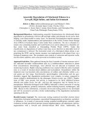
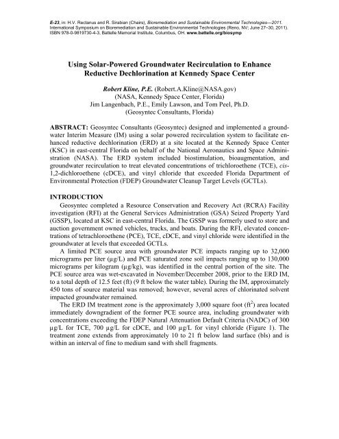
E-23, in: H.V. Rectanus and R. Sirabian (Chairs), Bioremediation and Sustainable Environmental Technologies—2011.International Symposium on Bioremediation and Sustainable Environmental Technologies (Reno, NV; June 27–30, 2011).ISBN 978-0-9819730-4-3, Battelle Memorial Institute, Columbus, OH. www.battelle.org/biosymp<strong>Using</strong> <strong>Solar</strong>-<strong>Powered</strong> <strong>Groundwater</strong> <strong>Recirculation</strong> <strong>to</strong> <strong>Enhance</strong>Reductive Dechlorination at Kennedy Space CenterRobert Kline, P.E. (Robert.A.Kline@NASA.gov)(NASA, Kennedy Space Center, Florida)Jim Langenbach, P.E., Emily Lawson, and Tom Peel, Ph.D.(Geosyntec Consultants, Florida)ABSTRACT: Geosyntec Consultants (Geosyntec) designed and implemented a groundwaterInterim Measure (IM) using a solar powered recirculation system <strong>to</strong> facilitate enhancedreductive dechlorination (ERD) at a site located at the Kennedy Space Center(KSC) in east-central Florida on behalf of the National Aeronautics and Space Administration(NASA). The ERD system included biostimulation, bioaugmentation, andgroundwater recirculation <strong>to</strong> treat elevated concentrations of trichloroethene (TCE), cis-1,2-dichloroethene (cDCE), and vinyl chloride that exceeded Florida Department ofEnvironmental Protection (FDEP) <strong>Groundwater</strong> Cleanup Target Levels (GCTLs).INTRODUCTIONGeosyntec completed a Resource Conservation and Recovery Act (RCRA) Facilityinvestigation (RFI) at the General Services Administration (GSA) Seized Property Yard(GSSP), located at KSC in east-central Florida. The GSSP was formerly used <strong>to</strong> s<strong>to</strong>re andauction government owned vehicles, trucks, and boats. During the RFI, elevated concentrationsof tetrachloroethene (PCE), TCE, cDCE, and vinyl chloride were identified in thegroundwater at levels that exceeded GCTLs.A limited PCE source area with groundwater PCE impacts ranging up <strong>to</strong> 32,000micrograms per liter (µg/L) and PCE saturated zone soil impacts ranging up <strong>to</strong> 130,000micrograms per kilogram (µg/kg), was identified in the central portion of the site. ThePCE source area was wet-excavated in November/December 2008, prior <strong>to</strong> the ERD IM,<strong>to</strong> a <strong>to</strong>tal depth of 12.5 feet (ft) (9 ft below the water table). During the IM, approximately450 <strong>to</strong>ns of source material was removed; however, several acres of chlorinated solventimpacted groundwater remained.The ERD IM treatment zone is the approximately 3,000 square foot (ft 2 ) area locatedimmediately downgradient of the former PCE source area, including groundwater withconcentrations exceeding the FDEP Natural Attenuation Default Criteria (NADC) of 300µg/L for TCE, 700 µg/L for cDCE, and 100 µg/L for vinyl chloride (Figure 1). Thetreatment zone extends from approximately 10 <strong>to</strong> 21 ft below land surface (bls) and iswithin an interval of fine <strong>to</strong> medium sand with shell fragments.
FIGURE 1. ERD IM treatment area.A variety of remedial technologies for the treatment of volatile organic compounds(VOCs) in the dissolved plume were screened against both RCRA corrective measurecriteria and USEPA’s Green Remediation Best Management Practices. Although severalstrategies were judged <strong>to</strong> meet the corrective measure goals, the bioremediation remedyalso aligned well with USEPA’s core elements of Green Remediation. The remedialstrategy selected was an enhanced reductive dechlorination (ERD) system which includedbiostimulation, bioaugmentation, and groundwater recirculation. <strong>Groundwater</strong> recirculationis accomplished using a solar powered extraction system, with an objective of enhancingmixing and the distribution of injected electron donor and microbial culturewithin the treatment zone.MATERIALS AND METHODSThe ERD remedy was implemented as an IM in August 2010 <strong>to</strong> address elevatedVOC concentrations in the treatment zone, an approximately 3,000 ft 2 area within theoverall dissolved plume. The objective of the IM is <strong>to</strong> reduce groundwater concentrationswithin the treatment zone (which represents the primary core of the overall dissolvedplume) <strong>to</strong> less than FDEP NADCs <strong>to</strong> facilitate natural attenuation of the overall plumewithin a reasonable timeframe.ERD was implemented through the delivery of emulsified oil, microbial culture andanaerobic chase water <strong>to</strong> a network of 46 direct-push technology (DPT) permanent injectionpoints with 5-ft screen intervals installed throughout the treatment zone. Electrondonor and microbial culture in situ mixing and distribution is aided by a solar-poweredgroundwater recirculation system. This system includes two extraction wells, each fitted
with a solar-powered submersible pump. Extracted groundwater is re-injected in<strong>to</strong> nineinjection wells oriented in three transects up-gradient and down-gradient of the extractionwells <strong>to</strong> maximize contact and distribution within the targeted treatment zone (Figure 2).FIGURE 2. ERD IM overall well layout.A performance moni<strong>to</strong>ring well network, the network of injection points, andgroundwater recirculation system (extraction wells, injection wells and piping system)were installed in August and September 2010. The performance moni<strong>to</strong>ring well networkwas installed <strong>to</strong> assess ERD progress within the treatment zone over time. The performancemoni<strong>to</strong>ring network includes six well clusters with shallow wells screened from 10<strong>to</strong> 15 ft bls and deeper wells screened from 16 <strong>to</strong> 21 ft bls. Three performance moni<strong>to</strong>ringwell clusters were located within the treatment zone (at worst-case distances betweeninjection points <strong>to</strong> avoid data bias). Three additional moni<strong>to</strong>ring well clusters providegeneral down-gradient and side-gradient moni<strong>to</strong>ring <strong>to</strong> document that the IM is not havinga negative impact on surrounding groundwater conditions (plume spreading).The network of DPT injection point clusters was installed <strong>to</strong> facilitate injection activitiesassociated with the ERD IM (Pho<strong>to</strong>graph 1). Permanent injection points will allowadditional injection activities in the future, if warranted. The network of points includes22 clusters (shallow injection points screened from 10 <strong>to</strong> 15 ft bls and deeper pointsscreened from 16 <strong>to</strong> 21 ft bls) and two shallow points (screened from 10 <strong>to</strong> 15 ft bls).Two groundwater extraction wells and nine groundwater injection wells were installedas part of the groundwater recirculation system associated with the ERD IM. The
extraction and injection wells were installedusing hollow stem auger drilling techniques.The extraction wells are located within thecenterline of the IM treatment zone. Theinjection and extraction wells are screenedfrom 11 <strong>to</strong> 21 ft bls. The injection wells areoriented in three transects located upgradient,downgradient, and between the extractionwells in order <strong>to</strong> create groundwater circulationcells enhancing the mixing and distributionof the electron donor and microbialculture.Baseline groundwater sampling was performedin August 2010. <strong>Groundwater</strong> samplescollected from the performance moni<strong>to</strong>ringwells and the two extraction wells were labora<strong>to</strong>ryanalyzed for VOCs by EnvironmentalProtection Agency (EPA) Method 8260B,Total Organic Carbon (TOC) by EPA Method415.1 and dissolved gases (methane, ethanePHOTOGRAPH 1. DPT injection pointinstallation.and ethene [MEE]) by EPA RSK SOP 147. Samples from moni<strong>to</strong>ring well clusters withinthe IM treatment zone were also labora<strong>to</strong>ry analyzed for Dehalococcoides (Dhc) and thevinyl chloride reductase gene (vcrA). All groundwater sampling activities include thecollection of field parameters: pH, temperature, conductivity, dissolved oxygen (DO),and oxidation-reduction potential (ORP).EOS ® , an emulsified oil consisting of 59.8% soybean oil, 4% lactic acid, 10.1%emulsifiers and preservatives, and a balance of water, was selected as the electron donorfor GSSP. KB-1 ® was selected as the microbial culture for injection within the treatmentzone. KB-1 ® is a naturally occurring, non-pathogenic microbial culture that contains Dhcwith the vcrA gene. A microbial culture was deemed necessary at GSSP based upon: (1) aseries of labora<strong>to</strong>ry treatability studies which documented dechlorination stall at vinylchloride unless a microbial culture was added, (2) the detection of low Dhc and absenceof vcrA in collected groundwater samples from the treatment zone (suggesting naturallyoccurring microorganisms capable of dechlorinating vinyl chloride were absent or presentat very low levels), and (3) the dissolved plume characteristics (downgradient plume islargely comprised of vinyl chloride).Electron donor and anaerobic water solution, microbial culture, and anaerobic chasewater were injected in<strong>to</strong> the injection points using an injection trailer. A <strong>to</strong>tal of sixdrums of EOS ® were injected within the treatment zone. The six drums of EOS ® werediluted 1:10 (by volume) with anaerobic water and evenly injected in<strong>to</strong> each of the 46injection points. Each injection point received approximately 70 gallons of diluted EOS ®solution (3,200 <strong>to</strong>tal gallons of solution <strong>to</strong> the 46 injection points). Prior <strong>to</strong> injection ofKB-1 ® , field parameters (pH, DO, and ORP) were collected from each injection point <strong>to</strong>verify that the aquifer was anaerobic and reducing. A <strong>to</strong>tal of 21.5 liters of KB-1 ® wasadded <strong>to</strong> the treatment zone, 0.5 liter in<strong>to</strong> 40 of the 46 injection points, and 0.25 liters in<strong>to</strong>six shallow injection points (Pho<strong>to</strong>graph 2). In order <strong>to</strong> obtain the desired initial radius of
influence (ROI) of 5 ft, approximately 665 gallons ofanaerobic chase water was injected in<strong>to</strong> each injectionpoint following the addition of the KB-1 ® . Anaerobicchase water was obtained from the two extraction wells.Each injection point received approximately 735 <strong>to</strong>talgallons of fluids (<strong>to</strong>tal treatment zone injection volume of33,800 gallons). During all injection activities, the injectionpressure was maintained at less than 20 pounds persquare inch (psi) <strong>to</strong> minimize the potential for shortcircuitingand/or daylighting of injected fluids. No daylightingof any fluids was observed during the performanceof injection activities.After baseline sampling and injection activities, thegroundwater recirculation system was piped from theextraction wells <strong>to</strong> the injection wells. The groundwaterrecirculation system consists of nine injection wells andtwo extraction wells completed with solar powered submersiblepumps. The groundwater recirculation systempumps groundwater from two extraction wells in<strong>to</strong> threeinjection well transects consisting of three injection wellseach. <strong>Groundwater</strong> is pumped from the extraction wellsusing solar powered pump kits (Pho<strong>to</strong>graph 3). The kitsinclude 27 inch by 42 inch solar panel(s) and submersibleRobison BL40Q quad pumps. To evaluate panel performance,one kit was purchased with one solar panel and onekit includes a two panel assembly. Each solar panel providesan estimated 75 Watts of solar power during peaksunlight hours. The pumps are designed <strong>to</strong> provide agroundwater flow of approximately 5 gallons per minute(gpm) during peak sunlight hours. Since the system wasdesigned <strong>to</strong> enhance groundwater movement and contact,continuous operation is not required; accordingly, thesystem only operates during sunlight hours.The ERD recirculation system was officially startedon 30 September 2010, following the completion of allinjection activities. Routine operation and maintenancevisits are conducted <strong>to</strong> confirm operation, record flow<strong>to</strong>talizer readings, and measure water levels within thetreatment zone.PHOTOGRAPH 2.KB-1 ® injection.PHOTOGRAPH 3.<strong>Solar</strong> panel system.RESULTS AND DISCUSSIONTo date, performance moni<strong>to</strong>ring has been conducted at one month, two months, fourmonths, and six months post EOS ® and KB-1 ® injection. <strong>Groundwater</strong> samples collectedfrom the performance moni<strong>to</strong>ring wells and extraction wells were labora<strong>to</strong>ry analyzed forVOCs by EPA Method 8260. <strong>Groundwater</strong> samples collected from the three performancemoni<strong>to</strong>ring well clusters within the IM treatment zone and from the two extraction wells
were also analyzed for TOC and MEE. Samples collected from the central performancemoni<strong>to</strong>ring well cluster within the IM treatment zone were also analyzed for Dhc andvcrA.Performance moni<strong>to</strong>ring and aquifer suitability for ongoing reductive dechlorinationwere evaluated using the following data: (1) field parameters; (2) presence and distributionof VOCs; and (3) geochemical and microbial parameters. The following summarizesthe findings.Field parameters were collected <strong>to</strong> evaluate the ongoing suitability of the aquifer forreductive dechlorination. Optimal conditions include a neutral pH (near 7 standard units),negative ORP and low DO (generally accepted as less than 0.5 mg/L). The month sixaverage pH of 7.1 standard units, average DO of 0.31 mg/L and negative ORP (-94 milliVolts)all indicate a favorable environment for bioremediation <strong>to</strong> occur.VOC results from baseline <strong>to</strong> month six show significant reduction of VOCs. Asummary with respect <strong>to</strong> IM objectives follows:• TCE was reduced from a maximum of 769 µg/L <strong>to</strong> less than the GCTL of 3 µ/Lin all performance moni<strong>to</strong>ring wells and has exceeded the IM objective;• cDCE was reduced from a maximum of 1,980 µg/L <strong>to</strong> a maximum of 194 µ/L,and has exceeded the IM objectives; and• Overall vinyl chloride has decreased with concentrations exceeding the IMNADC objective in only one performance moni<strong>to</strong>ring well; concentration increaseswith a follow-up decrease has been observed at select locations suggestsERD is ongoing.Reductive dechlorinating bacteria thrive in similar environmental conditions <strong>to</strong> methanogens;therefore, methane production is a good indica<strong>to</strong>r that favorable conditions exist forreductive dechlorination. Methane concentrations have increased from an average of1,304 µg/L during baseline sampling <strong>to</strong> 5,618 µg/L in month six. The presence of etheneat a maximum of 182 µg/L (generally less than 5 µg/L prior <strong>to</strong> implementation) indicatesthat complete dechlorination is occurring within the IM treatment zone. The averageconcentration of TOC more than doubled <strong>to</strong> an average of 71 mg/L in month one, and hasslowly decreased <strong>to</strong> 49 mg/L in month six (approximately 50 percent above background),indicating that the electron donor is being effectively distributed throughout the treatmentzone and is currently being utilized by the microbial population.Within the treatment zone, Dhc concentrations increased one order of magnitude inmoni<strong>to</strong>ring well MW0058 (from 10 6 <strong>to</strong> 10 7 gene copies/L) and two orders of magnitudein MW0059 (from 10 5 <strong>to</strong> 10 7 gene copies/L) from baseline <strong>to</strong> Month 6. vcrA was notdetected in any of the six baseline samples above the detection limit of 10 3 gene copies/L.Month six performance moni<strong>to</strong>ring samples revealed vcrA concentrations of 10 7 genecopies/L in the two moni<strong>to</strong>ring wells sampled, MW0058 and MW0059. The increasingtrends in Dhc and significant increase/detections of vcrA suggest that reductive dechlorinationis occurring and that a microbial population capable of reducing vinyl chloride <strong>to</strong>ethene has been established within the treatment zone.
GRAPHS. VOC concentrations through month 6 in six moni<strong>to</strong>ring wells locatedwithin the treatment zone.
The operating solar-powered groundwater recirculation system recirculated 660,000gallons of groundwater during the first six months of operation representing more than10 treatment zone pore volumes. During sunlight hours, individual extraction wellgroundwater pumping rates have ranged from 1.9 <strong>to</strong> 7.0 gallons per minute. Collectedgroundwater level measurements have documented that the operating groundwater recirculationsystem is achieving an objective of creating zones of enhanced contact andgroundwater mixing, with groundwater elevation con<strong>to</strong>urs similar <strong>to</strong> flow model predictedcon<strong>to</strong>urs.CONCLUSIONSThe effectiveness of the ongoing ERD IM was evaluated via the sampling of performancemoni<strong>to</strong>ring wells located in and around the IM treatment zone and labora<strong>to</strong>ryanalysis for VOCs, geochemical parameters, and biological indica<strong>to</strong>rs. All indicationspoint <strong>to</strong>ward effective in situ treatment of CVOC impacted groundwater within the treatmentzone. After only six months of operation TCE and DCE concentrations are belowcorrective action objectives and vinyl chloride concentrations are rapidly approachingobjectives.REFERENCESNational Aeronautics and Space Administration. April 2008. GSA Seized PropertySWMU No. 095 RCRA Facility Investigation Report and Corrective Measures StudyWork Plan (Revision 1), Kennedy Space Center, Florida. KSC-TA-8976.National Aeronautics and Space Administration. March 2010a. GSA Seized PropertySWMU 095 RCRA Facility Investigation Addendum (Revision 0), Kennedy SpaceCenter, Florida. KSC-TA-9425.National Aeronautics and Space Administration. May 2010b. GSA Seized PropertySWMU 095 <strong>Enhance</strong>d Reductive Dechlorination Interim Measures Work Plan (Revision0), Kennedy Space Center, Florida. KSC-TA-11237.National Aeronautics and Space Administration. January 2011. GSA Seized PropertySWMU 095 <strong>Enhance</strong>d Reductive Dechlorination Interim Measures ImplementationReport (Revision 0), Kennedy Space Center, Florida. KSC-TA-11422.
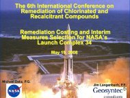
Kennedy Space CenterCenter Operations Direc<strong>to</strong>rateMedical & Environmental Management Division<strong>Using</strong> <strong>Solar</strong> <strong>Powered</strong> <strong>Groundwater</strong><strong>Recirculation</strong> <strong>to</strong> <strong>Enhance</strong> ReductiveDechlorination at Kennedy SpaceCenterPresented <strong>to</strong>:Battelle Bioremediation and Sustainable EnvironmentalTechnologies SymposiumBy:Robert Kline, P.E. NASA, Kennedy Space Center, FloridaJune 28, 2011Reno, Nevada
Kennedy Space CenterCenter Operations Direc<strong>to</strong>ratePresentation OutlineMedical & Environmental Management Division♦ Site His<strong>to</strong>ry and Background♦ Assessment and Supporting Actions Overview♦ Comparison <strong>to</strong> Core Elements of Green Remediation♦ <strong>Enhance</strong>d Reductive Dechlorination (ERD) InterimMeasure (IM) Remedy♦ ERD IM Results♦ Conclusions2
Kennedy Space CenterCenter Operations Direc<strong>to</strong>rateSite His<strong>to</strong>ryMedical & Environmental Management Division♦ GSA Seized Property Yard(site) is a ~6 acre propertywithin the Industrial Areaof Kennedy Space Center,Florida♦ Formerly used <strong>to</strong> s<strong>to</strong>re andauction seized vehicles♦ Six <strong>to</strong> seven administrativetrailers have beenused/s<strong>to</strong>red on site in thepast3
Kennedy Space CenterCenter Operations Direc<strong>to</strong>rate♦ RFI completed in 2008♦ Detailed DPTassessment (over 100locations) and followupmicro-wellsrevealed:‣ 1,650 ft dissolved plume(primarily vinyl chloride)‣ PCE source area (1 and 100 and 1,000 µg/Lvinyl chloridePCE SourceArea4
Kennedy Space CenterCenter Operations Direc<strong>to</strong>rateSource Area Assessment/InterimMeasure (IM)Medical & Environmental Management Division♦ PCE source area identified from 8 <strong>to</strong>12 ft below grade (water table at 4 ft):‣ PCE groundwater concentrations up <strong>to</strong>32,000 µg/L‣ Saturated soil PCE up <strong>to</strong> 130,000 µg/kg‣ Limited PCE footprint laterally andvertically based upon DPT investigation♦ Wet excavation IM <strong>to</strong> 13 ft belowgrade in December 2008:‣ 442 <strong>to</strong>ns of PCE impacted soils removed‣ electron donor addition <strong>to</strong> open hole♦ Source area addressed: Max PCE3 ug/LPCE >3,000 ug/LPCE >30,000 ug/LPCE >300 ug/L5
Kennedy Space CenterCenter Operations Direc<strong>to</strong>rateERD <strong>Groundwater</strong> IMMedical & Environmental Management Division♦ Purpose: Remediate groundwater downgradient ofthe former source area with elevated VOCconcentrations:‣ Approximately 3,000 ft 2 area‣ VOCs focused in 10-21 ft below land surface (bls) depthinterval‣ Screening considered USEPA Green remediation BMPs‣ Bench-scale treatability testing performed‣ ERD with biostimulation, bioaugmentation and integration ofsolar-powered groundwater recirculation selected♦ Corrective Action Objective (CAO): Reduce VOCconcentrations in the IM treatment zone <strong>to</strong> less than300 µg/L TCE, 700 µg/L cDCE, and 100 µg/L vinylchloride6
Kennedy Space CenterCenter Operations Direc<strong>to</strong>rateERD IM Compared <strong>to</strong> GreenRemediation Core ElementsMedical & Environmental Management Division♦ Energy:‣ Limited construction energy use‣ <strong>Solar</strong> system for groundwater recirculation‣ Minimal O&M♦ Air Emissions:‣ In Situ treatment technology‣ Lower CO 2 operational emissions than air sparge and P&T alternativesconsidered♦ Materials Management/Waste Reduction:‣ No ongoing water use‣ Reusable solar pumps/panels‣ Majority of drilling work via DPT (limited IDW generation)‣ Minimal waste stream associated with cleanup efforts‣ Approval <strong>to</strong> place sampling water in closed-loop recirculation system (no IDW)‣ Limited impacts <strong>to</strong> land and ecosystem associated with system/construction7
Kennedy Space CenterCenter Operations Direc<strong>to</strong>rateIM ActivitiesWell InstallationsMedical & Environmental Management Division♦ Field activities conducted August 2010♦ Performance Moni<strong>to</strong>ring Wells (DPT Installed)‣ Six well clusters (pre-packed screen 10-15 ft blsand 16-21 ft bls)‣ Three clusters down centerline of TreatmentZone, two side-gradient, and one down-gradient♦ Injection Points (DPT Installed)‣ 22 clusters (screened 10-15 ft bls and 16-21 ftbls)‣ 2 individual 16-21 ft bls points♦ Two, 5-inch diameter extraction wells(screened from 11-21 ft bls)♦ Nine, 4-inch diameter injection wells (screenedfrom 11-21 ft bls)8
Kennedy Space CenterCenter Operations Direc<strong>to</strong>rate<strong>Groundwater</strong> <strong>Recirculation</strong>System LayoutIM LayoutMedical & Environmental Management DivisionUndergroundPiping (typ)Conceptual <strong>Solar</strong> SystemExtraction WellExtraction WellPermanent Injection Pt (typ)Moni<strong>to</strong>ring WellCluster (typ)<strong>Recirculation</strong> InjectionWell (typ)9
Kennedy Space CenterCenter Operations Direc<strong>to</strong>rate<strong>Recirculation</strong> SystemInstallationMedical & Environmental Management DivisionInstallation ofthe <strong>Solar</strong><strong>Powered</strong><strong>Groundwater</strong><strong>Recirculation</strong>System10
Kennedy Space CenterCenter Operations Direc<strong>to</strong>rateIM ActivitiesEmulsified Oil Injection• Injection of 1:10 diluted emulsified oil solution– Six drums of electron donor injected September 2010Medical & Environmental Management Division– Diluted e-donor (60 percent solution) 1:10 with site groundwater andinjected 45 <strong>to</strong> 120 (average of 72) gallons per injection point11
Kennedy Space CenterCenter Operations Direc<strong>to</strong>rateIM Injection ActivitiesKB-1 Injection♦ Confirmed anaerobic, reducing conditions♦ Injection of KB-1 Microbial Culture‣ 20 L of culture‣ 500 mL in<strong>to</strong> 40 of the 46 injection pointsMedical & Environmental Management Division‣ Six shallow injection points received 250 mL of culture♦ 665 <strong>to</strong> 805 gallons of chase water per injectionpoint12
Kennedy Space CenterCenter Operations Direc<strong>to</strong>rate♦ Geochemistry<strong>Groundwater</strong> ERD ResultsMedical & Environmental Management Division‣ Baseline average methane 1,304 µg/L, month 6 average methane5,618 µg/L‣ Ethene increase from
Kennedy Space CenterCenter Operations Direc<strong>to</strong>rate<strong>Groundwater</strong> ERD ResultsMedical & Environmental Management DivisionDhc and vcrA Concentration Trends14
Kennedy Space CenterCenter Operations Direc<strong>to</strong>rate<strong>Groundwater</strong> ERD ResultsMedical & Environmental Management DivisionVOC Results – Trend Graphs(centerline upgradient cluster MW0056/MW0057)15
Kennedy Space CenterCenter Operations Direc<strong>to</strong>rate<strong>Groundwater</strong> ERD ResultsMedical & Environmental Management DivisionVOC Results – Trend Graphs(centerline central cluster MW0058/MW0059)16
Kennedy Space CenterCenter Operations Direc<strong>to</strong>rate<strong>Groundwater</strong> ERD ResultsMedical & Environmental Management DivisionVOC Results – Trend Graphs(centerline downgradient cluster MW0064/MW0065)17
Kennedy Space CenterCenter Operations Direc<strong>to</strong>rate<strong>Groundwater</strong> ERD ResultsMedical & Environmental Management DivisionVOC Results – Trend Graphs(sidegradient cluster MW0060/MW0061)18
Kennedy Space CenterCenter Operations Direc<strong>to</strong>rate<strong>Groundwater</strong> ERD ResultsMedical & Environmental Management DivisionVOC Results – Trend Graphs(sidegradient cluster MW0062/MW0063)19
Kennedy Space CenterCenter Operations Direc<strong>to</strong>rate<strong>Groundwater</strong> ERD ResultsMedical & Environmental Management DivisionVOC Results – Trend Graphs(downgradient cluster MW0066/MW0067)20
Kennedy Space CenterCenter Operations Direc<strong>to</strong>rate<strong>Groundwater</strong> ERD ResultsMedical & Environmental Management DivisionVOC Results – Trend Graphs(centerline extraction wells EW0001/EW0002)21
Kennedy Space CenterCenter Operations Direc<strong>to</strong>rate<strong>Solar</strong> System <strong>Recirculation</strong>SummaryMedical & Environmental Management Division♦ Pumping rates from 1.9 <strong>to</strong> 7.0 gpm per extraction well♦ 936,000 gallons recirculated during 9 months of operation(over 15 treatment zone pore volumes)♦ <strong>Groundwater</strong> elevation moni<strong>to</strong>ring documented effectivedrawdown, mounding and recirculation22
Kennedy Space CenterCenter Operations Direc<strong>to</strong>rateConclusionsMedical & Environmental Management Division♦ Corrective Action Objectives (CAOs) achieved within 9months within treatment zone♦ Target treatment area of 3,000 ft 2 , actual area treatedexceeds 5,000 ft 2♦ Integrated solar recirculation system:‣ Provides adequate power at a cost less than dedicated electricalservice ($4k for panel/pump/hardware per location)‣ Quick installation/mobilization and demobilization‣ Reusable system/components (reuse plans in the works)♦ Total project costs of $300K (capital costs, moni<strong>to</strong>ring,reporting for 9 months)♦ Flexible approach which can be expanded downgradient ordeployed at other nearby sites23
Kennedy Space CenterCenter Operations Direc<strong>to</strong>rateThank You!Medical & Environmental Management DivisionAcknowledgements:♦♦♦Jim Langenbach, PE, Geosyntec ConsultantsTom Peel, PhD, Geosyntec ConsultantsEmily Lawson, Geosyntec ConsultantsQuestions?24