john f. kennedy space center brevard county, florida - Environmental ...
john f. kennedy space center brevard county, florida - Environmental ...
john f. kennedy space center brevard county, florida - Environmental ...

You also want an ePaper? Increase the reach of your titles
YUMPU automatically turns print PDFs into web optimized ePapers that Google loves.
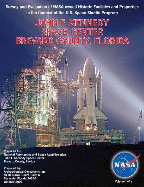
Survey and Evaluation of NASA-owned Historic Facilities and Properties<br />
In the Context of the U.S. Space Shuttle Program<br />
JOHN F. KENNEDY<br />
SPACE CENTER<br />
BREVARD COUNTY, FLORIDA<br />
Prepared for:<br />
National Aeronautics and Space Administration<br />
John F. Kennedy Space Center<br />
Brevard County, Florida<br />
Prepared by:<br />
Archaeological Consultants, Inc.<br />
8110 Blaikie Court, Suite A<br />
Sarasota, Florida 34240<br />
October 2007<br />
Volume I of V
NASA-WIDE SURVEY AND EVALUATION<br />
OF HISTORIC FACILITIES AND PROPERTIES<br />
IN THE CONTEXT OF THE<br />
U.S. SPACE SHUTTLE PROGRAM<br />
JOHN F. KENNEDY SPACE CENTER,<br />
BREVARD COUNTY, FLORIDA<br />
Prepared for:<br />
National Aeronautics and Space Administration<br />
John F. Kennedy Space Center<br />
Brevard County, Florida<br />
By:<br />
Archaeological Consultants, Inc.<br />
8110 Blaikie Court, Suite A<br />
Sarasota, Florida 34240<br />
Joan Deming - Project Manager<br />
Patricia Slovinac - Architectural Historian<br />
October 2007
“The first great era of <strong>space</strong> is over. The second is about to begin. It will<br />
come into its own with the Shuttle, the heart of our new <strong>space</strong> transportation<br />
system. The Shuttle program has been a very large effort. More than 5,000<br />
companies and nearly 50,000 Americans all across the country have worked<br />
in designing, manufacturing, and testing the Shuttle. I congratulate the<br />
scientists, engineers, skilled workers, and others that have contributed<br />
directly to this success.”<br />
President Jimmy Carter, March 24, 1979, in recognition of the arrival of Columbia at the<br />
Kennedy Space Center
Space Shuttle Program Historic Properties<br />
NASA Kennedy Space Center<br />
EXECUTIVE SUMMARY<br />
The National Aeronautics and Space Administration (NASA) has undertaken a historical<br />
survey and evaluation of all NASA-owned facilities and properties (real property assets)<br />
to determine their eligibility for listing in the National Register of Historic Places<br />
(NRHP) in the context of the U.S. Space Shuttle Program (1969-2010), which has been<br />
slated for retirement in the year 2010. In February of 2006, a Shuttle Transition Historic<br />
Preservation Working Group (HPWG) was formed which included the Historic<br />
Preservation Officers (HPOs) for all NASA Centers. This group, tasked with<br />
implementation of the historic facilities survey, is coordinating its efforts with the Shuttle<br />
Transition <strong>Environmental</strong> Support Team. The HPWG drafted a set of standard criteria for<br />
the evaluation of Shuttle program-related properties at all NASA Centers.<br />
This report, prepared on behalf of NASA’s John F. Kennedy Space Center (KSC) in<br />
Brevard County, Florida, was conducted in compliance with Section 110 of the National<br />
Historic Preservation Act (NHPA) of 1966 (Public Law 89-665), as amended; the<br />
National <strong>Environmental</strong> Policy Act (NEPA) of 1969 (Public Law 91-190); Executive<br />
Order (EO) 11593: Protection and Enhancement of the Cultural Environment; EO 13287,<br />
Preserve America; and other relevant legislation.<br />
The evaluation of NASA KSC facilities focused on 112 properties which were<br />
determined, preliminarily, to have supported the Space Shuttle Program. As a result of<br />
research and field survey, 26 assets were considered to individually meet the criteria of<br />
eligibility for listing in the NRHP within the context of this study. Included in the total 26<br />
assets are six NRHP-listed historic properties, the Vehicle Assembly Building (VAB),<br />
Launch Control Center (LCC), Crawlerway, two Crawler Transporters, and the Press<br />
Site: Clock and Flag Pole. Twenty additional assets were newly assessed as individually<br />
NRHP-eligible. These include Launch Complex 39: Pad A, Launch Complex 39: Pad B,<br />
the Shuttle Landing Facility Runway, the Landing Aids Control Building, the Mate-<br />
Demate Device, the Orbiter Processing Facility (High Bays 1 and 2), the Orbiter<br />
Processing Facility High Bay 3, the Thermal Protection System Facility, the<br />
Rotation/Processing Facility, the SRB Manufacturing Building, the Parachute<br />
Refurbishment Facility, the Canister Rotation Facility, the Hypergol Module Processing<br />
North, two Payload Canisters, the two Retrieval Ships Freedom Star and Liberty Star,<br />
and the three Mobile Launcher Platforms.<br />
Two previously listed historic districts, the Launch Complex 39: Pad A Historic District<br />
and the Launch Complex 39: Pad B Historic District, originally listed for their<br />
exceptional significance in the context of the Apollo Program, were also assessed as<br />
significant within the context of the Space Shuttle Program. Each district contains 21<br />
contributing resources of which one is individually eligible and 20 are contributing but<br />
not individually eligible. In addition, four new historic districts were identified. The<br />
Shuttle Landing Facility Area Historic District contains three properties which are all<br />
both individually eligible and contributing; the Orbiter Processing Historic District<br />
includes three properties which are both individually eligible and contributing; the Solid<br />
October 2007<br />
ii<br />
Archaeological Consultants, Inc.
Space Shuttle Program Historic Properties<br />
NASA Kennedy Space Center<br />
Rocket Booster Disassembly and Refurbishment Complex Historic District contains no<br />
individually eligible properties but 9 contributing resources; and the Hypergolic<br />
Maintenance and Checkout Area Historic District contains one individually eligible<br />
property and one contributing resource.<br />
In conclusion, of the total 112 assets identified and evaluated at the KSC, 76 are NRHPlisted<br />
or eligible properties, including 26 individually listed or eligible properties and 50<br />
which are contributing to a historic district, but which are not considered individually<br />
eligible. Of the 76 significant assets, 36 were previously determined NRHP-eligible, and<br />
40 were newly evaluated. Thirty-six assets are evaluated as ineligible for listing in the<br />
NRHP, either individually or as part of a historic district.<br />
October 2007<br />
iii<br />
Archaeological Consultants, Inc.
Space Shuttle Program Historic Properties<br />
NASA Kennedy Space Center<br />
TABLE OF CONTENTS<br />
Page<br />
1.0 INTRODUCTION ............................................................................................. 1-1<br />
1.1 Purpose..................................................................................................... 1-1<br />
1.2 Project Summary and Objectives............................................................. 1-1<br />
1.3 KSC Location and Land Acquisitions ..................................................... 1-2<br />
1.4 Acknowledgements.................................................................................. 1-7<br />
2.0 METHODOLOGY ............................................................................................ 2-1<br />
2.1 National Register Criteria for Evaluation ................................................ 2-1<br />
2.2 The Space Shuttle Program: NRHP Criteria for Evaluation and Criteria<br />
Considerations ......................................................................................... 2-2<br />
2.2.1 NRHP Criteria..............................................................................2-2<br />
2.2.2 Criteria Considerations ................................................................2-3<br />
2.2.3 Integrity........................................................................................ 2-4<br />
2.3 National Register Historic Districts......................................................... 2-4<br />
2.4 Property Types......................................................................................... 2-5<br />
2.5 Research Methods.................................................................................. 2-10<br />
3.0 HISTORICAL CONTEXT ............................................................................... 3-1<br />
3.1 Prologue................................................................................................... 3-1<br />
3.2 Early Visions and Concepts..................................................................... 3-1<br />
3.3 Feasibility and Definition Studies............................................................ 3-3<br />
3.4 Shuttle Development and Testing............................................................ 3-4<br />
3.4.1 Contractor Awards.......................................................................3-5<br />
3.4.2 The Orbiter Enterprise.................................................................3-6<br />
3.4.3 Approach and Landing Test (ALT) Program............................... 3-6<br />
3.4.4 Orbital Test Flights: 1981-1982................................................... 3-8<br />
3.5 Operational Flights: 1982-1986............................................................... 3-9<br />
3.5.1 The Challenger Accident and Aftermath................................... 3-10<br />
3.5.2 Return to Flight: 1988 to 2002................................................... 3-12<br />
3.5.3 The Columbia Accident and Aftermath: 2003-Present..............3-13<br />
4.0 NASA KSC AND THE U.S. SPACE SHUTTLE PROGRAM...................... 4-1<br />
4.1 Historical Background ............................................................................. 4-1<br />
4.2 Apollo Program: 1961-1975 ................................................................... 4-1<br />
4.3 Facility Modifications and New Construction......................................... 4-3<br />
4.3.1 Modification of Major Facilities.................................................. 4-4<br />
4.3.2 New Construction ........................................................................ 4-7<br />
4.3.3 Modifications in the Post-Challenger Accident Period.............4-10<br />
4.4 General Process Flow ............................................................................ 4-10<br />
4.5 Missions and Payloads........................................................................... 4-13<br />
October 2007<br />
iv<br />
Archaeological Consultants, Inc.
Space Shuttle Program Historic Properties<br />
NASA Kennedy Space Center<br />
TABLE OF CONTENTS<br />
Page<br />
5.0 PREVIOUS INVESTIGATIONS..................................................................... 5-1<br />
5.1 The LC 39 Site......................................................................................... 5-1<br />
5.2 LC 39 Site Reassessment......................................................................... 5-1<br />
5.3 Survey and Evaluation of NASA-owned Facilities Within CCAFS ....... 5-2<br />
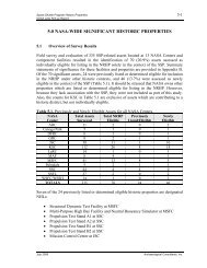
6.0 SURVEY RESULTS.......................................................................................... 6-1<br />
6.1 Summary of Survey Results .................................................................... 6-1<br />
6.2 NRHP- listed and Eligible Properties ...................................................... 6-7<br />
6.2.1 Vehicle Assembly Building (VAB) (8BR1684)..........................6-7<br />
6.2.2 Launch Control Center (LCC) (8BR1685) .................................. 6-9<br />
6.2.3 Crawler Transporters (8BR1688) ..............................................6-11<br />
6.2.4 Crawlerway (8BR1688).............................................................6-12<br />
6.2.5 The Press Site: Clock and Flag Pole (8BR1690).......................6-13<br />
6.2.6 Launch Complex (LC) 39: Pad A Historic District (8BR1686) 6-14<br />
6.2.7 Launch Complex 39: Pad A (8BR1995)....................................6-16<br />
6.2.8 Launch Complex (LC) 39: Pad B Historic District (8BR1687) 6-18<br />
6.2.9 Launch Complex 39: Pad B (8BR2010) ....................................6-20<br />
6.2.10 Shuttle Landing Facility Area Historic District (8BR1986)......6-21<br />
6.2.11 SLF (Runway) (8BR1987).........................................................6-23<br />
6.2.12 Landing Aids Control Building (LACB) (8BR1988) ................6-24<br />
6.2.13 Mate-Demate Device (MDD) (8BR1989) .................................6-25<br />
6.2.14 Orbiter Processing Historic District (8BR1990)........................ 6-27<br />
6.2.15 Orbiter Processing Facility (OPF) High Bays 1 and 2<br />
(8BR1991)..................................................................................6-28<br />
6.2.16 Orbiter Processing Facility High Bay 3 (OPF-3) (8BR1992).... 6-30<br />
6.2.17 Thermal Protection System Facility (TPSF) (8BR1994)...........6-33<br />
6.2.18 Solid Rocket Booster (SRB) Disassembly and Refurbishment<br />
Complex Historic District 8BR1996) ........................................6-35<br />
6.2.19 Rotation/Processing Building (8BR1997) .................................6-37<br />
6.2.20 SRB Assembly and Refurbishment (ARF) Manufacturing<br />
Building (8BR1998)...................................................................6-38<br />
6.2.21 Parachute Refurbishment Facility (PRF) (8BR2014)................6-40<br />
6.2.22 Canister Rotation Facility (CRF) (8BR2016)............................6-42<br />
6.2.23 Orbiter Payload Canisters (8BR2017) .......................................6-44<br />
6.2.24 Hypergolic Maintenance and Checkout Area (HMCA)<br />
Historic District 8BR2015)........................................................6-45<br />
6.2.25 Hypergol Module Processing (HMP) (North) (8BR1993) ........6-47<br />
6.2.26 Retrieval Ships LibertyStar (8BR2019) and Freedom Star<br />
(8BR2020)..................................................................................6-48<br />
6.2.27 Mobile Launcher Platforms (MLP) (8BR2021) ........................6-50<br />
6.3 Non-eligible Facilities and Properties.................................................... 6-52<br />
October 2007<br />
v<br />
Archaeological Consultants, Inc.
Space Shuttle Program Historic Properties<br />
NASA Kennedy Space Center<br />
TABLE OF CONTENTS<br />
Page<br />
7.0 CONCLUSIONS................................................................................................ 7-1<br />
7.1 Overview of Survey Results .................................................................... 7-1<br />
7.2 Individual NRHP Listed and Eligible Facilities and Properties .............. 7-1<br />
7.3 NRHP Listed and Eligible Historic Districts........................................... 7-6<br />
8.0 REFERENCES AND BIBLIOGRAPHY ........................................................ 8-1<br />
APPENDICES<br />
APPENDIX A: Space Shuttle Program Milestones (Volume I)<br />
APPENDIX B: Real Property List (Volume I)<br />
APPENDIX C: Facility Data Sheets (Volume I)<br />
APPENDIX D: NRHP Nomination Forms (Volumes II and III)<br />
APPENDIX E: Florida Master Site File Forms (Volumes IV and V)<br />
APPENDIX F: Survey Log Sheet (Volume I)<br />
APPENDIX G: Qualifications of Key Personnel (Volume I)<br />
October 2007<br />
vi<br />
Archaeological Consultants, Inc.
Space Shuttle Program Historic Properties<br />
NASA Kennedy Space Center<br />
LIST OF FIGURES AND TABLES AND PHOTOGRAPHS<br />
Figure<br />
Page<br />
Figure 1.1. Location of the Kennedy Space Center in Florida......................................1-3<br />
Figure 1.2. Kennedy Space Center Operational Area, Brevard County........................1-5<br />
Figure 4.1. NASA KSC Space Shuttle Program Standard Work Flow.......................4-12<br />
Table<br />
Table 1.1. List of Key Informants for Facilities Surveyed. .........................................1-7<br />
Table 3.1. Orbital Flight Tests. ....................................................................................3-9<br />
Table 4.1. NASA-owned SSP-related facilities, by decade of construction.............. 4-10<br />
Table 4.2. Tabulation of Space Shuttle Missions, 1981 through 2006. .....................4-13<br />
Table 4.3. Launch and Landing Data for Space Shuttle Missions, 1981-2006..........4-14<br />
Table 6.1. List of Surveyed Assets at NASA KSC...................................................... 6-2<br />
Table 7.1.<br />
Table 7.2.<br />
NASA KSC assets by property type: individually NRHP-listed and<br />
eligible resources. .......................................................................................7-2<br />
NASA KSC assets by property type: contributing resources (not<br />
individually eligible) within listed and eligible historic districts................ 7-3<br />
Photo<br />
Photo 1.1. Aerial view of the KSC Industrial Area, 1975............................................1-4<br />
Photo 1.2. Aerial view of the VAB and Launch Complex 39 Areas. ..........................1-6<br />
Photo 1.3. Aerial view of the VAB Area. ....................................................................1-6<br />
Photo 3.1.<br />
Photo 3.2.<br />
Enterprise and NASA 747 Shuttle Carrier Aircraft during the second<br />
free flight of the Approach and Landing Test program. .............................3-7<br />
The April 12, 1981 launch of STS-1...........................................................3-8<br />
Photo 3.3. Endeavour (OV-105) roll-out at Palmdale, California, May 6, 1991.......3-11<br />
October 2007<br />
vii<br />
Archaeological Consultants, Inc.
Space Shuttle Program Historic Properties<br />
NASA Kennedy Space Center<br />
Photo<br />
LIST OF FIGURES AND TABLES AND PHOTOGRAPHS<br />
Photo 3.4.<br />
Photo 6.1.<br />
Photo 6.2.<br />
Photo 6.3.<br />
Photo 6.4.<br />
The International Space Station in orbit, taken from Endeavour<br />
(STS-97) prior to docking, December 1, 2000. ........................................3-13<br />
Vehicle Assembly Building, south elevation..............................................6-7<br />
Space Shuttle vehicle in VAB.....................................................................6-8<br />
Launch Control Center, looking south........................................................6-9<br />
Crawler Transporter..................................................................................6-11<br />
Photo 6.5. Space Shuttle Atlantis en route to VAB, 2001..........................................6-12<br />
Photo 6.6. Press Site: Clock and Flag Pole. ...............................................................6-13<br />
Photo 6.7. Aerial view of LC39A, 1984. ...................................................................6-14<br />
Photo 6.8. Aerial view of Space Shuttle Discovery at LC 39A, 2000. ...................... 6-16<br />
Photo 6.9. Space Shuttle Atlantis arriving at LC 39B for simulation testing, 1986...6-18<br />
Photo 6.10. STS-112, Space Shuttle Atlantis, surrounded by RSS, at LC 39B, 2002. 6-20<br />
Photo 6.11. Aerial view of the SLF, August 1998. ......................................................6-21<br />
Photo 6.12. Shuttle Landing Facility Area, looking south...........................................6-22<br />
Photo 6.13. SLF Runway, looking north......................................................................6-23<br />
Photo 6.14. Landing Aids Control Building, control room looking southwest. ..........6-24<br />
Photo 6.15. Mate-Demate Device, south and west elevations. ....................................6-25<br />
Photo 6.16. Orbiter Processing Facilities, looking east................................................6-27<br />
Photo 6.17. Orbiter Processing Facility (High Bays 1 and 2), north and east<br />
elevations. .................................................................................................6-28<br />
Photo 6.18. Orbiter Processing Facility High Bay 1 interior, looking southwest........6-29<br />
Photo 6.19. Orbiter Processing Facility High Bay 3, south and west elevations.........6-30<br />
October 2007<br />
viii<br />
Archaeological Consultants, Inc.
Space Shuttle Program Historic Properties<br />
NASA Kennedy Space Center<br />
Photo<br />
LIST OF FIGURES AND TABLES AND PHOTOGRAPHS<br />
Photo 6.20. Orbiter Processing Facility High Bay 3, second level, looking northeast.6-31<br />
Photo 6.21. Space Shuttle Main Engine Facility at OPF High Bay 3, vertical stand...6-32<br />
Photo 6.22. Thermal Protection System Facility, south and east elevations................ 6-33<br />
Photo 6.23. Thermal Protection System Facility, sewing area.....................................6-34<br />
Photo 6.24. Thermal Protection System Facility, heat cleaning room.........................6-34<br />
Photo 6.25. Aerial view of the SRB Disassembly and Refurbishment Complex,<br />
July 1981...................................................................................................6-35<br />
Photo 6.26. Hangar AF, east elevation.........................................................................6-36<br />
Photo 6.27. Rotation/Processing Building, east elevation. ..........................................6-37<br />
Photo 6.28. Rotation/Processing Building, interior looking west................................6-37<br />
Photo 6.29. Rotation/Processing Building, north work area........................................6-38<br />
Photo 6.30. SRB ARF Manufacturing Building, north and west elevations................6-39<br />
Photo 6.31. SRB ARF, lifting crane.............................................................................6-39<br />
Photo 6.32. SRB ARF, paint applicator. ......................................................................6-40<br />
Photo 6.33. Parachute Refurbishment Facility, south elevation. .................................6-40<br />
Photo 6.34. Parachute Refurbishment Facility, sewing area........................................6-41<br />
Photo 6.35. Parachute Refurbishment Facility, work area...........................................6-41<br />
Photo 6.36. Canister Rotation Facility, south and east elevations. ..............................6-43<br />
Photo 6.37. Canister Rotation Facility, clean room interior, looking east. ..................6-43<br />
Photo 6.38. Canister Rotation Facility, interior to southeast. ......................................6-44<br />
Photo 6.39. Orbiter Payload Canister on Canister Transporter in the Space Shuttle<br />
Processing Facility....................................................................................6-45<br />
October 2007<br />
ix<br />
Archaeological Consultants, Inc.
Space Shuttle Program Historic Properties<br />
NASA Kennedy Space Center<br />
Photo<br />
LIST OF FIGURES AND TABLES AND PHOTOGRAPHS<br />
Photo 6.40. Hypergolic Maintenance and Checkout Area Historic District, looking<br />
northwest...................................................................................................6-46<br />
Photo 6.41. Hypergol Module Processing (North) Facility, south elevation. ..............6-47<br />
Photo 6.42. Retrieval Ships Liberty Star and Freedom Star, looking east. .................6-48<br />
Photo 6.43. Retrieval Ship, Freedom Star, forward and rear decks.............................6-49<br />
Photo 6.44. Mobile Launcher Platform........................................................................6-50<br />
Photo 6.45. LUT and mobile launcher construction, August 1964..............................6-51<br />
Photo 6.46. MLP modifications, September 1976. ......................................................6-51<br />
October 2007<br />
x<br />
Archaeological Consultants, Inc.
Space Shuttle Program Historic Properties<br />
NASA Kennedy Space Center<br />
LIST OF ACRONYMS<br />
ACHP<br />
ACI<br />
ACOE<br />
AFB<br />
AFRSI<br />
ALT<br />
APU<br />
ARF<br />
ASME<br />
ASTP<br />
CAIB<br />
CCAFS<br />
CEV<br />
CIF<br />
CITE<br />
CRF<br />
CSM<br />
CTV<br />
DoD<br />
EDC<br />
EDOP<br />
EO<br />
ESA<br />
EST<br />
ET<br />
FEC<br />
FMSF<br />
FRC<br />
FRCI<br />
FRSI<br />
FSS<br />
FY<br />
GAO<br />
GH 2<br />
GN 2<br />
GOX<br />
GPS<br />
GSE<br />
HAER<br />
HD<br />
HMCA<br />
HMP<br />
HPO<br />
HPWG<br />
HRSI<br />
HSB<br />
HST<br />
ILRV<br />
ISS<br />
Advisory Council on Historic Preservation<br />
Archaeological Consultants, Inc.<br />
Army Corps of Engineers<br />
Air Force Base<br />
Advanced flexible reusable surface insulation<br />
Approach and Landing Tests<br />
Auxiliary Power Unit<br />
Assembly and Refurbishment Facility<br />
American Society of Mechanical Engineers<br />
Apollo – Soyuz Test Project<br />
Columbia Accident Investigation Board<br />
Cape Canaveral Air Force Station<br />
Crew Exploration Vehicle<br />
Central Instrumentation Facility<br />
Cargo Integration Test Equipment<br />
Canister Rotation Facility<br />
Command/Service Module<br />
Crew Transportation Vehicle<br />
Department of Defense<br />
Engineering Documentation Center<br />
Enhanced Diver Operated Plug<br />
Executive Order<br />
European Space Agency<br />
Eastern Standard Time<br />
External Tank<br />
Florida East Coast<br />
Florida Master Site File<br />
Flight Research Center<br />
Fibrous refractory composite insulation<br />
Felt reusable surface insulation<br />
Fixed Service Structure<br />
Fiscal Year<br />
General Accounting Office<br />
Gaseous hydrogen<br />
Gaseous nitrogen<br />
Gaseous oxygen<br />
Global Positioning System<br />
Ground Support Equipment<br />
Historic American Engineering Record<br />
Historic District<br />
Hypergolic Maintenance Checkout Area<br />
Hypergol Module Processing (North)<br />
Historic Preservation Officer<br />
Historic Preservation Working Group<br />
High-temperature reusable surface insulation<br />
Hypergol Support Building<br />
Hubble Space Telescope<br />
Integral Launch and Reentry Vehicle<br />
International Space Station<br />
October 2007<br />
xi<br />
Archaeological Consultants, Inc.
Space Shuttle Program Historic Properties<br />
NASA Kennedy Space Center<br />
LIST OF ACRONYMS (cont.)<br />
ISTB<br />
JSC<br />
KSC<br />
LACB<br />
LC<br />
LCC<br />
LETF<br />
LH 2<br />
LN 2<br />
LOC<br />
LOD<br />
LOS<br />
LOX<br />
LRSI<br />
LRU<br />
LPS<br />
LUT<br />
MAF<br />
MARS<br />
MCC<br />
MDD<br />
MEDS<br />
MFL<br />
MILA<br />
MLP<br />
MMH<br />
MMSE<br />
MOA<br />
MOL<br />
MSBLS<br />
MSC<br />
MSFC<br />
MSS<br />
N<br />
NASA<br />
NCSHPO<br />
NDE<br />
NEPA<br />
NHL<br />
NHPA<br />
NPS<br />
NR<br />
NRHP<br />
NSTL<br />
O&C<br />
OIS-D<br />
OLF<br />
OMB<br />
Integrated Subsystem Test Bed<br />
Johnson Space Center<br />
Kennedy Space Center<br />
Landing Aids Control Building<br />
Launch complex<br />
Launch Control Center<br />
Launch Equipment Test Facility<br />
Liquid hydrogen<br />
Liquid nitrogen<br />
Launch Operations Center<br />
Launch Operations Directorate<br />
Lift-off Simulator<br />
Liquid oxygen<br />
Low-temperature reusable surface insulation<br />
Line Replacement Unit<br />
Launch Processing System<br />
Launch Umbilical Tower<br />
Michoud Assembly Facility<br />
Mobile Access Refurbishment Stand<br />
Mission Control Center<br />
Mate-Demate Device<br />
Multifunction Electronic Display Subsystem<br />
Missile Firing Laboratory<br />
Merritt Island Launch Area<br />
Mobile Launcher Platform<br />
Monomethyl hydrazine<br />
Multi-use Mission Support Equipment<br />
Memorandum of Agreement<br />
Manned Orbiting Laboratory<br />
Microwave Scanning Beam Landing System<br />
Manned Spacecraft Center<br />
Marshall Space Flight Center<br />
Mobile Service Structure<br />
Number<br />
National Aeronautics and Space Administration<br />
National Council of State Historic Preservation Officers<br />
Non-destructive evaluation<br />
National <strong>Environmental</strong> Policy Act<br />
National Historic Landmark<br />
National Historic Preservation Act<br />
National Park Service<br />
National Register<br />
National Register of Historic Places<br />
National Space Technology Laboratories<br />
Operation and Checkout Building<br />
Operation Intercom System-Digital<br />
Orbiter Lifting Frame<br />
Office of Management and Budget<br />
October 2007<br />
xii<br />
Archaeological Consultants, Inc.
Space Shuttle Program Historic Properties<br />
NASA Kennedy Space Center<br />
LIST OF ACRONYMS (cont.)<br />
OMDP<br />
OMRF<br />
OMS<br />
OPF<br />
OV<br />
PA<br />
PCR<br />
PGHM<br />
PSB<br />
RCC<br />
RCS<br />
RFP<br />
RMS<br />
RPSF<br />
RSS<br />
RTF<br />
RTLS<br />
SCA<br />
SCAPE<br />
SHPO<br />
SIP<br />
SLC<br />
SLF<br />
SRB<br />
SRM<br />
SSC<br />
SSFL<br />
SSME<br />
SSMEPF<br />
SSP<br />
SSPF<br />
STA<br />
STG<br />
STS<br />
TACAN<br />
TDRS<br />
TPS<br />
TPSF<br />
TSM<br />
TUFI<br />
TVC<br />
USBI<br />
VAB<br />
VLS<br />
Orbiter Maintenance Down Period<br />
Orbiter Modification and Refurbishment Facility<br />
Orbital Maneuvering System<br />
Orbiter Processing Facility<br />
Orbiter Vehicle<br />
Programmatic Agreement<br />
Payload Changeout Room<br />
Payload Ground Handling Mechanism<br />
Payload Support Building<br />
Reinforced Carbon-Carbon<br />
Reaction Control System<br />
Request for Proposal<br />
Random Motion Simulator<br />
Rotation, Processing and Surge Facility<br />
Rotating Service Structure<br />
Return to Flight<br />
Return to Launch Site<br />
Shuttle Carrier Aircraft<br />
Self-contained Atmospheric Protective Ensemble<br />
State Historic Preservation Officer<br />
Strain Isolator Pads<br />
Space Launch Complex<br />
Shuttle Landing Facility<br />
Solid Rocket Booster<br />
Solid Rocket Motor<br />
Stennis Space Center<br />
Santa Susana Field Laboratory<br />
Space Shuttle Main Engine<br />
Space Shuttle Main Engine Processing Facility<br />
Space Shuttle Program<br />
Space Shuttle Processing Facility<br />
Structural Test Article<br />
Space Task Group<br />
Space Transportation System<br />
Tactical Air Command and Navigation System<br />
Tracking and Data Relay Satellite<br />
Thermal Protection System<br />
Thermal Protection System Facility<br />
Tail Service Mast<br />
Toughened Uni-piece Fibrous Insulation<br />
Thrust Vector Control<br />
United Space Boosters, Inc.<br />
Vehicle Assembly Building<br />
Vandenberg Launch Site<br />
October 2007<br />
xiii<br />
Archaeological Consultants, Inc.
Space Shuttle Program Historic Properties 1-1<br />
NASA Kennedy Space Center<br />
1.0 INTRODUCTION<br />
1.1 Purpose<br />
In response to President George W. Bush’s announcement in January 2004 that the Space<br />
Shuttle Program (SSP) would end in 2010, the National Aeronautics and Space<br />
Administration (NASA) has undertaken a historical survey and evaluation of all NASAowned<br />
facilities and properties (real property assets) to determine their eligibility for<br />
listing in the National Register of Historic Places (NRHP) in the context of this program.<br />
In February of 2006, a Shuttle Transition Historic Preservation Working Group (HPWG)<br />
was formed which included the Historic Preservation Officers (HPOs) for all NASA<br />
Centers. This group, tasked with implementation of the historic facilities survey, is<br />
coordinating its efforts with the Shuttle Transition <strong>Environmental</strong> Support Team.<br />
As an initial step, the HPWG drafted a set of standard criteria for the evaluation of<br />
Shuttle program-related properties at all NASA Centers. These criteria were reviewed by<br />
the National Park Service (NPS) and approved by NASA Headquarters in May of 2006.<br />
The agency-wide historic eligibility survey of SSP facilities was approved in June of<br />
2006. Ultimately, the survey findings for each <strong>center</strong> will be synthesized, resulting in a<br />
list of all NASA-owned Space Shuttle Program-related NRHP-eligible facilities. In<br />
addition, a summary report for each NASA Center will be prepared which provides the<br />
relevant historic context and descriptions of significant historic properties.<br />
This report was prepared on behalf of NASA’s John F. Kennedy Space Center (KSC) in<br />
Brevard County, Florida in compliance with Section 110 of the National Historic<br />
Preservation Act (NHPA) of 1966 (Public Law 89-665), as amended; the National<br />
<strong>Environmental</strong> Policy Act (NEPA) of 1969 (Public Law 91-190); Executive Order (EO)<br />
11593: Protection and Enhancement of the Cultural Environment; EO 13287, Preserve<br />
America, and other relevant legislation.<br />
1.2 Project Summary and Objectives<br />
The historic values of the U.S. Space Shuttle Program are embodied in the facilities, i.e.,<br />
the buildings, structures and objects, within the NASA Centers. The purpose of this study<br />
is to identify the NASA-owned facilities at the KSC of local, state, and/or national<br />
significance in the historic context of the U.S. Space Shuttle Program, ca. 1969 to 2010.<br />
Such facilities may include, but are not necessarily limited to, those used for research,<br />
development, design, testing, fabrication, and operations. The study also includes certain<br />
types of resources that are not facilities but which are considered “personal property”<br />
under federal regulations. These resources are typically large, and while they may be<br />
mobile, are also usually associated with a geographical location.<br />
October 2007<br />
Archaeological Consultants, Inc.
Space Shuttle Program Historic Properties 1-2<br />
NASA Kennedy Space Center<br />
The evaluation of facilities within the context of the SSP proceeds, in part, from the 1984<br />
Man in Space Theme Study completed by the NPS (Butowsky 1984). The first step in<br />
evaluating the Space Shuttle-related facilities was to establish and describe the applicable<br />
historic contexts for the period of significance, ca. 1969-2010. Like the previous theme<br />
study, the NASA KSC survey attempted to identify the resources which best exemplify<br />
the goals and operations of the U.S. Space Shuttle Program.<br />
1.3 KSC Location and Land Acquisitions<br />
The John F. Kennedy Space Center is NASA’s primary Center for launch and landing<br />
operations, vehicle processing and assembly, and related programs in support of manned<br />
<strong>space</strong> missions. It is located on the east coast of Florida, about 150 miles (mi) south of<br />
Jacksonville, and to the north and west of Cape Canaveral, in Brevard and Volusia<br />
Counties (Figure 1.1). The Center encompasses almost 140,000 acres (ac) or nearly 218<br />
mi 2 . The Atlantic Ocean and Cape Canaveral Air Force Station (CCAFS) are located to<br />
the east, and the Indian River is to the west.<br />
NASA KSC became a resident of Cape Canaveral in 1958 when the Army Missile Firing<br />
Laboratory (MFL), then working on the Saturn rocket project managed by Kurt Debus,<br />
was transferred to NASA KSC. Several Army facilities at CCAFS were given to NASA<br />
KSC, including various offices and hangars as well as Launch Complexes (LC) 5, 6, 26,<br />
and 34. The MFL was renamed Launch Operations Directorate (LOD) and became a<br />
branch office of Marshall Space Flight Center (MSFC). As LOD responsibilities grew,<br />
NASA KSC granted the launch team increased status by making it a field <strong>center</strong> called<br />
the Launch Operations Center (LOC), and separating it from MSFC.<br />
When President John F. Kennedy began the Man-to-the-Moon project, CCAFS land was<br />
insufficient to house further rocket facilities. New land was required to support expanded<br />
launch structures. Merritt Island, an undeveloped area west and north of the Cape, was<br />
selected for acquisition, and in 1961 the Merritt Island Launch Area (MILA) was born. In<br />
that year, NASA KSC requested from Congress authority to purchase 125 mi 2 of<br />
property. This was formally granted in 1962. The U.S. Army Corps of Engineers (ACOE)<br />
acted as agent for purchasing land, which took place between 1962 and 1964. NASA<br />
KSC began gaining title to the land in late 1962, taking over 83,903.9 ac by outright<br />
purchase. Negotiations with the State of Florida provided submerged lands, resulting in<br />
the acquisition of property identified on the original Deed of Dedication. Much of the<br />
State-provided land was located south of the Old Haulover Canal and north of the Barge<br />
Canal. The purchase of the KSC land included several small towns, such as Orsino,<br />
Wilson, Heath and Audubon, many farms, citrus groves, and several fish camps.<br />
In 1963, LOC and MILA were renamed the John F. Kennedy Space Center to honor the<br />
late President.<br />
October 2007<br />
Archaeological Consultants, Inc.
1-3<br />
N<br />
Figure 1.1. Location of the Kennedy Space Center in Florida.
Space Shuttle Program Historic Properties 1-4<br />
NASA Kennedy Space Center<br />
In 1962, an Air Force request for <strong>space</strong> to install new Titan rocket facilities (Complexes<br />
40 and 41) at the south end of KSC’s newly purchased land prompted re-evaluation of the<br />
total land buy. Negotiations between NASA and the Air Force resulted in the purchase of<br />
an additional 23 mi 2 of land in 1963, including the towns of Allenhurst and Shiloh. This<br />
land was purchased by the ACOE with Air Force money in compensation for 346.9 ac<br />
taken by CCAFS. Total holdings of KSC-owned land increased to 219.9 mi 2 . The State of<br />
Florida provided an additional 87.7 mi 2 , bringing the total of donated submerged land to<br />
55,795 ac. In 1983, KSC increased its holdings when the Florida East Coast (FEC)<br />
Railway requested a buy-out of its property east of Titusville, including the Jay-Jay rail<br />
yard. NASA acquired 185.1 ac as the result of this purchase.<br />
Today, NASA KSC maintains operational control over 3800 acres, all located in Brevard<br />
County (Figure 2). The major facilities are located within the Industrial Area (Photo 1.1),<br />
the LC 39 Area (Photo 1.2), the Vehicle Assembly Building (VAB) Area (Photos 1.2 and<br />
1.3), and the Shuttle Landing Facility (SLF) Area. The Industrial Area was developed to<br />
support administrative/technical functions, and also to provide areas in which hazardous<br />
payload processing operations could be performed. This area, which includes the<br />
Operations and Checkout (O&C) Building, is located mostly east of Kennedy Parkway<br />
South and south of NASA Parkway East. The LC 39 and VAB Areas were developed<br />
primarily to support launch vehicle operations and related launch processing activities. It<br />
contains the VAB, Launch Control Center (LCC), Orbiter Processing Facilities (OPF),<br />
Launch Pads A and B, and other support facilities. The SLF Area is located west of<br />
Kennedy Parkway North between Banana Creek to the south and Beach Road to the<br />
north. This area contains the SLF Runway, the Mate-Demate Device (MDD), and landing<br />
aids systems support facilities.<br />
Photo 1.1. Aerial view of the KSC Industrial Area, 1975.<br />
(Source: NASA John F. Kennedy Space Center, KSC-375C-0604.16)<br />
October 2007<br />
Archaeological Consultants, Inc.
1-5<br />
N<br />
Figure 1.2. Kennedy Space Center Operational Area, Brevard<br />
County.
Space Shuttle Program Historic Properties 1-6<br />
NASA Kennedy Space Center<br />
Photo 1.2. Aerial view of the VAB and Launch Complex 39 Areas.<br />
(Source: NASA John F. Kennedy Space Center, 99PP-1213)<br />
Photo 1.3. Aerial view of the VAB Area.<br />
(Source: NASA John F. Kennedy Space Center, 98PC-0240)<br />
October 2007<br />
Archaeological Consultants, Inc.
Space Shuttle Program Historic Properties 1-7<br />
NASA Kennedy Space Center<br />
1.4 Acknowledgements<br />
The historic facilities survey at NASA’s KSC, conducted between July 25-28, 2006, and<br />
on May 9, 2007 by Archaeological Consultants, Inc. (ACI) of Sarasota, Florida, was<br />
facilitated by the cooperative efforts of many individuals. Mario Busacca, NASA KSC’s<br />
HPO, and Barbara Naylor, <strong>Environmental</strong> Protection Specialist with the KSC<br />
<strong>Environmental</strong> Program Branch, provided an introduction to the facilities and<br />
coordinated the survey of selected properties with facility managers. The individuals<br />
listed in Table 1.1 are gratefully acknowledged for providing information regarding the<br />
history and function of their respective facilities. Archival source materials, including<br />
historic photographs, were provided by Elaine Liston, KSC Archivist, and Barbara<br />
Green. Their time and expertise greatly benefited our research efforts. We also are<br />
indebted to the staff of the KSC Engineering Documentation Center (EDC) for providing<br />
as-built drawings. Finally, we offer thanks to the staff of the University of Central Florida<br />
Library for their assistance with archival documents and other research materials.<br />
Table 1.1. List of Key Informants for Facilities Surveyed.<br />
NASA Facility<br />
Shuttle Landing Facility<br />
Mate/Demate Device<br />
Landing Support Complex<br />
Orbiter Processing Facility<br />
Orbiter Processing Facility, High Bay 3<br />
Thermal Protection System Facility<br />
Space Shuttle Main Engine Processing Facility<br />
Rotation, Processing and Surge Facility<br />
SRB Assembly and Refurbishment Area<br />
Solid Rocket Booster/ARF<br />
Shuttle Logistics Facility<br />
Launch Equipment Test Facility<br />
Parachute Refurbishment Facility<br />
Canister Rotation Facility and Payload Canister<br />
Vertical Processing Facility<br />
Hangar AF<br />
Retrieval Ship Freedom Star<br />
Hangar N<br />
MILA<br />
Hypergolic Maintenance and Checkout Area<br />
Astrovan and Crew Transport Vehicle<br />
Payload Canister Transporter<br />
LC 39 Pad A Complex<br />
LC 39 Pad B Complex<br />
Facility Manager and/or Tour Guides<br />
Ed Taff, Robert Bryan, Ron Feile<br />
Ken Dewit, Vince Vanness<br />
Richard Merritt, Jim Jeffers, Martin Nelson,<br />
Ray Zink<br />
James Rosenbauer<br />
Betty Muldowney, Jeffrey Williams,<br />
Martin Wilson, Alix Peck<br />
James Lewer, Betty Muldowney<br />
Howard Christy, Lynn Seelos<br />
Mark Ferguson, Al Puskus<br />
Steve Dean, Thomas Engler<br />
James Johnson<br />
Eddie Crain, Marty McLellan, Mike Ynclan<br />
David Price, Thomas Engler, Al Puskus,<br />
Scott Brady<br />
Dean Rothacher<br />
Dean Rothacher<br />
David Price<br />
Captain Joe Chaput<br />
David Price, Al Puskus, Craig Plotz,<br />
Michael Hejza, and Terry Huss<br />
Kevin King<br />
John Peters, Brian Nufer<br />
Mark Smith<br />
Randy O’Dell<br />
Randal Hayes<br />
Chris Loines<br />
October 2007<br />
Archaeological Consultants, Inc.
Space Shuttle Program Historic Properties 2-1<br />
NASA Kennedy Space Center<br />
2.0 METHODOLOGY<br />
The purpose of this study was to identify and evaluate the facilities at the NASA KSC in<br />
the context of the U.S. Space Shuttle Program, ca. 1969-2010. This effort is part of a<br />
larger study of all NASA Centers. To standardize the methodology used, a uniform set of<br />
protocols, evaluation criteria and reporting format was promulgated by NASA<br />
Headquarters, with input from all Center HPOs.<br />
2.1 National Register Criteria for Evaluation<br />
The significance of a cultural resource is evaluated in terms of the eligibility criteria for<br />
listing in the NRHP. The National Register Criteria for Evaluation, as described in 36<br />
CFR Part 60.4, are as follows:<br />
The quality of significance in American history, architecture, archeology, engineering<br />
and culture is present in districts, sites, buildings, structures and objects that possess<br />
integrity of location, design, setting, materials, workmanship, feeling and association<br />
and:<br />
A. That are associated with events that have made a significant contribution to the<br />
broad patterns of history; or<br />
B. That are associated with the lives of persons significant in our past; or<br />
C. That embody the distinctive characteristics of a type, period, or method of<br />
construction, or that represent the work of a master, or that possess high artistic<br />
values, or that represent a significant and distinguishable entity whose components<br />
may lack individual distinction; or<br />
D. That have yielded, or may be likely to yield information important in prehistory or<br />
history.<br />
The significance of historic buildings, structures, objects and districts is usually evaluated<br />
under Criterion A (association with historic events); Criterion B (association with<br />
important persons); or Criterion C (distinctive design or distinguishing characteristics as<br />
a whole). Often, more than one criterion will apply to historic resources.<br />
Some types of cultural resources are not typically considered eligible for the NRHP.<br />
These resources are religious properties (A), moved properties (B), birthplaces and<br />
graves (C), cemeteries (D), reconstructed properties (E), commemorative properties (F),<br />
and properties that have achieved significance within the past fifty years (G). As a result,<br />
a resource may meet one or more NRHP criteria and still not be eligible unless special<br />
requirements are met. These requirements are called Criteria Considerations and are<br />
October 2007<br />
Archaeological Consultants, Inc.
Space Shuttle Program Historic Properties 2-2<br />
NASA Kennedy Space Center<br />
labeled A-G. Of relevance to the Space Shuttle Program study are Criteria Considerations<br />
B and G, as follows:<br />
Criteria Consideration B: Moved Properties - A property removed from its original or<br />
historically significant location can be eligible if it is significant primarily for<br />
architectural value or it is the surviving property most importantly associated with a<br />
historic person or event.<br />
Criteria Consideration G: Properties that have Achieved Significance within the Past 50<br />
Years – A property achieving significance within the last fifty years is eligible if it is of<br />
exceptional importance.<br />
2.2 The Space Shuttle Program: NRHP Criteria for Evaluation and Criteria<br />
Considerations<br />
For the purpose of this agency-wide survey, in order to qualify for listing in the NRHP,<br />
resources must meet the following general registration requirements:<br />
• Real or personal property owned or controlled by NASA;<br />
• Constructed, modified or used for the Space Shuttle Program between the<br />
years 1969 and 2010 (or the actual end of the Space Shuttle Program);<br />
• Classified as a structure, building, site, object, or district;<br />
• Eligible under one or more of the four NRHP Criteria (A, B, C, and D); and<br />
• Meets appropriate Criteria Considerations, if applicable<br />
2.2.1 NRHP Criteria<br />
All properties considered eligible for listing under Criterion A (Events)<br />
• Must be of significance in reflecting the important events associated with the<br />
Space Shuttle Program during the period of significance (1969-2010); or,<br />
• Must be distinguished as a place where nationally significant program-level<br />
events occurred regarding the origins, operation and/or termination of the<br />
Space Shuttle Program; or<br />
Properties eligible under Criterion B (Significant Persons)<br />
• Must be associated with a person whose individual significance to the goals,<br />
missions, development and design of the Space Shuttle Program can be<br />
identified and documented; or<br />
• Must be distinguished as a place where persons of significance to the Space<br />
Shuttle Program worked or trained; or<br />
• Best represents the important achievements or the cumulative importance of<br />
prominent persons; or<br />
October 2007<br />
Archaeological Consultants, Inc.
Space Shuttle Program Historic Properties 2-3<br />
NASA Kennedy Space Center<br />
• Has consequential association with a person who gained national prominence<br />
relative to the Space Shuttle Program during the period of significance.<br />
Properties eligible under Criterion C (Design/Construction)<br />
• Was uniquely designed and constructed or modified to support the pre-launch<br />
testing, processing, launch and retrieval of the Space Shuttle and its associated<br />
payloads; or<br />
• Reflects the historical mission of the Space Shuttle in terms of its unique<br />
design features without which the program would not have operated; or<br />
• Reflects the distinctive progression of engineering and adaptive reuse from the<br />
Apollo-era to the Space Shuttle-era.<br />
Criterion D (Information Value) is primarily used for archeological sites. In accordance<br />
with the protocols established for this study, this criterion is considered inappropriate to<br />
use as a discriminator, and therefore, was not used as part of the Space Shuttle facilities<br />
evaluation.<br />
2.2.2 Criteria Considerations<br />
Certain kinds of property that are not usually considered eligible for listing in the NRHP,<br />
although they may meet the NRHP Criteria stated above, will require special<br />
considerations. Such properties which might fall into this category are those that have<br />
been moved (Criterion Consideration B) or properties that have achieved significance<br />
within the past fifty years (Criterion Consideration G)<br />
• Criterion Consideration B (Moved Properties) – Some historic resources of<br />
significance in the context of the Space Shuttle Program may meet Criteria<br />
Consideration B since they were designed to be moved. Thus, it is not<br />
required that they, or their integral components, be at their original location in<br />
order to retain integrity. These resources are generally significant for their<br />
engineering or are significant for their association with events or persons<br />
integral to the Space Shuttle Program. However, objects removed from their<br />
original setting and that are now located within a museum are typically<br />
excluded from NRHP-listing as the change in setting and location diminishes<br />
the resources’ historic integrity (NPS 1998:36).<br />
• Criterion Consideration G (Properties that have Achieved Significance within<br />
the Past 50 Years) – The entire Space Shuttle Program is less than 50 years<br />
old. Therefore, Criterion G cannot be a discriminator for determining<br />
eligibility. Some of the resources identified as part of the Program will likely<br />
be determined to possess exceptional significance in the context of the Space<br />
Shuttle Program. Thus, all of these properties should also be considered to<br />
meet Criteria Consideration G.<br />
October 2007<br />
Archaeological Consultants, Inc.
Space Shuttle Program Historic Properties 2-4<br />
NASA Kennedy Space Center<br />
2.2.3 Integrity<br />
To be considered eligible for listing in the NRHP, a property must retain enough integrity<br />
to convey its historical significance. The NRHP recognizes seven aspects or qualities<br />
that, in various combinations, define integrity: location, setting, materials, design,<br />
workmanship, feeling, and association. These are defined as follows (NPS 1995: 44-45):<br />
• Location is the place where the historic property was constructed or the place<br />
where the historic event occurred.<br />
• Design is the combination of elements that create the form, plan, <strong>space</strong>,<br />
structure, and style of a property.<br />
• Setting is the physical environment of a historic property.<br />
• Materials are the physical elements that were combined or deposited during a<br />
particular period of time and in a particular pattern or configuration to form<br />
a historic property.<br />
• Workmanship is the physical evidence of the crafts of a particular culture or<br />
people during any given period in history or prehistory.<br />
• Feeling is a property’s expression of the aesthetic or historic sense of a<br />
particular period of time.<br />
• Association is the direct link between an important historic event or person<br />
and a historic property.<br />
However, many original NASA Apollo-era facilities, for example, have undergone major<br />
modification and are in active use supporting the Space Shuttle Program. As a general<br />
rule, in the case of highly technical and scientific facilities, “there should be continuity in<br />
function, and thus, in integrity of design and materials, and there may always be integrity<br />
of association” (ACHP 1991:33).<br />
2.3 National Register Historic Districts<br />
In addition to the identification of assets which individually meet the criteria of eligibility<br />
for listing in the NRHP, all surveyed assets were evaluated for their potential to<br />
contribute to an existing or potential historic district.<br />
In accordance with the Guidelines for Completing National Register of Historic Places<br />
Forms: How to Complete the National Register Registration Form (NR Bulletin 16A), “a<br />
district possesses a significant concentration, linkage, or continuity of sites, buildings,<br />
structures or objects united historically or aesthetically by plan or physical development.”<br />
All resources within a district are either contributing or noncontributing. A contributing<br />
building, structure, or object adds to the historic associations or historic engineering or<br />
architectural qualities for which the property is significant because either it was present<br />
during the period of significance, relates to the documented significance of the property,<br />
and possesses historic integrity or is capable of yielding important information about the<br />
period, or it independently meets the NRHP criteria. A noncontributing resource does not<br />
October 2007<br />
Archaeological Consultants, Inc.
Space Shuttle Program Historic Properties 2-5<br />
NASA Kennedy Space Center<br />
add to the historic engineering or architectural qualities or historic associations for which<br />
a property is significant because it was not present during the period of significance or<br />
does not relate to the documented significance of the property; due to alterations,<br />
disturbances, additions or other changes, it no longer possesses historic integrity or is<br />
capable of yielding important information about the period; or it does not independently<br />
meet the NRHP criteria.<br />
2.4 Property Types<br />
The following 12 property types, and the associated NRHP eligibility criteria, were used<br />
in the evaluation of all NASA-owned and controlled facilities at all NASA Centers. Use<br />
of these categories serves to narrow the list of eligible properties to those that have true<br />
significance in the overall context of the Space Shuttle Program. Some of the facilities<br />
may have already been designated as NRHP-eligible in the context of the Apollo<br />
program. The use of these criteria on those properties in no way negates their previous<br />
designations.<br />
Type 1: Resources Associated with Transportation<br />
A variety of transportation resources were constructed and/or modified to support<br />
mission and launch operations in support of the Space Shuttle Program. These resources<br />
include roadways, bridges, Crawlerways, runways and landing facilities, helipads, and<br />
waterways. Special-use vehicles also are part of the transportation network. These<br />
include Payload Transporters, Crawler Transporters, Multi-use Mission Support<br />
Equipment (MMSE) Transporters, 747 Shuttle Carrier Aircraft (SCA), External Tank<br />
(ET) barges and retrieval ships. In order to qualify for NRHP listing, transportation<br />
resources must meet one or more of the following criteria:<br />
• Have been used for the transportation of unique objects, structures, or<br />
significant persons associated with Space Shuttle missions;<br />
• Have been an essential component to the Space Shuttle missions, such that<br />
the program could not function without it;<br />
• Clearly embody the distinctive characteristics of a type or method of<br />
construction specifically designed for the transportation of the Space Shuttle<br />
or its payloads;<br />
• Have a direct historical association with the Space Shuttle (including the<br />
orbiter, ET and solid rocket boosters [SRB]), or a significant person<br />
associated with the Space Shuttle Program;<br />
• Must be examples of one of the identified subtypes: road-related resources,<br />
water-related resources, rail-related resources, and air-related resources.<br />
October 2007<br />
Archaeological Consultants, Inc.
Space Shuttle Program Historic Properties 2-6<br />
NASA Kennedy Space Center<br />
Type 2: Vehicle Processing Facilities<br />
Vehicle processing facilities include those resources which are vital to the preparation of<br />
the launch vehicle for its mission. NASA vehicle processing facilities administer such<br />
operations as assembly, testing, checkout, refurbishment, and protective storage for<br />
launch vehicles and <strong>space</strong>crafts. Those processing facilities which are eligible for the<br />
NRHP were essential in support of the Space Shuttle Program and include but are not<br />
limited to the “Tile Shop”, the VAB, the OPF, and Hangar AF. To be considered<br />
significant, the resources must have been essential to the successful completion of Space<br />
Shuttle missions. Vehicle processing facilities were specifically designed for processing<br />
the launch vehicle and, therefore, played a major role in nationally significant events<br />
related to <strong>space</strong> exploration. In order to qualify for listing, resources must:<br />
• Have been an essential component to the processing of the Space Shuttle;<br />
• Clearly embody the distinctive characteristics of a type or method of<br />
construction specifically designed or modified for the processing of the Space<br />
Shuttle for launch;<br />
• Have a direct historical association with the Space Shuttle, or a significant<br />
person associated with the Space Shuttle Program.<br />
Type 3: Launch Operation Facilities<br />
Launch operation facilities support all activities which occur after the launch vehicle has<br />
been processed up to the point of launch. These facilities provide a base and support<br />
structure for the transport and launching of the vehicle, service the launch vehicle at the<br />
launch pad, control pre-launch and launch operations, and launch the vehicle. These<br />
facilities include but are not limited to launch pads, LCC, Mobile Launcher Platforms<br />
(MLPs), the Rotating Service Structure (RSS), and the Fixed Service Structure (FSS).<br />
Such facilities function as the primary resources integral to the launch of the Space<br />
Shuttle. In order to qualify for listing, resources must:<br />
• Possess engineering importance and have facilitated nationally significant<br />
events associated with <strong>space</strong> travel;<br />
• Have been integral in pre-launch and launch preparation or the launching of<br />
the Space Shuttle;<br />
• Clearly embody the distinctive characteristics of a type or method of<br />
construction specifically designed for the Space Shuttle;<br />
• Have a direct historical association with the Space Shuttle, or a significant<br />
person associated with the Space Shuttle Program.<br />
Type 4: Mission Control Facilities<br />
Mission control facilities support the design, development, planning,<br />
training and flight control operations for Space Shuttle flights. These facilities provide<br />
the infrastructure that allow the planning, training and flight operations processes<br />
October 2007<br />
Archaeological Consultants, Inc.
Space Shuttle Program Historic Properties 2-7<br />
NASA Kennedy Space Center<br />
necessary to support the Space Shuttle from the inception of requirements through the<br />
flight execution process. In order to qualify for listing, resources must have:<br />
• Developed integrated flight crew and flight control plans, procedures, and<br />
training;<br />
• Established simulators and flight control ground instrumentation;<br />
• Configured Orbiter flight software;<br />
• Contributed to the development and integration of <strong>space</strong>craft and<br />
payload support system;<br />
• Provided onboard portable computer hardware and software for the<br />
Space Shuttle.<br />
Type 5: News Broadcast Facilities<br />
Press facilities provide a primary site for news media activities at NASA-owned<br />
facilities. These broadcasting facilities were essential for relating to the American public<br />
news of the Space Shuttle Program to the nation and the world. In order to qualify for<br />
listing, resources must:<br />
• Have been an integral facility in the dissemination of information about the<br />
Space Shuttle missions to the public;<br />
• Clearly embody the distinctive characteristics of a type or method of construction<br />
specifically designed to broadcast information;<br />
• Be associated with a significant person associated with the broadcast of Space<br />
Shuttle events.<br />
Type 6: Communication Facilities<br />
Communication facilities in support of the Space Shuttle Program provide a vital site for<br />
instrumentation to receive, monitor, process, display and/or record information from the<br />
<strong>space</strong> vehicle during test, launch, and/or flight. Significant communication facilities were<br />
designed specifically to house computers and computer-related technology vital to the<br />
Space Shuttle mission. In order to qualify for listing, resources must:<br />
• Have been integral to the mission of the Space Shuttle;<br />
• Clearly embody the distinctive characteristics of a type or method of<br />
construction specifically designed for the Space Shuttle missions;<br />
• Have a direct historical association with the Space Shuttle, or a significant<br />
person associated with the Space Shuttle Program.<br />
Type 7: Engineering and Administrative Facilities<br />
Engineering and administrative facilities include those resources which are essential to<br />
the administrative, scientific, and engineering work of the Space Shuttle Program.<br />
Engineering and administrative facilities administer such operations as research and<br />
October 2007<br />
Archaeological Consultants, Inc.
Space Shuttle Program Historic Properties 2-8<br />
NASA Kennedy Space Center<br />
development, testing, fiscal matters, procurement, planning, central management, and<br />
facilities engineering and construction, as well as providing offices for associated<br />
contractors and laboratories for engineers and scientists. These facilities which qualify for<br />
listing under the Space Shuttle context must:<br />
• Be places, such as test facilities, that are directly associated with activities of<br />
significance which were associated with the development, component testing,<br />
implementation and termination of the Space Shuttle Program or missions;<br />
• Be places where persons who made lasting achievements to the Space Shuttle<br />
Program worked or convened;<br />
• Should clearly embody the distinctive characteristics of a type or method of<br />
construction.<br />
Type 8: Space Flight Vehicle (or Space Shuttle)<br />
This property type includes resources that comprise and/or facilitate the <strong>space</strong> flight<br />
vehicle or Space Shuttle. These include, but are not limited to, the Orbiter, SRB, and ET<br />
as well as mockups of these components that were used for flight tests or other important<br />
development activities. In order to qualify for listing, resources must:<br />
• Have been an integral component of the Space Shuttle stack in its completed<br />
form, ready for <strong>space</strong> flight;<br />
• Have been essential to the Space Shuttle missions and should clearly embody<br />
the distinctive aspect of reusability which reflects the goals of the Space<br />
Shuttle Program;<br />
• Have been developed and used as test components used in preparation or<br />
evaluation for flight or flight tests;<br />
• Have a direct historical association with the Space Shuttle, or a significant<br />
person associated with the Space Shuttle Program.<br />
Type 9: Manufacturing and Assembly Facilities<br />
This property type includes facilities where major flight components were manufactured<br />
or assembled. These would include the manufacturing plants where the major<br />
components of the Space Shuttle vehicle were fabricated and assembled. In order to<br />
qualify, these facilities must:<br />
• Have been an essential component to the manufacturing or assembling of the<br />
Space Shuttle;<br />
• Have been constructed or modified to house this manufacturing or assembly<br />
facility exclusively;<br />
• Embody a design that is unique to the Space Shuttle requirements;<br />
• Have a direct historical association with the Space Shuttle, or a significant<br />
person associated with the Space Shuttle Program.<br />
October 2007<br />
Archaeological Consultants, Inc.
Space Shuttle Program Historic Properties 2-9<br />
NASA Kennedy Space Center<br />
Type 10: Resources Associated with the Training of Astronauts<br />
This property type includes resources constructed or modified for the purpose of<br />
astronaut training and preparation for Space Shuttle missions. These facilities may<br />
include but are not limited to: processing facilities, neutral buoyancy tank, flight<br />
simulators and training aircraft. In order to qualify for listing, resources must:<br />
• Have been designed and constructed, or modified, for the unique purpose of<br />
astronaut training and be directly associated with preparing astronauts for the<br />
completion of a Space Shuttle mission;<br />
• Clearly embody the distinctive characteristics of a type or method of<br />
construction specifically designed for aeronautical training;<br />
• Have a direct historical association with the Space Shuttle, or a significant<br />
person associated with the Space Shuttle Program.<br />
Type 11: Resources Associated with Space Flight Recovery<br />
This property type includes resources that facilitate the recovery of the <strong>space</strong> flight<br />
vehicle or Space Shuttle and its significant components after its return to Earth. These<br />
include, but are not limited to, runways, the MDD, and the SRB retrieval ships (Liberty<br />
Star and Freedom Star). These resources are essential to the recovery and subsequent<br />
reuse of the Space Shuttle and are therefore a significant resource to the program as a<br />
whole. In order to qualify for listing, resources must:<br />
• Have been integral to the recovery of the Space Shuttle and/or its significant<br />
components;<br />
• Clearly embody the distinctive characteristics of a type or method of<br />
construction specifically designed for the recovery of the Space Shuttle;<br />
• Have a direct historical association with the Space Shuttle, or a significant<br />
person associated with the Space Shuttle Program.<br />
Type 12: Resources Associated with Processing Payloads<br />
This property type is limited to facilities where fully assembled payloads are readied for<br />
insertion in the Space Shuttle orbiter. In order to qualify for listing, resources must have<br />
been used in the processing of payloads for the Space Shuttle. Eligibility is restricted to<br />
resources which:<br />
• Represent outstanding achievements in technological, aeronautical or<br />
scientific research which would otherwise not have been attainable without<br />
the use of the Space Shuttle;<br />
• Clearly embody the distinctive characteristics of a type or method of<br />
construction, and which reflect the distinctive aspect of reusability unique to<br />
the goals of the Space Shuttle Program;<br />
October 2007<br />
Archaeological Consultants, Inc.
Space Shuttle Program Historic Properties 2-10<br />
NASA Kennedy Space Center<br />
• Have a direct historical association with the Space Shuttle, or a significant<br />
person associated with scientific and/or technological advancements of<br />
national significance made as part of the Space Shuttle Program.<br />
2.5 Research Methods<br />
The objective of this study was to identify the SSP-related facilities at NASA KSC, and<br />
to evaluate their significance within the context of the program as per the criteria of<br />
eligibility for listing in the NRHP. Specific work elements included research and historic<br />
context development, field survey and assessment of facilities, and preparation of draft<br />
and final reports. NRHP nominations were prepared for all eligible properties, and<br />
Florida Master Site File forms were completed for all individually eligible assets as well<br />
as those considered contributing to a historic district.<br />
Based upon experience and familiarity with the Center’s facilities, the NASA KSC HPO<br />
provided the contractors with a list of potentially significant properties for survey. Prior<br />
to the initiation of field survey, background research was conducted which included<br />
examination of Technical Facilities Catalogs, Real Property Reports, Master Plans, and<br />
other relevant documents containing property-specific information. The KSC Archives<br />
and Library were valuable sources of historical photographs, reports, manuscripts, and<br />
other archival materials for each identified property. As-built drawings from the EDC<br />
also were studied. In addition, numerous individuals were interviewed to elicit historical<br />
information regarding the role of the KSC in the Space Shuttle Program as well as the<br />
historic and current functions of individual properties relative to the program. Based upon<br />
the research findings, a history (historic context) of NASA KSC relative to its importance<br />
for the Space Shuttle Program was prepared.<br />
The next stage of work entailed a field survey and assessment of all facilities identified<br />
by the HPO, with guided tours led by the facility manager or designee. The purpose of<br />
the field survey of facilities was to gather information about the construction, use, and<br />
significance of each property. Prior to the tour of each identified facility, the survey team<br />
held a brief meeting with the HPO to get a preliminary overview of what the <strong>center</strong> does<br />
to support the SSP, the general process flow, and why the particular facilities were<br />
included on the list. Also, provided was a map depicting the general layout of the <strong>center</strong><br />
and the locations of potentially eligible facilities. For the purpose of continuity, a<br />
standard list of questions was used. These key questions included:<br />
• What is the original or primary function of the facility?<br />
• How has or does the facility support the SSP?<br />
• What, if any, modifications have been made to the facility to support the<br />
changing functions?<br />
• If the facility no longer supports the SSP, when was the facility used to<br />
support the SSP (dates) and how (describe use)?<br />
October 2007<br />
Archaeological Consultants, Inc.
Space Shuttle Program Historic Properties 2-11<br />
NASA Kennedy Space Center<br />
• What are the dates of construction and names of the builder/ architect/<br />
engineer?<br />
• What specific functions occur here, and what is the internal organization of<br />
the facility which supports these?<br />
• What is unique or significant about this facility in the context of the Space<br />
Shuttle Program?<br />
The standard inquiries were supplemented by questions aimed at elaborating the specific<br />
activities at each facility which supported the Space Shuttle Program. In addition,<br />
descriptive information including construction materials and distinguishing structural<br />
features was recorded, and digital photographs were taken of exterior elevations and<br />
selected interior elements.<br />
This report contains an abbreviated overview of the U.S. Space Shuttle Program (Section<br />
3.0), a historic context for NASA KSC (Section 4.0), relevant background information<br />
(Section 5.0), and the results of survey (Section 6.0) including a list of NRHP-eligible<br />
and non-eligible properties, facility descriptions and significance statements. More<br />
detailed property-specific information is found in the Facility Data Sheets (Appendix C).<br />
NRHP nomination forms (Appendix D) are contained in Volumes II and III, and Florida<br />
Master Site File forms (Appendix E) are provided in Volumes IV and V. A more<br />
comprehensive context for the overall U.S. Space Shuttle Program is contained in the<br />
synthesis report prepared for this agency-wide project.<br />
October 2007<br />
Archaeological Consultants, Inc.
Space Shuttle Program Historic Properties 3-1<br />
NASA Kennedy Space Center<br />
3.0 HISTORICAL CONTEXT<br />
3.1 Prologue<br />
A “new era for the U.S. Space Program” began on February 13, 1969 when President<br />
Richard Nixon established the Space Task Group (STG). The purpose of this committee<br />
was to conduct a study to recommend a future course for the U.S. Space Program. Three<br />
years later, on January 5, 1972, the Space Shuttle Program was initiated in a speech<br />
delivered by President Nixon. During this speech, Nixon outlined the end of the Apollo<br />
era and the future of a reusable <strong>space</strong> flight vehicle providing “routine access to <strong>space</strong>.”<br />
By commencing work at this time, Nixon added, “we can have the Shuttle in manned<br />
flight by 1978, and operational a short time after that” (Lindroos 2000). The STG<br />
presented three choices of long-range <strong>space</strong> plans. All included an Earth–orbiting <strong>space</strong><br />
station, a <strong>space</strong> shuttle, and a manned Mars expedition (NASA, Report of the Space Task<br />
Group 1969).<br />
Although none of the original programs presented was eventually selected, NASA<br />
implemented a program, shaped by the politics and economic realities of its time, that<br />
served as a first step toward any future plans for implementing a <strong>space</strong> station (Jenkins<br />
2001:99). Following a decade of research and development, and more than twenty years<br />
of operational flights, including the tragic losses of Challenger, Columbia and their<br />
crews, the end of the Space Shuttle Program was announced in a speech delivered by<br />
President George W. Bush in January 2004. Although plans for <strong>space</strong> exploration will<br />
advance, the technology of the Space Shuttle and its associated facilities will change or<br />
end by 2010.<br />
3.2 Early Visions and Concepts<br />
The idea of a reusable <strong>space</strong> vehicle can be traced back to 1929 when Austrian<br />
aeronautical pioneer Dr. Eugen Sänger conceptualized the development of a <strong>space</strong>craft<br />
capable of flying into low earth orbit and returning to earth. While never built, Sänger’s<br />
concept vehicle, the Silverbird, continued to serve as inspiration for future work,<br />
including his 1963 proposal for a two-stage vehicle that would be launched into low-<br />
Earth orbit through the use of a large aircraft booster (Jenkins 2001:1; Williamson<br />
1999:161).<br />
Shortly after World War II, the Dornberger Project, carried out by Bell Aircraft<br />
Company, developed a two-stage piggy-back orbiter/booster concept (Baker 1973:202).<br />
In the 1950s, rocket scientist Dr. Werner von Braun contributed to the concept of large<br />
re-usable boosters. In a series of articles which appeared in Colliers magazine in 1952, he<br />
proposed a fully reusable <strong>space</strong> shuttle, along with a <strong>space</strong> station, as part of a manned<br />
mission to Mars.<br />
October 2007<br />
Archaeological Consultants, Inc.
Space Shuttle Program Historic Properties 3-2<br />
NASA Kennedy Space Center<br />
The conceptual origins of NASA’s Space Shuttle began in the mid-1950s, when the<br />
Department of Defense (DoD) began to explore the feasibility of a reusable launch<br />
vehicle in <strong>space</strong>. The primary use of the vehicle was for military operations including<br />
piloted reconnaissance, anti-satellite interception, and weapons delivery (Williamson<br />
1999:162). A wide variety of concepts were explored and the X-20 Dyna-Soar (Dynamic<br />
Soaring) was chosen. In November 1958, NASA joined with the Air Force on the Dyna-<br />
Soar project, which envisioned a “delta-winged glider that would take one pilot to orbit,<br />
carry out a mission, and glide back to a runway landing” boosted into orbit atop a Titan II<br />
or III (Williamson 1999:162). However, given limited available funds and the competing<br />
priorities of other programs, the Dyna-Soar program was cancelled in December 1963<br />
(Williamson 1999:162).<br />
In 1965, the Air Force and NASA established an ad hoc subpanel to determine the status<br />
of the technology that was needed to support the development of a Reusable Launch<br />
Vehicle. Included in their 1966 report were a variety of design and launch concepts using<br />
fully and partially reusable systems (Williamson 1999:164).<br />
George Mueller, the head of the Office of Manned Space Flight at NASA Headquarters,<br />
believed that following Apollo, a large <strong>space</strong> station, supported by low-cost, reliable<br />
launch vehicles, was the next logical program for NASA (Jenkins 2001:77; Logsdon et<br />
al. 1999:202-205). Testifying before the Senate Space Committee on February 28, 1968,<br />
he stressed the importance of a new approach to <strong>space</strong> logistics. Later that year, in an<br />
August speech before the British Interplanetary Society, Mueller stated:<br />
Essential to the continuous operation of the <strong>space</strong> shuttle will be the<br />
capability to resupply expendables as well as to change and/or augment<br />
crews and laboratory equipment . . . Our studies show that using today’s<br />
hardware, the resupply cost for a year equals the original cost of the<br />
<strong>space</strong> station. . . Therefore, there is a real requirement for an efficient<br />
earth-to-orbit transportation system - an economical <strong>space</strong> shuttle . . . The<br />
shuttle ideally would be able to operate in a mode similar to that of large<br />
commercial air transports and be compatible with the environment at<br />
major airports. . . (Jenkins 2001: 78).<br />
In 1968, NASA convened the Space Shuttle Task Group and, through the Manned<br />
Spacecraft Center (MSC) (later named Johnson Space Center [JSC]) and the MSFC, the<br />
group issued a request for proposals for an Integral Launch and Reentry Vehicle (ILRV)<br />
system. As initially conceptualized, the Space Shuttle, designed to be completely<br />
reusable, would be part rocket, part orbiting <strong>space</strong>craft, and part airplane. Supported by a<br />
fleet of five vehicles, each designed for a maximum of 100 reuses, the primary use of this<br />
low-cost <strong>space</strong> transportation system was to provide logistical support of the Space<br />
Station. The reusable nature was expected to reduce payload costs.<br />
October 2007<br />
Archaeological Consultants, Inc.
Space Shuttle Program Historic Properties 3-3<br />
NASA Kennedy Space Center<br />
3.3 Feasibility and Definition Studies<br />
On January 31, 1969, NASA awarded contracts for design concept studies of the ILRV to<br />
four industrial contractors, General Dynamics/Convair, Lockheed, McDonnell Douglas,<br />
and North American Rockwell (Ezell 1988: Table 2-57; Jenkins 2001:79; Williamson<br />
1999: 164). These Phase A feasibility studies were to terminate in September 1969, at<br />
which time NASA would synthesize the results (Baker 1973:202). Impacting the<br />
scheduled completion date was NASA’s decision to study the two-stage fully reusable<br />
<strong>space</strong>craft concept. Accordingly, the ILRV contracts were reoriented, and the feasibility<br />
studies emphasizing the fully reusable concept were concluded on November 1. NASA<br />
evaluated the results over the next three months.<br />
NASA issued a Request for Proposal (RFP) for Phase B definition studies on February<br />
18, 1970, and subsequently selected North American Rockwell’s Space Division and<br />
McDonnell Douglas to proceed with studies to define the two-stage, fully re-usable, flyback<br />
shuttle (Baker 1973:203). At the outset of Phase B studies, the booster portion of the<br />
shuttle initially developed by Rockwell was a manned, powered, fly-back vehicle.<br />
Propulsion systems for the baseline design included 12 main engines, 22 altitude control<br />
thrusters, and four thrust air-breathing engines. The flight deck was designed to hold a<br />
two-man flight crew (Baker 1973:209-210).<br />
As a result of pressures within NASA, further Phase A awards to fund alternative<br />
approaches to shuttle design were made to Grumman/Boeing, Lockheed and Chrysler.<br />
Work by the Grumman/Boeing team had an influence on Rockwell and McDonnell<br />
Douglas, resulting in major program changes. A two-and-one-half year period of change<br />
and modification followed, driven largely by the politics and economics of annual<br />
budgeting. While NASA’s intended goal for the “Space Transportation System” was to<br />
provide a low cost capability “for delivering payloads of men, equipment, supplies, and<br />
other <strong>space</strong>craft to and from <strong>space</strong> . . .” (Jenkins 2001:99), the ultimate goal was to<br />
develop a permanent manned <strong>space</strong> station. However, to secure program approval, NASA<br />
had to meet its commitment to the Office of Management and Budget (OMB) to make<br />
access to <strong>space</strong> more economical. One key strategy was getting support from the DoD to<br />
use the system (Jenkins 2001:99). Among the Air Force requirements for the Shuttle were<br />
that it was powerful enough to accommodate large payloads such as classified satellites,<br />
and the ability to fly often and on short notice (Harland 2004:5). Ultimately, in an effort<br />
to overcome Congressional opposition to the Shuttle Program, and to reduce costs in the<br />
face of continued Federal budget cuts, NASA chose a partially rather than a fully<br />
reusable shuttle design, with the support of the Air Force.<br />
As a result, a radically transformed shuttle design configuration emerged, much unlike<br />
the vehicle conceived at the outset of Phase B. Further studies in Phase B showed that<br />
savings could result if both the oxygen and hydrogen tanks of the orbiter were carried as<br />
external appendages, thus permitting a reduction in the size of the orbiter. The partially<br />
reusable design with external propellant tank and a delta-wing orbiter was about half the<br />
manufacture cost of a fully reusable vehicle. It also enhanced the aerodynamics of the<br />
October 2007<br />
Archaeological Consultants, Inc.
Space Shuttle Program Historic Properties 3-4<br />
NASA Kennedy Space Center<br />
shuttle orbiter and increased its safety. More than 29 different shuttle designs were<br />
analyzed in 1971 before the final design was chosen in 1972 (Williamson 1999:167,<br />
172). In addition to the adoption of an external propellant, NASA selected a parallel burn<br />
solid rocket motor configuration for the shuttle (Baker 1973:344, 350).<br />
Concurrent with the shuttle design studies, a search for a launch and recovery site for the<br />
shuttle was conducted. By 1970, NASA received over 100 unsolicited bids from across<br />
the U.S., and choosing a launch site had become a political issue. To facilitate the<br />
selection process, the Ralph M. Parsons Company in Los Angeles was awarded a<br />
$380,000 contract to review potential locations. Also, a 14-member Space Shuttle<br />
Facilities Group was established to select the final site. After nearly a year of study, on<br />
April 14, 1972, NASA announced KSC in Florida and Vandenberg Air Force Base<br />
(AFB) in California as the two launching sites (Ezell 1998). Numerous variables, such as<br />
booster recovery, launch azimuth limitations, latitude and altitude effects on launch, and<br />
impact on present and future programs were taken into account by NASA. The fact that<br />
NASA has already invested over $1 billion in launch facilities at KSC made it a logical<br />
choice. KSC would be used for easterly launches, accounting for most missions;<br />
Vandenberg would be used for polar launches, accounting for most Air Force missions.<br />
Like KSC, where existing facilities could be modified and reused, the Vandenberg<br />
Launch Site (VLS) already housed a launch and landing site, Space Launch Complex Six<br />
(SLC-6), built for the Manned Orbiting Laboratory (MOL) Program which was cancelled<br />
in 1969 (Jenkins 2001:155).<br />
3.4 Shuttle Development and Testing<br />
NASA gave responsibility for developing the orbiter and overall management of the SSP<br />
to the MSC in Houston, based on the Center’s experience with the Orbiter. MSFC was<br />
responsible for development of the Space Shuttle Main Engine (SSME), SRBs, the ET,<br />
and for all propulsion-related tasks. Engineering design support continued at MSC,<br />
MSFC and NASA Langley (Jenkins 2001:122), and engine tests were to be performed at<br />
NASA’s Mississippi National Space Technology Laboratories (NSTL, later named<br />
Stennis Space Center [SSC]) and at the Air Force’s Rocket Propulsion Laboratory in<br />
California (the Santa Susana Field Laboratory [SSFL]). KSC, responsible for designing<br />
the launch and recovery facilities, was to develop methods for shuttle assembly,<br />
checkout, and launch operations (Ezell 1988: Table 2-57; Williamson 1999:172-174).<br />
On January 5, 1972, President Richard Nixon instructed NASA to proceed with the<br />
design and building of a partially reusable <strong>space</strong> shuttle consisting of a reusable orbiter,<br />
three reusable main engines, two reusable SRBs, and one non-reusable external liquid<br />
fuel tank. NASA’s administrators vowed that the shuttle would fly at least 50 times a<br />
year, making <strong>space</strong> travel economical and safe.<br />
Originally, a seven year development period was planned, resulting in full operational<br />
activities beginning in mid-1979. However, the shuttle development program formally<br />
took nine years. In a seeming prediction of future events, David Baker noted, in 1971,<br />
October 2007<br />
Archaeological Consultants, Inc.
Space Shuttle Program Historic Properties 3-5<br />
NASA Kennedy Space Center<br />
that “. . . it is likely that shuttle development will stretch considerably beyond the<br />
predicted schedule. It can be expected that the integration of shuttle development with<br />
relatively static NASA budgets will spread the initial date of operations out to the 1981-<br />
83 period at least.”<br />
The $246 billion 1973 fiscal year (FY) budget sent to Congress by President Nixon<br />
included $3.379 billion for NASA, or roughly 1.3% of the total budget. This request<br />
included $200 million for <strong>space</strong> shuttle development. At this time, the total development<br />
costs were expected to be roughly $5.5 billion with an operational system in place by the<br />
end of the decade. Thirty to forty launches per year were assumed. While specific<br />
funding for the shuttle did not begin until 1974, by 1973 NASA already had moved from<br />
the planning and study stage to design and production (Dethloff 1998:289).<br />
3.4.1 Contractor Awards<br />
In March 1972 NASA issued an RFP for development of a <strong>space</strong> shuttle. Technical<br />
proposals were due by May 12, 1972, with cost proposals due one week later. In its<br />
instructions, NASA noted that:<br />
The primary objective of the Space Shuttle Program is to provide a new<br />
<strong>space</strong> transportation capability that will (a) reduce substantially the cost<br />
of <strong>space</strong> operations, and (b) provide a capability designed to support a<br />
wide range of scientific, defense and commercial uses.<br />
Proposals were submitted by four major aero<strong>space</strong> corporations, all of which had<br />
participated in the definition studies. The U.S. Air Force, a prospective major user of the<br />
<strong>space</strong> shuttle, participated in the contractor selection process. The Space Division of<br />
North American Rockwell Corporation of Downey, California was selected by NASA as<br />
the prime contractor responsible for design, development and production of the orbiter<br />
vehicle and for integration of all elements of the Space Shuttle system. The contract was<br />
valued at $2.6 billion over a period of six years.<br />
On July 12, 1972, MSFC announced that Rocketdyne had been selected to design and<br />
manufacture 35 SSMEs (Ezell 1988: Table 2-57). This contract award was contested by<br />
Pratt & Whitney, who requested an investigation by the General Accounting Office<br />
(GAO). NASA’s contract to Rocketdyne was held pending the investigation. In March<br />
1972, the GAO determined that NASA chose Rocketdyne fairly, and gave NASA<br />
permission to proceed with the contract.<br />
Other contract awards followed. In August 1973, the Martin Marietta Corporation was<br />
selected to design, develop, and test the ET, with tank assembly taking place at NASA’s<br />
Michoud Assembly Facility (MAF) near New Orleans, Louisiana. Also in 1973, a<br />
contract covering SRB development was awarded to Thiokol Chemical Company (now<br />
ATK Thiokol Propulsion) of Utah.<br />
October 2007<br />
Archaeological Consultants, Inc.
Space Shuttle Program Historic Properties 3-6<br />
NASA Kennedy Space Center<br />
Between 1973 and 1977, several discrete system designs were adopted, tested, modified<br />
or deleted. The SSME principal components, including the thrust chamber, turbopumps,<br />
propellant injectors, and nozzle, were fabricated by Rocketdyne, who also conducted the<br />
first preburner test at the SSFL in California in August 1973. The Integrated Subsystem<br />
Test Bed (ISTB) test facility at the NSTL, now Stennis Space Center) was used for the<br />
first full-up ignition test in May 1975, with the full thrust chamber ignition test conducted<br />
in June 1975 (Biggs 1992). ET component testing started in 1974 and tests on the SRB<br />
components began in 1976. Wind tunnel tests on integrated shuttle components were<br />
started by 1977.<br />
3.4.2 The Orbiter Enterprise<br />
On September 17, 1976, the first Space Shuttle Orbiter Enterprise (OV- 101) was<br />
completed. Designed for test purposes only and never intended for <strong>space</strong> flight, structural<br />
assembly of this orbiter had started more than two years earlier in June 1974 at Air Force<br />
Plant 42 in Palmdale, California. Major components, including the fuselage parts and<br />
wings, were fabricated by Rockwell’s Space Division and its subcontractors. The forward<br />
and aft fuselages were built at Rockwell’s plant in Downey, California; the mid-fuselage<br />
was manufactured by Convair in San Diego; the wings were built by Grumman; and the<br />
vertical fin came from Fairchild Republic (Heppenheimer 2002b:29). Other<br />
subcontractors engaged in the production and testing of key components included<br />
Aerojet’s work on the Orbital Maneuvering System (OMS); the small thrusters built by<br />
Marquardt, and the Auxiliary Power Unit (APU) fabricated by Sunstrand.<br />
The completed orbiter was originally slated to be named Constitution. However, as the<br />
result of a massive letter campaign initiated by Richard Hoagland, a science advisor at<br />
CBS News and devoted Star Trek fan, President Gerald Ford was persuaded to name the<br />
orbiter after the famous television program starship. Thus, on September 8, 1976, OV-<br />
101 was officially designated Enterprise. Roll-out of the Enterprise on September 17 was<br />
attended by thousands, including Star Trek actors Leonard Nimoy, George Takei, and<br />
DeForest Kelly.<br />
Although the Enterprise was an aluminum shell prototype incapable of <strong>space</strong> flight, it<br />
reflected the overall design of the orbiter. As such, it served successfully in 1977 as the<br />
test article during the Approach and Landing Tests (ALT) aimed at checking out both the<br />
mating with the Boeing 747 Shuttle Carrier Aircraft (SCA) for ferry operations, as well<br />
as the orbiter’s unpowered landing capabilities.<br />
3.4.3 Approach and Landing Test (ALT) Program<br />
Initial flight tests of an aircraft resembling the orbiter were conducted concurrent with the<br />
assembly of the Enterprise. These early approach and landing tests in 1975 made use of<br />
the X-24B, a lifting body.<br />
The ALT series was conducted at NASA Dryden Flight Research Center (FRC) in<br />
California between February and October 1977 using the orbiter Enterprise mated with<br />
October 2007<br />
Archaeological Consultants, Inc.
Space Shuttle Program Historic Properties 3-7<br />
NASA Kennedy Space Center<br />
the 747 SCA. The first phase of the ALT program, conducted on February 15, 1977,<br />
entailed three high speed taxi tests at Runway 04/22, the main concrete runway at<br />
Edwards AFB. The purpose of these tests was to “assess directional stability and control,<br />
elevator effectiveness during rotation prior to takeoff, airplane response in pitch, thrust<br />
reverser effectiveness, use of the 747s brakes, and airframe buffet” (Heppenheimer<br />
2002b:106). The tests were a success and demonstrated the flightworthiness of the<br />
aircraft-orbiter combination.<br />
The following “captive-inert” phase of testing, conducted in February and March, served<br />
to qualify the 747 SCA for use in ferry operations. Next, three “captive-active” tests were<br />
performed on June 18, June 28, and July 26, 1977. These tests marked the first time that<br />
the Mission Control Center (MCC) at JSC controlled a shuttle in flight. The third captiveactive<br />
test deployed the shuttle landing gear for the first time. The next and final phase of<br />
testing marked the first free flight of the orbiter. Five test free flights were conducted<br />
between August 12 and October 26, 1977. The third free flight on September 23 used the<br />
microwave landing system at Edwards AFB for the first time. The final flight landed on<br />
the 10,000-foot concrete runway at Edwards AFB rather than a dry lake bed. Overall, the<br />
ALT program was successful in providing both operational experience as well as<br />
“benchmarking data for the flight simulators that were the working tools of day-to-day<br />
astronaut training” (Heppenheimer 2002b:121). In addition, the test results illustrated<br />
where significant redesign of the orbiter was needed.<br />
Photo 3.1. Enterprise and NASA 747 Shuttle Carrier Aircraft during the second free<br />
flight of the Approach and Landing Test program, September 13, 1977.<br />
(Source: NASA Johnson Space Center, S77-28137)<br />
October 2007<br />
Archaeological Consultants, Inc.
Space Shuttle Program Historic Properties 3-8<br />
NASA Kennedy Space Center<br />
Following completion of the ALT flights, Enterprise was flown to MSFC for a series of<br />
vertical ground vibration tests, which began in March 1978. Initially, Enterprise was<br />
mated to the ET which held water rather than liquid oxygen. Between September 1978<br />
and February 1979, the tests incorporated inert SRBs. At the conclusion of the test series,<br />
and contrary to original plans, Enterprise was not refitted as a flight orbiter. Rather,<br />
NASA decided that the less costly alternative was to use structural test article, STA-099,<br />
then under construction at Palmdale. Rebuilt for operational service, STA-099 thus<br />
became Orbiter Vehicle (OV)-099, the Challenger flight vehicle.<br />
3.4.4 Orbital Test Flights: 1981-1982<br />
The first orbiter intended for <strong>space</strong> flight, Columbia (OV-102), arrived at NASA KSC in<br />
March 1979. Originally scheduled to lift off in late 1979, the launch date was delayed by<br />
problems with both the SSME components as well as the thermal protection system.<br />
Upon its arrival at KSC from Palmdale, the orbiter was missing thousands of tiles, its<br />
main engines, APUs, on-board computers, and fuel cells. About six months of assembly<br />
work needed to be done. As the result of changed requirements for increased tile strength<br />
(“densification”), for 20 months technicians at KSC worked three shifts per day, six days<br />
per week installing, testing, removing and reinstalling approximately 30,000 tiles.<br />
Columbia spent 610 days in the OPF, another 35 days in the VAB and 105 days on Pad<br />
39A before finally lifting off on April 12, 1981.<br />
Photo 3.2. The April 12, 1981 launch of STS-1.<br />
(Source: NASA Headquarters, GPN-2000-000650)<br />
STS-1, the first orbital test flight and first Space Shuttle Program mission, was<br />
commanded by John W. Young and piloted by Robert L. Crippen. The Columbia landed<br />
at Runway 23 at Edwards AFB after its historic mission, which lasted two days and six<br />
hours (54 hours). This launch demonstrated Columbia’s ability to fly into orbit, conduct<br />
October 2007<br />
Archaeological Consultants, Inc.
Space Shuttle Program Historic Properties 3-9<br />
NASA Kennedy Space Center<br />
on-orbit operations, and return safely (Jenkins 2001:268). Columbia flew three additional<br />
test flights in 1981 and 1982 (Table 3.1), all with a crew of two. The Orbital Test Flight<br />
Program ended in July 1982 with 95% of its objectives completed. After the end of the<br />
fourth mission, President Ronald Reagan declared that with the next flight the Shuttle<br />
would be “fully operational.”<br />
Table 3.1. Orbital Flight Tests.<br />
FLIGHT LAUNCH LANDING DURATION NOTES<br />
STS-1 April 12, 1981 April 14, 1981 54 hr 20 min 16 tiles lost and 148<br />
damaged<br />
STS-2 Nov. 12, 1981 Nov. 14, 1981 54 hr 13 min First test of Remote<br />
Manipulator System<br />
STS-3 March 22, 1982 March 30, 1982 192 hr 4 min Landed at White Sands<br />
because the Edwards AFB<br />
landing site was flooded<br />
due to heavy rains<br />
STS-4 June 27, 1982 July 4, 1982 169 hr 9 min First concrete runway<br />
landing<br />
3.5 Operational Flights: 1982-1986<br />
STS-5, which began with the lift-off of Columbia from Pad 39A on November 11, 1982,<br />
marked the first operational flight of the Space Shuttle Program. The mission, which was<br />
crewed by a team of four and which lasted 122 hours and 14 minutes, ended on<br />
November 16 with a landing at Edwards AFB.<br />
Challenger (OV-099) was added to the Shuttle fleet in 1982 and made its first flight<br />
(STS-6) in April 1983. Discovery (OV-103) and Atlantis (OV-104) were delivered to<br />
KSC in November 1983 and April 1985, respectively. Discovery made its maiden flight<br />
(STS-41-D) on August 30, 1984; the first <strong>space</strong> flight of Atlantis (STS-51-J) took place<br />
on October 3, 1985. Between 1982 and 1985, Columbia, Challenger, Discovery and<br />
Atlantis collectively averaged four to five launches per year. Despite the 1970s<br />
projections of a maximum of 60 launches per year, in reality, the nine flights in 1985<br />
were a milestone for the Space Shuttle Program. All these early launches, from 1982<br />
through 1985, were made from Pad 39A; all but six missions ended with landings at<br />
Edwards AFB.<br />
The missions flown between 1982 and early 1986 were marked by several milestones<br />
(see Appendix A) and accomplishments. Beginning with STS-9 in 1983, the Shuttle flew<br />
a number of science missions with the Spacelab module; carried the first woman<br />
astronaut, Sally Ride (STS-7); and took U.S. Senator Jake Garn (STS-51-D) and<br />
Representative Bill Nelson (STS-61-C) into <strong>space</strong>. In 1984, the Solar Max satellite was<br />
retrieved, repaired, and reorbited. In the same year two malfunctioning commercial<br />
communication satellites were retrieved in orbit and brought back to Earth; in 1985,<br />
another satellite was fixed in orbit (Rumerman and Garber 2000:2).<br />
October 2007<br />
Archaeological Consultants, Inc.
Space Shuttle Program Historic Properties 3-10<br />
NASA Kennedy Space Center<br />
3.5.1 The Challenger Accident and Aftermath<br />
By 1986, the Space Shuttle had just started to fulfill its promise of frequent and<br />
economical access to <strong>space</strong>. Then, on January 28, the 25 th launch of the Space<br />
Transportation System program (STS-51-L), and the first Shuttle launch from Pad 39B,<br />
ended in disaster. Seventy-three seconds after launch, the Challenger was destroyed, and<br />
the crew of seven astronauts (Francis R. Scobee, Michael J. Smith, Ellison S. Onizuka,<br />
Judith A. Resnick, Ronald E. McNair, Sharon Christa McAuliffe, and George B. Jarvis)<br />
all perished.<br />
Following this tragedy, the Space Shuttle Program was suspended for approximately two<br />
and one-half years, and President Ronald Reagan formed a 13-member commission to<br />
investigate the cause of the accident. The Presidential Commission on the Space Shuttle<br />
Challenger Accident, popularly known as the Rogers Commission after its chairman,<br />
William P. Rogers, was tasked with reviewing the images (video, film and still<br />
photography), telemetry data, and debris evidence. As a result, the Commission<br />
concluded:<br />
The consensus of the Commission and participating investigative agencies<br />
is that the loss of the Space Shuttle Challenger was caused by a failure in<br />
the joint between the two lower segments of the right Solid Rocket Motor.<br />
The specific failure was the destruction of the seals that are intended to<br />
prevent hot gases from leaking through the joint during the propellant<br />
burn of the rocket motor. The evidence assembled by the Commission<br />
indicates that no other element of the Space Shuttle system contributed to<br />
this failure (Jenkins 2001:279).<br />
In addition to identifying the cause of the Challenger accident, the Rogers Commission<br />
report, issued on June 6, 1986, included a review of the Space Shuttle Program. The<br />
report concluded “that the drive to declare the Shuttle operational had put enormous<br />
pressures on the system and stretched its resources to the limit” (CAIB 2003:25). In<br />
addition to mechanical failure, the Commission noted a number of NASA management<br />
failures that contributed to the catastrophe. Nine basic recommendations were made. As a<br />
result, among the tangible actions taken were extensive redesign of the SRBs; upgrading<br />
of the Space Shuttle tires, brakes and nose wheel steering mechanisms; the addition of a<br />
drag chute to help reduce speed upon landing; the addition of a crew escape system; and<br />
the requirement for astronauts to wear pressurized flight safety suits during launch and<br />
landing operations. Other changes involved reorganization and decentralization of the<br />
Space Shuttle Program. Experienced astronauts were placed in key NASA management<br />
positions, all documented waivers to existing flight safety criteria were revoked and<br />
forbidden, and a policy of open reviews was implemented (Lethbridge 2001:4). In<br />
addition, NASA adopted a Space Shuttle flight schedule with a reduced average number<br />
of launches, and discontinued the long-term practice of launching commercial and<br />
military payloads (Lethbridge 2001:5).<br />
October 2007<br />
Archaeological Consultants, Inc.
Space Shuttle Program Historic Properties 3-11<br />
NASA Kennedy Space Center<br />
In January 1987, the recovered remains of the Space Shuttle Challenger were sealed in<br />
two Minutemen missile silos and adjacent underground equipment rooms at Launch<br />
Complex 31/32 at CCAFS.<br />
In July 1987, NASA awarded a contract to Rockwell for construction of OV-105,<br />
Endeavour to replace Challenger. To build the new orbiter, Rockwell used structural<br />
spares previously constructed between 1983 and 1987 under contract with NASA. These<br />
spares included an aft fuselage, crew compartment, forward reaction control system,<br />
lower and upper forward fuselage, mid-fuselage, wings (elevons), payload bay doors,<br />
vertical stabilizer, body flap, and one set of orbital maneuvering system/reaction control<br />
system pods. Assembly of OV-105 was completed in July 1990, and the orbiter was<br />
delivered to KSC in May 1991. Endeavour made its first flight (STS-49) on May 7, 1992.<br />
Photo 3.3. Endeavour (OV-105) roll-out at Palmdale, California, May 6, 1991.<br />
(Source: NASA, Johnson Space Center, S91-36157)<br />
In the aftermath of the Challenger accident, and following the recommendation of the<br />
Rogers Commission for organizational change, NASA moved the management of the<br />
Space Shuttle Program from JSC to NASA Headquarters, with the aim of preventing<br />
communication deficiencies (CAIB 2003:101). In addition, an exhaustive investigation<br />
by a Senate subcommittee resulted in the cancellation of NASA’s plans to activate the<br />
VLS in California, leaving the U.S. without a manned polar launch capability. The<br />
subcommittee outlined potential technical and structural problems at the VLS, which<br />
would further delay a West Coast shuttle launch until mid-1989 (United States Senate<br />
Subcommittee on Military Construction June 1986). Prior to this time, during late 1984<br />
and early 1985, the site was used for a series of flight verification tests using Enterprise.<br />
Discovery was to fly the first mission from VLS in 1986 and be permanently based there,<br />
but all launch preparations were suspended before this occurred (Jenkins 2001:217). The<br />
facilities were ordered mothballed in 1988, and the Space Shuttle Program at VLS was<br />
officially terminated in December 1989.<br />
October 2007<br />
Archaeological Consultants, Inc.
Space Shuttle Program Historic Properties 3-12<br />
NASA Kennedy Space Center<br />
3.5.2 Return to Flight: 1988 to 2002<br />
The launch of Discovery (STS-26) from KSC Pad 39B on September 29, 1988 marked a<br />
Return to Flight after a 32-month hiatus in manned <strong>space</strong>flight following the Challenger<br />
accident. STS-26 carried a crew of five and a replacement for NASA’s Tracking and<br />
Data Relay Satellite (Williamson 1999:186). The problem in the design of the SRBs that<br />
had caused the loss of Challenger had been found and corrected. Many other critical<br />
flight systems had been re-examined and recertified. “Since 1988, NASA has kept the<br />
rate of Shuttle flights relatively low (five to seven per year) and improved its on-time<br />
launch performance, suggesting that such a rate provides a good balance between safety<br />
and costs” (Williamson 1999:188). Between September 29, 1988 and November 23,<br />
2002, a total of 87 launches were made from the KSC, averaging six launches per year.<br />
The years following the STS-26 flight “were among the most productive in the Shuttle’s<br />
history, as a long backlog of payloads finally made it to the launch pad” (Reichhardt<br />
2002:65). Roughly 79% of the missions during the first decade of the Shuttle Program<br />
(1981-1991) terminated with landings at Edwards AFB in California. During the next<br />
decade (1992-2002), this preference was reversed, with most landings taking place at<br />
KSC.<br />
Compared with the original figure of $10.45 million in 1972 “when the Shuttle existed<br />
only on paper” (Heppenheimer 2002b:386), in 1996 the cost per Shuttle flight was<br />
estimated at $550 million.<br />
The Shuttle flights during the post-Challenger period included several dedicated DoD<br />
missions; deployment of the Hubble Space Telescope (HST) in April 1990 (STS-31) and<br />
subsequent servicing missions (STS-61, -82, -103, and -109); and the first operational use<br />
of the drag chute (September 1992, STS-47). In addition to the HST, planetary and<br />
astronomy missions included the Galileo probe to Jupiter, Magellan to Venus, and the<br />
Upper Atmospheric Research Satellite. The Shuttle also flew a series of Spacelab<br />
research missions (1983-1998) carrying dozens of international experiments in<br />
disciplines ranging from materials science to plant biology. A modified Spacelab pallet<br />
was used in STS-103 to carry replacement parts to the HST (Dismukes 2002) and<br />
supplies for the Mir <strong>space</strong> station.<br />
In 1995, a joint Russian/U.S. Shuttle-Mir program was initiated as a precursor to<br />
construction of the International Space Station (ISS). The first approach and flyaround<br />
of Mir took place on February 1995 (STS-67); the first Mir docking was in June 1995<br />
(STS-71). The program was completed in June 1998 after numerous dockings and crew<br />
exchanges. The Shuttle-Mir program served to acclimate the astronauts to living and<br />
working in <strong>space</strong>. Many of the activities carried out were types they would perform on<br />
the ISS (Rumerman and Garber 2000:3).<br />
On December 4, 1999, Endeavour (STS-88) launched the first component of the ISS into<br />
orbit. As noted by Williamson (1999:191), this event marked, “at long last the start of the<br />
Shuttle’s use for which it was primarily designed – transport to and from a permanently<br />
October 2007<br />
Archaeological Consultants, Inc.
Space Shuttle Program Historic Properties 3-13<br />
NASA Kennedy Space Center<br />
inhabited orbital <strong>space</strong> station.” As currently planned, ISS assembly missions will<br />
continue through the life of the Space Shuttle Program.<br />
Photo 3.4. The International Space Station in orbit, taken from Endeavour (STS-97)<br />
prior to docking, December 1, 2000.<br />
(Source: NASA Marshall Space Flight Center, MSFC-0100334)<br />
3.5.3 The Columbia Accident and Aftermath: 2003-Present<br />
By 2003, Shuttle flights almost had become routine. On January 16, 2003, at 10:39 AM<br />
Eastern Standard Time (EST), Columbia (STS-107) was launched from Pad 39A. It<br />
carried a crew of seven, including the first Israeli astronaut. The landing was set for<br />
February 1 following a 16-day mission. Sixteen minutes prior to its scheduled touchdown<br />
at KSC, the <strong>space</strong>craft was lost during reentry over eastern Texas and all members of the<br />
crew perished.<br />
The Space Transportation System (STS) Program again was faced with explaining what<br />
had gone horribly wrong. Following the loss of Columbia, a seven month investigation<br />
ensued, including a four month search to recover debris. The Columbia Accident<br />
Investigation Board (CAIB) determined that both technical and management conditions<br />
accounted for the loss of the orbiter and crew. According to the CAIB Report, the<br />
physical cause of the accident was a breach in the thermal protection system on the<br />
leading edge of the left wing, caused by a piece of insulating foam, which separated from<br />
the ramp section of the ET after launch and struck the wing in the vicinity of Reinforced<br />
Carbon-Carbon (RCC) panel number 8. During reentry, this breach “allowed superheated<br />
air to penetrate through the leading edge insulation and progressively melt the aluminum<br />
structure of the left wing, resulting in a weakening of the structure until increasing<br />
aerodynamic forces caused loss of control, failure of the wing, and break-up of the<br />
Orbiter” (CAIB 2003:9).<br />
October 2007<br />
Archaeological Consultants, Inc.
Space Shuttle Program Historic Properties 3-14<br />
NASA Kennedy Space Center<br />
NASA spent more than two years researching and implementing safety improvements for<br />
the orbiters, SRBs and ET. Upgrades to the SRBs and ET, for example, included redesign<br />
of valves, fillers, and seals in the steering system. Also, a new friction-stir welding<br />
technique produced stronger and more durable welds throughout the ET (Veris 2001).<br />
Planned for installation in all Shuttles by 2002, a new “glass cockpit,” technically called<br />
the Multifunction Electronic Display Subsystem (MEDS) was designed to reduce the<br />
pilot’s workload in an emergency situation (Veris 2001).<br />
Following a two-year hiatus, the 31 st launch of the Orbiter Discovery (STS-114) on July<br />
26, 2005 marked the first Return to Flight since the loss of Columbia. This 14-day<br />
mission resupplied the ISS. After four delays due to bad weather and a failed power cell<br />
and fuel sensor, Atlantis (STS-115) launched from Pad 39B on September 9, 2006. The<br />
goal of this mission was to deliver and install the largest payload ever, a 17.5- ton truss of<br />
solar arrays. NASA’s plan is to launch several more missions to complete the ISS by<br />
2010. Assembling the station will be the last mission of America’s Space Shuttle<br />
Program.<br />
In 2004, President George W. Bush announced that the Shuttle will not be upgraded to<br />
serve beyond 2010 and, after completing the assembly of the ISS, the Shuttle Program<br />
will be retired. The development of the next generation <strong>space</strong>craft, the Crew Exploration<br />
Vehicle (CEV), capable of carrying humans to the Station, will set the stage for the<br />
exploration of the Moon, Mars, and beyond.<br />
October 2007<br />
Archaeological Consultants, Inc.
Space Shuttle Program Historic Properties 4-1<br />
NASA Kennedy Space Center<br />
4.0 NASA KSC AND THE U.S. SPACE SHUTTLE PROGRAM<br />
4.1 Historical Background<br />
In October 1949, President Harry S Truman established the Joint Long Range Proving<br />
Ground (currently known as the Air Force Eastern Test Range), a vast overwater military<br />
rocket test range that now extends over 5,000 miles down the Atlantic Coast from<br />
CCAFS to Ascension Island (NASA n.d.:5). CCAFS was ideal for testing missiles.<br />
Virtually uninhabited, it enabled personnel to inspect, fuel, and launch missiles without<br />
danger to nearby communities. The area’s climate also permitted year-round operations.<br />
The first launch from CCAFS, conducted by a military-civilian team on July 24, 1950,<br />
was of a modified German V-2 rocket with an attached upper stage.<br />
By the late 1950's, the military services began to launch artificial satellites. Explorer I,<br />
America’s first satellite, was launched on January 31, 1958 from CCAFS by a militarycivilian<br />
team of the Army’s MFL. This group, under the direction of Kurt H. Debus, a<br />
key member of the famed Dr. Wernher von Braun rocket team, later formed the nucleus<br />
of KSC (NASA n.d.:6).<br />
With the creation of NASA in October 1958, the nation turned its attention to the<br />
peaceful exploration of <strong>space</strong>. NASA became a resident of Cape Canaveral in 1958 when<br />
the MFL, then working on the Saturn rocket project managed by Kurt Debus, was<br />
transferred to NASA. Several Army facilities at CCAFS were transferred to NASA<br />
including LC 5, 6, 26, and 34, plus various offices, and hangars. The MFL was renamed<br />
the LOD and became a branch office of the MSFC. The Saturn project continued as a<br />
civilian operation (NASA 1992:3.1).<br />
4.2 Apollo Program: 1961-1975<br />
On May 25, 1961, President John F. Kennedy proposed the following historic goal before<br />
a joint session of the Congress:<br />
Now is the time to take longer strides--time for a great new American<br />
enterprise, time for this nation to take a clearly leading role in <strong>space</strong><br />
achievement, which in many ways may hold the key to our future on<br />
Earth...I believe this nation should commit itself to achieving the goal,<br />
before this decade is out, of landing a man on the Moon and returning him<br />
safely to the Earth (Butowsky 1981:4).<br />
When President Kennedy initiated the Man-to-the-Moon project, CCAFS land was<br />
insufficient to house further rocket facilities. New land was required to support expanded<br />
launch structures. Merritt Island, an undeveloped area west and north of the Cape, was<br />
investigated along with eight other sites in Florida, Georgia, Texas, the Bahamas, Hawaii,<br />
October 2007<br />
Archaeological Consultants, Inc.
Space Shuttle Program Historic Properties 4-2<br />
NASA Kennedy Space Center<br />
and New Mexico. The Merritt Island site won this competition and in 1961 the MILA<br />
was born (NASA 1992:3.1).<br />
The American program to put a man in <strong>space</strong> and land on the Moon now proceeded<br />
rapidly. As the LOD responsibilities grew, NASA granted the LOD independent status in<br />
July 1962 and renamed it the LOC. In 1963, the LOC and MILA were renamed John F.<br />
Kennedy Space Center to honor the late President (Butowsky 1981:5).<br />
The <strong>space</strong> program was organized into three phases: Projects Mercury, Gemini, and<br />
Apollo. Project Mercury, initiated in 1958, was executed in less than five years. Begun in<br />
1964, Project Gemini was the intermediate step toward achieving a manned lunar<br />
landing, bridging the gap between the short-duration Mercury flights and the longduration<br />
missions proposed for the Apollo Program (Butowsky 1981:5).<br />
Apollo, the largest and most ambitious of the manned <strong>space</strong> programs, had as its goal the<br />
landing of astronauts on the moon and their safe return to Earth. Providing the muscle to<br />
launch the <strong>space</strong>craft was the Saturn family of heavy vehicles. Saturn IB rockets were<br />
used to launch the early unmanned Apollo test flights and the first manned flight, Apollo<br />
7, which carried astronauts on a ten-day earth orbital mission (Butowsky 1981:5).<br />
Three different launch vehicles were used in Apollo: Saturn I, Saturn IB and Saturn V.<br />
Three different launch complexes were involved, LC 34 and LC 37 on CCAFS, and LC<br />
39 on KSC. Only LC 39 is still active. Altogether, 32 Saturn flights occurred (seven from<br />
LC 34, eight from LC 37, and 17 from LC 39, including Skylab and the Apollo-Soyuz<br />
Test Project) during the Apollo era. Of the total 32, 15 were manned, and of the seven<br />
attempted lunar landing missions, six were successful. No major launch vehicle failures<br />
of either Saturn IB or Saturn V occurred. There were two major command/service<br />
module (CSM) failures, one on the ground (Apollo 1) and one on the way to the Moon<br />
(Apollo 13) (Anon. 1994:82).<br />
The unmanned Apollo 4 mission, which lifted off on November 9, 1967, was the first<br />
Saturn V launch and the first launch from LC 39 at KSC. On July 21, 1969, the goal of<br />
landing a man on the moon was achieved when Apollo 11 astronauts Armstrong, Aldrin,<br />
and Collins successfully executed history’s first lunar landing. Armstrong and Aldrin<br />
walked on the surface of the moon for 22 hours and collected 21 kilograms (kg) of lunar<br />
material. Apollo 17 served as the first night launch in December 1972. An estimated<br />
500,000 people saw the liftoff which was the final launch of the Apollo Program (Anon.<br />
1994:86-90).<br />
Skylab, an application of the Apollo Program, served as an early type of <strong>space</strong> station.<br />
With 12,700 cubic feet (ft 3 ) of work and living <strong>space</strong>, it was the largest habitable<br />
structure ever placed in orbit. Skylab was 117 ft long, 90 ft wide across its solar panels,<br />
and had a mass of 199,750 pounds (lbs) with the CSM attached. The station achieved<br />
several objectives: scientific investigations in Earth orbit (astronomical, <strong>space</strong> physics,<br />
and biological experiments); applications in Earth orbit (earth resources surveys); and<br />
long-duration <strong>space</strong>flight. Saturn V and Saturn IB rockets were used. Skylab 1 orbital<br />
October 2007<br />
Archaeological Consultants, Inc.
Space Shuttle Program Historic Properties 4-3<br />
NASA Kennedy Space Center<br />
workshop was inhabited in succession by three crews launched in modified Apollo CSMs<br />
(Skylab 2, 3 and 4). The crews traveled 70.5 million miles, circled the Earth 2,476 times,<br />
and lived in <strong>space</strong> for 171.5 days, spending more than 3,000 hours conducting<br />
experiments. Data returned included 175,047 frames of solar observation film and 46,146<br />
frames of Earth observation film. Actively used until February 1974, Skylab 1 remained<br />
in orbit much longer, until July 11, 1979, when it re-entered Earth’s atmosphere over the<br />
Indian Ocean and western Australia after completing 34,181 orbits (Anon. 1994:91;<br />
NASA 1980:V-32).<br />
The Apollo-Soyuz Test Project (ASTP) of 1975, the final application of the Apollo<br />
Program, marked the first international rendezvous and docking in <strong>space</strong>. The ASTP was<br />
the first major cooperation between the only two nations engaged in manned <strong>space</strong> flight.<br />
As the first meeting of two manned <strong>space</strong>craft of different nations in <strong>space</strong>, first docking,<br />
and first visits by astronauts and cosmonauts into the others’ <strong>space</strong>craft, the ASTP was<br />
highly significant. The ASTP established workable joint docking mechanisms, taking the<br />
first steps toward mutual rescue capability of both Russian and American manned<br />
missions in <strong>space</strong> (Anon. 1994:96).<br />
This five-year program was conducted to establish <strong>space</strong> rescue techniques for the U.S.<br />
and Soviet Union, conduct scientific experiments, and study the feasibility of more<br />
ambitious joint programs in the future. The Soyuz lifted off first on July 15, 1975. The<br />
Apollo <strong>space</strong>craft “chased” the Soyuz in orbit, docking with it on July 17. The two<br />
<strong>space</strong>craft remained attached, conducting joint experiments and meals, and holding press<br />
conferences with the news media of the world, until undocking on July 19. The <strong>space</strong>craft<br />
then docked again, for practice, and separated for the last time. Soyuz landed in Russia on<br />
July 21. The Americans stayed aloft for three more days, conducting a series of<br />
experiments. The ASTP proved that American and Russian <strong>space</strong> programs could<br />
cooperate and perform joint missions in <strong>space</strong>. All major objectives were achieved<br />
(NASA 1980:V-36).<br />
Following completion of the Apollo-Soyuz Test Project in 1975, the facilities of KSC<br />
were modified to support the nation’s newest launch vehicle - the reusable Space Shuttle.<br />
4.3 Facility Modifications and New Construction<br />
On April 14, 1972, NASA selected KSC as the primary launch and landing site for the<br />
Space Shuttle Program. KSC would be responsible for all mating, prelaunch testing, and<br />
launch control ground activities until the vehicle cleared the launch pad tower. KSC was<br />
also tasked with the responsibility of SRB recovery. KSC was originally one of three<br />
possible launch sites evaluated, along with Vandenberg AFB and the White Sands<br />
Missile Range. Compared with the other two locations, KSC had the advantage of<br />
approximately $1 billion in existing launch facilities. Thus, less time and money would<br />
be needed to modify existing facilities at KSC rather than to build new ones at another<br />
location. The estimates of $200 to $400 million to modify the existing KSC facilities was<br />
October 2007<br />
Archaeological Consultants, Inc.
Space Shuttle Program Historic Properties 4-4<br />
NASA Kennedy Space Center<br />
roughly half the cost of new construction. In addition, only KSC had abort options for a<br />
first revolution return of the low cross-range orbiter (Jenkins 2001:112).<br />
To help keep costs down, KSC engineers adapted and modified many of the Apollo<br />
launch facilities to serve the needs of the SSP. New facilities were constructed only when<br />
a unique requirement existed. This building, rebuilding and conversion process became<br />
the main activity at KSC during the years following the Apollo-Soyuz flight in 1975.<br />
4.3.1 Modification of Major Facilities<br />
Beginning ca. 1976, major modifications were made to several facilities and properties in<br />
preparation for the first Space Shuttle launch at KSC. Among the key facilities<br />
undergoing change were the VAB, the LCC and LC 39 Pads A and B. Multi-million<br />
dollar contracts for design and construction were awarded to both national and local<br />
firms, including Reynolds, Smith and Hills (RS&H) of Jacksonville, Florida; the Frank<br />
Briscoe Company, Inc. of East Orange, New Jersey; the Algernon Blair Industrial<br />
Contractors, Inc. of Norcross, Georgia; the Holloway Corporation of Titusville, Florida;<br />
and W&J Construction Corporation of Cocoa, Florida.<br />
Alterations to the VAB included modification of two of the four high bays for assembly<br />
of the Space Shuttle vehicle, and changes to the other two high bays to accommodate the<br />
processing and stacking of the SRBs and ET. The north doors were widened by almost 40<br />
feet to permit entry of the towed orbiter. Work platforms shaped to fit the shuttle<br />
configuration were added to High Bay 3 where shuttle assembly takes place, and internal<br />
structural changes were also made to High Bay 4, where the ETs are processed.<br />
On September 10, 1976, a $2.5 million contract was awarded to the Frank Briscoe<br />
Company, Inc. for construction of the ET Processing Support System in High Bay 4 and<br />
a SRB Processing Storage Facility in High Bays 2 and 4. In 1977, Briscoe received<br />
additional contracts for construction and modification in High Bay 3, including<br />
installation of piping systems for air and gases; cable trays for electrical, operational<br />
communication systems and instrumentation lines; plus electrical and operational<br />
communication system cables. Briscoe also added workstands on the extensible platforms<br />
originally used during the Apollo era. The access platforms were reshaped and relocated<br />
to fit the Space Shuttle configuration under another contract. Also in 1977, Briscoe was<br />
awarded a $5.7 million contract to reconfigure work platforms in High Bay 1, to install<br />
ET checkout cells in High Bay 2, and to modify the Low Bay cells. On January 10, 1977,<br />
a $1.3 million contract was awarded to Holloway Corporation of Titusville for<br />
construction of a SRB Refurbishment Facility in the VAB. The contract called for<br />
modification of existing facilities in the Low Bay area to serve as shops and work areas<br />
related to the refurbishment of expended SRBs for reuse. Holloway removed or modified<br />
the platforms in four Low Bay cells.<br />
While no changes to the exterior of the LCC were made, Firing Rooms 1 and 2 were<br />
reconfigured with new consoles and equipment to support the automated Launch<br />
Processing System (LPS) designed for shuttle checkout and launch. Modifications to<br />
support the LPS were initiated in December 1975 by the Holloway Corporation. In<br />
October 2007<br />
Archaeological Consultants, Inc.
Space Shuttle Program Historic Properties 4-5<br />
NASA Kennedy Space Center<br />
January and February 1978, installation of the Checkout, Control and Monitor Subsystem<br />
of the LPS was completed in Firing Rooms 1 and 2; similar work in Firing Room 3 was<br />
completed in January 1982. In March 1983, Behe and Umholtz Electrical Contractors of<br />
Orlando was awarded a $1.27 million contract to convert Firing Room 4 into additional<br />
office <strong>space</strong> and a conference room.<br />
Major changes were made to LC 39, Pads A and B. Modifications were completed in<br />
mid-1978 at Pad A and in 1985 at Pad B. With the exception of the six fixed pedestals<br />
which support the MLP, all of the structures on the hardstands of each pad were removed<br />
or relocated. Fuel, oxidizer, high-pressure gas, electrical, and other service lines were<br />
rerouted. New hypergolic fuel and oxidizer support areas were constructed at the<br />
southwest and southeast corners, respectively, of the pads; the unneeded Saturn fuel<br />
support area was removed, a new FSS was erected using the original Apollo-era Launch<br />
Umbilical Tower (LUT), a RSS was added, the Saturn flame deflectors were replaced,<br />
and a Payload Changeout Room (PCR) and Payload Ground Handling Mechanism<br />
(PGHM) were added. A sound suppression water system was installed on the pads to<br />
reduce the acoustical levels within the orbiter’s payload and thus, to protect it and its<br />
payloads from damage. The sound suppression system includes a 300,000 gallon capacity<br />
water tank. A related system, the Overpressure Suppression System, was installed to<br />
reduce the pressure pulse at SRB ignition.<br />
Alterations to Pad A were started in 1976 under the direction of construction contractor<br />
Blount Brothers. Algernon Blair Industrial Contractors, Inc. of Norcross, Georgia was<br />
awarded a $1.1 million contract in October 1976 which called for the installation of<br />
shuttle ground support equipment (GSE) including piping, cabling and other equipment,<br />
as well as new environmental control system cooling towers and new hypergolic tanks.<br />
Six months later, in April 1977, Algernon Blair received a $4.3 million contract for<br />
construction of the sound suppression water system, including the storage tank and water<br />
lines, SRB side flame deflectors, and electrical controls for the water deluge system.<br />
Construction of safety-oriented modifications, including hand rails, additional access<br />
platforms, structural modifications to the RSS, and new safety cages were provided by<br />
Industrial Steel, Inc. of Mims, Florida under an October 1978 contract. One year later,<br />
Industrial Steel was awarded a contract to complete modifications to the FSS, with work<br />
to be completed by December 15, 1979.<br />
Between 1978 and 1985, LC 39: Pad B underwent major modifications for the SSP based<br />
upon the specifications and drawings provided by RS&H. Work was started in mid-1978<br />
by the Frank Briscoe Company, Inc. This firm was awarded a $17.2 million contract on<br />
August 11, 1978 for modification and erection of a FSS using the Apollo-era LUT; a<br />
bridge to allow the RSS to move back and forth; and a new sound suppression system,<br />
including a 300,000 gallon capacity water tank. Modifications were completed in late<br />
1985. On October 8, 1980, the W&J Construction Corporation was awarded a $6.7<br />
million contract which called for the installation of pipes and cable to carry fuels, fluids,<br />
and air to the FSS and RSS. Subsequently, the installation of an oxygen vent arm, a<br />
hydrogen intake unit, an access platform, and more than 70 panels provided by other<br />
contractors was accomplished by Saver Mechanical, Inc. of Jacksonville under a $10.9<br />
million contract awarded on August 19, 1983. On December 5 of the following year, the<br />
October 2007<br />
Archaeological Consultants, Inc.
Space Shuttle Program Historic Properties 4-6<br />
NASA Kennedy Space Center<br />
Holloway Corporation was awarded a $2.3 million contract for removal of two pumps<br />
from the Pad B Pump House. Modifications within the LC 39: Pad B complex were<br />
completed in late 1985.<br />
In addition to these major facilities, the Mobile Service Structures (MSS) were converted<br />
into three MLPs. Beginning in 1976, modification to the MSSs began with the removal<br />
of the LUTs and jib cranes. Of the three original LUTs removed in the conversion<br />
process, two were reconfigured as part of the FSS at LC 39: Pads A and B. The third<br />
LUT was disassembled and moved to a storage zone within the Industrial Area. NASA<br />
KSC awarded contracts to a number of companies between 1976 and 1983 for MLP<br />
conversions. Among them was a design contract awarded to RS&H in September 1976<br />
for MLP #2. In July 1977, a $7.3 million contract was awarded to Algernon Blair<br />
Industrial Contractors, Inc. for the removal of the LUT and jig crane, and replacement of<br />
the single exhaust opening in the platform with three holes. Fabrication and assembly of<br />
the two tail service masts (TSMs) was done by Belko Steel Corporation. Other contracts<br />
for various modifications to MLP #2 were awarded between 1978 and 1981. Between<br />
November 1982 and extending into January 1984, RS&H was awarded successive<br />
contracts in the amount of approximately $2.0 million for the refurbishment of MLP #3.<br />
The Crawler Transporters used to move Apollo flight hardware were refurbished.<br />
Modifications consisted primarily of replacing outdated electronic and electrical<br />
equipment.<br />
In 1976, modifications began on the five existing buildings comprising the Hypergolic<br />
Maintenance Facility which originally supported Project Gemini. Also in this year, the<br />
Launch Equipment Test Facility (LETF), previously located at NASA MSFC and moved<br />
to KSC for use in the Apollo program, was refurbished and modified for the Space<br />
Shuttle Program.<br />
The Parachute Refurbishment Facility, originally built in 1964 to process parachutes used<br />
in Project Gemini, was expanded in size to 35,758 ft 2 and modified for the SSP between<br />
1977 and 1979. Sanders and Thomas, Inc. of Miami provided the design specifications,<br />
and in October 1977, Holloway Corporation of Titusville was awarded a $1.6 million<br />
contract for building modifications. Alterations included new interior partitions, electrical<br />
and plumbing items, construction of new wings, and the modification and installation of<br />
heating and air conditioning systems. In 1996, two new parking areas were added.<br />
Hangar AF, originally named the Saturn Support Facility, was used as the Saturn IB and<br />
Saturn V staff headquarters and administrative support offices. In 1976, designs for the<br />
refurbishment of Hangar AF were prepared by Sverdrup Parcel and Associates of<br />
Jacksonville to transform the hangar into the SRB Recovery and Disassembly Facility;<br />
construction was completed by the Holloway Corporation between January 1977 and the<br />
end of 1978. Work under this $3.2 million contract included construction of the barge<br />
slip. Ivey’s Steel Erectors, Inc. was awarded a contract in September 1982 for<br />
construction of a new SRB Paint Facility, completed in March 1983. In April of this year,<br />
Holloway modified Hangar N to accommodate SRB refurbishment.<br />
October 2007<br />
Archaeological Consultants, Inc.
Space Shuttle Program Historic Properties 4-7<br />
NASA Kennedy Space Center<br />
4.3.2 New Construction<br />
Among the new facilities built specifically to support the SSP operations were the SLF,<br />
the two OPFs, and the SRB Assembly and Refurbishment Facility (ARF) complex.<br />
In the early years of the Space Shuttle Program, Edwards AFB was the preferred landing<br />
site because of more stable weather conditions as well as a choice of concrete and dry<br />
lake bed runways. However, KSC became the primary landing site because it saved<br />
processing time to prepare for the next mission. Therefore, after enough landing<br />
experience had been gained on the extra-long dry lake beds at Edwards AFB, NASA<br />
planned to land the orbiter at KSC. Design of the new facility, provided by Greiner<br />
Engineering Services, Inc. of Tampa, was finished in December 1973. In March 1974,<br />
NASA awarded a $21.8 million contract to Morrison-Knudsen, Inc. for construction of<br />
the SLF. The three-mile-long runway and ancillary facilities were built in multiple<br />
phases. The runway, towway, parking apron and associated utilities comprised the first<br />
phase. Construction began in April 1974 and was completed in late 1976. During the<br />
second phase, the LACB, the MDD foundation and utilities, the Landing System<br />
Calibration Facility, the Orbiter Targeting Aim Point, the Wind Sock,<br />
navigation/instrumentation shelters and facilities, a sewage treatment plant, and<br />
communications cabling were designed and built. Greiner performed the design between<br />
May 1974 and early 1976, and construction by Reinhold Construction Company of<br />
Cocoa, Florida, initiated in April 1975, was completed in October 1976 (Baker<br />
1977:218). The MDD tower was completed in June 1978.<br />
Another new construction was the large, two-bay OPF, designed and built exclusively to<br />
prepare the orbiter for flight. Operations performed within the OPF include draining and<br />
purging the fuel systems, removing ordnance, repairing/replacing damaged components,<br />
inspecting/refurbishing the TPS, inspecting/testing orbiter systems and installing/<br />
removing payloads. The OPF was built by the Frank Briscoe Company, Inc. under<br />
successive contracts totaling more than $12.6 million. The Phase 1 contract was dated<br />
July 1975; Phase 2 covered the period between June 1976 and August 1977. In May<br />
1977, a $3.1 million contract was awarded to the Beckman Construction Company of<br />
Fort Worth, Texas for fabrication and installation of the main access platform, piping and<br />
cabling in one of the high bays, plus construction of a two-story 10,000 ft 2 service and<br />
support annex. Large areas of High Bay 2 were turned into a tile densification processing<br />
facility in February 1980, to prepare tiles for the Orbiter Columbia. In January 1981,<br />
Briscoe was awarded a $3.9 million contract to modify High Bay 2. Currently, High Bay<br />
1 is dedicated to the Orbiter Atlantis; High Bay 2 supports Endeavour.<br />
October 2007<br />
Archaeological Consultants, Inc.
Space Shuttle Program Historic Properties 4-8<br />
NASA Kennedy Space Center<br />
Photo 4.1. Aerial view of Orbiter Processing Facilities, 1978.<br />
(Source: NASA John F. Kennedy Space Center, 378C-202 FR35)<br />
In 1987, OPF High Bay 3 (OPF-3) was built to house a third orbiter. The OPF-3<br />
originally served as the Orbiter Modification and Refurbishment Facility (OMRF).<br />
Constructed in 1986-1987 by the W&J Construction Company of Cocoa, the facility was<br />
used to perform extensive, non-hazardous modification, rehabilitation and overhaul of the<br />
orbiter fleet. In 1989, work began to convert the OMRF to an OPF at a cost of $85<br />
million. Shuttle-unique work platforms from the former VLS in California were cut into<br />
pieces, shipped to KSC, and reconstructed in the new OPF, completed in 1991. Lockheed<br />
was responsible for relocating and installing the high bay platforms and GSE from<br />
Vandenberg. The third OPF served to expand KSC’s capabilities for pre-flight and postlanding<br />
orbiter processing. Compared with the original OPF, OPF-3 was designed for<br />
easier flow of GSE in the high bay. Major improvements included a new built-in<br />
computerized cooling system and new hydraulic pumps located inside a support building<br />
instead of outside subject to the weather. The OPF-3 high bay is dedicated to the Orbiter<br />
Discovery, which was first processed here in 1991 in support of mission number STS-48.<br />
In 1996, Ivey Construction Company of Merritt Island was awarded a $5.3 million<br />
contract to build the Space Shuttle Main Engine Processing Facility (SSMEPF), an<br />
addition to the OPF-3. Ground was broken on November 20, 1996 for this new facility<br />
which served to increase the capacity and efficiency of engine processing operations then<br />
being carried out in the VAB (Spaceport News, December 6, 1996:4). The specifications<br />
for the facility were developed by representatives from Pratt & Whitney Rocketdyne-<br />
SSME, NASA Design Engineering, and United Space Alliance. Construction was<br />
completed in June 1998. Historically, the SSMEs were built and assembled at the<br />
Rocketdyne facilities in Canoga Park, California, with flight inspections performed at<br />
KSC. Beginning in February 2002, the assembly and inspection functions were<br />
consolidated at KSC. Engine 2058 was the first SSME fully assembled at KSC in the<br />
SSMEPF. Following a hot fire acceptance test at SSC (formerly NSTL) in Mississippi,<br />
the engine was installed in the Orbiter Atlantis and flown on mission STS-115.<br />
October 2007<br />
Archaeological Consultants, Inc.
Space Shuttle Program Historic Properties 4-9<br />
NASA Kennedy Space Center<br />
During the 1980s and 1990s, several new facilities were added for SRB processing,<br />
Shuttle logistics, orbiter modifications and refurbishment, and repair and final<br />
manufacture of thermal protection system (TPS) materials. Among these new<br />
constructions was the Rotation Processing and Surge Facility (RPSF), a complex of four<br />
buildings which includes the Rotation/Processing Building, two Surge (storage)<br />
Buildings and a Support Building. The Rotation/Processing Building was specifically<br />
constructed in 1984 for the purpose of rotating the SRB segments, an operation originally<br />
performed in High Bays 2 and 4 of the VAB (Boggs and Beddingfield 1982:31).<br />
New buildings and properties were also added at CCAFS near Hangar AF to provide<br />
processing for the recovered SRBs. These included the High Pressure Wash Building,<br />
and the First Wash Building, both constructed in 1979. Other facilities which supported<br />
SRB refurbishment included the SRB Paint Building (1984), the Robot Wash Building<br />
(1987), and the Multi-media Blast Facility (1992).<br />
In January 1986, ground was broken in the Industrial Area for a $25 million complex to<br />
support SRB component manufacture, assembly and refurbishment. The SRB ARF<br />
complex, built by Booster Production Company, an outgrowth of United Space Boosters,<br />
Inc. (USBI), officially opened in August 1986. With the Shuttle grounded until 1988,<br />
work at the new facility focused on redesigning the SRBs. The 45-acre complex contains<br />
seven buildings, constructed between 1986 and 1992. These include the Engineering and<br />
Administration Building, the Chiller Building, the Manufacturing Building, the Service<br />
Building, and the Aft Skirt Test Building, all constructed in 1986, as well as the Storage<br />
Building (1988) and the Hazardous Waste Staging Building (1992).<br />
Other new facilities built in the 1980s to support the SSP operations include the Logistics<br />
Facility (1986) and the Thermal Protection System Facility (TPSF) (1988). The latter<br />
added to the existing tile assembly and manufacturing capabilities at Lockheed’s<br />
Sunnyvale plant and at Rockwell Internationals’ Palmdale plant. The TPSF provided<br />
KSC with the tools necessary to make its own high- and low-temperature reusable<br />
surface insulation tiles from scratch, thus saving up to three days turnaround time. The<br />
first tiles produced at KSC flew on Columbia in January 1990. In 1993, rotation of the<br />
Orbiter Payload Canister was made more efficient with the opening of the $5.3 million<br />
Canister Rotation Facility (CRF). During the early years of the SSP, payload canister<br />
rotation was performed in the VAB. The rotation process in the VAB involved the use of<br />
two cranes, much hands-on maneuvering, plus a 15-mile round trip from the payload<br />
processing facilities located in the Industrial Area. Construction of the CRF greatly<br />
improved this operation.<br />
As of 2006, the KSC real property office listed a total of 197 NASA-owned SSP-related<br />
facilities, including eight which have been either abandoned or mothballed. Of the 189<br />
remaining active facilities, 134 have been built since the 1970s, with the majority<br />
constructed during the 1980s (Table 4.1).<br />
October 2007<br />
Archaeological Consultants, Inc.
Space Shuttle Program Historic Properties 4-10<br />
NASA Kennedy Space Center<br />
Table 4.1. NASA-owned SSP-related facilities, by decade of construction.<br />
Period Total<br />
Facilities<br />
Inactive<br />
Facilities<br />
Total<br />
Active<br />
1950s 3 3<br />
1960s 54 2 52<br />
1970s 20 20<br />
1980s 70 5 65<br />
1990s 30 1 29<br />
2000s 18 18<br />
No date 2 2<br />
Total 197 8 189<br />
4.3.3 Modifications in the Post-Challenger Accident Period<br />
Many changes were made to Pad A and Pad B in the aftermath of the 1986 Challenger<br />
accident; other modifications followed the Return to Flight in 1988. Among the<br />
modifications were the installation of new weather protection structures to supplement<br />
the RSS; improvements in temperature and humidity controls at the PCR of the RSS;<br />
upgrades to the emergency exit system, including the addition of two slidewire baskets;<br />
installation of new elevators on the RSS; and improvements to the pad communications<br />
system. Changes were first made at Pad B, followed by identical changes at Pad A.<br />
4.4 General Process Flow<br />
The Space Shuttle is comprised of three major flight elements: the orbiter, the ET, and<br />
two SRBs. Only the ET is not recovered and reused. Most operational missions last from<br />
seven to ten days. Historically, the ET arrived by barge from the MAF near New Orleans.<br />
Today, the ETs are towed to the KSC by the retrieval ships Liberty Star and Freedom<br />
Star. The SSMEs are delivered by truck from SSC in Mississippi to the SSMEPF in the<br />
OPF-3 Annex. From there, the engines go to the OPF for installation. A cluster of three<br />
main engines provides the primary propulsion for the orbiter and helps to steer the<br />
Shuttle.<br />
Following mission completion, the orbiter makes an unpowered landing at the SLF, or<br />
Edwards AFB if inclement weather or other circumstances prevent landing at KSC. In the<br />
case of an Edwards AFB landing, the orbiter is returned via a ferry flight atop the SCA.<br />
At KSC, the MDD detaches and lifts the orbiter from the SCA. Astronauts disembark and<br />
are transported to the O&C Building for medical examination and debriefing. The orbiter<br />
is then safed and towed to the OPF within hours of its arrival. Here, it undergoes<br />
postflight servicing and checkout, as well as vehicle modifications needed for future<br />
flight requirements or to enhance vehicle performance and correct deficiencies.<br />
After processing, the vehicle is usually towed into the VAB transfer aisle. High Bays 1<br />
and 3 of the VAB are where integration and stacking of the complete Shuttle vehicle<br />
occurs in a vertical position on the MLP, to facilitate mating with the SRB/ET stack atop<br />
October 2007<br />
Archaeological Consultants, Inc.
Space Shuttle Program Historic Properties 4-11<br />
NASA Kennedy Space Center<br />
the MLP. The Space Shuttle and MLP are then rolled out to the pad on the Crawler. At<br />
the pad, payloads may be installed.<br />
Following launch, and after about two minutes into the flight, the two SRBs burn out and<br />
jettison. A series of parachutes slow their fall into the Atlantic Ocean, where they are<br />
recovered by the Liberty Star and Freedom Star (Photo 4.2) which tow them back to<br />
CCAFS in and around Hangar AF. Here, at the SRB Disassembly Facility, special<br />
equipment lifts the SRBs from the water. They are then washed and disassembled into the<br />
four main segments and aft skirt and forward skirt assemblies. After cleaning, the main<br />
casings are placed on railroad cars for shipment by train to the manufacturer in Utah,<br />
where they are reloaded with propellant. The new and reloaded SRB segments are<br />
received at the RPSF located just north of the VAB. Inspection, rotation, and aft booster<br />
buildup occur here. Refurbishment and subassembly of inert SRB hardware takes place at<br />
the SRB ARF located south of the VAB. Completed aft skirt assemblies from the ARF<br />
are integrated with the booster aft segments at the Rotation/Processing Building. The two<br />
nearby Surge Buildings are used to store the SRB segments until they are moved to the<br />
VAB for integration. The retrieval ships also retrieve the parachutes from the ocean,<br />
hauling them in on large reels. The reels are then taken to the Parachute Refurbishment<br />
Facility, where the parachutes are unspooled, washed, dried and stored in canisters for<br />
eventual reuse.<br />
Figure 4.1 illustrates the standard work flow.<br />
Photo 4.2. Retrieval ship Freedom Star releasing SRB at Hangar AF.<br />
(Source: NASA John F. Kennedy Space Center, 05PD-1788)<br />
October 2007<br />
Archaeological Consultants, Inc.
Figure 4.1. NASA KSC Space Shuttle Program Standard Work Flow (Source: NASA KSC<br />
2004).<br />
4-12
Space Shuttle Program Historic Properties 4-13<br />
NASA Kennedy Space Center<br />
4.5 Missions and Payloads<br />
A total of 117 Space Shuttle missions have been launched from the KSC between April<br />
1981 and December 2006 (Tables 4.2 and 4.3). From April 1981 until the Challenger<br />
accident in 1986, between two and nine missions were flown yearly, with an average of<br />
four to five per year (Table 4.2). The milestone year was 1985, when nine flights were<br />
successfully completed. With the 1988 Return to Flight, the average increased to six<br />
missions yearly, until the Columbia accident in 2003. The years between 1992 and 1997<br />
were the most productive, with seven or eight yearly missions. Discovery was the first<br />
orbiter to complete 20 missions, accomplished with STS-63, which launched on February<br />
3, 1995.<br />
Table 4.2. Tabulation of Space Shuttle Missions, 1981 to 2006.<br />
Year OV-102<br />
Columbia<br />
OV-99<br />
Challenger<br />
OV-103<br />
Discovery<br />
OV-104<br />
Atlantis<br />
OV-105<br />
Endeavor<br />
Yearly<br />
Total<br />
1981 2 2<br />
1982 3 3<br />
1983 1 3 4<br />
1984 3 2 5<br />
1985 3 4 2 9<br />
1986 1 1 a 2<br />
1987 0<br />
1988 1 b 1 2<br />
1989 1 2 2 5<br />
1990 2 2 2 6<br />
1991 1 2 3 6<br />
1992 2 2 2 2 8<br />
1993 2 2 3 7<br />
1994 2 2 1 2 7<br />
1995 1 2 2 2 7<br />
1996 3 2 2 7<br />
1997 3 2 3 8<br />
1998 1 2 2 5<br />
1999 1 2 3<br />
2000 1 2 2 5<br />
2001 2 2 2 6<br />
2002 1 2 2 5<br />
2003 1 c 1<br />
2004 0<br />
2005 1 d 1<br />
2006 2 1 3<br />
Totals 28 10 33 27 19 117<br />
a Challenger (STS-33) broke up 1 minute and 13 seconds after launch, January 28, 1986<br />
b Return to Flight, Discovery (STS-26), September 29, 1988<br />
c Columbia destroyed during reentry, February 1, 2003.<br />
d Return to Flight, Discovery (STS-114), July 26, 2005<br />
October 2007<br />
Archaeological Consultants, Inc.
Space Shuttle Program Historic Properties 4-14<br />
NASA Kennedy Space Center<br />
Table 4.3. Launch and Landing Data for Space Shuttle Missions, 1981-2006.<br />
SEQ. MISSION ORBITER - LAUNCH LAUNCH SITE LANDING<br />
LANDING DATE<br />
NO. NO. FLIGHT NO. DATE PAD A PAD B SITE<br />
1 STS-1 Columbia - 1 12 Apr 1981 X EAFB, 23 14 Apr 1981<br />
2 STS-2 Columbia - 2 12 Nov 1981 X EAFB, 23 14 Nov 1981<br />
3 STS-3 Columbia - 3 22 Mar 1982 X WSMR, 17 30 Mar 1982<br />
4 STS-4 Columbia - 4 27 Jun 1982 X EAFB, 22 04 Jul 1982<br />
5 STS-5 Columbia - 5 11 Nov 1982 X EAFB, 22 16 Nov 1982<br />
6 STS-6 Challenger - 1 04 Apr 1983 X EAFB, 22 09 Apr 1983<br />
7 STS-7 Challenger – 2 18 Jun 1983 X EAFB, 15 24 Jun 1983<br />
8 STS-8 Challenger - 3 03 Aug 1983 X EAFB, 22 05 Sep 1983<br />
9 STS-9 Columbia - 6 28 Nov 1983 X EAFB, 17L 08 Dec 1983<br />
10 STS-41-B Challenger - 4 03 Feb 1984 X KSC, 15 11 Feb 1984<br />
11 STS-41-C Challenger - 5 06 Apr 1984 X EAFB, 17L 13 Apr 1984<br />
12 STS-41-D Discovery - 1 30 Aug 1984 X EAFB, 17L 05 Sep 1984<br />
13 STS-41-G Challenger - 6 05 Oct 1984 X KSC, 33 13 Oct 1984<br />
14 STS-51-A Discovery - 2 08 Nov 1984 X KSC, 15 16 Nov 1984<br />
15 STS-51-C Discovery - 3 24 Jan 1985 X KSC, 15 27 Jan 1985<br />
16 STS-51-D Discovery - 4 12 Apr 1985 X KSC, 33 19 Apr 1985<br />
17 STS-51-B Challenger - 7 29 Apr 1985 X EAFB, 17L 06 May 1985<br />
18 STS-51-G Discovery - 5 17 Jun 1985 X EAFB, 23 24 Jun 1985<br />
19 STS-51-F Challenger - 8 29 Jul 1985 X EAFB, 23 06 Aug 1985<br />
20 STS-51-I Discovery - 6 27 Aug 1985 X EAFB, 23 03 Sep 1985<br />
21 STS-51-I Atlantis – 1 03 Oct 1985 X EAFB, 23 07 Oct 1985<br />
22 STS-51-J Challenger - 9 30 Oct 1985 X EAFB, 17L 06 Nov 1985<br />
23 STS-61-A Atlantis – 2 26 Nov 1985 X EAFB, 22 03 Dec 1985<br />
24 STS-61-B Columbia - 7 12 Jan 1986 X EAFB, 22 18 Jan 1986<br />
25 STS-61-C Challenger - 10 28 Jan 1986 X<br />
26 STS-51-L Discovery - 7 29 Sep 1988 X EAFB, 17L 03 Oct 1988<br />
27 STS-27 Atlantis – 3 02 Dec 1988 X EAFB, 17L 06 Dec 1988<br />
28 STS-2 Discovery - 8 13 Mar 1989 X EAFB, 22 18 Mar 1989<br />
29 STS-30 Atlantis – 4 04 May 1989 X EAFB, 22 08 May 1989<br />
30 STS-28 Columbia - 8 08 Aug 1989 X EAFB, 17L 13 Aug 1989<br />
31 STS-34 Atlantis – 5 18 Oct 1989 X EAFB, 23L 23 Oct 1989<br />
32 STS-33 Discovery - 9 22 Nov 1989 X EAFB, 04 27 Nov 1989<br />
33 STS-32 Columbia - 9 09 Jan 1990 X EAFB, 22 20 Jan 1990<br />
34 STS-36 Atlantis – 6 28 Feb 1990 X EAFB, 23L 04 Mar 1990<br />
35 STS-31 Discovery - 10 24 Apr 1990 X EAFB, 22 29 Apr 1990<br />
36 STS-41 Discovery - 11 06 Oct 1990 X EAFB, 22 10 Oct 1990<br />
37 STS-38 Atlantis – 7 15 Nov 1990 X KSC, 33 20 Nov 1990<br />
38 STS-35 Columbia - 10 02 Dec 1990 X EAFB, 22 10 Dec 1990<br />
39 STS-37 Atlantis – 8 05 Apr 1991 X EAFB, 33 11 Apr 1991<br />
40 STS-39 Discovery - 12 28 Apr 1991 X KSC, 15 06 May 1991<br />
41 STS-40 Columbia - 11 05 Jun 1991 X EAFB, 22 14 June 1991<br />
42 STS-43 Atlantis – 9 02 Aug 1991 X KSC, 15 11 Aug 1991<br />
43 STS-48 Discovery - 13 12 Sep 1991 X EAFB, 22 18 Sept 1991<br />
44 STS-44 Atlantis – 10 24 Nov 1991 X EAFB, 05R 01 Dec 1991<br />
45 STS-42 Discovery - 14 22 Jan 1992 X EAFB, 22 30 Jan 1992<br />
46 STS-45 Atlantis – 11 24 Mar 1992 X KSC, 33 02 Apr 1992<br />
47 STS-49 Endeavour – 1 07 May 1992 X EAFB, 22 16 May 1992<br />
48 STS-50 Columbia - 12 25 Jun 1992 X EAFB, 22 09 Jul 1992<br />
49 STS-46 Atlantis – 12 31 Jul 1992 X KSC, 33 08 Aug 1992<br />
50 STS-47 Endeavour – 2 12 Sep 1992 X KSC, 33 20 Sep 1992<br />
51 STS-52 Columbia - 13 22 Oct 1992 X KSC, 33 01 Nov 1992<br />
52 STS-53 Discovery - 15 02 Dec 1992 X EAFB, 22 09 Dec 1992<br />
53 STS-54 Endeavour – 3 13 Jan 1993 X KSC, 33 19 Jan 1993<br />
54 STS-56 Discovery - 16 08 Apr 1993 X KSC, 33 17 Apr 1993<br />
55 STS-55 Columbia - 14 26 Apr 1993 X EAFB, 22 06 May 1993<br />
56 STS-57 Endeavour – 4 21 Jun 1993 X KSC, 33 01 Jul 1995<br />
57 STS-51 Discovery - 17 12 Sep 1993 X KSC, 15 22 Sep 1993<br />
58 STS-58 Columbia - 15 18 Oct 1993 X EAFB, 22 01 Nov 1993<br />
59 STS-61 Endeavour – 5 02 Dec 1993 X KSC, 33 13 Dec 1993<br />
60 STS-60 Discovery - 18 03 Feb 1994 X KSC, 15 11 Feb 1994<br />
61 STS-62 Columbia - 16 04 Mar 1994 X KSC, 33 18 Mar 1994<br />
62 STS-59 Endeavour – 6 09 Apr 1994 X EAFB, 22 20 Apr 1994<br />
October 2007<br />
Archaeological Consultants, Inc.
Space Shuttle Program Historic Properties 4-15<br />
NASA Kennedy Space Center<br />
SEQ. MISSION ORBITER - LAUNCH LAUNCH SITE LANDING<br />
LANDING DATE<br />
NO. NO. FLIGHT NO. DATE PAD A PAD B SITE<br />
63 STS-65 Columbia - 17 08 Jul 1994 X KSC, 33 23 Jul 1994<br />
64 STS-64 Discovery - 19 09 Sep 1994 X EAFB, 04 20 Sep 1994<br />
65 STS-68 Endeavour – 7 30 Sep 1994 X EAFB, 22 11 Oct 1994<br />
66 STS-66 Atlantis – 13 03 Nov 1994 X EAFB, 22 14 Nov 1994<br />
67 STS-63 Discovery - 20 03 Feb 1995 X KSC, 15 11 Feb 1995<br />
68 STS-67 Endeavour – 8 02 Mar 1995 X EAFB, 22 18 Mar 1995<br />
69 STS-71 Atlantis – 14 27 Jun 1995 X KSC, 15 07 Jul 1995<br />
70 STS-70 Discovery - 21 13 Jul 1995 X KSC, 33 22 Jul 1995<br />
71 STS-69 Endeavour – 9 07 Sep 1995 X KSC, 33 18 Sep 1995<br />
72 STS-73 Columbia - 18 20 Oct 1995 X KSC, 33 05 Nov 1995<br />
73 STS-74 Atlantis – 15 12 Nov 1995 X KSC, 33 20 Nov 1995<br />
74 STS-72 Endeavour – 10 10 Jan 1996 X KSC, 15 20 Jan 1996<br />
75 STS-75 Columbia - 19 22 Feb 1996 X KSC, 33 09 Mar 1996<br />
76 STS-76 Atlantis –16 22 Mar 1996 X EAFB, 22 31 Mar 1996<br />
77 STS-77 Endeavour –11 19 May 1996 X KSC, 33 29 May 1996<br />
78 STS-78 Columbia - 20 20 Jun 1996 X KSC, 33 07 Jul 1996<br />
79 STS-79 Atlantis – 17 16 Sep 1996 X KSC, 15 26 Sep 1996<br />
80 STS-80 Columbia - 21 19 Nov 1996 X KSC, 33 07 Dec 1996<br />
81 STS-81 Atlantis – 18 12 Jan 1997 X KSC, 33 22 Jan 1997<br />
82 STS-82 Discovery - 22 11 Feb 1997 X KSC, 15 21 Feb 1997<br />
83 STS-83 Columbia - 22 04 Apr 1997 X KSC, 33 08 Apr 1997<br />
84 STS-84 Atlantis – 19 15 May 1997 X KSC, 33 24 May 1997<br />
85 STS-94 Columbia - 23 01 Jul 1997 X KSC, 33 17 Jul 1997<br />
86 STS-85 Discovery - 23 07 Aug 1997 X KSC, 33 19 Aug 1997<br />
87 STS-86 Atlantis – 20 25 Sep 1997 X KSC, 15 6 Oct 1997<br />
88 STS-87 Columbia - 24 19 Nov 1997 X KSC, 33 05 Dec 1997<br />
89 STS-89 Endeavour – 12 22 Jan 1998 X KSC, 15 31 Jan 1998<br />
90 STS-90 Columbia - 25 17 Apr 1998 X KSC, 33 03 May 1998<br />
91 STS-91 Discovery - 24 02 Jun 1998 X KSC, 15 12 Jun 1998<br />
92 STS-95 Discovery - 25 29 Oct 1998 X KSC, 33 07 Nov 1998<br />
93 STS-88 Endeavour – 13 04 Dec 1998 X KSC, 15 15 Dec 1998<br />
94 STS-96 Discovery – 26 27 May 1999 X KSC, 15 06 Jun 1999<br />
95 STS-93 Columbia - 26 23 Jul 1999 X KSC, 33 27 Jul 1999<br />
96 STS-103 Discovery - 27 19 Dec 1999 X KSC, 33 27 Dec 1999<br />
97 STS-99 Endeavour – 14 11 Feb 2000 X KSC, 33 22 Feb 2000<br />
98 STS-101 Atlantis – 21 19 May 2000 X KSC, 15 29 May 2000<br />
99 STS-106 Atlantis – 22 08 Sep 2000 X KSC, 15 20 Sep 2000<br />
100 STS-92 Discovery - 28 11 Oct 2000 X EAFB, 22 24 Oct 2000<br />
101 STS-97 Endeavour - 15 30 Nov 2000 X KSC, 15 11 Dec 2000<br />
102 STS-98 Atlantis – 23 07 Feb 2001 X EAFB, 22 20 Feb 2001<br />
103 STS-102 Discovery - 29 08 Mar 2001 X KSC, 15 21 Mar 2001<br />
104 STS-100 Endeavour - 16 19 Apr 2001 X EAFB, 22 1 May 2001<br />
105 STS-104 Atlantis – 24 12 Jul 2001 X KSC, 15 24 Jul 2001<br />
106 STS-105 Discovery - 30 10 Aug 2001 X KSC, 15 22 Aug 2001<br />
107 STS-108 Endeavour - 17 05 Dec 2001 X KSC, 15 17 Dec 2001<br />
108 STS-109 Columbia – 27 01 Mar 2002 X KSC, 33 12 Mar 2002<br />
109 STS-110 Atlantis – 25 08 Apr 2002 X KSC, 33 19 Apr 2002<br />
110 STS-111 Endeavour - 18 05 Jun 2002 X EAFB, 22 19 Jun 2002<br />
111 STS-112 Atlantis – 26 07 Oct 2002 X KSC 18 Oct 2002<br />
112 STS-113 Endeavour – 19 23 Nov 2002 X KSC, 33 07 Dec 2002<br />
113 STS-107 Columbia – 28 16 Jan 2003 X<br />
114 STS-114 Discovery – 31 26 Jul 2005 X EAFB, 22 09 Aug 2005<br />
115 STS-121 Discovery – 32 4 Jul 2006 X KSC, 15 17 Jul 2006<br />
116 STS-115 Atlantis – 27 9 Sep 2006 X KSC, 33 21 Sep 2006<br />
117 STS-116 Discovery – 33 9 Dec 2006 X KSC 22 Dec 2006<br />
Between 1981 and 1991, 34 (79 percent) of the total 44 successful missions ended with a<br />
landing at Edwards AFB. No landings were made at KSC between April 1985 (STS-23)<br />
and November 1990 (STS-38). However, by 1995, KSC had become the preferred<br />
landing site. Between May 1996 and September 2000, all 23 Shuttle missions ended with<br />
a landing at KSC. Of the total 70 missions flown between 1992 and 2005, approximately<br />
October 2007<br />
Archaeological Consultants, Inc.
Space Shuttle Program Historic Properties 4-16<br />
NASA Kennedy Space Center<br />
75 percent landed at KSC. On March 22, 1982, the Orbiter Columbia (STS-3) was the<br />
only Shuttle to land at White Sands Missile Range in New Mexico, necessitated due to<br />
flooding of the Edwards AFB runway as the result of heavy rains.<br />
Over the past two decades, the Space Shuttle Program has launched a number of<br />
planetary and astronomy missions including the HST, the Galileo probe to Jupiter,<br />
Magellan to Venus, and the Upper Atmospheric Research Satellite. The HST was first<br />
deployed on STS-31 during the tenth flight of the Orbiter Discovery, which launched on<br />
April 24, 1990. Astronauts revisited Hubble three years after launch to correct a defect in<br />
its optics. To date, four missions, STS-61 (December 1993), STS-82 (February 1997),<br />
STS-103 (December 1999), and STS-109 (March 2002), have serviced the HST.<br />
In addition to astronomy and military satellites, a series of Spacelab research missions<br />
were flown which carried dozens of international experiments in disciplines ranging from<br />
materials science to plant biology. On September 24, 1973, the European Space Agency<br />
(ESA) and NASA signed a Memorandum of Understanding, agreeing to design and<br />
develop Spacelab. The decision to develop Spacelab “resulted almost entirely from West<br />
Germany’s strong desire to get involved in manned <strong>space</strong> flight, and its willingness to<br />
finance 52 percent of Spacelab’s costs” (Jenkins 2001:101). Spacelab was a manned,<br />
reusable, microgravity laboratory flown into <strong>space</strong> in the rear of the Space Shuttle cargo<br />
bay. It was developed on a modular basis allowing assembly in a dozen arrangements<br />
depending on the specific mission requirements (NASA 1988).<br />
The first Spacelab mission, carried aboard Columbia (STS-9), began on November 28,<br />
1983. Called "science around the world and around the clock," the mission<br />
accomplishments included growing the first protein crystals in <strong>space</strong>, scanning the<br />
chemical makeup of the atmosphere, measuring radiation from the sun, and<br />
experimenting with the behavior of fluids (NASA 1999). In contrast to the first Spacelab<br />
mission, the following two Spacelab missions were dedicated to specific disciplines.<br />
Spacelab 3, launched in March 1985, carried an array of materials science experiments<br />
and atmospheric instruments; Spacelab 2, flown in July 1985, carried instruments to<br />
study the sun, stars, and cosmic rays. A total of five Spacelab missions were flown<br />
between 1983 and 1985. Following a hiatus in the aftermath of the Challenger disaster,<br />
the next Spacelab mission was not launched until 1990.<br />
In total, 28 Space Shuttle missions carried Spacelab hardware before the program was<br />
decommissioned in 1998 (NASA 1999). STS-90, launched in April 1998 aboard<br />
Columbia, was the last mission to carry a Spacelab module. In addition to astronomical,<br />
atmospheric, microgravity, and life sciences missions, Spacelab was also used as a supply<br />
carrier to the HST and the Soviet <strong>space</strong> station Mir.<br />
On February 3, 1995, the twentieth flight of Discovery (STS-63) marked the first<br />
approach and flyaround of Mir. During the Shuttle-Mir Program, which dated from<br />
between June 27, 1995 and June 2, 1998, the Space Shuttle docked with Mir nine times.<br />
All but the last two of these docking missions used the Orbiter Atlantis. In 1995 the first<br />
American lived aboard the Russian <strong>space</strong> station. The Shuttle served as a means of<br />
October 2007<br />
Archaeological Consultants, Inc.
Space Shuttle Program Historic Properties 4-17<br />
NASA Kennedy Space Center<br />
transport to and from the <strong>space</strong> station in addition to performing a variety of other<br />
mission tasks, many of which involved earth science experiments.<br />
In 1998, the first piece of the ISS finally reached orbit and the Shuttle successfully<br />
carried and then linked the first two pieces of the ISS, the U.S. Unity node with the<br />
Russian Zarya Control Module. The idea of the Shuttle serving as a means of transport to<br />
an Earth–orbiting <strong>space</strong> station, conceived decades ago, had become a reality. The<br />
twenty-sixth flight of the Orbiter Discovery (STS-96), launched on May 27, 1999,<br />
marked the first mission to dock with the ISS. Since that time, most Space Shuttle<br />
missions have supported the continued assembly of the <strong>space</strong> station.<br />
October 2007<br />
Archaeological Consultants, Inc.
Space Shuttle Program Historic Properties 5-1<br />
NASA Kennedy Space Center<br />
5.0 PREVIOUS INVESTIGATIONS<br />
5.1 The LC 39 Site<br />
In May 1973, the LC 39 Site became the first NASA KSC site to be listed in the NRHP.<br />
The nomination, which highlighted the national significance of the principal facilities<br />
associated with the Apollo Manned Lunar Landing Program, was prepared the previous<br />
year by George M. Hawkins, Chief of the Documentation and Data Management Branch<br />
of KSC. LC 39, built between November 1962 and October 1968, was evaluated as<br />
significant in the areas of architecture, communications, engineering, industry, science,<br />
transportation, and <strong>space</strong> exploration. The boundaries of the NRHP site encompassed a<br />
rectangle measuring approximately 7000 acres in areal extent. This large site area<br />
included the VAB, LCC, Crawlers, Crawlerway, and Pads A and B of LC 39, as well as<br />
hundreds of other assets including trailers and temporary buildings.<br />
5.2 LC 39 Site Reassessment<br />
In 1997, a historical/architectural survey of the Industrial, LC-39, VAB and SLF Areas of<br />
the KSC was initiated by ACI of Sarasota, Florida. The survey included a total of 696<br />
NASA-controlled facilities of which 322 were located within the boundaries of the<br />
previously identified and NRHP-listed LC-39 Site (ACI 1998). As a result, the original<br />
nomination was amended, the boundary of the original LC 39 Site was removed, and a<br />
NRHP Multiple Property nomination for a number of buildings, structures, districts and<br />
objects considered to be of exceptional national importance within the context of the<br />
Apollo Space Program, 1961 to 1975, was prepared. The total 322 resources located<br />
within the original NRHP Site was reduced to eight individually eligible resources and 34<br />
facilities considered as contributing to newly identified NRHP historic districts at LC 39<br />
Pads A and B. The VAB, LCC, the Crawlers, the Crawlerway, and Launch Pads A and B<br />
were retained from the original nomination. The Headquarters Building, O & C Building,<br />
Central Instrumentation Facility (CIF), and the Press Site: Clock and Flag Pole were<br />
added as NRHP-eligible properties as a result of this survey. The three MLPs/LUTs<br />
included in the original nomination were no longer considered independently eligible for<br />
the NRHP due to a loss of integrity. The MLPs/LUTs, as well as the MSS which was no<br />
longer extant, were recommended for delisting from the NRHP. It also was recommended<br />
to the Florida SHPO that the new Multiple Property submission be accepted to supersede<br />
the original (ACI 1998). Recognizing the on-going changes in America’s <strong>space</strong> program,<br />
it was further recommended that, upon the conclusion of the Space Shuttle Program and<br />
each succeeding program, facilities be evaluated and amendments made to the Multiple<br />
Property nomination, as appropriate. The Multiple Property Nomination was signed by<br />
the Florida SHPO in August 1998.<br />
October 2007<br />
Archaeological Consultants, Inc.
Space Shuttle Program Historic Properties 5-2<br />
NASA Kennedy Space Center<br />
5.3 Survey and Evaluation of NASA-owned Facilities Within CCAFS<br />
In 2001, a historical/architectural survey of the 106 NASA-owned facilities located<br />
within CCAFS was conducted by ACI (ACI 2001). Prior investigations included the 1984<br />
National Historic Landmark (NHL) Federal Agency Nomination prepared for the U.S.<br />
Air Force at the direction of the Secretary of the Interior’s Advisory Board. CCAFS was<br />
listed as an NHL on April 16, 1984. The nomination, which highlighted the national<br />
significance of those principal facilities associated with the manned and unmanned U.S.<br />
Space Program, included Launch Pads 5, 6, 13, 14, 19, 26 and 34, as well as the original<br />
MCC. Twenty-eight NASA-controlled facilities at CCAFS were included as part of the<br />
1984 NHL District.<br />
A subsequent survey by the U.S. Army Construction Engineering Research Laboratory in<br />
1994 recommended that LC 1/2, 3/4, 17, 21/22, 25, and 31/32 be considered eligible for<br />
the NRHP under Criteria A and/or C. Of the NRHP-eligible properties, only two, Launch<br />
Silo 31-B and Launch Silo 32-B were in NASA ownership.<br />
Thus, as a result of these studies, of the total 106 NASA-owned facilities at CCAFS, 28<br />
were included as part of the 1984 NHL District, listed in April 1984, and two were<br />
considered NRHP-eligible. ACI concluded the 2001 study with the recommendation that<br />
all of the facilities located within the CCAFS Industrial Area, both Air Force and NASAowned,<br />
be reevaluated as a district when the majority attain 50 years of age (ACI 2001).<br />
October 2007<br />
Archaeological Consultants, Inc.
Space Shuttle Program Historic Properties 6-1<br />
NASA Kennedy Space Center<br />
6.0 SURVEY RESULTS<br />
6.1 Summary of Survey Results<br />
Of the total 189 extant NASA-owned, SSP-related facilities identified in the 2006 Real<br />
Property records (Appendix B), historical field survey focused on 112 assets identified by<br />
the NASA KSC HPO as potentially significant in the context of the SSP (Table 6.1). As a<br />
result of research and field survey, six previously NRHP-listed historic properties and 20<br />
newly identified assets considered individually eligible for listing in the NRHP were<br />
identified. These 26 historic properties, with their assigned Florida Master Site File<br />
(FMSF) number in parentheses, are as follows:<br />
• Vehicle Assembly Building (8BR1684)<br />
• Launch Control Center (8BR1685)<br />
• Missile Crawler Transporter Facilities (Crawler Transporters) (2) (8BR1688)<br />
• Crawlerway (8BR1689)<br />
• Press Site: Clock and Flag Pole (8BR1690)<br />
• Launch Complex 39: Pad A (8BR1995)<br />
• Launch Complex 39: Pad B (8BR2010)<br />
• Shuttle Landing Facility (Runway) (8BR1987)<br />
• Landing Aids Control Building (8BR1988)<br />
• Mate-Demate Device (8BR1989)<br />
• Orbiter Processing Facility (8BR1991)<br />
• Orbiter Processing Facility High Bay 3 (8BR1992)<br />
• Thermal Protection System Facility (8BR1994)<br />
• Rotation/Processing Building (8BR1997)<br />
• SRB Assembly and Refurbishment Facility (ARF) Manufacturing Building<br />
(8BR1998)<br />
• Parachute Refurbishment Facility (8BR2014)<br />
• Canister Rotation Facility (8BR2016)<br />
• Hypergol Module Processing (North) (8BR1993)<br />
• Orbiter Payload Canisters (2) (8BR2017)<br />
• Retrieval Ships Liberty Star (8BR2019) and Freedom Star (8BR2020)<br />
• Mobile Launcher Platforms (3) (8BR2021)<br />
Two previously listed historic districts, the LC 39: Pad A Historic District (8BR1686)<br />
and the LC 39: Pad B Historic District (8BR1687), originally listed for their exceptional<br />
significance in the context of the Apollo Program, were also assessed as significant<br />
within the context of the SSP. In addition to the individually eligible launch pads, each<br />
historic district contains 20 contributing resources which are not individually eligible.<br />
Four new historic districts were identified. The SLF Area Historic District contains three<br />
properties which are all both individually eligible and contributing; the Orbiter<br />
October 2007<br />
Archaeological Consultants, Inc.
6-2<br />
October 2007 Archaeological Consultants, Inc.<br />
Table 6.1. List of Surveyed Assets at NASA KSC.<br />
FACILITY<br />
NO.<br />
NAME DATE NRHP<br />
STATUS<br />
Individual Properties Previously Listed (Apollo context) and Eligible within the Space Shuttle Program (SSP)<br />
K6-848 Vehicle Assembly Building (VAB) 1964 Listed and applicable within SSP - Criteria A and C 8BR1684<br />
K6-900 Launch Control Center (LCC) 1966 Listed and applicable within SSP - Criteria A and C 8BR1685<br />
UK-008 Crawlerway 1964 Listed and applicable within SSP - Criteria A and C 8BR1689<br />
Crawler Transporters (2) 1965 Listed and applicable within SSP - Criteria A and C 8BR1688<br />
Press Site :Clock and Flagpole 1969 Listed and applicable within SSP – Criterion A 8BR1690<br />
Historic Districts Previously Listed (Apollo context) and Eligible within the SSP<br />
Launch Complex 39: Pad A Historic District 1965-85 Listed and applicable within SSP - Criteria A and C 8BR1686<br />
Previously contributing within the Apollo context and newly applicable within SSP<br />
1966 Individually eligible and contributing to LC-39A H.D. - Criteria A 8BR1995<br />
J8-1708 Launch Complex 39: Pad A<br />
and C<br />
J8-1462 High Pressure GH2 Facility 1968 Not individually eligible; contributes to LC-39A H.D. 8BR2094<br />
J8-1502 LOX Facility 1966 Not individually eligible; contributes to LC-39A H.D. 8BR2095<br />
J8-1503 Operations Support Building A-1 1966 Not individually eligible; contributes to LC-39A H.D. 8BR2096<br />
J8-1512 Camera Pad A No. 1 1966 Not individually eligible; contributes to LC-39A H.D 8BR2097<br />
J8-1513 LH2 Facility 1966 Not individually eligible; contributes to LC-39A H.D 8BR2098<br />
J8-1553 Electrical Equipment Building No. 2 1965 Not individually eligible; contributes to LC-39A H.D 8BR2099<br />
J8-1554 Camera Pad No. 6 1965 Not individually eligible; contributes to LC-39A H.D 8BR2100<br />
J8-1563 Electrical Equipment Building No. 1 1965 Not individually eligible; contributes to LC-39A H.D 8BR2101<br />
J8-1614 Operations Support Building A-2 1966 Not individually eligible; contributes to LC-39A H.D 8BR2102<br />
J8-1703 Slidewire Termination Facility 1965 Not individually eligible; contributes to LC-39A H.D 8BR2103<br />
J8-1707 Water Chiller Building 1968 Not individually eligible; contributes to LC-39A H.D 8BR2104<br />
J8-1714 Camera Pad A No.2 1965 Not individually eligible; contributes to LC-39A H.D 8BR2105<br />
J8-1956 Camera Pad A No. 4 1965 Not individually eligible; contributes to LC-39A H.D 8BR2106<br />
J8-1961 Camera Pad A No. 3 1965 Not individually eligible; contributes to LC-39A H.D. 8BR2107<br />
Newly contributing within the SSP<br />
J8-1610 Water Tank 1980 Not individually eligible; contributes to LC-39A H.D. 8BR2108<br />
J8-1611 Flare Stack 1985 Not individually eligible; contributes to LC-39A H.D. 8BR2109<br />
J8-1811 Electrical Equipment Building No. 3 1979 Not individually eligible; contributes to LC-39A H.D. 8BR2110<br />
FMSF<br />
NO.<br />
Space Shuttle Program Historic Properties 6-2<br />
NASA Kennedy Space Center
6-3<br />
October 2007 Archaeological Consultants, Inc.<br />
FACILITY<br />
NAME DATE NRHP<br />
STATUS<br />
NO.<br />
J8-1856 Electrical Equipment Building No. 4 1979 Not individually eligible; contributes to LC-39A H.D. 8BR2111<br />
J8-1862 Hypergol Oxidizer Facility 1979 Not individually eligible; contributes to LC-39A H.D. 8BR2112<br />
J8-1906 Hypergol Fuel Facility 1979 Not individually eligible; contributes to LC-39A H.D. 8BR2113<br />
Launch Complex 39: Pad B Historic District 1967-85 Listed and applicable within SSP - Criteria A and C 8BR1687<br />
Previously contributing within the Apollo context and newly applicable within SSP<br />
1967 Individually eligible and contributing to LC-39B H.D. - Criteria A 8BR2010<br />
J7-337 Launch Complex 39: Pad B<br />
and C<br />
J7-132 Operations Support Building B-1 1967 Not individually eligible; contributes to LC-39B H.D. 8BR2114<br />
J7-140 High Pressure GH2 Facility 1967 Not individually eligible; contributes to LC-39B H.D 8BR2115<br />
J7-182 LOX Facility 1967 Not individually eligible; contributes to LC-39B H.D 8BR2116<br />
J7-183 Camera Pad B No. 6 1968 Not individually eligible; contributes to LC-39B H.D 8BR2117<br />
J7-191 Camera Pad B No. 1 1968 Not individually eligible; contributes to LC-39B H.D 8BR2118<br />
J7-192 LH2 Facility 1967 Not individually eligible; contributes to LC-39B H.D 8BR2119<br />
J7-231 Electrical Equipment Building No. 2 1967 Not individually eligible; contributes to LC-39B H.D 8BR2120<br />
J7-241 Electrical Equipment Building No. 1 1967 Not individually eligible; contributes to LC-39B H.D 8BR2121<br />
J7-243 Operations Support Building B-2 1967 Not individually eligible; contributes to LC-39B H.D 8BR2122<br />
J7-331 Slidewire Termination Facility 1967 Not individually eligible; contributes to LC-39B H.D 8BR2123<br />
J7-342 Camera Pad B No. 2 1967 Not individually eligible; contributes to LC-39B H.D 8BR2124<br />
J7-385 Water Chiller Building 1968 Not individually eligible; contributes to LC-39B H.D 8BR2125<br />
J7-584 Camera Pad B No. 4 1968 Not individually eligible; contributes to LC-39B H.D 8BR2126<br />
J7-589 Camera Pad B No. 3 1968 Not individually eligible; contributes to LC-39B H.D 8BR2127<br />
Newly contributing within the SSP<br />
J7-240 Flarestack 1985 Not individually eligible; contributes to LC-39B H.D. 8BR2128<br />
J7-288 Water Tank 1981 Not individually eligible; contributes to LC-39B H.D. 8BR2129<br />
J7-490 Hypergol Oxidizer Facility 1981 Not individually eligible; contributes to LC-39B H.D. 8BR2130<br />
J7-491 Electrical Equipment Building No. 3 1981 Not individually eligible; contributes to LC-39B H.D. 8BR2131<br />
J7-534 Hypergol Fuel Facility 1981 Not individually eligible; contributes to LC-39B H.D. 8BR2132<br />
J7-535 Electrical Equipment Building No. 4 1981 Not individually eligible; contributes to LC-39B H.D. 8BR2133<br />
Individual Properties Newly Eligible within SSP<br />
M7-657 Parachute Refurbishment Facility 1964 Eligible – Criterion A 8BR2014<br />
M7-777 Canister Rotation Facility 1993 Eligible - Criteria A and C 8BR2016<br />
FMSF<br />
NO.<br />
Space Shuttle Program Historic Properties 6-3<br />
NASA Kennedy Space Center
6-4<br />
October 2007 Archaeological Consultants, Inc.<br />
FACILITY<br />
NO.<br />
NAME DATE NRHP<br />
STATUS<br />
Payload Canisters (2) Eligible - Criteria A and C 8BR2017<br />
Retrieval Ship Liberty Star 1980-81 Eligible – Criterion A 8BR2019<br />
Retrieval Ship Freedom Star 1980-81 Eligible – Criterion A 8BR2020<br />
Mobile Launcher Platforms (3) 1967 Eligible - Criteria A and C 8BR2021<br />
K6-494 Rotation/Processing Building 1984 Eligible - Criteria A and C 8BR1997<br />
L6-247 SRB ARF Manufacturing Building 1986 Eligible – Criterion A 8BR1998<br />
Historic Districts Newly Eligible within SSP<br />
Shuttle Landing Facility (SLF) Area Historic<br />
Eligible - Criteria A and C<br />
8BR1986<br />
District (H.D.)<br />
Shuttle Runway 1976 Individually eligible and contributing to SLF Area H.D. - Criteria 8BR1987<br />
A and C<br />
J6-2313 Landing Aids Control Building 1976 Individually eligible and contributing to SLF Area H.D. – Criterion 8BR1988<br />
A<br />
J6-2262 Mate-Demate Device 1979 Individually eligible and contributing to SLF Area H.D. - Criteria 8BR1989<br />
A and C<br />
Orbiter Processing Historic District Eligible - Criteria A and C 8BR1990<br />
K6-894 Orbiter Processing Facility 1977 Individually eligible and contributing to Orbiter Processing H.D. - 8BR1991<br />
Criteria A and C<br />
K6-696 Orbiter Processing Facility High Bay 3 (includes 1987 Individually eligible and contributing to Orbiter Processing H.D. - 8BR1992<br />
the SSME Processing Facility)<br />
Criteria A and C<br />
K6-794 Thermal Protection System Facility 1988 Individually eligible and contributing to Orbiter Processing H.D. - 8BR1994<br />
Criteria A and C<br />
SRB Disassembly and Refurbishment Complex<br />
Eligible - Criterion A<br />
8BR1996<br />
Historic District<br />
66250 Hangar AF 1962 Not individually eligible; contributes to SRB H.D. 8BR2001<br />
66251 High Pressure Gas Facility 1963 Not individually eligible; contributes to SRB H.D. 8BR2002<br />
66240 High Pressure Wash Facility 1979 Not individually eligible; contributes to SRB H.D. 8BR2003<br />
66242 First Wash Building 1979 Not individually eligible; contributes to SRB H.D. 8BR2004<br />
66244 SRB Recovery Slip 1979 Not individually eligible; contributes to SRB H.D. 8BR2005<br />
66310 SRB Paint Building 1984 Not individually eligible; contributes to SRB H.D. 8BR2006<br />
66320 Robot Wash Building 1987 Not individually eligible; contributes to SRB H.D. 8BR2007<br />
66249 Thrust Vector Control Deservicing Building 1985 Not individually eligible; contributes to SRB H.D. 8BR2008<br />
FMSF<br />
NO.<br />
Space Shuttle Program Historic Properties 6-4<br />
NASA Kennedy Space Center
6-5<br />
October 2007 Archaeological Consultants, Inc.<br />
FACILITY<br />
NO.<br />
NAME DATE NRHP<br />
STATUS<br />
FMSF<br />
NO.<br />
66340 Multi-Media Blast Facility 1992 Not individually eligible; contributes to SRB H.D. 8BR2009<br />
Hypergolic Maintenance and Checkout Area<br />
Eligible – Criterion A<br />
8BR2015<br />
(HMCA) Historic District<br />
M7-961 Hypergol Module Processing North 1964 Individually eligible and contributing to HMCA H.D. – Criterion A 8BR1993<br />
M7-1061 Hypergol Support Building 1964 Not individually eligible; contributes to HMCA H.D. 8BR2000<br />
Individual Properties Previously Listed but Not Applicable within SSP<br />
M6-399 Headquarters Building 1965 Listed, but not applicable within SSP 8BR1691<br />
M7-355 Operations and Checkout (O&C) Building 1964 Listed, but not applicable within SSP 8BR1693<br />
Individual Properties Newly Evaluated as Ineligible and Non-contributing within the SSP<br />
J5-1197 SLF Air Traffic Control Tower 2003 Not eligible<br />
J6-2465 Flight Vehicle Support Building 2002 Not eligible<br />
K6-015 Convoy Vehicle Enclosure (T-Shelter) 2001 Not eligible<br />
K6-1547 Logistics Facility 1986 Not eligible<br />
J8-1564 Foam Building<br />
1965 Not eligible and non-contributing to LC-39A H.D. (Previously<br />
contributing to H.D. within Apollo context)<br />
J8-1565 Pump House<br />
1964 Not eligible and non-contributing to LC-39A H.D. (Previously<br />
contributing to H.D. within Apollo context)<br />
J8-1659 Compressed Air Building<br />
1965 Not eligible and non-contributing to LC-39A H.D. (Previously<br />
contributing to H.D. within Apollo context)<br />
J8-1753 Remote Air Intake Building<br />
1965 Not eligible and non-contributing to LC-39A H.D. (Previously<br />
contributing to H.D. within Apollo context)<br />
J8-1858 Azimuth Alignment Station<br />
1965 Not eligible and non-contributing to LC-39A H.D. (Previously<br />
contributing to H.D. within Apollo context)<br />
J7-242 Foam Building<br />
1968 Not eligible and non-contributing to LC-39B H.D. (Previously<br />
contributing to H.D. within Apollo context)<br />
J7-338 Compressed Air Building<br />
1967 Not eligible and non-contributing to LC-39B H.D. (Previously<br />
contributing to H.D. within Apollo context)<br />
J7-432 Remote Air Intake Building<br />
1967 Not eligible and non-contributing to LC-39B H.D. (Previously<br />
contributing to H.D. within Apollo context)<br />
J7-537 Azimuth Alignment Station 1967 Not eligible and non-contributing to LC-39B H.D. (Previously<br />
Space Shuttle Program Historic Properties 6-5<br />
NASA Kennedy Space Center
6-6<br />
October 2007 Archaeological Consultants, Inc.<br />
FACILITY<br />
NO.<br />
NAME DATE NRHP<br />
STATUS<br />
contributing to H.D. within Apollo context)<br />
K6-495 Support Building 1984 Not eligible<br />
K6-497 Surge Building #1 1984 Not eligible<br />
K6-345 Surge Building #2 1984 Not eligible<br />
L6-147 Chiller Building 1986 Not eligible<br />
L6-146 Engineering and Administration Building 1986 Not eligible<br />
L6-248 Service Building 1986 Not eligible<br />
L6-295 Hazardous Waste Staging Building 1992 Not eligible<br />
L6-297 Storage Building 1988 Not eligible<br />
L7-251 Aft Skirt Test Building 1986 Not eligible<br />
1728 Hangar N 1958 Not eligible<br />
M7-1011 HMCA GSE Support Building 1988 Not eligible and non-contributing to HMCA H.D.<br />
M5-1494 MILA Operations Building 1966 Not eligible<br />
M7-505A Launch Equipment Test Facility 1976 Not eligible<br />
M7-505 Payload Support Building 1964 Not eligible<br />
M7-1469 Vertical Processing Facility 1964 Not eligible<br />
Crew Transportation Vehicle (CTV) Not eligible<br />
Astrovan Not eligible<br />
Payload Canister Transporters (2) 2000 Not eligible<br />
Solid Rocket Motor Transporter Not eligible<br />
Orbiter Transporter Not eligible<br />
FMSF<br />
NO.<br />
Space Shuttle Program Historic Properties 6-6<br />
NASA Kennedy Space Center
Space Shuttle Program Historic Properties 6-7<br />
NASA Kennedy Space Center<br />
Processing Historic District includes three properties which are both individually eligible<br />
and contributing; the SRB Disassembly and Refurbishment Historic District contains no<br />
individually eligible properties and nine contributing resources; and the Hypergolic<br />
Maintenance and Checkout Area (HMCA) Historic District contains one individually<br />
eligible property and one contributing resource.<br />
In conclusion, of the total 112 assets identified and evaluated at the KSC, 76 are NRHPlisted<br />
or eligible properties, including 26 individually listed or eligible properties and 50<br />
which are contributing to a historic district but which are not considered individually<br />
eligible. Thirty-six assets are evaluated as ineligible for listing in the NRHP, either<br />
individually or as part of a historic district.<br />
Summary descriptions and evaluations of the 26 individually NRHP-listed and eligible<br />
historic properties, as well as the six listed and proposed historic districts, are contained<br />
in Section 6.2; more detailed descriptive information, including site location maps and<br />
historic and recent photographs, is provided in the Facility Data Sheets (Appendix C).<br />
The assets which do not meet the criteria of eligibility for listing in the NRHP are briefly<br />
discussed in Section 6.3. Completed NRHP Registration Forms and FMSF forms are<br />
included in Appendices D (Volumes II and III) and E (Volumes IV and V), respectively.<br />
6.2 NRHP- listed and Eligible Properties<br />
6.2.1 Vehicle Assembly Building (VAB) (8BR1684)<br />
Photo 6.1. Vehicle Assembly Building, south elevation.<br />
(Source: Archaeological Consultants, Inc., 2007)<br />
October 2007<br />
Archaeological Consultants, Inc.
Space Shuttle Program Historic Properties 6-8<br />
NASA Kennedy Space Center<br />
The VAB is located at the junction of the Crawlerway, the Towway, and Transporter<br />
Road. It was originally built to support the vertical assembly of the Saturn launch<br />
vehicles used for the Apollo, Skylab and Apollo-Soyuz programs. It was designed by a<br />
combination of four New York architectural and engineering firms, organized in 1962 as<br />
URSAM after the first letter in each of the companies’ names. Construction of the VAB<br />
was completed by Blount Brothers Construction Corporation, the American Bridge<br />
Division of U.S. Steel, and three California firms, Morrison-Knudsen Co., Inc., Perini<br />
Corp., and Paul Hardeman, Inc. It was structurally completed in June 1965, and interior<br />
work, including the construction of work platforms, was started in 1966. In 1976, the<br />
VAB was reconfigured to support the Space Shuttle Program. Tracks into High Bays 2<br />
and 4 were a 1977 addition to the miles of track originally built in the 1960s (Spaceport<br />
News, 1978, Volume 17, Number, page 1).<br />
Photo 6.2. Space Shuttle vehicle in VAB.<br />
(Source: Archaeological Consultants, Inc., 2006)<br />
The steel-frame building is clad with metal sheeting, and has a flat roof and poured<br />
concrete slab floor. The interior is divided into a High Bay and a Low Bay. The High Bay<br />
measures approximately 418 ft in length, 513 ft in width, and 524 ft in height. It contains<br />
four cells, each with its own doorway for the ingress of the Space Shuttle, the MLP, and<br />
the missile crawler, and the egress of the combination of these items. Each door measures<br />
150 ft in width and 465 ft in height, and includes electrically operated horizontal rolling<br />
and vertical lift sections. There are also two 325-ton and two 250-ton overhead cranes.<br />
High Bays 1 and 3, which face east, are used for the integration and stacking of the<br />
complete Space Shuttle vehicle atop the MLP. High Bays 2 and 4, located on the west<br />
side of the building, are used for storage and processing of the Shuttle's external tank.<br />
High Bay 2 is also used as contingency storage (safe haven) for the orbiters, and High<br />
October 2007<br />
Archaeological Consultants, Inc.
Space Shuttle Program Historic Properties 6-9<br />
NASA Kennedy Space Center<br />
Bay 4 also serves as the site for payload canister operations and SRB contingency<br />
handling. The Low Bay measures approximately 256 ft in length, 437 ft in width, and 209<br />
ft in height. It was configured to accommodate eight checkout cells, but only four were<br />
fitted for use. It has one main door, which measures 55 ft in width and 94 ft in height,<br />
located on the south elevation, and one 175-ton overhead crane.<br />
The VAB, classified as a Vehicle Processing Facility, was listed in the NRHP on January<br />
21, 2000. It is considered significant under Criterion A in the area of Space Exploration,<br />
and under Criterion C in the area of Engineering. Because the VAB has achieved<br />
exceptional significance within the past 50 years, Criteria Consideration G applies.<br />
Originally nominated in the context of the Apollo Program, ca. 1961 through 1975, the<br />
VAB has since gained importance in the context of the Space Shuttle program, ca. 1969<br />
to 2010. One of the world’s largest buildings by volume, the VAB is a unique facility,<br />
modified to support the integration and stacking of the complete Space Shuttle vehicle on<br />
the MLP. Under Criterion C, the four large high bays contain platforms designed for the<br />
size of the Space Shuttle vehicle as well as the ET. The VAB maintains its integrity of<br />
location, design, setting, materials, workmanship, feeling, and association.<br />
6.2.2 Launch Control Center (LCC) (8BR1685)<br />
Photo 6.3. Launch Control Center, looking south.<br />
(Source: Archaeological Consultants, Inc., 1996)<br />
The LCC is located east of the VAB within the LC 39 Area. It was built originally to<br />
provide launch control in support of the Apollo, Skylab and the Apollo-Soyuz programs.<br />
Since the beginning of the SSP, the KSC LCC controls the checkout processes during<br />
preparation for Shuttle launch, as well as the initial launch sequence. Once the SRBs<br />
ignite at liftoff, mission responsibility is transferred to the MCC at JSC in Houston.<br />
The LCC was designed by a combination of four New York architectural and engineering<br />
firms, organized in 1962 as URSAM after the first letter in each of the company’s names.<br />
October 2007<br />
Archaeological Consultants, Inc.
Space Shuttle Program Historic Properties 6-10<br />
NASA Kennedy Space Center<br />
In January 1964, a contract was awarded to three California firms, Morrison-Knudsen<br />
Co., Inc., Perini Corp., and Paul Hardeman, Inc. for building construction. The LCC was<br />
structurally completed in 1965. No structural changes were made to the LCC in<br />
preparation for Space Shuttle Program operations. Upgrades were made to the consoles.<br />
Firing Rooms 1 and 2 were equipped with the automated and computer-controlled LPS,<br />
designed for Shuttle checkout and launch. The LPS, linked to the Orbiter, ET, SRBs,<br />
main engines, and ground support equipment, monitors and controls the operations of<br />
checkout, mating, testing, fueling and launching. This system cuts the number of<br />
personnel needed in the firing room during a Space Shuttle launch to less than half of<br />
those required for an Apollo-era launch.<br />
The four-story LCC is constructed of reinforced concrete and sits on a poured concrete<br />
slab foundation. It measures 385 ft in length, 166 ft in width, and 76 ft in height. Large<br />
windows are located along the east wall, facing the launch pads. Offices, shops and<br />
laboratories are located on the first two floors, and firing rooms occupy the third floor.<br />
Two of the total four firing rooms are outfitted for use. Each firing room contains an<br />
automated computer-controlled LPS to monitor checkout and launch operations. Firing<br />
Room 2 is used for software development and testing, and Firing Room 4 is primarily<br />
used as an engineering analysis and support area for launch and checkout operations.<br />
The LCC, classified as both a Launch Operation Facility as well as a Communications<br />
Facility, was listed in the NRHP on January 21, 2000. It is considered significant under<br />
Criterion A in the areas of Space Exploration and Communications, and under Criterion<br />
C in the area of Architecture. Because the LCC has achieved exceptional significance<br />
within the past 50 years, Criteria Consideration G applies. Originally nominated in the<br />
context of the Apollo Program, ca. 1961 through 1975, the LCC has since gained<br />
importance in the context of the Space Shuttle program, ca. 1969 to 2010. The LCC<br />
performs the vital operations integral to the prelaunch preparation and launch of the<br />
Space Shuttle. Under Criterion C, it is distinguished by International style detailing with<br />
a symmetrical façade.<br />
Beginning in late 2006, modifications to Firing Room 1 in support of the Constellation<br />
Program were begun. As part of this project, the consoles and all related equipment were<br />
removed. Much of the electronics in the consoles were salvaged for spares. The<br />
remaining materials were moved to KSC’s disposal facility where they are stored<br />
awaiting final disposition. Attempts will be made to find display options for these<br />
artifacts. If, however, none can be found in a reasonable amount of time, they will be<br />
excessed through the normal property disposal processes. Despite these technological<br />
upgrades, no alterations have been made to the exterior or interior configuration of the<br />
LCC. It continues to convey its historic function, and maintains its integrity of location,<br />
design, setting, materials, workmanship, feeling, and association.<br />
October 2007<br />
Archaeological Consultants, Inc.
Space Shuttle Program Historic Properties 6-11<br />
NASA Kennedy Space Center<br />
6.2.3 Crawler Transporters (8BR1688)<br />
Photo 6.4. Crawler Transporter.<br />
(Source: Archaeological Consultants, Inc., 1996)<br />
In March 1963, NASA awarded a contract to the Marion (Ohio) Power Shovel Company<br />
for construction of two Crawler Transporters (Crawlers). Pieces were built in Ohio and<br />
assembled at KSC. The first transporter was completed in 1965, and by 1967 both were<br />
in service (ASME 1977). The vehicles were originally used during the Apollo Program to<br />
transport the MSS and the combined LUT/launch vehicle in preparation for flight. Since<br />
the beginning of the Space Shuttle Program, they have been used to move the fully<br />
assembled Space Shuttle vehicle, mounted on the MLP, from the VAB to the launch pad.<br />
The Crawlers have undergone few modifications in support of the Space Shuttle<br />
Program, and reflect their basic design, initiated in 1962.<br />
Each Crawler measures approximately 131 ft in length, 114 ft in width, and an adjustable<br />
26 ft in height. It has four pairs of tracks, powered by 16 traction motors. Each Crawler<br />
has two operator cabs, which are diagonally across from one another, at each end of the<br />
chassis. The Crawler weighs 6 million pounds and is capable of carrying a weight of 12.6<br />
million pounds. It has a maximum speed of 2 miles per hour (mph) unloaded and 1 mph<br />
loaded, and has a mean turning radius of 500 ft. In addition, the vehicles have a leveling<br />
system to keep the Shuttle vertical during the approximate six hour trip to the launch pad<br />
from the VAB. In 1985 a laser docking system was added, allowing the Crawlers to dock<br />
within 0.50 to 0.25 inches of the fixed “dead zero” position at the launch pad.<br />
The Crawlers, classified into two property types: Resources Associated with<br />
Transportation and Launch Operations Facilities, were listed in the NRHP on January 21,<br />
2000. They were designated a National Historic Mechanical Engineering Landmark by<br />
the American Society of Mechanical Engineers (ASME) on February 3, 1977 (ASME<br />
1977). The Crawler Transporters are significant under NRHP Criterion A in the areas of<br />
Transportation and Space Exploration, and under Criterion C in the area of Engineering.<br />
Because the Crawlers have achieved exceptional significance within the past 50 years,<br />
October 2007<br />
Archaeological Consultants, Inc.
Space Shuttle Program Historic Properties 6-12<br />
NASA Kennedy Space Center<br />
Criteria Consideration G applies. Originally nominated in the context of the Apollo<br />
Program, ca. 1961 through 1975, the Crawlers have since gained importance in the<br />
context of the Space Shuttle Program, ca. 1969 to 2010. The Crawlers are unique in that<br />
they are used only as transporters for <strong>space</strong> vehicles. They have provided continuous<br />
service to the nation’s <strong>space</strong> programs since the 1960s, and today play a vital role in the<br />
SSP by moving the Shuttle to the pad in preparation for launch. The Crawlers maintain<br />
integrity of location, design, setting, materials, workmanship, feeling, and association.<br />
6.2.4 Crawlerway (8BR1689)<br />
Photo 6.5. Space Shuttle Atlantis en route to VAB, 2001.<br />
(Source: NASA John F. Kennedy Space Center, KSC-01PP-0140)<br />
The Crawlerway, designed by Giffels and Rosetti, Inc. of Detroit, was originally built<br />
between 1963 and 1965 for transporting the Saturn rockets from the VAB to either<br />
Launch Pad A or B. It has also served the same basic function of providing a roadway for<br />
transport of the Space Shuttle vehicle to the launch pad. The majority of the roadway was<br />
constructed by the Blount Bros. Construction Company of Montgomery, Alabama and<br />
the M.M. Sundt Construction Company of Tucson, Arizona. The remaining sections were<br />
built by the George A. Fuller Co. of Los Angeles. The portion of the Crawlerway located<br />
west of the VAB was altered ca. 1985 with the addition of modular office buildings,<br />
trailers and a parking lot. However, the original Crawlerway remains under the temporary<br />
buildings and parking lot.<br />
The Crawlerway has a total width of 130 feet, which contains two 40-ft wide trackways<br />
separated by a 50-ft wide grass median. The trackways are designed to withstand the<br />
combined load of the crawler and the launch vehicle, which includes the MLP. As such, it<br />
consists of four layers of differing materials with a combined depth of 8 ft. The top layer<br />
consists of river gravel, and is 8 inches (in) deep at the curves and 4 in deep on the<br />
straight sections, and the second layer contains 4 ft of graded crushed stone. The third<br />
layer includes 2.5 ft of select fill, while the fourth layer consists of 1 ft of compact fill.<br />
The Crawlerway extends 3.4 miles from the VAB to Launch Pad A, and 4.2 miles from<br />
October 2007<br />
Archaeological Consultants, Inc.
Space Shuttle Program Historic Properties 6-13<br />
NASA Kennedy Space Center<br />
the VAB to Launch Pad B. Various short branching trackways lead to Crawler servicing<br />
and parking areas.<br />
The Crawlerway, classified into two property types: Resources Associated with<br />
Transportation and Launch Operations Facilities, was listed in the NRHP on January 21,<br />
2000. It is significant under NRHP Criterion A in the areas of Transportation and Space<br />
Exploration, and under Criterion C in the area of Engineering. Because the Crawlerway<br />
has achieved exceptional significance within the past 50 years, Criteria Consideration G<br />
applies. Originally nominated in the context of the Apollo Program, ca. 1961 through<br />
1975, the Crawlerway has since gained importance in the context of the Space Shuttle<br />
Program, ca. 1969 to 2010. The Crawlerway is a unique dual-lane surface capable of<br />
supporting the 17 million pound weight of the launch vehicle, MLP, and Crawler<br />
Transporter as they move from the VAB to the Launch Pad. Under Criterion C, the<br />
Crawlerway was specifically designed as a roadway for the transportation of assembled<br />
<strong>space</strong> flight vehicles from the VAB to the launch pad, and was engineered to withstand<br />
enormous weight. It maintains integrity of location, design, setting, materials,<br />
workmanship, feeling, and association.<br />
6.2.5 The Press Site: Clock and Flag Pole (8BR1690)<br />
Photo 6.6. Press Site: Clock and Flag Pole.<br />
(Source: Archaeological Consultants, Inc., 2007)<br />
The Press Site, constructed ca. 1969, is located within an elevated area south of the VAB<br />
and adjacent to the Barge Terminal Facility. Most of the <strong>space</strong> is leased to television<br />
news, radio news, newspaper wire services, and other media concerns, allowing the<br />
transmittal of news coverage to “home” facilities. A covered grandstand, built in 1967<br />
with seating for 350 people, was demolished in 2004. The Clock and Flag Pole within the<br />
Press Site, both original to the Apollo era, are carefully positioned so that they are<br />
featured in every broadcast of a launch. The flag pole flies the United States flag during<br />
countdown and liftoff. The clock was specially made to mark the time to liftoff.<br />
October 2007<br />
Archaeological Consultants, Inc.
Space Shuttle Program Historic Properties 6-14<br />
NASA Kennedy Space Center<br />
The Press Site: Clock and Flag Pole, classified by property type as a News Broadcast<br />
Facility, was listed in the NRHP on January 21, 2000. It is considered eligible under<br />
NRHP Criterion A in the areas of Space Exploration and Communications. Because the<br />
resource has achieved exceptional significance within the past 50 years, Criteria<br />
Consideration G applies. The Press Site: Clock and Flag Pole, originally nominated to the<br />
NRHP in the context of the Apollo Program, continues to be important in the context of<br />
the Space Shuttle Program. The clock and flag pole are historically associated with Space<br />
Shuttle launches in the minds of people worldwide, as they framed the vehicle during<br />
television broadcasts of the launch sequence. The site serves as an integral facility in the<br />
dissemination of information to the public about the Space Shuttle missions. It maintains<br />
its integrity of location, design, setting, materials, workmanship, feeling, and association.<br />
6.2.6 Launch Complex (LC) 39: Pad A Historic District (8BR1686)<br />
Photo 6.7. Aerial view of LC39A, 1984.<br />
(Source: NASA John F. Kennedy Space Center, KSC-384C-3061 FR08)<br />
The LC 39: Pad A Historic District was constructed between November 1963 and<br />
October 1965 by the Blount Brothers Construction Company of Montgomery, Alabama<br />
and the M.M. Sundt Construction Company of Tucson, Arizona based on the designs of<br />
Giffels and Rossetti, Inc., Detroit. Beginning in 1976, Pad A underwent major<br />
modifications to accommodate the Space Shuttle vehicle. Key alterations to Pad A<br />
included creation of a FSS from the former Apollo-era LUT, a RSS, a Service Access<br />
Tower, with a PCR and a PGHM, a new flame deflector, and hypergolic fuel and oxidizer<br />
facilities.<br />
On April 14, 1981, Pad A was the launch site for the first launch of the Space Shuttle<br />
Program, STS-1. Between 1981 and 1986, the next 23 launches were from Pad A. In<br />
September 1986, in the aftermath of the Challenger accident, LC 39 Pad A was put into<br />
inactive status for about two years to allow time for modifications. It was reactivated in<br />
1990.<br />
October 2007<br />
Archaeological Consultants, Inc.
Space Shuttle Program Historic Properties 6-15<br />
NASA Kennedy Space Center<br />
The LC 39: Pad A Historic District is octagonal in configuration and covers roughly .25<br />
mi 2 . The 2006 Basic Information Guide for CCAFS/KSC depicts 44 facilities located<br />
within the perimeter road which bounds the historic district. Of these 44 assets, 21 are<br />
considered contributing resources, including Launch Pad 39A (J8-1708) which is<br />
considered individually eligible for the NRHP. Most of the facilities located within the<br />
historic district were originally built for the Apollo Program. Six facilities, including<br />
Electrical Equipment Building Nos. 3 and 4 (1979), both the Hypergol Fuel and Oxidizer<br />
Facilities (1979), the Water Tank (1980), and the Flare Stack (1985), were built between<br />
1979 and 1985 specifically for the SSP. The total 21 contributing resources include the<br />
following 7 buildings and 14 structures:<br />
• Launch Pad 39A (J8-1708; 1965)<br />
• High Pressure GH2 Facility (J8-1462; 1968)<br />
• LOX Facility (J8-1502; 1968)<br />
• Operations Support Building A-1 (J8-1503; 1966)<br />
• Camera Pad A No. 1 (J8-1512; 1966)<br />
• LH2 Facility (J8-1513; 1966)<br />
• Electrical Equipment Building No. 2 (J8-1553; 1965)<br />
• Camera Pad No. 6 (J8-1554; 1965)<br />
• Electrical Equipment Building No. 1 (J8-1563; 1965)<br />
• Water Tank (J8-1610; 1980)<br />
• Flare Stack (J8-1611; 1985)<br />
• Operations Support Building A-2 (J8-1614; 1966)<br />
• Slidewire Termination Facility (J8-1703; 1965)<br />
• Water Chiller Building (J8-1707; 1968)<br />
• Camera Pad A No. 2 (J8-1714; 1965)<br />
• Electrical Equipment Building No. 3 (J8-1811; 1979)<br />
• Electrical Equipment Building No. 4 (J8-1856; 1979)<br />
• Hypergol Oxidizer Facility (J8-1862; 1979)<br />
• Hypergol Fuel Facility (J8-1906; 1979)<br />
• Camera Pad A No. 4 (J8-1956; 1965)<br />
• Camera Pad A No. 3 (J8-1961; 1965)<br />
Five assets which are listed in the original nomination are not of exceptional importance<br />
within the context of the SSP, and therefore, are not included in the updated list of<br />
contributing resources. Both the Foam Building (J8-1564) and the Pump House (J8-<br />
1565), which originally supported the RP-1 fuels, are now used as general storage<br />
facilities. Similarly, the Azimuth Alignment Station (J8-1862) is not used for the SSP.<br />
Two other facilities, the Compressed Air Building (J8-1659) and the Remote Air Intake<br />
Building (J8-1753) provide a supporting function, and thus, are not considered integral to<br />
the important functions of the complex.<br />
The LC 39: Pad A Historic District, classified into the property type Launch Operations<br />
Facilities, was originally listed in the NRHP on May 24, 1973 for its association with the<br />
Apollo Program. This historic property was reevaluated in 1998, on January 21, 2000 the<br />
October 2007<br />
Archaeological Consultants, Inc.
Space Shuttle Program Historic Properties 6-16<br />
NASA Kennedy Space Center<br />
newly defined LC 39: Pad A Historic District was listed in the NRHP. At that time, the<br />
historic property contained 23 contributing and 39 noncontributing resources within its<br />
boundary.<br />
The LC 39: Pad A Historic District has since gained importance in the context of the<br />
Space Shuttle Program, ca. 1969 to 2010. It is considered eligible for listing in the NRHP<br />
under Criteria A and C in the areas of Space Exploration and Engineering, respectively.<br />
Because it has achieved exceptional significance within the past 50 years, Criteria<br />
Consideration G applies. As currently defined for the SSP, the historic district contains<br />
21 contributing resources within its boundary. Of the total contributing resources, one is<br />
individually NRHP-eligible. The LC 39: Pad A Historic District is one of two sites at<br />
KSC specially designed and constructed to launch the Space Shuttle vehicle. It has<br />
facilitated nationally significant events associated with <strong>space</strong> travel, and has been integral<br />
to the launching of the Shuttle. The design of this complex clearly embodies the<br />
distinctive characteristics of its type. Although it has undergone major modifications<br />
since the Apollo-era, the LC 39: Pad A Historic District continues to convey its historic<br />
function as a launch facility, and maintains its integrity of location, design, setting,<br />
materials, workmanship, feeling, and association.<br />
6.2.7 Launch Complex 39: Pad A (8BR1995)<br />
Photo 6.8. Aerial view of Space Shuttle Discovery at LC 39A, 2000.<br />
(Source: NASA John F. Kennedy Space Center, KSC-00PP-1297)<br />
LC 39: Pad A was originally constructed between 1963 and 1965 for the Apollo Program<br />
and was modified for the Space Shuttle Program between 1976 and 1979. With the<br />
launch of the first Shuttle mission, STS-1, on April 14, 1981, Pad A became the first<br />
active launch pad at LC 39. Between 1981 and 1986, the next 23 Shuttle missions were<br />
launched from Pad A.<br />
LC 39: Pad A is constructed of steel and reinforced concrete, and measures 390 ft by 325<br />
ft. It contains a FSS, RSS, Flame Deflector, and a Service Access Tower with Payload<br />
October 2007<br />
Archaeological Consultants, Inc.
Space Shuttle Program Historic Properties 6-17<br />
NASA Kennedy Space Center<br />
Rooms. The top of the built-up portion of Pad A is elevated approximately 40 ft above<br />
the surrounding grade and 48 ft above sea level.<br />
The FSS contains three service arms, the Orbiter Access Arm, the ET Hydrogen Vent<br />
Umbilical and Intertank Access Arm, and the ET Gaseous Oxygen (GOX) Vent Arm.<br />
The Orbiter Access Arm provides access to the crew compartment, and remains extended<br />
until 7 minutes, 24 seconds before launch, serving as the emergency escape route. The<br />
ET Hydrogen Vent Umbilical and Intertank Access Arm allows access to the ET’s<br />
intertank compartment, and aids in the mating of ET umbilicals to the vent lines. The ET<br />
GOX Vent Arm with the attached vent hood, or “beanie cap”, is used to heat the liquid<br />
oxygen (LOX) vent system at the top of the ET to prevent ice formation.<br />
The RSS is attached to the FSS and is supported by a rotating bridge that pivots on a<br />
vertical axis. It provides protected access to the orbiter’s cargo bay for the installation<br />
and servicing of payloads, through the PCR. Within the PCR is the PGHM, used to<br />
transfer the payload from the Orbiter Payload Canister. The RSS also contains the Orbiter<br />
Midbody Umbilical Unit, which allows access to the midfuselage area of the orbiter, and<br />
the Hypergolic Umbilical System, which carries fuel, oxidizer, helium, and nitrogen lines<br />
from the FSS to the OMS pods.<br />
The Flame Trench and Deflector System were added in 1976. The flame trench,<br />
constructed of concrete and refractory brick, measures 450 ft long, 58 ft wide, and 42 ft<br />
deep. The deflector system consists of an inverted V-shaped steel structure, with one side<br />
deflecting the SSME flames, and the other, the SRBs flames. There are also two movable<br />
deflectors for additional protection from the SRBs. To the west of the trench is the Pad<br />
Terminal Connection Room. It is constructed of reinforced concrete, and is located<br />
underneath the hardstand. Equipment here links the Shuttle, MLP and Pad A with the<br />
LPS in the LCC.<br />
In 2000, Pad A was listed in the NRHP as a contributing resource within the LC 39: Pad<br />
A Historic District in the context of the Apollo Program, ca. 1961 through 1975. Pad A<br />
has since gained importance in the context of the Space Shuttle Program, ca. 1969 to<br />
2010. In addition to its contributions to the NRHP-listed historic district, LC 39: Pad A,<br />
classified as a Launch Operations Facilities property type, is considered individually<br />
eligible for listing in the NRHP under Criteria A and C in the areas of Space Exploration<br />
and Engineering, respectively. Because it has achieved exceptional significance within<br />
the past 50 years, Criteria Consideration G applies. This launch pad is one of two sites at<br />
NASA KSC specially designed and constructed to launch the Space Shuttle vehicle. It is<br />
also distinguished as the site for the launch of the first Space Shuttle mission. Although it<br />
has undergone major modifications since the Apollo-era, the LC 39: Pad A retains its<br />
original Space Shuttle Program design and construction. It continues to convey its<br />
historic function as a launch facility, and maintains its integrity of location, design,<br />
setting, materials, workmanship, feeling, and association.<br />
October 2007<br />
Archaeological Consultants, Inc.
Space Shuttle Program Historic Properties 6-18<br />
NASA Kennedy Space Center<br />
6.2.8 Launch Complex (LC) 39: Pad B Historic District (8BR1687)<br />
Photo 6.9. Space Shuttle Atlantis arriving at LC 39B for simulation testing, 1986.<br />
(Source: NASA Lyndon B. Johnson Space Center, S86-38627)<br />
The LC 39: Pad B Historic District was constructed between 1964 and 1968 by the<br />
George A. Fuller Company based on the designs of Giffels and Rossetti, Inc. Between<br />
1978 and 1985, LC 39: Pad B underwent major modifications for the Space Shuttle<br />
Program based upon design work provided by RS&H. Modifications began in mid-1978<br />
by the Frank Briscoe Company, Inc. of East Orange, New Jersey. Additional work was<br />
completed by W&J Construction Corporation of Cocoa, Florida, the Saver Mechanical,<br />
Inc. of Jacksonville, Florida, and the Holloway Corporation. Modifications within the LC<br />
39: Pad B complex were completed in late 1985.<br />
On January 28, 1986, STS-51L, Space Shuttle Challenger was the first Space Shuttle<br />
mission to lift off from Pad B. Approximately one minute after launch, it ended<br />
disastrously with the explosion of the <strong>space</strong>craft and the loss of the entire crew. The first<br />
Return to Flight mission, on September 29, 1988, saw the launch of STS-26 Space<br />
Shuttle Discovery from Pad B, which became NASA KSC’s primary launch facility. In<br />
June 1991, Pad B was placed on inactive status to allow for a six-month period of repairs<br />
and refurbishment.<br />
The LC 39: Pad B Historic District is octagonal in configuration and covers roughly .25<br />
mi 2 . The 2006 Basic Information Guide for CCAFS/KSC depicts 44 facilities located<br />
within the perimeter road which bounds the historic district. Of these 44 assets, 21 are<br />
considered contributing resources, including Launch Pad 39B which is considered<br />
individually eligible for the NRHP. Most of the launch complex facilities were originally<br />
built for the Apollo Program; six (Flarestack, Water Tank, Hypergol Oxidizer Facility,<br />
Hypergol Fuel Facility, and Electrical Equipment Building Nos. 3 and 4) were<br />
constructed between 1979 and 1985 specifically for the Space Shuttle Program. The<br />
contributing resources include the following buildings, structures and objects:<br />
October 2007<br />
Archaeological Consultants, Inc.
Space Shuttle Program Historic Properties 6-19<br />
NASA Kennedy Space Center<br />
• Launch Pad 39B (J7-337; 1967)<br />
• Operations Support Building B-1 (J7-132; 1967)<br />
• High Pressure GH2 Facility (J7-140; 1967)<br />
• LOX Facility (J7-182; 1968)<br />
• Camera Pad B #6 (J7-183; 1968)<br />
• Camera Pad B #1 (J7-191; 1968)<br />
• LH2 Facility (J7-192; 1968)<br />
• Electrical Equipment Building No. 2 (J7-231; 1967)<br />
• Flarestack (J7-240; 1985)<br />
• Electrical Equipment Building No. 1 (J7-241; 1968)<br />
• Operations Support Building B-2 (J7-243; 1967)<br />
• Water Tank (J7-288; 1981)<br />
• Slidewire Termination Facility (J7-331; 1967)<br />
• Camera Pad B #2 (J7-342; 1967)<br />
• Water Chiller Building (J7-385; 1968)<br />
• Hypergol Oxidizer Facility (J7-490; 1981)<br />
• Electrical Equipment Building No. 3 (J7-491; 1981)<br />
• Hypergol Fuel Facility (J7-534; 1981)<br />
• Electrical Equipment Building No. 4 (J7-535; 1981)<br />
• Camera Pad B #4 (J7-584; 1968)<br />
• Camera Pad B #3 (J7-589; 1968)<br />
Four assets which are listed in the original nomination are not of exceptional importance<br />
within the context of the SSP, and therefore, are not included in the updated list of<br />
contributing resources. The Foam Building, which originally supported the RP-1 fuels, is<br />
now used as general storage facility. Similarly, the Azimuth Alignment Station is not<br />
used for the SSP. Two other facilities, the Compressed Air Building and the Remote Air<br />
Intake Building provide a supporting function, and thus, are not considered integral to the<br />
important functions of the complex.<br />
The LC 39: Pad B Historic District, classified into the property type Launch Operations<br />
Facilities, was originally listed in the NRHP on May 24, 1973 for its association with the<br />
Apollo Program. This historic property was reevaluated in 1998 in the context of the<br />
Apollo Program, ca. 1961 through 1975, and on January 21, 2000 the newly defined LC<br />
39: Pad B Historic District was listed in the NRHP. The historic property contained 23<br />
contributing and 34 noncontributing resources within its boundary.<br />
The LC 39: Pad B Historic District has since gained importance in the context of the<br />
Space Shuttle Program, ca. 1969 to 2010. It is considered eligible for listing in the NRHP<br />
under Criteria A and C in the areas of Space Exploration and Engineering, respectively.<br />
Because it has achieved exceptional significance within the past 50 years, Criteria<br />
Consideration G applies. As currently defined, the historic district contains 21<br />
contributing resources within its boundary. Of the total contributing resources, only the<br />
launch pad is individually NRHP-eligible. The LC 39: Pad B Historic District is one of<br />
two sites at KSC specially designed and constructed to launch the Space Shuttle vehicle.<br />
October 2007<br />
Archaeological Consultants, Inc.
Space Shuttle Program Historic Properties 6-20<br />
NASA Kennedy Space Center<br />
It was the site of the first Return to Flight in 1988 in the aftermath of the Challenger<br />
accident. It has facilitated nationally significant events associated with <strong>space</strong> travel, and<br />
has been integral to the launching of the Space Shuttle. The design of this complex<br />
clearly embodies the distinctive characteristics of its type. Although it has undergone<br />
major modifications since the Apollo era, the LC 39: Pad B Historic District continues to<br />
convey its historic function as a launch facility, and maintains its integrity of location,<br />
design, setting, materials, workmanship, feeling, and association.<br />
6.2.9 Launch Complex 39: Pad B (8BR2010)<br />
Construction of LC 39: Pad B was initiated in late 1964 and completed in 1968. Between<br />
1978 and 1985, LC 39: Pad B underwent major modifications for the Space Shuttle<br />
Program. In June 1977, RS&H was awarded a contract to provide specifications and<br />
drawings for modifications to Pad B, including construction of the FSS and RSS.<br />
Modifications began in mid-1978 by the Frank Briscoe Company, Inc. of East Orange,<br />
New Jersey, and were completed in late 1985. On January 28, 1986, the Challenger was<br />
the first Space Shuttle to lift off from Pad B. Approximately one minute after launch, this<br />
mission ended disastrously with the explosion of the <strong>space</strong>craft and the loss of the entire<br />
crew. The first Return to Flight mission, on September 29, 1988, saw the launch of STS-<br />
26 Space Shuttle Discovery from Pad B, which became NASA KSC’s primary launch<br />
facility. In June 1991, Pad B was placed on inactive status to allow for a six-month period<br />
of repairs and refurbishment.<br />
Photo 6.10. STS-112, Space Shuttle Atlantis, surrounded by RSS, at LC 39B, 2002.<br />
(Source: NASA John F. Kennedy Space Center, KSC-02PD-1371)<br />
The top of the built-up portion of Pad B was constructed identical to Pad A, except the<br />
hardstand is elevated approximately 55 ft above sea level. It is constructed of steel and<br />
reinforced concrete, and measures 390 ft by 325 ft. It contains a FSS, a RSS, Flame<br />
Deflectors, and a Service Access Tower with Payload Rooms. Since the facility shares<br />
features with Pad A, see Section 6.2.7 for descriptive information.<br />
October 2007<br />
Archaeological Consultants, Inc.
Space Shuttle Program Historic Properties 6-21<br />
NASA Kennedy Space Center<br />
On January 21, 2000, Pad B (Facility No. J7-0337), classified as a Launch Operations<br />
Facility, was listed in the NRHP as a contributing resource within the LC 39: Pad B<br />
Historic District in the context of the Apollo Program, ca. 1961 through 1975. Pad B has<br />
since gained importance in the context of the Space Shuttle Program, ca. 1969 to 2010. In<br />
addition to its contributions to the NRHP-listed historic district, LC 39: Pad B is<br />
considered individually eligible for listing in the NRHP under Criteria A and C in the<br />
areas of Space Exploration and Engineering, respectively. Because it has achieved<br />
exceptional significance within the past 50 years, Criteria Consideration G applies. This<br />
launch pad is one of two sites at NASA KSC specially designed and constructed to<br />
launch the Space Shuttle vehicle. In the aftermath of the Challenger accident, it became<br />
the primary launch site at KSC. Although it has undergone major modifications since the<br />
Apollo era, LC 39: Pad B continues to convey its historic function as a launch facility,<br />
and maintains its integrity of location, design, setting, materials, workmanship, feeling,<br />
and association.<br />
6.2.10 Shuttle Landing Facility (SLF) Area Historic District (8BR1986)<br />
Photo 6.11. Aerial view of the SLF, August 1998.<br />
(Source: NASA Kennedy Space Center, KSC-98PC-1040)<br />
The SLF Area Historic District is located in the northwest section of KSC, to the west of<br />
Kennedy Parkway North. It includes three individually NRHP-eligible properties: the<br />
SLF Runway, the LACB, and the MDD. Descriptions of these resources are provided in<br />
Sections 6.2.11, 6.2.12 and 6.2.13, respectively. The boundary of the historic district is<br />
contiguous with the footprints of the three contributing resources.<br />
The three individually eligible and contributing resources within the historic district were<br />
constructed between 1974 and 1978 to support the Space Shuttle Program. Design of the<br />
SLF Area, provided by Greiner Engineering Services, Inc. of Tampa, was finished in<br />
December 1973. In March 1974, NASA awarded a $21.8 million contract to Morrison-<br />
Knudsen, Inc. for construction of the SLF. The three-mile-long runway and ancillary<br />
October 2007<br />
Archaeological Consultants, Inc.
Space Shuttle Program Historic Properties 6-22<br />
NASA Kennedy Space Center<br />
facilities were built in multiple phases. The runway, towway, parking apron and<br />
associated utilities comprised the first phase. Construction began in April 1974 and was<br />
completed in late 1976. During the second phase, the LACB, the MDD foundation and<br />
utilities, the Landing System Calibration Facility, the Orbiter Targeting Aim Point, the<br />
Wind Sock, navigation/instrumentation shelters and facilities, a sewage treatment plant,<br />
and communications cabling were designed and built. Greiner performed the design<br />
between May 1974 and early 1976, and construction by Reinhold Construction Company<br />
of Cocoa, Florida, initiated in April 1975, was completed in October 1976. The MDD<br />
tower was completed in 1978.<br />
Photo 6.12. Shuttle Landing Facility Area, looking south.<br />
(Source: Archaeological Consultants, Inc., 2006)<br />
Space Shuttle Program activities supported at this complex include orbiter recovery,<br />
safing, processing and tow operations. In addition, the historic district maintains orbiter<br />
ground support equipment and Navaids equipment to support landing operations at sites<br />
world wide. The SLF Area is the site where all five orbiters originally arrived at KSC<br />
from their assembly plant in Palmdale, California. It serves as the main landing site for<br />
the orbiter, or as a return from landing site when weather or other issues necessitated the<br />
use of Edwards AFB as the landing facility. It also functions as the main organizational<br />
hub for fire and rescue operations, security officers, safety and medical teams and other<br />
KSC support operations during both shuttle landing, and take-off, in case of an<br />
emergency return-to-launch-site (RTLS) maneuver. It also supports astronaut training.<br />
The SLF Area Historic District, classified into two property types: Resources Associated<br />
with Transportation and Resources Associated with Space Flight Recovery, is considered<br />
eligible for listing in the NRHP in the context of the U.S. Space Shuttle Program (1969-<br />
2010) under Criterion A in the area of Space Exploration and under Criterion C in the<br />
area of Engineering. Because it has achieved exceptional significance within the past 50<br />
years, Criteria Consideration G applies. The SLF Area Historic District maintains a high<br />
October 2007<br />
Archaeological Consultants, Inc.
Space Shuttle Program Historic Properties 6-23<br />
NASA Kennedy Space Center<br />
level of integrity with regard to location, design, setting, materials, workmanship, feeling,<br />
and association.<br />
6.2.11 SLF Runway (8BR1987)<br />
Photo 6.13. SLF Runway, looking north.<br />
(Source: Archaeological Consultants, Inc., 2006)<br />
The SLF Runway was built between April 1974 and late 1976 by Morrison-Knudsen, Inc.<br />
In the early years of the Space Shuttle Program, Edwards AFB was the preferred landing<br />
site because of more stable weather conditions as well as a choice of concrete and dry<br />
lake bed runways. However, KSC became the primary landing site because it saved<br />
processing time to prepare for the next mission. The first landing at KSC was mission 41-<br />
B on February 11, 1984. Of all the Shuttle missions from 1981 to 2006, more than 60<br />
percent have landed at KSC. The SLF Runway also is used for astronaut training,<br />
allowing them to practice landing the orbiter in a special Shuttle Training Aircraft.<br />
The SLF Runway is one of the longest runways in the world, measuring 15,000 ft in<br />
length, with an additional 1000-ft overrun at each end. It is constructed of concrete and<br />
has a width of 300 ft and a thickness of 21 in. There is also a 50-ft asphalt shoulder along<br />
each side. The surface slopes at 0.76 degrees from the <strong>center</strong> line to each edge for run-off<br />
purposes. The runway, which follows a northwest to southeast axis, was designed to be<br />
approached from either the northwest (Runway 15) or the southeast (Runway 33). At<br />
2500 ft from each end, there is a pair of large, black rectangles to indicate the orbiter<br />
touchdown positions. The peripheral placement of these rectangles allows the orbiter’s<br />
commander to see where to land. The originally grooved runway ends were resurfaced in<br />
1984, to prevent future damage to the orbiter’s wheels. In 1994 the entire runway surface<br />
was abraded to a smoother surface to further reduce tire wear. Other enhancements<br />
included resurfacing the runway overruns and rebuilding, strengthening and paving the<br />
runway shoulders, and replacing runway edge lights.<br />
October 2007<br />
Archaeological Consultants, Inc.
Space Shuttle Program Historic Properties 6-24<br />
NASA Kennedy Space Center<br />
The SLF Runway, classified as both a Resource Associated with Transportation and a<br />
Resource Associated with Space Flight Recovery, is considered eligible for listing in the<br />
NRHP in the context of the U.S. Space Shuttle Program (1969-2010) under Criterion A in<br />
the areas of Space Exploration and Transportation and under Criterion C in the area of<br />
Engineering. Because it has achieved exceptional significance within the past 50 years,<br />
Criteria Consideration G applies. In addition to its individual eligibility, the SLF Runway<br />
also is a contributing resource within the SLF Area Historic District. As the primary<br />
landing site for the Space Shuttle Orbiter, the KSC SLF Runway is an essential<br />
component in the SSP. It is also significant as a practice facility for the astronauts. Under<br />
Criterion C, it was specifically engineered for the Shuttle vehicle. The length of the<br />
runway was necessary due to the speed with which the orbiter lands, and the runway<br />
thickness was designed to accommodate the weight of the orbiter. The SLF Runway<br />
maintains a high level of integrity with regards to location, design, setting, materials,<br />
workmanship, feeling, and association.<br />
6.2.12 Landing Aids Control Building (LACB) (8BR1988)<br />
Photo 6.14. Landing Aids Control Building, control room looking southwest.<br />
(Source: Archaeological Consultants, Inc., 2006)<br />
The LACB was designed by Greiner Engineering Services, Inc., Tampa between May<br />
1974 and January 1975, and built between April 1975 and October 1976 by Reinhold<br />
Construction Company of Cocoa as part of the second phase of construction at the Shuttle<br />
Landing Facility. It contains the equipment associated with flight control, flight<br />
operations, and flight operations support.<br />
The LACB is a single story rectangular structure located at the southeast corner of the<br />
parking apron adjacent to the SLF. It is 17 ft in height and measures approximately 80 ft<br />
by 58 ft, encompassing an area of approximately 4,650 ft 2 . The operations room occupies<br />
the northwest corner of the building. Both the north and west walls contain two large<br />
fixed windows which provide views of the runway as well as the MDD. Computer and<br />
October 2007<br />
Archaeological Consultants, Inc.
Space Shuttle Program Historic Properties 6-25<br />
NASA Kennedy Space Center<br />
radar screens sit along these walls as well. A counter to the south separates the control<br />
area from the remainder of the room, which serves as a waiting/lounge area. A hangar for<br />
support equipment and shuttle training aircraft is situated to the southwest.<br />
The LACB, classified as both a Resource Associated with Transportation and a Resource<br />
Associated with Space Flight Recovery, is considered eligible for listing in the NRHP in<br />
the context of the U.S. Space Shuttle Program (1969-2010) under Criterion A in the areas<br />
of Space Exploration and Transportation. Because it has achieved exceptional<br />
significance within the past 50 years, Criteria Consideration G applies. In addition to its<br />
individual eligibility, the LACB also is a contributing resource within the SLF Area<br />
Historic District. As the control <strong>center</strong> for flight operations which support the landing of<br />
the Space Shuttle Orbiter, this facility is an essential component in the SSP. First and<br />
foremost is the role it plays in the orbiter’s safe return to Earth. It is the main<br />
organizational point for the safety and rescue teams who assist in the transfer of the<br />
astronauts from the orbiter to the Crew Transportation Vehicle (CTV) and prepare the<br />
vehicle for transfer to the OPF. It also aides the Shuttle Training Aircraft program by<br />
coordinating sessions for the astronauts to practice landing on the runway. Finally, it<br />
manages the transport of the orbiter on its Boeing 747 carrier, should it land at another<br />
NASA Center or need to travel to another site for rehabilitation. The LACB maintains a<br />
high level of integrity with regards to location, design, setting, materials, workmanship,<br />
feeling, and association.<br />
6.2.13 Mate-Demate Device (MDD) (8BR1989)<br />
Photo 6.15. Mate-Demate Device, south and west elevations.<br />
(Source: Archaeological Consultants, Inc., 2006)<br />
The KSC MDD was designed by Connell Associates, Inc. of Coral Gables, Florida and<br />
built by the Beckman Construction Company of Fort Worth, Texas. Construction was<br />
completed in June 1978. The MDD provides structural support for the attachment<br />
(mating) and detachment (demating) of the Shuttle Orbiter and the SCA. It is nearly<br />
October 2007<br />
Archaeological Consultants, Inc.
Space Shuttle Program Historic Properties 6-26<br />
NASA Kennedy Space Center<br />
identical to the MDD constructed at Dryden Flight Research Center in California. In<br />
addition to the two permanent MDDs at KSC and Dryden, two other NASA-owned<br />
devices were configured for the SSP. These include the Orbiter Lifting Frame (OLF) in<br />
Palmdale, California (originally at VLS) and a mobile derrick-and-crane MDD built in<br />
1976 at MSFC. The latter was subsequently disassembled and transported to the White<br />
Sands Missile Range in New Mexico to support the third Shuttle landing in 1982. It is no<br />
longer extant.<br />
The KSC MDD was used to detach the prototype Enterprise as well as all five<br />
operational orbiters upon their original delivery from Palmdale, California. It also played<br />
an important role in the return of the orbiters to KSC when the main landing site was<br />
Edwards AFB (until 1984), and periodically throughout the program when weather or<br />
other issues necessitated the use of the Edwards facility for landing. It is also used to<br />
mate the orbiter and SCA for ferry flights to Palmdale for routine maintenance or<br />
significant modifications.<br />
The MDD is located at the northeast corner of the parking apron at the SLF. Its overall<br />
dimensions are 105 ft in length (east-west axis), 93 ft in width (north-south axis), and 105<br />
ft in height. The open steel truss frame rests on a concrete base and utilizes open grating<br />
for the six deck levels, located at 4 ft, 20 ft, 40 ft, 60 ft, 80 ft, and 100 ft above grade. The<br />
MDD features two orbiter access arms, which can be raised and lowered within the first<br />
60 ft. Between these arms is the orbiter sling back, which is connected to the orbiter in<br />
order to lift it with the use of three 50-ton hoists. There are also two sets of moveable<br />
platforms at 15-ft 7-in and 44 ft 3-in above grade. These are shaped around the orbiter’s<br />
nose, and are hinged to raise and lower vertically. At the northeast and southeast corners<br />
are open-grate metal stairs, which extend from ground level to the highest deck. The<br />
original navigation equipment for the runway sat at the top of the MDD until early 2006.<br />
The MDD, classified as both a Resource Associated with Transportation and a Resource<br />
Associated with Space Flight Recovery, is considered eligible for listing in the NRHP in<br />
the context of the U.S. Space Shuttle Program (1969-2010) under Criterion A in the areas<br />
of Space Exploration and Transportation as one of only two such permanent devices<br />
constructed with the specific purpose of enabling the attachment and detachment of the<br />
Space Shuttle orbiter and the Boeing 747 SCA. It is also significant under Criterion C in<br />
the area of Engineering, as it clearly embodies the distinctive characteristics of its design<br />
and method of construction. Because it has achieved exceptional significance within the<br />
past 50 years, Criteria Consideration G applies. In addition to its individual eligibility, the<br />
MDD is a contributing resource within the SLF Area Historic District. The MDD<br />
maintains a high level of integrity with regards to location, design, setting, materials,<br />
workmanship, feeling, and association.<br />
October 2007<br />
Archaeological Consultants, Inc.
Space Shuttle Program Historic Properties 6-27<br />
NASA Kennedy Space Center<br />
6.2.14 Orbiter Processing Historic District (8BR1990)<br />
Photo 6.16. Orbiter Processing Facilities, looking east.<br />
(Source: Archaeological Consultants, Inc., 2007)<br />
The Orbiter Processing Historic District is located in the VAB Area of KSC. It includes<br />
three individually NRHP-eligible properties: the OPF (High Bays 1 and 2), the OPF High<br />
Bay 3 (OPF-3) (which includes the SSMEPF), and the TPSF. Descriptions of these are<br />
provided in Sections 6.2.15, 6.2.16 and 6.2.17, respectively. The boundary of the historic<br />
district is contiguous with the footprints of the three contributing resources.<br />
The three individually eligible and contributing resources within the historic district were<br />
constructed between 1977 and 1998 to support the SSP. In 1977, the OPF was<br />
constructed exclusively to prepare the Space Shuttle Orbiter for flight. OPF 1 was the<br />
first operational high bay; use of OPF 2 began in 1982 or 1983. Currently, the two high<br />
bays support the processing of the Orbiters Atlantis and Endeavour, respectively. OPF<br />
High Bay 3, originally built in 1987 as the OMRF, was converted to an OPF in 1989-<br />
1991. It currently supports processing of the Orbiter Discovery. In 1996-1998, the<br />
SSMEPF was added to provide the capabilities for post-flight inspections and<br />
maintenance and functional check-out of all engine systems prior to installation in the<br />
orbiters. The TPSF was built in 1988 specifically to manufacture TPS materials for use in<br />
the Space Shuttle.<br />
The Orbiter Processing Historic District, classified within the Vehicle Processing<br />
Facilities property type, is considered eligible for listing in the NRHP in the context of<br />
the U.S. Space Shuttle Program (1969-2010) under Criteria A and C in the areas of Space<br />
Exploration and Engineering, respectively. Because it has achieved exceptional<br />
significance within the past 50 years, Criteria Consideration G applies. The Orbiter<br />
Processing Historic District contains NASA’s only facilities designed and built<br />
exclusively to support pre-flight and post-landing processing of the Space Shuttle orbiter.<br />
October 2007<br />
Archaeological Consultants, Inc.
Space Shuttle Program Historic Properties 6-28<br />
NASA Kennedy Space Center<br />
The design and method of construction of the OPF and OPF-3 clearly embody the<br />
specific requirements of the Space Shuttle Program. Both the SSMEPF within the OPF-3<br />
and the TPSF were uniquely designed and built to improve the process flow of the<br />
inspection and refurbishment of the SSMEs prior to and following each mission, as well<br />
as TPS manufacture and installation. The Orbiter Processing Historic District maintains a<br />
high level of integrity with regards to location, design, setting, materials, feeling, and<br />
association.<br />
6.2.15 Orbiter Processing Facility (OPF) High Bays 1 and 2 (8BR1991)<br />
Photo 6.17. Orbiter Processing Facility (High Bays 1 and 2), north and east elevations.<br />
(Source: Archaeological Consultants, Inc., 2006)<br />
The OPF (High Bays 1 and 2), constructed in 1977 by the Frank Briscoe Company, Inc.<br />
of East Orange, New Jersey, is located to the east of Kennedy Parkway, at the southwest<br />
corner of the intersection of the orbiter towway and Utility Road, in the VAB area of<br />
KSC. The OPF was designed and built exclusively to prepare the Space Shuttle Orbiter<br />
for flight. Operations performed within the OPF include draining and purging the fuel<br />
systems, removing ordnance, repairing/replacing damaged components, inspecting/<br />
refurbishing the TPS, inspecting/testing orbiter systems and installing/removing<br />
payloads. High Bay 1 was the first operational high bay. High Bay 2 was first used for<br />
orbiter processing in 1982 or 1983. Currently, the two high bays are each devoted to a<br />
single orbiter, Atlantis in High Bay 1 and Endeavour in High Bay 2. On-going<br />
modifications have been made to the equipment housed within the structure over the past<br />
10-12 years; however, the basic exterior structure has remained unchanged.<br />
The facility as a whole contains two high bays, or hangars (High Bay 1 and High Bay 2),<br />
a low bay, an office and training annex, fuel and oxidizer deservicing pads, gaseous<br />
hydrogen and oxygen storage pads, a hypergol storage tank, and a fire pump house.<br />
Overall, the OPF measures 236 ft in length (north-south axis), 398 ft in width (east-west<br />
axis), and 95 ft in height. The exterior fabric consists of corrugated metal, supported by a<br />
steel frame. It has a poured concrete slab floor and a flat, built-up roof. It is arranged so<br />
October 2007<br />
Archaeological Consultants, Inc.
Space Shuttle Program Historic Properties 6-29<br />
NASA Kennedy Space Center<br />
that the low bay, which extends 236 ft in length, 98 ft in width and 25 ft in height, sits at<br />
the <strong>center</strong> of the structure. The two high bays are at the south end of the low bay, with<br />
High Bay 1 lying to the east and High Bay 2 to the west. Each hangar measures 197 ft in<br />
length, 150 ft in width and 95 ft in height.<br />
Within each hangar is a structure of stationary and moveable platforms <strong>center</strong>ed on the<br />
orbiter access door. The orbiter is positioned within the structure so that its nose is at the<br />
south end. To the north, at the aft end of the orbiter, is a pair of door-like attachments,<br />
known as the 513 workstand, which closes on the orbiter after it is in place. The<br />
stationary stand, contoured to fit the shape of the orbiter, provides three platform levels<br />
for access to the orbiter on all four sides. In addition to the stationary levels, there are the<br />
“10s,” “19s,” “11s,” “8s,” and “13s” moveable platforms that provide more direct access<br />
to these areas. The “10s,” “11s,” and “19s” are for the aft end of the orbiter, including the<br />
main engines and OMS pods. The “8s” provide access to the reinforced carbon panels,<br />
which are forward of the wings, and the “13s” enable access to the payload compartment.<br />
These are set in place after the payload doors are opened. At the ends of the payload<br />
compartment hang plastic curtains, providing a clean room atmosphere for the area. All<br />
of the platform levels are connected by stairs, ladders and ramps. There is also an<br />
elevator situated at the southeast corner of the structure. In addition, all platforms,<br />
including the moveable ones, are fitted with handrails for safety purposes, and an air<br />
shower near the southeast corner of the second platform level.<br />
Photo 6.18. Orbiter Processing Facility High Bay 1 interior, looking southwest.<br />
(Source: Archaeological Consultants, Inc., 2006)<br />
The OPF, classified within the Vehicle Processing Facilities property type, is considered<br />
eligible for listing in the NRHP in the context of the U.S. Space Shuttle Program (1969-<br />
2010) under Criterion A in the area of Space Exploration as one of only two structures<br />
built exclusively for Shuttle orbiter pre-flight and post-landing processing. Each orbiter<br />
was processed for its first operational flight in this facility. It is also eligible under<br />
Criterion C in the area of Engineering, as it clearly embodies the distinctive<br />
characteristics of its type and method of construction. Its internal components, such as the<br />
October 2007<br />
Archaeological Consultants, Inc.
Space Shuttle Program Historic Properties 6-30<br />
NASA Kennedy Space Center<br />
work platforms, were specifically designed around the shape of the orbiter and placed at<br />
heights compatible with the orbiter’s access points. Under Criterion C, the OPF derives<br />
its significance from this uniquely designed equipment, rather than the exterior building<br />
shell. Because it has achieved exceptional significance within the past 50 years, Criteria<br />
Consideration G applies. In addition to its individual eligibility, the OPF is considered a<br />
contributing resource in the Orbiter Processing Historic District. The OPF maintains<br />
integrity of location, design, setting, materials, workmanship, feeling, and association.<br />
6.2.16 Orbiter Processing Facility High Bay 3 (OPF-3) (8BR1992)<br />
Photo 6.19. Orbiter Processing Facility High Bay 3, south and west elevations.<br />
(Source: Archaeological Consultants, Inc., 2006)<br />
The OPF-3 is located to the east of Kennedy Parkway, at the northeast corner of the<br />
intersection of the orbiter towway and Utility Road, in the VAB area of KSC. Originally<br />
constructed in 1987 as the OMRF, it was converted to the OPF-3 by the W&J<br />
Construction Corporation of Cocoa, Florida between 1989 and 1991. The equipment for<br />
OPF-3 was shipped to KSC from Vandenberg AFB in California after plans to use<br />
Vandenberg as a launch site were aborted following the Challenger accident.<br />
The third OPF served to expand KSC’s capabilities for pre-flight and post-landing orbiter<br />
processing. Operations performed within the OPF-3 include draining and purging the fuel<br />
systems, removing ordnance, repairing/replacing damaged components, inspecting/<br />
refurbishing the TPS, inspecting/testing orbiter systems and installing/removing<br />
payloads. Currently, the high bay is dedicated to the Orbiter Discovery.<br />
The SSMEPF, built by Ivey Construction, Inc. of Merritt Island, was completed in June<br />
1998 as an addition to the OPF-3. It was designed specifically for processing the SSMEs<br />
in support of Space Shuttle Program flight operations. The specifications for the facility<br />
were developed by representatives from Pratt & Whitney Rocketdyne-SSME, NASA<br />
Design Engineering, and United Space Alliance. The facility provides the capabilities for<br />
post-flight inspections and maintenance and functional check-out of all engine systems<br />
October 2007<br />
Archaeological Consultants, Inc.
Space Shuttle Program Historic Properties 6-31<br />
NASA Kennedy Space Center<br />
prior to installation in the orbiter. Before completion of this facility, these operations<br />
were conducted in the VAB. Engines arrive at the SSMEPF either from the OPF, after<br />
removal from the orbiter, or from SSC following testing. Beginning in February 2002,<br />
both SSME assembly and flight inspection were performed at KSC. Historically, SSMEs<br />
were built and assembled at Rocketdyne’s Canoga Park, facility in California, with flight<br />
inspections performed at KSC. These functions are now consolidated in the SSMEPF.<br />
Engine 2058, the first to be fully assembled in the SSMEPF, was flown on mission STS-<br />
115 as part of the Orbiter Atlantis.<br />
The facility as a whole contains one high bay, or hangar (High Bay 3), a two-story low<br />
bay, and a modular office annex. Overall, the OPF-3 measures 395 ft in length (east-west<br />
axis), 250 ft in width (north-south axis), and 95 ft in height. The exterior fabric consists<br />
of corrugated metal, supported by a steel frame. It has a poured concrete slab floor and a<br />
flat, built-up roof. The low bay, which extends 200 ft in length, 250 ft in width and 25 ft<br />
in height, is located at the east. The high bay, to the west, measures 195 ft in length, 150<br />
ft in width and 95 ft in height.<br />
Photo 6.20. Orbiter Processing Facility High Bay 3, second level, looking northeast.<br />
(Source: Archaeological Consultants, Inc., 2006)<br />
The high bay contains a structure of stationary and moveable platforms <strong>center</strong>ed on the<br />
orbiter access door. The orbiter is positioned within the structure so that its nose is at the<br />
south end. To the north, at the aft end of the orbiter, is a pair of door-like attachments,<br />
known as the 513 workstand, which closes on the orbiter after it is in place. The<br />
stationary stand, contoured to fit the shape of the orbiter, provides three platform levels<br />
for access to the orbiter on all four sides. In addition to the stationary levels are the<br />
moveable platforms “10s,” “19s,” “11s,” “8s,” and “13s” that provide more direct access<br />
to these areas. The “10s,” “11s,” and “19s” are for servicing the aft end of the orbiter,<br />
including the main engines and OMS pods. The “8s” provide access to the RCC panels,<br />
which are forward of the wings, and the “13s” enable access to the payload compartment.<br />
These are set in place after the payload doors are opened. One notable difference between<br />
OPF-3 and the original OPF is that the “13s” within High Bay 3 roll in and out, rather<br />
October 2007<br />
Archaeological Consultants, Inc.
Space Shuttle Program Historic Properties 6-32<br />
NASA Kennedy Space Center<br />
than raise and lower as in High Bays 1 and 2. Plastic curtains located at the ends of the<br />
payload compartment provide a clean room environment for the work area. All of the<br />
platform levels are connected by stairs, ladders and ramps. There is also an elevator<br />
situated at the southeast corner of the structure. In addition, all platforms, including the<br />
moveable ones, are fitted with handrails for safety purposes. An air shower is located<br />
near the southeast corner of the second platform level.<br />
The SSMEPF is located in a 34,600 ft 2 annex within the eastern part of the OPF-3. The<br />
annex has a poured concrete slab foundation, corrugated metal walls supported by a steel<br />
frame, and a flat, built-up roof. There are one-light fixed windows on the south and east<br />
elevations. The facility contains both a low bay and a high bay. The low bay contains six<br />
two-level vertical engine workstands, with an adjacent avionics control room. The lower<br />
level of the workstand provides access to the output nozzle, while the upper level services<br />
the engine’s systems. The high bay contains drying cells, a TPS welding and<br />
encapsulation room, a horizontal processing area, a pump room, a battery charging area,<br />
GSE storage areas, and workshops. In addition, there are specified clean rooms for the<br />
inspection of critical turbomachinery. Both the low bay and the high bay are equipped<br />
with ceiling-mounted cranes, 10-ton and 15-ton respectively, for lifting, rotating, loading<br />
and unloading the engines.<br />
Photo 6.21. Space Shuttle Main Engine Facility at OPF High Bay 3, vertical stand.<br />
(Source: Archaeological Consultants, Inc., 2006)<br />
The OPF-3, classified within the Vehicle Processing Facilities property type, is<br />
considered eligible for listing in the NRHP in the context of the U.S. Space Shuttle<br />
October 2007<br />
Archaeological Consultants, Inc.
Space Shuttle Program Historic Properties 6-33<br />
NASA Kennedy Space Center<br />
Program (1969-2010) under Criterion A in the area of Space Exploration as one of only<br />
two structures built exclusively for Shuttle Orbiter pre-flight and post-landing processing.<br />
It is also significant under Criterion C in the area of Engineering, as it clearly embodies<br />
the distinctive characteristics of its type and method of construction. Its internal<br />
components, such as the work platforms, were specifically designed around the shape of<br />
the orbiter and placed at heights compatible with the orbiter’s access points. The<br />
SSMEPF is also a one-of-a-kind facility designed specifically for the Shuttle’s main<br />
engines. Because it has achieved exceptional significance within the past 50 years,<br />
Criteria Consideration G applies. In addition to its individual eligibility, the OPF-3 is<br />
considered a contributing resource in the Orbiter Processing Historic District. The OPF-3<br />
maintains integrity of location, design, setting, materials, workmanship, feeling, and<br />
association.<br />
6.2.17 Thermal Protection System Facility (TPSF) (8BR1994)<br />
Photo 6.22. Thermal Protection System Facility, south and east elevations.<br />
(Source: Archaeological Consultants, Inc., 2007)<br />
The TPSF, constructed in 1988, is located to the east of Kennedy Parkway, at the<br />
northwest corner of the intersection of the orbiter towway and Utility Road, across from<br />
the OPF in the VAB Area of KSC. The facility is used for the manufacture and repair of<br />
the Space Shuttle’s thermal protection and thermal control systems, which include tiles,<br />
gap fillers, insulation blankets, coatings, and adhesives. Each unique tile undergoes a<br />
process which takes it from raw materials through finished product; the gap fillers and<br />
blankets are assembled from pre-made fabrics. Following their manufacture, TPS<br />
products are delivered to the OPS for installation on the orbiter.<br />
The one- and two-story building, with an approximate total area of 44,000 ft 2 , features<br />
exterior walls of corrugated metal and interiors finished with drywall. The building rests<br />
on a poured concrete slab foundation and is topped by a flat, built-up roof. The first floor<br />
contains the tile production areas. The tile machine shop fabricates billets of tile at<br />
varying densities, depending on their placement on the orbiter. There is also a room that<br />
October 2007<br />
Archaeological Consultants, Inc.
Space Shuttle Program Historic Properties 6-34<br />
NASA Kennedy Space Center<br />
contains five tile-cutting machines, both hand-operated and computer-operated. Another<br />
room, used for the application of the reaction-cured glass coatings, contains conventional<br />
spray equipment and drying areas. An additional area contains elevator kilns for firing the<br />
tiles, as well as heat cleaning <strong>space</strong>s used also for gap fillers and insulation blankets. The<br />
second floor, constructed over the east half of the building, is used for the assembly of<br />
blankets and gap fillers. Here, a large open room contains sewing machines, hand-sewing<br />
stations, and testing areas where materials such as those used on strain isolator pads (SIP)<br />
are tested for consistency. The facility also has its own materials storage area.<br />
Photo 6.23. Thermal Protection System Facility, sewing area.<br />
(Source: Archaeological Consultants, Inc., 2006)<br />
Photo 6.24. Thermal Protection System Facility, heat cleaning room.<br />
(Source: Archaeological Consultants, Inc., 2006)<br />
The TPSF, classified within the Manufacturing and Assembly Facilities property type, is<br />
considered eligible for listing in the NRHP in the context of the U.S. Space Shuttle<br />
October 2007<br />
Archaeological Consultants, Inc.
Space Shuttle Program Historic Properties 6-35<br />
NASA Kennedy Space Center<br />
Program (1969-2010) under Criterion A in the area of Space Exploration. Because it has<br />
achieved exceptional significance within the past 50 years, Criteria Consideration G<br />
applies. In addition to its individual eligibility, the TPSF is considered a contributing<br />
resource in the Orbiter Processing Historic District. It is significant as one of only two<br />
NASA-owned assets constructed exclusively to house the manufacture and repair of the<br />
Space Shuttle’s thermal protection and thermal control systems, essential to the success<br />
of the Space Shuttle Program. The TPSF is in excellent condition and maintains its<br />
integrity of location, design, setting, materials, workmanship, feeling, and association.<br />
6.2.18 Solid Rocket Booster (SRB) Disassembly and Refurbishment Complex Historic<br />
District 8BR1996)<br />
Photo 6.25. Aerial view of the SRB Disassembly and Refurbishment Complex, July 1981.<br />
(Source: NASA Johnson Space Center, S81-33609)<br />
The SRB Disassembly and Refurbishment Historic District contains a total of 20 (9<br />
contributing, 11 non-contributing) assets located within the Hangar AF area within the<br />
Industrial Area of CCAFS. None of the facilities is considered individually eligible for<br />
listing in the NRHP. The contributing resources include Hangar AF, the High Pressure<br />
Gas Facility, the High Pressure Wash Facility, the First Wash Building, the SRB<br />
Recovery Slip, the SRB Paint Building, the Robot Wash Building, the Thrust Vector<br />
Control Deservicing Building, and the Multi-Media Blast Facility. The 11 noncontributing<br />
resources consist of warehouses, electrical substations, and storage facilities.<br />
None has a significant role in the SRB disassembly and refurbishment process. The<br />
district boundaries are defined as the edges of the concrete hardscape that encompasses<br />
the Hangar AF area, which includes all necessary structures and components historically<br />
required for its functions.<br />
Hangar AF was originally built by the Paul Smith Construction Company, and<br />
transformed into the SRB Recovery and Disassembly Facility between 1977 and 1978 by<br />
October 2007<br />
Archaeological Consultants, Inc.
Space Shuttle Program Historic Properties 6-36<br />
NASA Kennedy Space Center<br />
the Holloway Corporation. Like the High Pressure Gas Facility, Hangar AF was<br />
originally built to support Project Mercury and the Apollo Program. The other seven<br />
contributing resources were built between 1979 and 1992 specifically to support the<br />
Space Shuttle Program.<br />
Photo 6.26. Hangar AF, east elevation.<br />
(Source: Archaeological Consultants, Inc., 2006)<br />
The facilities which constitute the historic district are functionally related as processing<br />
facilities for the Shuttle SRBs. The SRBs, frustums, and parachutes are off-loaded from<br />
the retrieval vessels at the dock in the Hangar AF area. The Hangar AF complex is then<br />
used for post-launch processing of the SRB components. This includes a “first wash,”<br />
which removes saltwater contamination, hydrazine removal, hydrolasing, or pressure<br />
cleaning, plastic media blasting, and the application of protective finishes.<br />
The SRB Disassembly and Refurbishment Complex Historic District, classified within<br />
the Vehicle Processing Facilities and Resources associated with Space Flight Recovery<br />
property types, is considered eligible for listing in the NRHP in the context of the U.S.<br />
Space Shuttle Program (1969-2010) under Criterion A in the area of Space Exploration.<br />
Because it has achieved exceptional significance within the past 50 years, Criteria<br />
Consideration G applies. The SRBs are one of the major components of the Space<br />
Shuttle. Most of the structures within the historic district were specifically designed for<br />
processing SRBs, from pre-launch manufacture and assembly to post-launch recovery,<br />
disassembly, cleaning and refurbishment in preparation for their next use. The historic<br />
district is also essential to the reusability of essential Space Shuttle components. The<br />
SRB Disassembly and Refurbishment Complex Historic District maintains a high level of<br />
integrity with regards to location, design, setting, materials, workmanship, feeling, and<br />
association.<br />
October 2007<br />
Archaeological Consultants, Inc.
Space Shuttle Program Historic Properties 6-37<br />
NASA Kennedy Space Center<br />
6.2.19 Rotation/Processing Building (8BR1997)<br />
Photo 6.27. Rotation/Processing Building, east elevation.<br />
(Source: Archaeological Consultants, Inc., 2006)<br />
The Rotation/Processing Building was designed by Daniel Mann Johnson and<br />
Mendenhall in 1982 and constructed in 1984. Located to the east of Kennedy Parkway,<br />
on the north side of Launcher Road., it is part of the RPSF, a complex of four buildings<br />
which also includes two Surge (storage) Buildings and a Support Building. The<br />
Rotation/Processing Building was specifically constructed in support of the Space Shuttle<br />
Program for the purpose of rotating and inspecting the SRB segments, an operation<br />
originally performed in High Bay 4 of the VAB.<br />
Photo 6.28. Rotation/Processing Building, interior looking west.<br />
(Source: Archaeological Consultants, Inc., 2006)<br />
October 2007<br />
Archaeological Consultants, Inc.
Space Shuttle Program Historic Properties 6-38<br />
NASA Kennedy Space Center<br />
Photo 6.29. Rotation/Processing Building, north work area.<br />
(Source: Archaeological Consultants, Inc., 2006)<br />
The 18,000 ft 2 Rotation/Processing Building is constructed of corrugated metal sheeting<br />
supported by a steel frame. It rests on a poured concrete slab foundation and has a flat,<br />
built-up roof. A set of railroad tracks, used to transport the horizontal SRB segments,<br />
passes through the building along the east-west axis. A six-level platform assembly sits<br />
along the north elevation. Two ceiling-mounted cranes aid in the rotation of the SRBs.<br />
The associated control room is on the south wall.<br />
The Rotation/Processing Building, classified within the Vehicle Processing Facilities<br />
property type, is considered individually eligible for listing in the NRHP in the context of<br />
the U.S. Space Shuttle Program (1969-2010) under Criterion A in the area of Space<br />
Exploration and under Criterion C in the area of Engineering. Because the facility has<br />
achieved exceptional significance within the past 50 years, Criteria Consideration G<br />
applies. The Rotation/Processing Building was specifically designed for the purpose of<br />
rotating the SRB segments, an operation vital to the preparation of the launch vehicle for<br />
its mission. Under Criterion C, the building derives its significance from the specially<br />
designed workstands and platforms. The facility is in excellent condition and maintains<br />
integrity of location, design, setting, materials, workmanship, feeling, and association.<br />
6.2.20 SRB Assembly and Refurbishment (ARF) Manufacturing Building (8BR1998)<br />
The SRB ARF Manufacturing Building was designed by USBI-BPC and RS&H.<br />
Construction, managed by USBI-BPC and the Federal Construction Company, was<br />
completed in 1986. This building is located at the southeast corner of Schwartz Road and<br />
Contractors Road, to the east of the VAB Area. It is one of seven buildings within the<br />
SRB ARF complex. The Manufacturing Building is used to fabricate and process inert or<br />
non-propellant SRB elements including the forward and aft skirts, frustums, and nose<br />
caps. Other operations include the replacement of thermal protection on the SRB<br />
components, installation of electronic and guidance systems, integration of SRB recovery<br />
October 2007<br />
Archaeological Consultants, Inc.
Space Shuttle Program Historic Properties 6-39<br />
NASA Kennedy Space Center<br />
parachutes, and automated checkout. It is also where the steering elements of the thrust<br />
vector control system are assembled and tested, and where the explosive devices<br />
(ordnance) for booster separation are installed.<br />
Photo 6.30. SRB ARF Manufacturing Building, north and west elevations.<br />
(Source: Archaeological Consultants, Inc., 2006)<br />
The building is constructed of concrete block, with the exception of the east wall which is<br />
poured concrete with steel reinforcements, partially faced with metal sheeting. The<br />
168,014 ft 2 structure has a poured concrete slab floor and a flat, built-up roof. The design<br />
of the Manufacturing Building features a central high bay and three-story wings to the<br />
north and south. It contains a machine shop, preparation areas, painting booths, finishing<br />
areas, and an assembly checkout zone. Two cranes are located in the main area and one<br />
within the machine shop. The supporting Chiller Building is situated to the north.<br />
Photo 6.31. SRB ARF Manufacturing Building, lifting crane.<br />
(Source: Archaeological Consultants, Inc., 2006)<br />
October 2007<br />
Archaeological Consultants, Inc.
Space Shuttle Program Historic Properties 6-40<br />
NASA Kennedy Space Center<br />
Photo 6.32. SRB ARF, paint applicator.<br />
(Source: Archaeological Consultants, Inc., 2006)<br />
The SRB ARF Manufacturing Building, classified within both the Vehicle Processing<br />
Facilities and Manufacturing and Assembly Facilities property types, is considered<br />
eligible for listing in the NRHP in the context of the U.S. Space Shuttle Program (1969-<br />
2010) under Criterion A in the area of Space Exploration. Because it has achieved<br />
exceptional significance within the past 50 years, Criteria Consideration G applies. As a<br />
manufacturing, processing and assembly facility for SRB non-motor components, the<br />
Manufacturing Building plays a vital role in preparing the Space Shuttle launch vehicle<br />
for flight. The facility is in excellent condition and maintains its integrity of location,<br />
design, setting, materials, workmanship, feeling, and association.<br />
6.2.21 Parachute Refurbishment Facility (8BR2014)<br />
Photo 6.33. Parachute Refurbishment Facility, south elevation.<br />
(Source: Archaeological Consultants, Inc., 2007)<br />
October 2007<br />
Archaeological Consultants, Inc.
Space Shuttle Program Historic Properties 6-41<br />
NASA Kennedy Space Center<br />
The Parachute Refurbishment Facility, originally built in 1964, is located at the southwest<br />
corner of the intersection of E Avenue and 3 rd Street within the Industrial Area of the<br />
KSC. Between March 1978 and March 1979, the building was modified and expanded in<br />
size to 35,758 ft 2 in support of the SSP. Modifications were designed by Sanders and<br />
Thomas, Inc. of Miami, and construction was completed by the Holloway Corporation of<br />
Titusville. Since 1979, the building has been used to receive, clean, refurbish, pack and<br />
store the pilot, drogue and main parachutes. Pilot parachutes, as well as replacements for<br />
parachute/drogue chute deployment bay assemblies that are not recovered, are also made<br />
here. In addition, drag and pilot parachutes for the orbiter are refurbished and packed in<br />
this facility, thermal blankets are refurbished, and parachute ribbon and Kevlar materials<br />
are tested to confirm that they meet NASA’s requirements. From here, the processed<br />
parachutes are transported to the SRB ARF complex for storage and reuse.<br />
Photo 6.34. Parachute Refurbishment Facility, sewing area.<br />
(Source: Archaeological Consultants, Inc., 2006)<br />
Photo 6.35. Parachute Refurbishment Facility, work area.<br />
(Source: Archaeological Consultants, Inc., 2006)<br />
October 2007<br />
Archaeological Consultants, Inc.
Space Shuttle Program Historic Properties 6-42<br />
NASA Kennedy Space Center<br />
The Parachute Refurbishment Facility is a one-story concrete block building with a<br />
poured concrete slab foundation and a flat metal roof. The interior is arranged so that<br />
there is a central office bay flanked by work areas. The west work area has an open<br />
layout with sewing machines and tensile testing equipment placed throughout. The east<br />
work area contains three aisles, each dominated by a long work table. The inner aisle is<br />
used for inspection and refurbishment, while the outer two aisles are used for packing.<br />
The washing and drying equipment is separated from the building, and sits just to the<br />
north of the facility under a canopy. A monorail system runs throughout the building to<br />
aid in moving the parachutes, which can weigh up to 2100 lbs.<br />
The Parachute Refurbishment Facility, classified within the Manufacturing and Assembly<br />
Facilities property type, is considered eligible for listing in the NRHP in the context of<br />
the U.S. Space Shuttle Program (1969-2010) under NRHP Criterion A in the area of<br />
Space Exploration. Because it has achieved exceptional significance within the past 50<br />
years, Criteria Consideration G applies. As a NASA manufacturing and assembly facility,<br />
the Parachute Refurbishment Facility fabricates and repairs a variety of parachute types,<br />
and keeps the parachute flight sets in excellent working condition. It is also significant to<br />
<strong>space</strong> flight recovery. The main, drogue and pilot parachutes are essential components of<br />
the Space Shuttle solid rocket boosters. Deployed sequentially, the parachutes slow the<br />
fall of the SRBs, thus facilitating recovery efforts and subsequent reuse. The facility is in<br />
excellent condition and maintains its integrity of location, design, setting, materials,<br />
workmanship, feeling, and association.<br />
6.2.22 Canister Rotation Facility (CRF) (8BR2016)<br />
The CRF, also known as the Transporter/Canister Facility, is located in the Industrial<br />
Area of KSC. It was designed between 1991 and 1992 by Stottler Stagg and Associates,<br />
and constructed in 1993 by Ivey’s Construction, Inc. of Merritt Island. The CRF was<br />
specifically designed to accommodate payload canister rotation, a process that originally<br />
was performed in the VAB. Mission-ready payloads within the canister arrive at the CRF<br />
in a horizontal position. The canister is separated from the transporter, rotated vertically,<br />
set back on the transporter, bolted down, and subsequently taken to the PCR at the launch<br />
pad. After delivery of the vertical payload to the pad, the empty payload canister is<br />
returned to the CRF and rotated back to the horizontal position. The interior of the<br />
canister is cleaned, and the instrumentation systems are checked. The payload canister is<br />
then ready for transport to a payload processing facility to be configured for the next<br />
mission.<br />
The 25,121 ft 2 CRF is comprised of a high bay, an administrative office, and a low bay<br />
for Multi-use Mission Support Equipment (MMSE). The 7,200 ft 2 , 142 ft tall high bay is<br />
a 300,000 class clean room with a temperature and humidity range of 71+/-6 degrees and<br />
a maximum relative humidity of 55 degrees. It contains a 100-ton bridge crane used to<br />
hoist and rotate the payload canister to either horizontal or vertical position, a 10-ton<br />
auxiliary crane, as well as four stanchions or upright supports used to demate the payload<br />
canister from the transporter.<br />
October 2007<br />
Archaeological Consultants, Inc.
Space Shuttle Program Historic Properties 6-43<br />
NASA Kennedy Space Center<br />
Photo 6.36. Canister Rotation Facility, south and east elevations.<br />
(Source: Archaeological Consultants, Inc., 2007)<br />
Photo 6.37. Canister Rotation Facility, clean room interior, looking east.<br />
(Source: Archaeological Consultants, Inc., 2006)<br />
October 2007<br />
Archaeological Consultants, Inc.
Space Shuttle Program Historic Properties 6-44<br />
NASA Kennedy Space Center<br />
Photo 6.38. Canister Rotation Facility, interior to southeast.<br />
(Source: Archaeological Consultants, Inc., 2006)<br />
The Canister Rotation Facility is considered eligible for listing in the NRHP in the<br />
context of the U.S. Space Shuttle Program (1969-2010) under Criteria A and C in the<br />
areas of Space Exploration and Engineering, respectively. Because it has achieved<br />
exceptional significance within the past 50 years, Criteria Consideration G applies. The<br />
Canister Rotation Facility was designed and built exclusively to provide for the<br />
horizontal and vertical rotation of the payload canister in support of the SSP. This<br />
building made possible a more efficient performance of this operation, previously<br />
conducted in the VAB. Under Criterion C, it is distinguished by its uniquely designed<br />
equipment, rather than the building’s exterior shell. This facility is in excellent condition<br />
and maintains its integrity of location, design, setting, materials, workmanship, feeling,<br />
and association.<br />
6.2.23 Orbiter Payload Canisters (8BR2017)<br />
The two Orbiter Payload Canisters at KSC, constructed by Belko Steel Corporation of<br />
Orlando in 1978, are large, environmentally-controlled cargo containers in which fullyintegrated<br />
Shuttle payloads are transported from various processing or assembly facilities<br />
to the launch pad. Each Orbiter Payload Canister is approximately 65 ft long, 18 ft wide,<br />
and 18 ft-7 in wide. The empty canisters each weigh 107,000 lbs. They can hold<br />
vertically or horizontally processed payloads of up to 15 ft in diameter, 60 ft in length,<br />
and weighing up to 65,000 lbs, matching the cargo-carrying capacity of the orbiter's<br />
payload bay. The canisters are supported the same way as they are in the payload bay --<br />
by trunnion and keel supports. The clamshell-shaped doors are the same size as those on<br />
the orbiter.<br />
October 2007<br />
Archaeological Consultants, Inc.
Space Shuttle Program Historic Properties 6-45<br />
NASA Kennedy Space Center<br />
Photo 6.39. Orbiter Payload Canister on Canister Transporter in the Space Shuttle Processing<br />
Facility. (Source: Archaeological Consultants, Inc., 2006)<br />
The Orbiter Payload Canisters, classified within both the Vehicle Processing Facilities<br />
and Resources Associated with Processing Payloads property types, are considered<br />
eligible for listing in the NRHP in the context of the U.S. Space Shuttle Program (1969-<br />
2010) under Criteria A and C in the areas of Space Exploration and Transportation, and<br />
Engineering, respectively. Because they have achieved exceptional significance within<br />
the past 50 years, Criteria Consideration G applies. The Orbiter Payload Canisters were<br />
uniquely designed and constructed to match the orbiter cargo bay. They embody the<br />
distinctive method of construction specifically designed for the transportation of payloads<br />
in support of the U.S. Space Shuttle Program, and include special environmental control<br />
systems. The Orbiter Payload Canisters are in excellent condition and maintain integrity<br />
of location, design, setting, materials, workmanship, feeling, and association.<br />
6.2.24 Hypergolic Maintenance and Checkout Area (HMCA) Historic District (8BR2015)<br />
The HMCA Historic District is located within the KSC Industrial Area. It includes three<br />
assets, one of which, the Hypergol Module Processing (HMP) (North) building, is<br />
considered both individually eligible and contributing. Also located within the historic<br />
district are the Hypergol Support Building (HSB), considered contributing but not<br />
individually eligible, and the GSE Storage Building, considered noncontributing. The<br />
boundary of the district runs from the footprint of the HMP North building at the north<br />
end to the footprint of the HSB at the south. A description of the HMP (North) building is<br />
provided in Section 6.2.25.<br />
The HMCA Historic District was established as a group of facilities for hazardous<br />
materials testing during the Apollo Program. The complex was originally designed in<br />
1963 by the Tampa Bay Engineering Company of St. Petersburg, Florida and constructed<br />
in 1964. The interiors of the HMCA facilities were remodeled in 1976 to support the<br />
Space Shuttle Program by Pan American Technical Services, Inc. of Cocoa Beach.<br />
October 2007<br />
Archaeological Consultants, Inc.
Space Shuttle Program Historic Properties 6-46<br />
NASA Kennedy Space Center<br />
Photo 6.40. Hypergolic Maintenance and Checkout Area Historic District, looking northwest.<br />
(Source: Archaeological Consultants, Inc. 2007).<br />
The hypergolic-fueled modules which comprise the orbiter’s reaction control system<br />
(RCS), OMS, and APUs are processed within the HMCA Historic District. The work<br />
done consists of the checkout, refurbishment and revalidation of the hypergolic fuel<br />
modules of the OMS, the RCS, and the APUs. In addition, electrical and TPS repairs on<br />
the OMS pods and the individual modules are also conducted in this facility. The controls<br />
for these operations are housed in the Hypergol Support Building.<br />
The HMCA Historic District, classified within the Vehicle Processing Facilities property<br />
type, is considered eligible for listing in the NRHP in the context of the U.S. Space<br />
Shuttle Program (1969-2010) under NRHP Criterion A in the area of Space Exploration.<br />
Because it has achieved exceptional significance within the past 50 years, Criteria<br />
Consideration G applies. It is a one- of- a-kind facility used for processing the OMS<br />
pods, with the incorporated RCS, both of which use the hypergolic fuels monomethyl<br />
hydrazine (MMH) and nitrogen tetroxide, which explode on contact. The HMCA Historic<br />
District is in good condition and maintains integrity of location, design, setting, materials,<br />
workmanship, feeling, and association.<br />
October 2007<br />
Archaeological Consultants, Inc.
Space Shuttle Program Historic Properties 6-47<br />
NASA Kennedy Space Center<br />
6.2.25 Hypergol Module Processing (HMP) (North) (8BR1993)<br />
Photo 6.41. Hypergol Module Processing (North) Facility, south elevation.<br />
(Source: Archaeological Consultants, Inc., 2006)<br />
The HMP (North) facility, located within the KSC HMCA, was originally designed in<br />
1963 by the Tampa Bay Engineering Company of St. Petersburg for the Apollo Program.<br />
The building interior was extensively modified for Space Shuttle operations in 1976 by<br />
Pan American Technical Services, Inc. of Cocoa Beach. The work done at the HMP<br />
(North) consists of the checkout, refurbishment and revalidation of the hypergolic fuel<br />
modules of the OMS, the RCS, and the APUs. Once inside the HMP, the component<br />
undergoes an inspection shakedown and hookup of electrical cables and propellant lines.<br />
Then, any residual propellants are drained and the system is flushed and dried. Following<br />
this, the Line Replacement Units (LRUs) are replaced and any discrepancies repaired,<br />
which is then followed by the electrical and pneumatic checkout. Once everything is<br />
revalidated, the components are moved to the installation site. In addition to these<br />
functions, electrical, tile and TPS repairs on the OMS pods and the individual modules<br />
are also conducted in this facility. Due to the hazardous nature of the hypergolic fuels,<br />
safety precautions such as full-body Self-contained Atmospheric Protective Ensemble<br />
(SCAPE) suits and vapor concentration monitors are used throughout.<br />
The HMP (North) has concrete block walls, which sit on a tile-covered concrete floor,<br />
and a flat, built-up roof. The design incorporates two high bays separated by a low bay.<br />
The high bays are on the east and west. Each has a vertical lift door composed of four<br />
sections. Each bay is composed of a single cell, with U-shaped metal work platforms<br />
<strong>center</strong>ed on the door. The central low bay contains the test equipment.<br />
The HMP (North), classified within the Vehicle Processing Facilities property type, is<br />
considered eligible for listing in the NRHP under Criterion A in the context of the U.S.<br />
Space Shuttle Program (1969-2010) in the area of Space Exploration. Because it has<br />
achieved exceptional significance within the past 50 years, Criteria Consideration G<br />
applies. It is a one-of-a-kind facility used for processing the OMS pods, with the<br />
October 2007<br />
Archaeological Consultants, Inc.
Space Shuttle Program Historic Properties 6-48<br />
NASA Kennedy Space Center<br />
incorporated RCS, both of which use the hypergolic fuels MMH and nitrogen tetroxide,<br />
which explode on contact. The HMP (North) is in good condition and maintains integrity<br />
of location, design, setting, materials, workmanship, feeling, and association.<br />
6.2.26 Retrieval Ships Liberty Star (8BR2019) and Freedom Star (8BR2020)<br />
Photo 6.42. Retrieval Ships Liberty Star and Freedom Star, looking east.<br />
(Source: Archaeological Consultants, Inc., 2007).<br />
Retrieval ships Liberty Star and Freedom Star were built in 1980 and 1981, respectively<br />
at the Atlantic Marine Shipyard, Fort George Island, Florida. The nearly identical ships<br />
measure approximately 176 ft in length and 37 ft in width and have four enclosed decks.<br />
The lower deck contains the engine room and the crew quarters. The main deck includes<br />
the galley and lounge in the forward area, and workshops and lockers in the aft area. This<br />
level also contains the open deck at the stern of the ship. The retrieval cranes and<br />
parachute reels sit in this area, and can be reconfigured for each mission. Deck 01<br />
contains offices and quarters for the captain and chief scientist, and Deck 02 is the wheel<br />
deck. The vessels also contain a Global Marine Distress and Safety System, a Dynamic<br />
Positioning System (installed ca. 2002), satellite transmitter receivers, and radar tracking<br />
used to detect any miscellaneous shuttle debris.<br />
Since their original construction, permanent structural changes were made to both vessels<br />
ca. 1997 and 1998 by Dentyen’s Shipyard in Charleston, South Carolina in order to<br />
support towing of the barge carrying the ET from the MAF in Louisiana to KSC.<br />
October 2007<br />
Archaeological Consultants, Inc.
Space Shuttle Program Historic Properties 6-49<br />
NASA Kennedy Space Center<br />
At the time of splashdown, the ships are positioned in their stations located about eight to<br />
ten nautical miles from the SRBs’ impact area. Each ship is designed to recover one SRB,<br />
including its parachutes and frustum. Booster retrieval operations are controlled from the<br />
aft bridge of the ship; the forward area of the bridge is for the operation of the ship itself.<br />
The ships tow the boosters, and their companion parts, to the dock near Hangar AF where<br />
they are disassembled and cleaned.<br />
Photo 6.43. Retrieval ship, Freedom Star, forward and rear decks.<br />
(Source: Archaeological Consultants, Inc., 2006)<br />
Retrieval ships Liberty Star and Freedom Star are considered eligible for listing in the<br />
NRHP in the context of the U.S. Space Shuttle Program (1969-2010) under NRHP<br />
Criterion A in the areas of Transportation and Space Exploration. Because they have<br />
achieved exceptional significance within the past 50 years, Criteria Consideration G<br />
applies. The two ships were designed and constructed specifically for the task of SRB<br />
retrieval. Since 1998, they also have been used to support the transport of ETs from MAF<br />
to KSC. In addition, Liberty Star and Freedom Star participated in the eight-month<br />
recovery mission in response to the Challenger accident. Although both recovery ships<br />
have undergone some equipment modifications, they continue to convey their historic<br />
functions and maintain their integrity of design, setting, materials, workmanship, feeling,<br />
and association.<br />
October 2007<br />
Archaeological Consultants, Inc.
Space Shuttle Program Historic Properties 6-50<br />
NASA Kennedy Space Center<br />
6.2.27 Mobile Launcher Platforms (MLP) (8BR2021)<br />
Photo 6.44. Mobile Launcher Platform.<br />
(Source: Archaeological Consultants, Inc., 2006)<br />
The three MLPs were originally constructed between 1963 and 1968 to serve as Mobile<br />
Service Structures (MSS) for the Saturn LUTs. Construction of the first MLP by Ingalls<br />
Iron Works of Birmingham, Alabama was begun in July 1963. By March 1965, the<br />
structural steel framework for all three was completed. Smith-Ernst of New York City<br />
installed the electrical and mechanical systems, and beginning in June 1965, the Pacific<br />
Crane and Rigging Company began installation of ground support equipment. The three<br />
MLPs were completed by the fall of 1968. They have since been modified extensively for<br />
the Space Shuttle Program. Two of the LUTs were used to create the FSSs at LC 39 Pads<br />
A and B, while the third LUT was disassembled and moved to a storage area within the<br />
Industrial Area. NASA KSC awarded contracts to a number of companies between 1976<br />
and 1983 for MLP conversions. Among these firms were RS&H and Algernon Blair<br />
Industrial Contractors, Inc. Work included the removal of the LUT and jig crane, and<br />
replacement of the single exhaust opening in the platform with three holes. Fabrication<br />
and assembly of the two tail service masts (TSM) was done by Belko Steel Corporation.<br />
October 2007<br />
Archaeological Consultants, Inc.
Space Shuttle Program Historic Properties 6-51<br />
NASA Kennedy Space Center<br />
Photo 6.45. LUT and mobile launcher construction, August 1964.<br />
(Source: NASA Kennedy Space Center, KSC-64C-3077)<br />
Photo 6.46. MLP modifications, September 1976.<br />
(Source: NASA Kennedy Space Center, KSC-76C-2754)<br />
Each MLP is a two-story steel structure that measures approximately 160 ft in length, 135<br />
ft in width, and 25 ft in height. Decks A and B contain rooms for control and service<br />
panels, and other necessary mechanical and electrical equipment. The “roof,” referred to<br />
as Deck 0, contains the blast deck, the liquid oxygen (LOX) and liquid hydrogen (LH 2)<br />
TSMs, the eight SRB supports, to which the Shuttle vehicle is mounted, and numerous<br />
blast shields and sound suppression mechanisms. Each MLP sits on six pedestals when in<br />
the VAB and on the launch pad, which has an additional four columns to help stiffen the<br />
October 2007<br />
Archaeological Consultants, Inc.
Space Shuttle Program Historic Properties 6-52<br />
NASA Kennedy Space Center<br />
platform against rebound loads. The platform also has three exhaust holes, one for each<br />
SRB, and one for the SSMEs.<br />
The MLPs are considered eligible for listing in the NRHP in the context of the U.S.<br />
Space Shuttle Program (1969-2010) under Criteria A and C in the areas of Space<br />
Exploration and Engineering, respectively. Because they have achieved exceptional<br />
significance within the past 50 years, Criteria Consideration G applies. Under Criterion<br />
A, the MLPs are significant for their unique function in supporting build-up of the Space<br />
Shuttle vehicle in the VAB and its transport to the launch pad. In addition, the MLPs are<br />
significant under Criterion C in the area of Engineering. They were specially designed,<br />
built and modified to support launch vehicles, and clearly embody the distinctive<br />
characteristics of their type and method of construction. Although they were modified in<br />
1976 to support the Space Shuttle vehicle, they have undergone few alterations since<br />
then, and continue to convey their historic function as a platform for the assembly and<br />
launch of the Space Shuttle vehicle. The MLPs maintain integrity of design, setting,<br />
materials, workmanship, feeling, and association.<br />
6.3 Non-eligible Facilities and Properties<br />
Of the total 112 assets surveyed, 36 (Table 6.1) appear to have no exceptionally<br />
important historical associations with significant events (NRHP Criterion A) or persons<br />
(Criterion B) in the context of the Space Shuttle Program, as revealed by research, field<br />
survey, and informant interviews. In addition, none is distinguished by its architecture or<br />
engineering (Criterion C). FMSF forms were not prepared for these facilities, as they are<br />
not over 50 years in age. Brief summary evaluations follow.<br />
Both the Headquarters Building (BR1691) and the O&C Building (8BR1693) were listed<br />
in the NRHP in 2001 for their significant historical associations with the Apollo Program,<br />
ca. 1964-1975. However, neither is distinguished by its association with significant<br />
events or persons in the context of the SSP. The Headquarters Building mostly contains<br />
offices which serve a general administrative role in support of the Space Shuttle Program.<br />
Similarly, the O&C Building contains offices and laboratories. While a number of<br />
workstands and the Cargo Integration Test Equipment (CITE), which simulated the<br />
orbiter cargo bay in support of the Spacelab project, were located in the high and low bay<br />
areas of the O&C Building, these items were recently removed to provide working <strong>space</strong><br />
in support of the Constellation Program. Thus, that portion of the facility which played an<br />
important role in support of the SSP has lost its integrity, and no longer conveys its<br />
significant historical associations with the Space Shuttle Program.<br />
Five assets which are listed in the original nomination for the LC 39: Pad A Historic<br />
District are not of exceptional importance within the context of the SSP, and therefore,<br />
are not included in the updated list of contributing resources. Both the Foam Building<br />
(J8-1564) and the Pump House (J8-1565), which originally supported the RP-1 fuels, are<br />
now used as general storage facilities. Similarly, the Azimuth Alignment Station (J8-<br />
1858) is not used for the SSP. Two other facilities, the Compressed Air Building (J8-<br />
October 2007<br />
Archaeological Consultants, Inc.
Space Shuttle Program Historic Properties 6-53<br />
NASA Kennedy Space Center<br />
1659) and the Remote Air Intake Building (J8-1753) provide a supporting function, and<br />
thus, are not considered integral to the important functions of the complex. For similar<br />
reasons, four assets which are listed in the original nomination for the LC 39: Pad B<br />
Historic District are not of exceptional importance within the context of the SSP, and<br />
therefore, are not included in the updated list of contributing resources. These assets<br />
include the Foam Building (J7-242), the Azimuth Alignment Station (J7-537), the<br />
Compressed Air Building (J7-338), and the Remote Air Intake Building (J7-432).<br />
Three assets located within the SLF Area were surveyed and found to be ineligible for the<br />
NRHP. These include the SLF Air Traffic Control Tower (J5-1197), built in 2003; the<br />
Flight Vehicle Support Building (J6-2465), constructed in 2002; and the Convoy Vehicle<br />
Enclosure (T-Shelter) (K6-015), built in 2001. All are of very recent construction and<br />
considered to be minor support facilities within the SLF Area. Therefore, none is<br />
distinguished by its exceptionally significant historical associations with the SSP.<br />
The Logistics Facility (K6-1547), constructed in 1986, is a 324,640 ft 2 general warehouse<br />
which stores more than 200,000 items of Shuttle flight hardware and GSE. It supports<br />
warehousing, procurement, inventory management, logistics engineering, transportation,<br />
packaging, shipping and receiving. The building contains state-of-the-art warehousing<br />
equipment, including an Automatic Parts Retrieval and Storage System. However,<br />
despite these noteworthy features, the Logistics Facility does not possess exceptionally<br />
significant associations with events or persons important in the context of the SSP, and<br />
thus, does not meet the criteria of eligibility for listing in the NRHP.<br />
Three buildings within the Rotation Processing and Surge Facility are considered<br />
ineligible for listing in the NRHP. These include a Support Building (K6-495), Surge<br />
Building #1 (K6-497) and Surge Building #2 (K6-345). All were constructed in 1984.<br />
The Support Building contains office <strong>space</strong>, and the two surge buildings are used for<br />
storage of SRB segments.<br />
Six assets located within the SRB ARF are considered ineligible for NRHP-listing. Built<br />
between 1986 and 1992, these facilities include the Aft Skirt Test Building (L7-251),<br />
Chiller Building (L6-147), Engineering and Administration Building (L6-146), Service<br />
Building (L6-248), Hazardous Waste Staging Building (L6-295), and Storage Building<br />
(L6-297). All support the operations of the complex, but none is distinguished by its<br />
significant historical associations to events or persons in the context of the SSP.<br />
Hangar N (Facility No. 1728) is used for inspection and non-destructive evaluation of<br />
SRB components. It does not play an exceptional role in the SSP.<br />
The MILA Operations Building (M5-1494) was built in 1966 to support the Apollo<br />
Program. While located at KSC, MILA is owned and operated by Goddard Space Flight<br />
Center. Its primary role is as a backup system during the 7-1/2 minute critical ascent<br />
period, providing a voice, data and telemetry communications link between the Space<br />
Shuttle vehicle and ground operations. It is not essential for routine orbital<br />
October 2007<br />
Archaeological Consultants, Inc.
Space Shuttle Program Historic Properties 6-54<br />
NASA Kennedy Space Center<br />
communications, which are conducted at other NASA Centers. Thus, this facility does<br />
not play an exceptionally significant role in support of the SSP.<br />
The Launch Equipment Test Facility (LETF) (M7-505A), and its associated Payload<br />
Support Building (PSB) (M7-505), serve as a testing site for launch-critical ground<br />
support systems and GSE. The LETF systems include, but are not limited to, the Lift-off<br />
Simulator and Random Motion Simulator (LOS/RMS), the GOX Vent Hood and<br />
Platform (“Beanie Cap”) (GOX/RMS), the LOX and LH 2 TSM, and the Centaur Rolling<br />
Beam. The LETF Control Room is located in the low bay of the PSB. Both the LETF and<br />
Control Room have undergone many modifications throughout the past three decades to<br />
accommodate the SSP GSE testing needs. Some of the test systems have been<br />
disassembled and removed, and control room equipment has also been removed. Thus,<br />
the overall integrity of the complex has been compromised. As a result, the LETF no<br />
longer conveys its historic function in the context of the SSP, and does not meet the<br />
criteria of eligibility for listing in the NRHP.<br />
The Vertical Processing Facility (M7-1469) was originally built in 1964 as the<br />
Pyrotechnic Installation Facility. In the 1970s, it became the Spacecraft Assembly and<br />
Encapsulation Facility No. 1, and was used for unmanned <strong>space</strong>craft operations. During<br />
the SSP, particularly between 1982 and 1986, the building played a key role in the<br />
processing and integration of vertical payloads. It also housed an Orbiter Simulator used<br />
for astronaut training. However, the simulator and all support equipment have been<br />
removed, and the facility, currently in mothball status, has suffered a loss of integrity. It<br />
no longer conveys its historical functions, and thus, is not considered NRHP-eligible.<br />
In addition to these buildings, six transport vehicles at KSC were surveyed and assessed<br />
as ineligible for listing in the NRHP. These include the CTV, the Astrovan, two Payload<br />
Canister Transporters, the Solid Rocket Motor (SRM) Transporter, and the Orbiter<br />
Transporter. Both the CTV and the Astrovan are used to transport astronauts. The CTV<br />
was purchased from Continental Airlines at Denver International Airport and modified in<br />
1992. It is used to assist crew egress following landing, and moves the astronauts from<br />
the SLF to the O&C Building for post-flight physical examinations. A similar vehicle is<br />
used by NASA Dryden Flight Research Center at Edwards AFB. With the exception of<br />
interior modifications to support the astronauts and their equipment, the CTVs are<br />
identical to the vehicles, variously referred to as “mobile lounges” and “plane mates,”<br />
used at commercial airports today. Similarly, the Astrovan, used to transport the<br />
astronauts and their support team to the launch pad, is unremarkable in design and similar<br />
to a commercially-available Airstream trailer, with the exception of interior<br />
modifications. This Astrovan is not the original, which has been retired from service<br />
(Mark Smith 2006). Thus, it is not distinguished by its exceptionally significant historical<br />
associations with the SSP.<br />
The two Payload Canister Transporters, the SRM Transporter, and the Orbiter<br />
Transporter are vehicles used to move major Shuttle components between facilities. All<br />
generally consist of a flatbed and cab, and are similar in appearance to commercial<br />
transport vehicles. The Orbiter Transporter, manufactured by the Cometto Company<br />
October 2007<br />
Archaeological Consultants, Inc.
Space Shuttle Program Historic Properties 6-55<br />
NASA Kennedy Space Center<br />
sometime prior to 1989, has as its sole function the transport of the Shuttle orbiter vehicle<br />
from the OPF to the VAB. This transporter was moved from Vandenberg AFB to KSC in<br />
1989. As of July 2006, the Orbiter Transporter had traveled a total of 53 miles. The SRM<br />
Transporter is used to move SRM segments between storage facilities located at the<br />
RPSF and the VAB, and each of the two Payload Canister Transporters carries the<br />
payload in either the horizontal or vertical configuration modes within and between<br />
facilities. The Payload Canister Transporters, manufactured by KAMAG of Germany, are<br />
relatively new models (January 2000). None of these transport vehicles is considered<br />
exceptionally important in the context of the Space Shuttle Program.<br />
October 2007<br />
Archaeological Consultants, Inc.
Space Shuttle Program Historic Properties 7-1<br />
NASA Kennedy Space Center<br />
7.0 CONCLUSIONS<br />
7.1 Overview of Survey Results<br />
Historical survey of NASA KSC focused on 112 assets which were considered,<br />
preliminarily, to have potentially significant associations with the Space Shuttle Program.<br />
As a result, 76 NRHP-listed or eligible assets were identified, including 26 individually<br />
eligible properties (Table 7.1) and 50 identified as contributing resources (Table 7.2) to a<br />
listed or new historic district (but not individually NRHP-listed or eligible). Among the<br />
26 individually eligible properties are six that were originally listed in the NRHP for their<br />
significant historical associations with the Apollo Program. Of the other 20 properties,<br />
two (LC 39: Pad A and LC 39: Pad B) were previously evaluated as contributing<br />
resources within historic districts, but were not listed as individually eligible. The other<br />
18 assets were newly evaluated as significant in the context of the SSP.<br />
In addition to the 26 individually eligible properties, six historic districts were identified<br />
in the context of the SSP, including both the previously NRHP-listed LC 39: Pad A<br />
Historic District and the LC 39: Pad B Historic District, each of which contains 20 nonindividually<br />
eligible contributing resources. The newly defined historic districts include<br />
the SRB Disassembly and Refurbishment Historic District which contains 9 nonindividually<br />
eligible contributing resources, and the HMCA Historic District, which has<br />
one non-individually eligible contributing resource (Table 7.2). Both the SLF Area<br />
Historic District and the Orbiter Processing Historic District each contain three<br />
contributing resources which are all individually eligible.<br />
Of the 112 assets, 36 were evaluated as ineligible for listing in the NRHP, either<br />
individually or as a contributing resource within a historic district.<br />
As a result of the SSP historic facilities survey, the original Multiple Property<br />
Documentation Form, “Historic Cultural Resources of the John F. Kennedy Space<br />
Center, Florida,” was updated to include a new historic context, the Space Shuttle<br />
Program (ca. 1969-2010) and its associated property types. Updated NRHP nomination<br />
forms are contained in Appendix D.<br />
7.2 Individual NRHP Listed and Eligible Facilities and Properties<br />
The 26 individually significant assets include six NRHP-listed properties: the VAB, the<br />
LCC, two Crawler Transporters, the Crawlerway, and the Press Site: Clock and Flagpole.<br />
Nominated in the context of the Apollo Program, all have since gained importance in the<br />
context of the SSP. In addition, 20 Shuttle Program-related facilities and properties were<br />
evaluated as individually NRHP-eligible. The total 26 significant properties include 11<br />
buildings, 14 structures, and one object. All meet NRHP Criterion A for their exceptional<br />
significance in the context of the Space Shuttle Program. In addition, with rare exception<br />
(e.g., the LCC, distinguished by its Architecture), most of the significant historic<br />
October 2007<br />
Archaeological Consultants, Inc.
7-2<br />
October 2007 Archaeological Consultants, Inc.<br />
Table 7.1. NASA KSC assets by property type: individually NRHP-listed and eligible resources.<br />
Facility ** Facility<br />
Applicable Property Type*<br />
No.<br />
1 2 3 4 5 6 7 8 9 10 11 12<br />
K6-848 B Vehicle Assembly Building (VAB) 1<br />
K6-900 B Launch Control Center (LCC) 1 1<br />
S Crawler Transporters (2) 2 2<br />
S Crawlerway 1 1<br />
O Press Site: Clock and Flag Pole 1<br />
J8-1708 S LC 39: Pad A 1<br />
J7-337 S LC 39: Pad B 1<br />
S Shuttle Landing Facility (Runway) 1 1<br />
J6-2313 B Landing Aids Control Building 1 1<br />
J6-2262 S Mate-Demate Device 1 1<br />
K6-894 B Orbiter Processing Facility (OPF) 1<br />
K6-696 B Orbiter Processing Facility High Bay 3 (OPF-3) 1 1<br />
K6-794 B Thermal Protection System Facility 1<br />
K6-494 B Rotation/Processing Building 1<br />
L6-247 B SRB ARF Manufacturing Building 1 1<br />
M7-961 B Hypergol Module Processing North 1<br />
M7-657 B Parachute Refurbishment Facility 1<br />
M7-777 B Canister Rotation Facility 1 1<br />
S Payload Canisters 2 2<br />
S Retrieval Ships Freedom Star and Liberty Star 2 2<br />
S Mobile Launcher Platforms (3) 3 3<br />
Subtotals 13 7 9 0 1 1 0 0 4 0 5 3<br />
*Property Types:<br />
1 Resources associated with transportation<br />
2 Vehicle processing facilities<br />
3 Launch operation facilities<br />
4 Mission control facilities<br />
5 News broadcast facilities<br />
6 Communications facilities<br />
** NRHP Resource Type: B = Building; S = Shuttle; Si = Site; D = District; O = Object<br />
7 Engineering and administrative facilities<br />
8 Space flight vehicle (Space Shuttle)<br />
9 Manufacturing and assembly facilities<br />
10 Resources associated with the training of astronauts<br />
11 Resources associated with <strong>space</strong> flight recovery<br />
12 Resources associated with processing payloads<br />
Space Shuttle Program Historic Properties 7-2<br />
NASA Kennedy Space Center
7-3<br />
October 2007 Archaeological Consultants, Inc.<br />
Table 7.2. NASA KSC assets by property type: contributing resources (not individually eligible) within listed and eligible historic<br />
districts.<br />
Facility ** Facility<br />
Applicable Property Type*<br />
No.<br />
1 2 3 4 5 6 7 8 9 10 11 12<br />
J8-1462 S LC 39A High Pressure GH2 Facility 1<br />
J8-1502 S LC 39A LOX Facility 1<br />
J8-1503 B LC 39A Operations Support Building A-1 1<br />
J8-1512 S LC 39A Camera Pad A No. 1 1<br />
J8-1513 S LC 39A LH2 Facility 1<br />
J8-1553 B LC 39A Electrical Equipment Building No. 2 1<br />
J8-1554 S LC 39A Camera Pad No. 6 1<br />
J8-1563 B LC 39A Electrical Equipment Building No. 1 1<br />
J8-1614 B LC 39A Operations Support Building A-2 1<br />
J8-1703 S LC 39A Slidewire Termination Facility 1<br />
J8-1707 B LC 39A Water Chiller Building 1<br />
J8-1714 S LC 39A Camera Pad A No.2 1<br />
J8-1956 S LC 39A Camera Pad A No. 4 1<br />
J8-1961 S LC 39A Camera Pad A No. 3 1<br />
J8-1610 S LC 39A Water Tank 1<br />
J8-1611 S LC 39A Flare Stack 1<br />
J8-1811 B LC 39A Electrical Equipment Building No. 3 1<br />
J8-1856 B LC 39A Electrical Equipment Building No. 4 1<br />
J8-1862 S LC 39A Hypergol Oxidizer Facility 1<br />
J8-1906 S LC 39A Hypergol Fuel Facility 1<br />
J7-132 B LC 39B Operations Support Building B-1 1<br />
J7-140 S LC 39B High Pressure GH2 Facility 1<br />
J7-182 S LC 39B LOX Facility 1<br />
J7-183 S LC 39B Camera Pad B No. 6 1<br />
J7-191 S LC 39B Camera Pad B No. 1 1<br />
J7-192 S LC 39B LH2 Facility 1<br />
J7-231 B LC 39B Electrical Equipment Building No. 2 1<br />
J7-241 B LC 39B Electrical Equipment Building No. 1 1<br />
J7-243 B LC 39B Operations Support Building B-2 1<br />
Space Shuttle Program Historic Properties 7-3<br />
NASA Kennedy Space Center
7-4<br />
October 2007 Archaeological Consultants, Inc.<br />
Table 7.2. (cont.)<br />
Facility ** Facility Applicable Property Type*<br />
No.<br />
J7-331 S LC 39B Slidewire Termination Facility 1<br />
J7-342 S LC 39B Camera Pad B No. 2 1<br />
J7-385 B LC 39B Water Chiller Building 1<br />
J7-584 S LC 39B Camera Pad B No. 4 1<br />
J7-589 S LC 39B Camera Pad B No. 3 1<br />
J7-240 S LC 39B Flarestack 1<br />
J7-288 S LC 39B Water Tank 1<br />
J7-490 S LC 39B Hypergol Oxidizer Facility 1<br />
J7-491 B LC 39B Electrical Equipment Building No. 3 1<br />
J7-534 S H LC 39B Hypergol Fuel Facility 1<br />
J7-535 B LC 39B Electrical Equipment Building No. 4 1<br />
66250 B Hangar AF 1 1<br />
66251 B High Pressure Gas Facility 1 1<br />
66240 B High Pressure Wash Facility 1 1<br />
66242 B First Wash Building 1 1<br />
66244 S SRB Recovery Slip 1 1<br />
66310 B SRB Paint Building 1 1<br />
66320 B Robot Wash Building 1 1<br />
66249 B Thrust Vector Control Deservicing Building 1 1<br />
66340 B Multi-Media Blast Facility 1 1<br />
M7-1061 B Hypergol Support Building 1 1<br />
Subtotals 10 40 8<br />
*Property Types:<br />
1 Resources associated with transportation<br />
2 Vehicle processing facilities<br />
3 Launch operation facilities<br />
4 Mission control facilities<br />
5 News broadcast facilities<br />
6 Communications facilities<br />
** NRHP Resource Type: B = Building; S = Shuttle; Si = Site; D = District;<br />
O = Object<br />
7 Engineering and administrative facilities<br />
8 Space flight vehicle (Space Shuttle)<br />
9 Manufacturing and assembly facilities<br />
10 Resources associated with the training of astronauts<br />
11 Resources associated with <strong>space</strong> flight recovery<br />
12 Resources associated with processing payloads<br />
Space Shuttle Program Historic Properties 7-4<br />
NASA Kennedy Space Center
Space Shuttle Program Historic Properties 7-5<br />
NASA Kennedy Space Center<br />
properties also meet Criterion C in the area of Engineering. All derive their importance<br />
from the specialized equipment found in the facilities. The buildings, per se, which house<br />
the equipment, are unremarkable in their design and construction.<br />
Collectively, the 26 assets fall within eight of the 12 property types defined for this study.<br />
Twelve of the individual assets are classified into more than one property type,<br />
accounting for a total of 43 affiliations for the 26 historic resources. The majority of<br />
significant historic properties are those associated with Property Type 1: Transportation<br />
(N=13), Type 3: Launch operations (N=9), and Type 2: Vehicle processing (N=7). Others<br />
are associated with Property Type 11: Space Flight Recovery (N=5), Type 9:<br />
Manufacturing and Assembly (N=4), Type 5: News Broadcast (N=1), Type 6:<br />
Communications (N=1), and Type 12: Processing Payloads (N=1) (Table 7.1).<br />
Resources Associated with Transportation (Property Type 1): Thirteen NRHP-listed<br />
and eligible assets are contained in this category, including the two Crawler Transporters,<br />
the Crawlerway, the SLF Runway, the Landing Aids Control Building, the Mate-Demate<br />
Device, the two Orbiter Payload Canisters, the two Retrieval Ships Liberty Star and<br />
Freedom Star, and the three MLPs. All are eligible under NRHP Criterion A for their<br />
significant associations with the SSP; some are also distinguished by their design and<br />
construction (Criterion C). Collectively, all supported missions and launch operations,<br />
and some, like the Crawler Transporters, MLPs, and Orbiter Payload Canisters, are used<br />
to transport unique objects and structures, including the Space Shuttle vehicle.<br />
Launch Operation Facilities (Property Type 3): Nine NRHP-listed and eligible assets<br />
are contained in this category, including the LCC, the two Crawler Transporters, the<br />
Crawlerway, Launch Complex 39: Pad A, Launch Complex 39: Pad B, and the three<br />
MLPs. All are eligible under NRHP Criterion A for their significant associations with the<br />
SSP; some are also distinguished by their design and construction (Criterion C). All play<br />
a vital role in the Space Shuttle Program, from the control of prelaunch operations to the<br />
launch of the Space Shuttle vehicle.<br />
Vehicle Processing Facilities (Property Type 2): Seven NRHP-listed and eligible assets<br />
are contained in this category, including the VAB, the OPF, the OPF-3, the<br />
Rotation/Processing Building, the SRB ARF Manufacturing Building, the Canister<br />
Rotation Facility, and the Hypergol Module Processing (North) Building. All were<br />
specifically designed for processing the launch vehicle and its essential components,<br />
including assembly, testing, checkout, refurbishment, and storage operations. All are<br />
eligible under NRHP Criterion A for their significant associations with the SSP; some<br />
also are distinguished by their design and construction (Criterion C).<br />
Resources Associated with Space Flight Recovery (Property Type 11): Five assets<br />
facilitate the recovery of the Shuttle and its components. These include the SLF Runway,<br />
the Landing Aids Control Building and the Mate-Demate Device which play a vital role<br />
in the landing of the Shuttle Orbiter, and the retrieval ships Liberty Star and Freedom<br />
Star, essential to the recovery and reusability of the SRBs.<br />
October 2007<br />
Archaeological Consultants, Inc.
Space Shuttle Program Historic Properties 7-6<br />
NASA Kennedy Space Center<br />
Manufacturing and Assembly Facilities (Property Type 9): Four assets are significant<br />
as places where major Space Shuttle flight components, including the SRBs, SSMEs, and<br />
TPS materials, were manufactured or assembled. These facilities include the SRB ARF<br />
Manufacturing Building, the Thermal Protection System Facility, the Parachute<br />
Refurbishment Facility, and the OPF-3, which also houses the SSMEPF. All are eligible<br />
under NRHP Criterion A for their significant associations with the SSP.<br />
Others: The Press Site: Clock and Flag Pole, a News Broadcast Facility (Property<br />
Type 5), is significant to the SSP as the primary NASA KSC site for news media<br />
activities. The LCC, primarily associated with launch operations, is also a significant<br />
Communications Facility (Property Type 6), and the Orbiter Payload Canisters,<br />
included in the Transportation property type, are significant as Resources Associated<br />
with Processing Payloads (Property Type 12) since they support fully assembled<br />
payloads readied for insertion in the Shuttle Orbiter.<br />
7.3 NRHP Listed and Eligible Historic Districts<br />
The six historic districts contain a total of 50 non-individually eligible contributing<br />
resources which are classified into four property types (Table 7.2). The majority of<br />
contributing resources (N=40) are located within the two LC 39 historic districts, and all<br />
are classified as Launch Operation Facilities (Property Type 3). The SRB<br />
Disassembly and Refurbishment Complex Historic District includes 9 contributing<br />
resources which are all dually classified as Vehicle Processing Facilities (Property<br />
Type 2) and Resources Associated with Space Flight Recovery (Property Type 11).<br />
The single contributing resource within the HMCA Historic District is classified as a<br />
Vehicle Processing Facility (Property Type 2).<br />
October 2007<br />
Archaeological Consultants, Inc.
Space Shuttle Program Historic Properties 8-1<br />
NASA Kennedy Space Center<br />
8.0 REFERENCES AND BIBLIOGRAPHY<br />
Books and Journals<br />
Advisory Council on Historic Preservation (ACHP). Balancing Historic Preservation<br />
Needs with the Operation of Highly Technical or Scientific Facilities.<br />
Washington, D.C.: Advisory Council on Historic Preservation, 1991.<br />
Advisory Council on Historic Preservation (ACHP). Consideration of Highly Technical<br />
and Scientific Facilities in the Section 106 Process. Washington, D.C.: Advisory<br />
Council on Historic Preservation, 1995.<br />
Anonymous. “KSC Complex 39 Reshaped for Role in the Shuttle Era.” Marshall Star,<br />
July 6, 1977: 2.<br />
Anonymous. “First Shuttle Base.” Spaceflight Volume 19, No. 6, June 1977:218-227.<br />
Archaeological Consultants, Inc. (ACI). Survey and Evaluation of the Historic Facilities<br />
within the Industrial, Launch Complex 39 (LC-39), Vehicle Assembly Building<br />
(VAB), and Shuttle Landing Facility (SLF) Areas of the John F. Kennedy Space<br />
Center (KSC), Brevard County, Florida, with a Reassessment of the Existing<br />
National Register of Historic Places LC-39 Site, NASA KSC, 1998.<br />
Archaeological Consultants, Inc. (ACI). Survey and Evaluation of NASA Facilities Within<br />
the Cape Canaveral Air Force Station, NASA, KSC, 2001.<br />
Baker, David. “A Schedule for the Shuttle.” Spaceflight Volume 13, No. 12, December<br />
1971: 454-455.<br />
Baker, David. “Evolution of the Space Shuttle Part 1.” Spaceflight Volume 15, No. 6,<br />
June 1973:202-210.<br />
Baker, David. “A Chronology of the Space Shuttle.” Spaceflight Volume 15, No. 6, June<br />
1973:210-214.<br />
Baker, David. “Evolution of the Space Shuttle.” North American Rockwell - Part 2.<br />
Spaceflight Volume 15, No. 7, July 1973:264-268.<br />
Baker, David. “A Chronology of the Space Shuttle - 2.” Spaceflight Volume 15, No. 7,<br />
July 1973:268-270.<br />
Baker, David. “A Chronology of the Space Shuttle - 3.” Spaceflight Volume 15, No. 8,<br />
August 1973:312-314, 319.<br />
October 2007<br />
Archaeological Consultants, Inc.
Space Shuttle Program Historic Properties 8-2<br />
NASA Kennedy Space Center<br />
Baker, David. “Evolution of the Space Shuttle. North American Rockwell - Part 3.”<br />
Spaceflight Volume 15, No. 9, September 1973:344-352.<br />
Baker, David. “A Chronology of the Space Shuttle - 4.” Spaceflight Volume 17, Nos. 8-<br />
9, August-September 1975:335-337.<br />
Baker, David. “A Chronology of the Space Shuttle - 5.” Spaceflight Volume 18, No. 1,<br />
January 1976:23-25.<br />
Baker, David. “A Chronology of the Space Shuttle – 5 (continued).” Spaceflight Volume<br />
18, Nos. 7-8, July-August 1976:294-298.<br />
Baker, David. “Evolution of the Space Shuttle Part 4.” Spaceflight Volume 18, No. 9,<br />
September 1976:304-338.<br />
Baker, David. “Evolution of the Space Shuttle Part 5. Approach and Landing Test<br />
Program.” Spaceflight Volume 19, No. 6, June 1977:213-217.<br />
Baker, David. “Evolution of the Space Shuttle Part 6. Free Flight Tests Begin.”<br />
Spaceflight Volume 20, No. 1, January 1978:21-28, 40.<br />
Baker, David. “Evolution of the Space Shuttle Part 7. External Tank Design - 1.”<br />
Spaceflight Volume 20, No. 2, February 1978:60-66.<br />
Baker, David. “Evolution of the Space Shuttle Part 8. External Tank Design - 2.”<br />
Spaceflight Volume 20, No. 3, March 1978:110-115.<br />
Benson, Charles D. and William B. Flaherty. Gateway to the Moon. Building the<br />
Kennedy Space Center Launch Complex. Gainesville: University Press of Florida,<br />
1978a.<br />
Benson, Charles D. and William B. Flaherty. Moon Launch! A History of the Saturn-<br />
Apollo Launch Operations. Gainesville: University Press of Florida, 1978b. (Also<br />
printed as NASA Special Publication (SP)-4204, NASA History Series).<br />
Biggs, Robert E. “Space Shuttle Main Engine, The First Ten Years.” In History of Liquid<br />
Rocket Engine Development in the United States, 1955-1980. American<br />
Aeronautical Society History Series, Volume 13, Stephen E. Doyle, editor, Part 3,<br />
Chapter 4, pages 69-122. 1992.<br />
Boggs, Wallace H. and Samuel T. Beddingfield. “Moonport to Spaceport. The Changing<br />
Face at KSC.” Astronautics & Aeronautics, July-August 1982:28-41.<br />
Burrows, William E. This New Ocean, The Story of the First Space Age. New York:<br />
Random House, 1998.<br />
October 2007<br />
Archaeological Consultants, Inc.
Space Shuttle Program Historic Properties 8-3<br />
NASA Kennedy Space Center<br />
Butowsky, Harry A. Reconnaissance Survey: Man in Space. Washington, D.C.: National<br />
Park Service, 1981.<br />
Butowsky, Harry. Man in Space National Historic Landmark Theme Study. Washington,<br />
D.C.: National Park Service, 1984.<br />
Dethloff, Henry C. “The Space Shuttle’s First Flight: STS-1.” From Engineering Science<br />
to Big Science: The NACA and NASA Collier Trophy Research Project Winners.<br />
NASA SP-4219, Edited by Pamela E. Mack, Washington, D.C.: Government<br />
Printing Office, 1998.<br />
Ezell, Linda Neuman. NASA Historical Databook Volume III Programs and Projects<br />
1969-1978. The NASA History Series, NASA SP-4012, Washington, D.C.:<br />
NASA History Office, 1988.<br />
Green, Barbara E. 25 th Anniversary United States Space Shuttle Firsts. NASA, Kennedy<br />
Space Center Library Archives, KSC Historical Report 19, April 2006.<br />
Harland, David M. The Story of the Space Shuttle. Chichester, United Kingdom: Praxis<br />
Publishing, 2004.<br />
Hawkins, George M. Launch Complex 39, National Register of Historic Places –<br />
Nomination Form. Washington, D.C.: National Park Service, 1972.<br />
Heppenheimer, T. A. Countdown, A History of Space Flight. New York: John Wiley and<br />
Sons, Inc., 1997.<br />
Heppenheimer, T. A. The Space Shuttle Decision: NASA’s Search for a Reusable Space<br />
Vehicle. NASA SP-4221. Volume One of History of the Space Shuttle,<br />
Washington, D.C.: Smithsonian Institution Press, 2002a.<br />
Heppenheimer, T. A. Development of the Space Shuttle, 1972-1981. Volume Two of<br />
History of the Space Shuttle, Washington, D.C.: Smithsonian Institution Press,<br />
2002b.<br />
Jenkins, Dennis R. Space Shuttle, The History of the National Space Transportation<br />
System. The First 100 Missions. Cape Canaveral, Florida: Specialty Press, 2001.<br />
Launius, Roger D. and Aaron K. Gillette. Toward a History of the Space Shuttle: An<br />
Annotated Bibliography. Washington, D.C.: NASA History Office, Studies in<br />
Aero<strong>space</strong> History Number 1, 1992.<br />
Liston, Elaine and Dawn Elliott. History of the Shuttle Landing Facility at Kennedy<br />
Space Center. Proceedings of the 2003 Space Congress, 2003.<br />
October 2007<br />
Archaeological Consultants, Inc.
Space Shuttle Program Historic Properties 8-4<br />
NASA Kennedy Space Center<br />
Milbrooke, Anne, with Patrick Andrus, Jody Cook, and David B. Whipple. National<br />
Register Bulletin, Guidelines for Evaluating and Documenting Historic Aviation<br />
Properties. Washington, D.C.: National Park Service, 1998.<br />
National Aeronautics and Space Administration. America’s Spaceport: John F. Kennedy<br />
Space Center, n.d.a<br />
National Aeronautics and Space Administration. Countdown! NASA Space Shuttles and<br />
Facilities. IS-2005-06-017-KSC, n.d.b<br />
National Aeronautics and Space Administration. Technical Facilities Catalog [NHB<br />
8800.5 (II)], March 1967.<br />
National Aeronautics and Space Administration. Kennedy Space Center Story, December<br />
1972.<br />
National Aeronautics and Space Administration. Technical Facilities Catalog [NHB<br />
8800.5A (II)], October 1974.<br />
National Aeronautics and Space Administration. STS Facilities and Operations. K-<br />
STSM-01, Appendix A, pp. 5-24. 1984.<br />
National Aeronautics and Space Administration. Space Shuttle Launch Support<br />
Equipment Data Handbook, Engineering Development Directorate, KSC-DD-186<br />
Revision A, March 30, 1993.<br />
National Aeronautics and Space Administration. Facts: John F. Kennedy Space Center,<br />
1994.<br />
National Aeronautics and Space Administration. Basic Information Guide/KSC GP-14-2,<br />
KSC Master Planning, October 2000.<br />
National Aeronautics and Space Administration. Kennedy Space Center, NASA Facts.<br />
Landing the Space Shuttle Orbiter. FS-2005-08-026-KSC, 2006.<br />
National Park Service. National Register Bulletin 16B: How to Complete the National<br />
Register Multiple Property Documentation Form. Washington, D.C.: National<br />
Park Service, 1991.<br />
National Park Service. National Register Bulletin 15: How to Apply the National Register<br />
Criteria for Evaluation. Washington, D.C.: National Park Service, 1995.<br />
Nungesser, Roy. “LETF Refurbishment.” KSC <strong>Environmental</strong> Program Office, July<br />
2006.<br />
October 2007<br />
Archaeological Consultants, Inc.
Space Shuttle Program Historic Properties 8-5<br />
NASA Kennedy Space Center<br />
Reichhardt, Tony (editor). Space Shuttle, The First 20 Years. Washington, D.C.:<br />
Smithsonian Institution, 2002.<br />
Rumerman, Judy A. and Stephen J. Garber. Chronology of Space Shuttle Flights 1981-<br />
2000. HHR-70. Washington, D.C.: NASA History Division, Office of Policy and<br />
Plans, October 2000.<br />
Shergy, Marcella and W. Ray Luce. National Register Bulletin 22: Guidelines for<br />
Evaluating and Nominating Properties that have Achieved Significance Within<br />
the Last Fifty Years. Washington, D.C.: National Park Service, 1996.<br />
Space Gateway Support (SGS). Cape Canaveral Spaceport Facilities. CCAFS/KSC Basic<br />
Information Guide, January 2006.<br />
United States Senate. Committee on Appropriations. Subcommittee on Military<br />
Construction. Staff Report: Military Construction Activities Vandenberg Space<br />
Shuttle Facility. June 1986.<br />
Veris, S. Jenise. “2001 Columbia celebrates 20 years of service.” AeroSpace Frontiers,<br />
April 2001:7.<br />
Walsh, Susan. VAB stores reminders of its past.” Spaceport News Volume 33, No. 14,<br />
July 15, 1994:12.<br />
Williamson, Ray A. “Developing the Space Shuttle.” Exploring the Unknown: Selected<br />
Documents in the History of the U.S. Civil Space Program, Volume IV: Accessing<br />
Space. Edited by John M. Logsdon. Washington, D.C.: U.S. Printing Office,<br />
1999.<br />
Wright, Mike, with Bob Jaques. Towards Liftoff: A Brief History and Chronology of the<br />
Marshall Space Flight Centers’ Role in Designing, Developing, and Testing the<br />
Space Shuttle Propulsion Elements for STS-1. Huntsville: Marshall Space Flight<br />
Center, 2001.<br />
Marshall Star<br />
“First Thrust Vector Control System Fired.” Volume 19, No. 36, May 30, 1979:1.<br />
“KSC Orbiter Runway Paving is Completed.” Volume 16, No. 11, November 19, 1975:2.<br />
“Most Major Structural Elements of First Two SRBs Delivered to KSC.” Volume 19, No.<br />
10, November 15, 1978:4.<br />
“SRB Segments Being Used for Platform Check at KSC.” Volume 19, No. 22, February<br />
21, 1979:4.<br />
October 2007<br />
Archaeological Consultants, Inc.
Space Shuttle Program Historic Properties 8-6<br />
NASA Kennedy Space Center<br />
Spaceport News<br />
“Another Orbiter Processing Facility Planned at KSC.” February 23, 1990:4.<br />
“Ground broken for Shuttle processing building.” Volume 35, No. 24, December 6,<br />
1996:4.<br />
“Inside the HMF.” Volume 39, No. 24, December 1, 2000:3-4.<br />
“Inside SRB Refurbishment.” July 20, 2001, page 5.<br />
“KSC dedicates third Orbiter Processing Facility.” Volume 30, No. 18, September 13,<br />
1991:1.<br />
“KSC to Start Rail Operations.” Volume 17, No. 6, March 17, 1978:1-2.<br />
“Major KSC Facilities Completed During 1967.” Volume 7, No. 1, January 4, 1968:5.<br />
“New Facility will Give Boost to STS.” Volume 24, No. 4, February 15, 1985:1, 3.<br />
“New SRB Facility Dedicated at KSC.” Volume 25, No. 16, August 15, 1986:1, 8.<br />
“Pad B Activation November 1, First Launch Slated in 1969.” Volume 7, No. 20,<br />
September 26, 1968:7.<br />
“Shuttle Tempo Continues to Increase.” Volume 17, No. 10, May 12, 1978:3.<br />
“Spaceport Buildings Renamed.” Volume 4, No. 2, January 14, 1965:2.<br />
“Update: KSC Shuttle Facilities.” Volume 17, No. 10, May 12, 1978:3.<br />
Drawings<br />
AJT & Associates, Cape Canaveral. “Modifications to OPF 3 for SSME Processing.”<br />
March 1999. Engineering Documentation Center, Kennedy Space Center.<br />
Briel Rhame Poynter & Houser, Cocoa Beach. “VAB High Bay 2 Shuttle<br />
Modifications.” September 1979. Engineering Documentation Center, Kennedy<br />
Space Center.<br />
Burns and Roe Industrial Services Corporation, Cocoa Beach. “Orbiter Modification and<br />
Refurbishment Facility.” September 1985. Engineering Documentation Center,<br />
Kennedy Space Center.<br />
October 2007<br />
Archaeological Consultants, Inc.
Space Shuttle Program Historic Properties 8-7<br />
NASA Kennedy Space Center<br />
Burns and Roe Southeast, Orlando. “OPF #3, Low Bay Expansion.” June 1990.<br />
Engineering Documentation Center, Kennedy Space Center.<br />
Connell Associates, Inc., Coral Cables. “NASA Kennedy Space Center. Florida. Orbiter<br />
Mating Device.” December 1976. Engineering Documentation Center, Kennedy<br />
Space Center.<br />
Daniel Mann Johnson and Mendenhall, Los Angeles. “Orbiter Processing Facility High<br />
Bay 3, Orbiter Access Platform Installation.” February 1990. Engineering<br />
Documentation Center, Kennedy Space Center.<br />
Daniel Mann Johnson and Mendenhall, Los Angeles. “Space Shuttle Solid Rocket<br />
Booster Rotation/Processing and Support Facility and Surge Buildings.” January<br />
1982. Engineering Documentation Center, Kennedy Space Center.<br />
Daniel Mann Johnson and Mendenhall, Los Angeles. “Space Shuttle SRB Rotation<br />
Integration.” June 1976. Engineering Documentation Center, Kennedy Space<br />
Center.<br />
Driel-Rhame-Poynter & Houser, Cocoa Beach. “Orbiter Processing Facility, Service and<br />
Support Annex.” November 1976. Engineering Documentation Center, Kennedy<br />
Space Center.<br />
Greiner Engineering Sciences, Inc., Tampa. “LACB.” January 1975. [Sheets A-2, A-3,<br />
E-1, and E-4.] Engineering Documentation Center, Kennedy Space Center.<br />
Jacobs Engineering Group, Inc., Lakeland. “Thermal Protection System (TPS) Facility.”<br />
April 1985. [Sheets A-1 through A-7; A-12, A-13, E-4, E-5 and E-21.]<br />
Engineering Documentation Center, Kennedy Space Center.<br />
Jacobs Engineering Group, Inc., Lakeland. “Thermal Protection System (TPS) Facility.”<br />
April 1985. Engineering Documentation Center, Kennedy Space Center.<br />
Lay, Pitman & Associates, Jacksonville. “SRB Recovery Vessels.” July 2004. Hangar<br />
AF, Cape Canaveral Air Force Station.<br />
Marion Power Shovel Company, Ohio. “Launch Complex 39 Crawler Transporter.”<br />
January 1965. Engineering Documentation Center, Kennedy Space Center.<br />
McDonnell Douglas Space Systems Company, Kennedy Space Center. “Orbiter Payload<br />
Canister.” January 1978. Engineering Documentation Center, Kennedy Space<br />
Center.<br />
NASA: Shuttle Projects Office, Kennedy Space Center. “Space Shuttle Support<br />
Equipment/Facility (SE/FAC) Plan – Launch Control Center (LCC).” January<br />
1979. Engineering Documentation Center, Kennedy Space Center.<br />
October 2007<br />
Archaeological Consultants, Inc.
Space Shuttle Program Historic Properties 8-8<br />
NASA Kennedy Space Center<br />
Pan American Technical Services, Inc., Cocoa Beach. “VAB High Bay 1 Shuttle<br />
Modifications.” July 1977. Engineering Documentation Center, Kennedy Space<br />
Center.<br />
Pan American Technical Services, Inc., Cocoa Beach. “Fluid Test Complex-<br />
Modifications for Shuttle.” January 1976. Engineering Documentation Center,<br />
Kennedy Space Center.<br />
Pan American Technical Services, Inc., Cocoa Beach. “Fluid Test Complex-<br />
Modifications for Shuttle.” October 1976. Engineering Documentation Center,<br />
Kennedy Space Center.<br />
Planning Research Corporation, Cape Canaveral. “Access Stand Modifications.” April<br />
1978. Engineering Documentation Center, Kennedy Space Center.<br />
Planning Research Corporation, Cape Canaveral. “Launch Complex 39, LCC, Space and<br />
Weight Allocation.” August 1977. Engineering Documentation Center, Kennedy<br />
Space Center.<br />
Planning Research Corporation, Cape Canaveral. “Launch Complex 39, OPF High Bay<br />
2, Access Platform.” November 1976. Engineering Documentation Center,<br />
Kennedy Space Center.<br />
Planning Research Corporation, Cape Canaveral. “OMD Crawler Transporter System<br />
Description & Theory of Operation.” February 1980. Engineering<br />
Documentation Center, Kennedy Space Center.<br />
Planning Research Corporation, Cape Canaveral. “Vehicle Assembly Building-Space &<br />
Weight Allocation.” February 1976. Engineering Documentation Center,<br />
Kennedy Space Center.<br />
Reynolds, Smith and Hills, Inc., Jacksonville. “Modifications to Extensible Platforms in<br />
VAB HB-1 and HB-3 for ASRM.” September 1991. Engineering<br />
Documentation Center, Kennedy Space Center.<br />
Reynolds, Smith and Hills, Inc., Jacksonville. “Modifications to Launch Pad 39A for<br />
Space Shuttle.” March 1975. Engineering Documentation Center, Kennedy<br />
Space Center.<br />
Reynolds, Smith and Hills, Inc., Jacksonville. “Modifications to Launch Pad 39B for<br />
Space Shuttle-Task I.” December 1977. Engineering Documentation Center,<br />
Kennedy Space Center.<br />
Reynolds, Smith and Hills, Inc., Jacksonville. “Modifications to Launch Pad 39B for<br />
Space Shuttle-Task II.” December 1978. Engineering Documentation Center,<br />
Kennedy Space Center.<br />
October 2007<br />
Archaeological Consultants, Inc.
Space Shuttle Program Historic Properties 8-9<br />
NASA Kennedy Space Center<br />
Reynolds, Smith and Hills, Inc., Jacksonville. “Modifications to Mobile Launcher No. 3<br />
for Space Shuttle - MLP No. 1.” March 1975. Engineering Documentation<br />
Center, Kennedy Space Center.<br />
Reynolds, Smith and Hills, Inc., Jacksonville. “Modifications to Mobile Launcher No. 2<br />
for Space Shuttle - MLP No. 2.” March 1977. Engineering Documentation<br />
Center, Kennedy Space Center.<br />
Reynolds, Smith and Hills, Inc., Jacksonville. “Modifications to Mobile Launcher No. 1<br />
for Space Shuttle - MLP No. 3.” September 1983. Engineering Documentation<br />
Center, Kennedy Space Center.<br />
Reynolds, Smith and Hills, Inc., Jacksonville. “Solid Rocket Booster Assembly and<br />
Refurbishment Facility.” May 1985. Engineering Documentation Center,<br />
Kennedy Space Center.<br />
Reynolds, Smith and Hills, Inc., Jacksonville. “VAB HB-2 & 4 ET Holding Cells<br />
Upgrade to Checkout Cells.” February 1991. Engineering Documentation<br />
Center, Kennedy Space Center.<br />
Rudolph F. Matzer & Associations, Inc., Jacksonville. “SRB Recovery Vessel.” July<br />
1978. Hangar AF, Cape Canaveral Air Force Station.<br />
Seelye Stevenson Value & Knecht Inc., New York. “Orbiter Processing Facility.”<br />
March 1975. Engineering Documentation Center, Kennedy Space Center.<br />
Seelye Stevenson Value & Knecht Inc., New York. “Orbiter Processing Facility, Phase<br />
II.” December 1975. Engineering Documentation Center, Kennedy Space<br />
Center.<br />
Seelye Stevenson Value & Knecht Inc., New York. “Orbiter Processing Facility, Orbiter<br />
Access Platform.” December 1976. Engineering Documentation Center,<br />
Kennedy Space Center.<br />
Seelye Stevenson Value & Knecht Inc., New York. “Orbiter Processing Facility, Orbiter<br />
Access Platform.” June 1977. Engineering Documentation Center, Kennedy<br />
Space Center.<br />
Seelye Stevenson Value & Knecht Inc., New York. “Vehicle Assembly Building<br />
Modifications.” March 1975. Engineering Documentation Center, Kennedy<br />
Space Center.<br />
Stottler Stagg & Associates, Cape Canaveral. “Canister Rotation Facility.” August 1992.<br />
Engineering Documentation Center, Kennedy Space Center.<br />
October 2007<br />
Archaeological Consultants, Inc.
Space Shuttle Program Historic Properties 8-10<br />
NASA Kennedy Space Center<br />
Tampa Bay Engineering Company, St. Petersburg. “Fluid Test Complex.” March 1963.<br />
Engineering Documentation Center, Kennedy Space Center.<br />
Urbahn Roberts Seelye Moran, New York. “LC 39 Vertical Assembly Building, Volume<br />
12.” October 1963. Engineering Documentation Center, Kennedy Space Center.<br />
Urbahn Roberts Seelye Moran, New York. “LC 39 Vertical Assembly Building, Volume<br />
13.” October 1963. Engineering Documentation Center, Kennedy Space Center.<br />
Urbahn Roberts Seelye Moran, New York. “LC 39 Vertical Assembly Building, Volume<br />
14.” October 1963. Engineering Documentation Center, Kennedy Space Center.<br />
Urbahn Roberts Seelye Moran, New York. “LC 39 Vertical Assembly Building, Volume<br />
33.” October 1963. Engineering Documentation Center, Kennedy Space Center.<br />
Urbahn Roberts Seelye Moran, New York. “LC 39 Vertical Assembly Building-LCC.”<br />
October 1963. Engineering Documentation Center, Kennedy Space Center.<br />
Wellman-Lord Engineering, Inc., Lakeland. “MSC Parachute and Paraglider Building.”<br />
July 1963. Engineering Documentation Center, Kennedy Space Center.<br />
Wolfberg/Alvarez and Associates, Miami. “Orbiter Processing Facility, Service and<br />
Support Annex Addition.” July 1987. Engineering Documentation Center,<br />
Kennedy Space Center.<br />
Interviews<br />
Brady, Scott. Parachute Refurbishment Facility, NASA KSC, interview by authors, 27<br />
July 2006, Kennedy Space Center, FL.<br />
Bryan, Robert. Shuttle Landing Facility, NASA KSC, interview by authors, 25 July<br />
2006, Kennedy Space Center, FL.<br />
Chaput, Joe, Captain. Retrieval Vessel Freedom Star, NASA KSC, interview by authors,<br />
27 July 2006, CCAFS, FL.<br />
Christy, Howard. Rotation, Processing and Surge Facility, NASA KSC, interview by<br />
authors, 26 July 2006, Kennedy Space Center, FL.<br />
Dean, Steve. Solid Rocket Booster/ARF, NASA KSC, interview by authors, 26 July<br />
2006, Kennedy Space Center, FL.<br />
Dewitt, Ken. Mate/Demate Device, NASA KSC, interview by authors, 25 July 2006,<br />
Kennedy Space Center, FL.<br />
October 2007<br />
Archaeological Consultants, Inc.
Space Shuttle Program Historic Properties 8-11<br />
NASA Kennedy Space Center<br />
Engler, Thomas. Solid Rocket Booster/ARF, NASA KSC, interview by authors, 26 July<br />
2006, Kennedy Space Center, FL.<br />
Feile, Ron. Shuttle Landing Facility, NASA KSC, interview by authors, 25 July 2006,<br />
Kennedy Space Center, FL.<br />
Ferguson, Mark. SRB Refurbishment Area, NASA KSC, interview by authors, 27 July<br />
2006, CCAFS, FL.<br />
Hayes, Randal. NASA KSC, Launch Complex 39 Pad A, interview by authors, 9 May<br />
2007, Kennedy Space Center, FL.<br />
Lewer, James. Space Shuttle Main Engine Processing Facility, NASA KSC, interview by<br />
authors, 25 July 2006, Kennedy Space Center, FL.<br />
Loines, Chris. NASA KSC, Launch Complex 39 Pad B, interview by authors, 9 May<br />
2007, Kennedy Space Center, FL.<br />
McClellan, Martin. NASA KSC, interview by authors, 27 July 2006, Kennedy Space<br />
Center, FL.<br />
Muldowney, Betty. Orbiter Processing Facility, High Bay 3, NASA KSC, interview by<br />
authors, 25 July 2006, Kennedy Space Center, FL.<br />
Nufer, Brian. Hypergolic Maintenance and Checkout Area, NASA KSC, interview by<br />
authors, 28 July 2006, Kennedy Space Center, FL.<br />
O’Dell, Randy. SSPF Facility Manager, NASA KSC, interview by authors, 27 July 2006,<br />
Kennedy Space Center, FL.<br />
Peck, Alix. Thermal Protection System Facility, NASA KSC, interview by authors, 26<br />
July 2006, Kennedy Space Center, FL.<br />
Peters, John. Hypergolic Maintenance and Checkout Area, NASA KSC, interview by<br />
authors, 28 July 2006, Kennedy Space Center, FL.<br />
Price, David. Facility Manager, Parachute Refurbishment Facility, NASA KSC, interview<br />
by authors, 27 July 2006, Kennedy Space Center, FL.<br />
Puskus, Al. SRB Refurbishment Area, NASA KSC, interview by authors, 27 July 2006,<br />
CCAFS, FL.<br />
Rosenbauer, James. Orbiter Processing Facility, NASA KSC, interview by authors, 25<br />
July 2006, Kennedy Space Center, FL.<br />
October 2007<br />
Archaeological Consultants, Inc.
Space Shuttle Program Historic Properties 8-12<br />
NASA Kennedy Space Center<br />
Rothacher, Dean. NASA KSC, interview by authors, 27 July 2006, Kennedy Space<br />
Center, FL.<br />
Seelos, Lynn. Manager of Rotation Processing and Surge Facility Operations, United<br />
Space Alliance, interview by authors, 26 July 2006, Kennedy Space Center, FL.<br />
Taff, Ed. Shuttle Landing Facility, NASA KSC, interview by authors, 25 July 2006,<br />
Kennedy Space Center, FL.<br />
Vanness, Vince. Mate/Demate Device, NASA KSC, interview by authors, 25 July 2006,<br />
Kennedy Space Center, FL.<br />
Williams, Jeffrey. Orbiter Processing Facility, High Bay 3, NASA KSC, interview by<br />
authors, 25 July 2006, Kennedy Space Center, FL.<br />
Wilson, Martin. Thermal Protection System Facility, NASA KSC, interview by authors,<br />
26 July 2006, Kennedy Space Center, FL.<br />
Ynclan, Michael. NASA KSC, interview by authors, 27 July 2006, Kennedy Space<br />
Center, FL.<br />
Internet Sources<br />
American Society of Mechanical Engineers (ASME). “National Historic Mechanical<br />
Engineering Landmark, Crawler Transporters of Launch Complex 39, Kennedy<br />
Space Center, February 3, 1977.”<br />
http://files.asme.org/ASMEORG/Communities/History/Landmarks/5522.pdf.<br />
“Atlantis Scheduled to Land at KSC.” NASA News Release On Line, KSC Release No.<br />
107-92. http:www-pao.ksc.nasa.gov/kscpao/release/1992/107-92.htm.<br />
“Behind the Scenes: Solid Rocket Booster Retrieval.”<br />
http://<strong>space</strong>flight.nasa.gov/shuttle/support/processing/srb, accessed 19 December<br />
2006.<br />
“Boeing Completes First Fully Assembled Shuttle Main Engine at Kennedy Space<br />
Center.” KSC Release: 61-04.<br />
http://www.nasa.gov/<strong>center</strong>s/<strong>kennedy</strong>/news/releases/2004/61-04.html.<br />
“Building KSC’s Launch Complex 39.” NASA Facts On Line, FS-2002-06-010-KSC<br />
(Rev 2006). http://www-pao.ksc.nasa.gov/kscpao/nasafact/pdf/Building KSC-<br />
06.pdf.<br />
“Canister Rotation Facility,” NASA Facts On Line, 2004, Revised 2006.<br />
http://www-pao.ksc.nasa.gov/kscpao/nasafact/pdf/CRF-06.pdf.<br />
October 2007<br />
Archaeological Consultants, Inc.
Space Shuttle Program Historic Properties 8-13<br />
NASA Kennedy Space Center<br />
Columbia Accident Investigation Board. Report Volume I, August 2003.<br />
http://<strong>space</strong>flight.nasa.gov/shuttle/archives/sts-107/investigation/CAIB_lowres_<br />
full.pdf.<br />
“Complex-39 Launch Pad Facilities.”<br />
http://science.ksc.nasa.gov/shuttle/technology/sts.newsref/stsover-prep.html,<br />
accessed 4 April 2006.<br />
“Countdown! NASA Launch Vehicles and Facilities, Shuttle Landing Facility.” NASA<br />
Facts On line. John F. Kennedy Space Center, 2000.<br />
http://www-pao.ksc.nasa.gov/kscpao/nasafact/count3slf.htm<br />
“Crawler Transporter.” http://science.ksc.nasa.gov/facilities/crawler.html, accessed 13<br />
June 2006.<br />
“Crawler Transporters.” NASA Facts On Line.<br />
http://www.pao.ksc.nasa.gov/kscpao/nasafact/pdf.crawlertransporters2006.pdf<br />
“Crawlerway to the Pad.”<br />
accessed 13 June 2006.<br />
http://science.ksc.nasa.gov/facilities/crawlerway.html,<br />
Dismukes, Kim. “STS-103 Payloads Servicing Mission 3A Configuration.” Updated<br />
April 4, 2002. http://<strong>space</strong>flight.nasa.gov/shuttle/archives/sts-103/cargo/<br />
index.html.<br />
Dumoulin, Jim. “Pathfinder.” Updated June 7, 1995.<br />
http://science.ksc.nasa.gov/shuttle/resource/orbiters/pathfinder.html.<br />
“Facility Detail, Launch Equipment Test Facility (LETF).”<br />
http://sgs.ksc.nasa.gov/sgs/apps/mis/fic/display.cfm?fac_id=604.<br />
“Facility Detail, OPF 1 and 2.”<br />
http://sgs.ksc.nasa.gov/sgs/apps/mis/fic/display.cfm?fac_id=231.<br />
“Facility Detail, OPF High Bay 3.”<br />
http://sgs.ksc.nasa.gov/sgs/apps/mis/fic/display.cfm?fac_id=215.<br />
“Facility Detail, Parachute Refurbishment Facility.”<br />
http://sgs.ksc.nasa.gov/sgs/apps/mis/fic/display.cfm?fac_id=616.<br />
“Facility Detail. Thermal Protection System Facility.”<br />
http://sgs.ksc.nasa.gov/sgs/apps/mis/fic/display.cfm?fac_id=225.<br />
“Facility Detail. Transporter/Canister Facility.”<br />
http://sgs.ksc.nasa.gov/sgs/apps/mis/fic/display.cfm?fac_id=620.<br />
October 2007<br />
Archaeological Consultants, Inc.
Space Shuttle Program Historic Properties 8-14<br />
NASA Kennedy Space Center<br />
“Freedom and Liberty Go to Sea.”<br />
http://www.nasa.gov/mission-pages/shuttle/behindscenes/recovery-ships.html,<br />
accessed 10 December 2006.<br />
Garber, Steven J. “The Flight of STS-1.” 2005.<br />
http:www.history.nasa.gov/sta 1/index.html<br />
“Human Space Flight – The Shuttle. Background and Status.”<br />
http://<strong>space</strong>flight.nasa.gov/shuttle/reference/shutref/sts/background.html.<br />
Jarrett, Frank E. “Chronology of KSC and KSC Related Events for 1976.” KHR-2,<br />
November 1977.<br />
http://www-lib.ksc.nasa.gov/lib/archives/chronologies/1976CHRONO.PDF.<br />
Jarrett, Frank E. “Chronology of KSC and KSC Related Events for 1977.” KHR-3,<br />
November 1978.<br />
http://www-lib.ksc.nasa.gov/lib/archives/chronologies/1977CHRONO.PDF.<br />
Jarrett, Frank E. “Chronology of KSC and KSC Related Events for 1978.” KHR-4,<br />
January 1980.<br />
http://www-lib.ksc.nasa.gov/lib/archives/chronologies/1978CHRONO.PDF.<br />
Jarrett, Frank E. “Chronology of KSC and KSC Related Events for 1979.” KHR-4,<br />
September 22, 1980.<br />
http://www-lib.ksc.nasa.gov/lib/archives/chronologies/1979CHRONO.PDF.<br />
“KSC’s Automated Launch Processing System.”<br />
http://science.ksc.nasa.gov/facilities/lps.html, accessed 27 December 2006.<br />
“KSC Closes Out 1989 and Gears Up For the Coming New Decade.” NASA News<br />
Release On Line, KSC Release No. 137-89, January 2, 1990.<br />
http://www-pao.ksc.nasa.gov/kscpao/release/1989/137-89.htm.<br />
“KSC Payload Processing.”<br />
http://stationpayloads.jsc.nasa.gov/H-payloadprocess/hl.html, accessed 1 August<br />
2006.<br />
“KSC Transporters.” NASA Facts On Line, KSC Release No. FS-2000-04-28-KSC (rev.<br />
April 2000). http://www-pao.ksc.nasa.gov/nasafact/transportersold.htm.<br />
“Landing the Space Shuttle Orbiter.” NASA Facts On Line. 2005, Revised 2006.<br />
http://www-pao.ksc.nasa.gov/kscpao/nasafact/pdf/LandingatKSC06.pdf<br />
“Launch Complex 39-A and 39-B.” http://science.ksc.nasa.gov/facilities/lc39a.html,<br />
accessed 13 June 2006.<br />
October 2007<br />
Archaeological Consultants, Inc.
Space Shuttle Program Historic Properties 8-15<br />
NASA Kennedy Space Center<br />
“Launch Complex 39 Pads A and B.” NASA Facts On Line, KSC Release No. 252-85,<br />
Revised January 1992. http://www-pao.ksc.nasa.gov/kscpao/release/1985/252-<br />
85r.htm<br />
“Launch Complex, Pads A and B.” NASA Facts Online, Revised 2006. http://wwwpao.ksc.nasa.gov/kscpao/nasfact.docs.htm.<br />
“Launch Control Center.” http://science.ksc.nasa.gov/facilities/lcc.html, accessed 13 June<br />
2006.<br />
“Launch Control Center—Firing Room.”<br />
http://science.ksc.nasa.gov/shuttle/countdown/lps.fr.html, accessed 25 June 2007.<br />
Lethbridge, Cliff. “History of the Space Shuttle Program.” Copyright 2001.<br />
http://<strong>space</strong>line.org/rocketsum/shuttle-program.html.<br />
Lindroos, Marcus. “President Nixon’s 1972 Announcement on the Space Shuttle.” NASA<br />
Office of Policy and Plans, NASA History Office, updated April 14, 2000.<br />
http://history.nasa.gov/stsnixon.htm.<br />
“Mission Chronology.” http://www-pao.ksc.nasa.gov/shuttle.<br />
“Mobile Launcher Platform.” NASA Facts On Line.<br />
http://www-pao.ksc.nasa.gov/nasafact/coutn3teaf.htm<br />
Nail, Ken, Jr. and Elaine Liston. “Chronology of KSC and KSC Related Events for<br />
1980.” KHR-5, March 1981.<br />
http://www-lib.ksc.nasa.gov/lib/archives/chronologies/1980CHRONO.PDF.<br />
Nail, Ken, Jr. and Elaine Liston. “Chronology of KSC and KSC Related Events for<br />
1981.” KHR-6, 1982.<br />
http://www-lib.ksc.nasa.gov/lib/archives/chronologies/1981CHRONO.PDF.<br />
Nail, Ken, Jr. and Elaine Liston. “Chronology of KSC and KSC Related Events for<br />
1982.” KHR-7, 1983.<br />
http://www-lib.ksc.nasa.gov/lib/archives/chronologies/1982CHRONO.PDF.<br />
Nail, Ken, Jr. and Elaine Liston. “Chronology of KSC and KSC Related Events for<br />
1983.” KHR-8, October 1984.<br />
http://www-lib.ksc.nasa.gov/lib/archives/chronologies/1983CHRONO.PDF.<br />
Nail, Ken, Jr. and Elaine Liston. “Chronology of KSC and KSC Related Events for<br />
1984.” KHR-9, June 1985.<br />
http://www-lib.ksc.nasa.gov/lib/archives/chronologies/1984CHRONO.PDF.<br />
October 2007<br />
Archaeological Consultants, Inc.
Space Shuttle Program Historic Properties 8-16<br />
NASA Kennedy Space Center<br />
Nail, Ken, Jr. and Elaine Liston. “Chronology of KSC and KSC Related Events for<br />
1985.” KHR-10, March 1986.<br />
http://www-lib.ksc.nasa.gov/lib/archives/chronologies/1985CHRONO.PDF.<br />
Nail, Ken, Jr. “Chronology of KSC and KSC Related Events for 1986.” KHR-11, March<br />
1987.<br />
http://www-lib.ksc.nasa.gov/lib/archives/chronologies/1986CHRONO.PDF.<br />
National Aeronautics and Space Administration, History Office, NASA Headquarters.<br />
“Report of the Space Task Group, 1969.”<br />
http://www.hq.nasa.gov/office/pao/History/taskgrp.html.<br />
National Aeronautics and Space Administration. Kennedy Space Center. “1981-1999<br />
Space Shuttle Mission Chronology.”<br />
http://www.nasa.gov/<strong>center</strong>s/<strong>kennedy</strong>/pdf/167716main_1981-99Volumei.pdf.<br />
National Aeronautics and Space Administration, Kennedy Space Center, Public Affairs<br />
Office. “The Kennedy Space Center Story.” 1991.<br />
http://www.nasa.gov/<strong>center</strong>s/<strong>kennedy</strong>/about/history/story/kscstory.html.<br />
“NASA Shuttle Mission Archives, STS-107.”<br />
http://www.nasa.gov/mission_pages/shuttle/shuttlemissions/archives/sts-107.html.<br />
“Orbiter Processing Facility.” http://science.ksc.nasa.gov/facilities/opf.html.<br />
“Orbiter Thermal Protection System.” NASA Facts On Line, KSC Release No. 11-89,<br />
February 1989. http://www-pao.ksc.nasa.gov/kscpao/nasafact/tps.htm.<br />
“Parachute Refurbishment Facility.” http://science.ksc.nasa.gov/facilities/prf.html.<br />
“Payload Canister.” http://www-pao.ksc.nasa.gov/nasafact/count3teaf.htm.<br />
“Press Site at KSC.” NASA Facts On Line, 2006.<br />
http://www-pao.ksc.nasa.gov/kscpao/nasafact/pdf/PressSite06.pdf<br />
“Press Site.” http://science.ksc.nasa.gov/facilities/press.html<br />
“Return to Flight: Shuttle Carrier Aircraft. Boeing team adds NASA, United Space<br />
Alliance for Shuttle return to Florida.”<br />
http://www.boeing.com/defense-<strong>space</strong>/<strong>space</strong>/returntoflight/STS-114/sca.html<br />
“Schwartz Road Area Map.” http://www-de.ksc.nasa.gov/dedev/maps/crsouth.html.<br />
“Shuttle Booster Rocket Recovery.”<br />
http://www.aero.com/publications/parachutes/9608/pc0896.htm.<br />
October 2007<br />
Archaeological Consultants, Inc.
Space Shuttle Program Historic Properties 8-17<br />
NASA Kennedy Space Center<br />
“Shuttle Landing Facility (SLF).” http://science.ksc.nasa.gov/facilities/slf.html<br />
“Solid Rocket Boosters and Post Launch Processing,” NASA Facts On Line, 2004,<br />
Revised 2006.<br />
http://www.pao.ksc.nasa.gov/kscpao/nasafact/pdf/SRBProcessing06.pdf<br />
“Solid Rocket Booster Recovery Ships ‘Pull’ Double Duty.” KSC Press Release No. 81-<br />
98, June 15, 1998. http://www.pao.ksc.nasa.gov/kscpao/release/1998/81-98.htm<br />
“Space Shuttle Main Engine Processing Facility,” NASA Facts On Line, FS-2005-09-<br />
030-KSC. http://www-pao.ksc.nasa.gov/kscpao/nasafact/pdf/SSMEPF-06.pdf.<br />
“Space Shuttle: Orbiter Processing,” NASA Facts On Line.<br />
http://www.pao.ksc.nasa.gov/kscpao/nasafact/pdf/OrbiterProcessing06.pdf<br />
“Space Shuttle Rollout to the Pad,” NASA Facts On Line.<br />
http://www.pao.ksc.nasa.gov/kscpao/nasafact/pdf/SSRollout-06.pdf.<br />
“Space Shuttle Solid Rocket Booster Retrieval Ships,” NASA Facts On Line, 2004,<br />
Revised 2006. http://www-pao.ksc.nasa.gov/kscpao/nasafact/pdf/SRBships06.pdf<br />
“Space Shuttle Use of Propellants and Fluids,” NASA Facts On Line, 2001, Revised<br />
2006. http://www-pao.ksc.nasa.gov/kscpao/nasafact/pdf/Propellants-2006.pdf<br />
“SRB Processing Area Map.” http://www-de.ksc.nasa.gov/dedev/maps/srbmlp.html.<br />
“The MILA Space Flight Tracking and Data Network.” NASA Facts on Line, FS-2005-<br />
03-009-KSC (rev. 2006). http://www-ao.ksc.nasa.gov/kscpao/nasafact/pdf/MILA-<br />
06.pdf.<br />
“The Space Shuttle Launch Team.”<br />
http://science.ksc.nasa.gov/shuttle/countdown/launch-team.html, accessed 25 June<br />
2007.<br />
“Vehicle Assembly Building.”<br />
http://science.ksc.nasa.gov/facilities/vab.html, accessed 13 June 2006.<br />
October 2007<br />
Archaeological Consultants, Inc.
Space Shuttle Program Historic Properties<br />
NASA Kennedy Space Center<br />
APPENDIX A: Space Shuttle Program Milestones<br />
October 2007<br />
Archaeological Consultants, Inc.
Space Shuttle Program Historic Properties A-1<br />
NASA Kennedy Space Center<br />
YEAR EVENT<br />
1969 • President Nixon’s Space Task Group endorses concept of a reusable Space<br />
Shuttle<br />
• Contracts for design concept studies of the Integral Launch and Reentry<br />
Vehicle (ILRV) are awarded to General Dynamics/Convair, Lockheed,<br />
McDonnell Douglas, and North American Rockwell<br />
1970 • Space Shuttle concept is formally designated the “Space Transportation<br />
System”<br />
• Contracts for Phase B studies on the Space Shuttle Main Engine (SSME) are<br />
awarded to Aeroject-General Corp., Rocketdyne Division of Rockwell<br />
Division of North America, and Pratt & Whitney Aircraft<br />
• NASA selects McDonnell Douglas and North American Rockwell for<br />
definition and preliminary design studies for a reusable Space Shuttle<br />
1971 • President Nixon announces that NASA will begin the Space Transportation<br />
System (STS) program<br />
• Mississippi Test Facility (now Stennis Space Center) selected as site for sealevel<br />
testing of the SSME<br />
1972 • President Nixon formally endorses plans for the Space Shuttle<br />
• NASA Administrator Dr. James Fletcher announces that the Space Shuttle<br />
will be powered by recoverable, reusable solid rocket motors in a parallel<br />
burn configuration<br />
• Space Division of North American Rockwell Corp. is selected by NASA as<br />
prime contractor for design, development and production of the orbiter<br />
vehicles and for integration of all elements of the Space Shuttle system<br />
• NASA signs contract with Rocketdyne for the design, development and<br />
testing of SSME<br />
• NASA announces that the Kennedy Space Center (KSC) and Vandenberg Air<br />
Force Base will be the two Shuttle landing sites.<br />
1973 • Rocketdyne conducts the first preburner test for the developmental SSME at<br />
Santa Susana Field Laboratory (SSFL), California<br />
• NASA signs contract with Martin Marietta Corporation for the design,<br />
development and testing of the External Tank (ET)<br />
• NASA signs contract with the Thiokol Chemical Corporation for the design,<br />
development and testing of the solid rocket motor<br />
1974 • Structural assembly of the orbiter Enterprise (OV-101) starts in Palmdale,<br />
California<br />
• NASA announces that Edwards AFB will be used as the landing site for the<br />
first several Shuttle missions.<br />
1975 • Martin Marietta Aero<strong>space</strong> awards subcontract to Avco for the manufacture<br />
of the ET intertank<br />
• Rocketdyne completes the first SSME; first full thrust-chamber ignition test<br />
at the National Space Technology Laboratory (NSTL, now Stennis Space<br />
Center)<br />
1976 • Assembly of the first ET is underway at the Michoud Assembly Facility<br />
(MAF) in Louisiana<br />
• Structural assembly of the Enterprise (OV-101) is completed<br />
• Structural assembly of the orbiter Columbia (OV-102) starts<br />
• The first 747 is modified for use as a Shuttle Carrier Aircraft (SCA) at Boeing<br />
facilities in Washington<br />
• United Space Booster, Inc. of Sunnyvale, California is selected as the SRB<br />
assembly contractor<br />
1977 • SRB testing begins at Marshall Space Flight Center (MSFC), and<br />
development tests of a solid rocket motor are first performed in Utah<br />
• Wind tunnel tests on integrated Shuttle components begin<br />
October 2007<br />
Archaeological Consultants, Inc.
Space Shuttle Program Historic Properties A-2<br />
NASA Kennedy Space Center<br />
YEAR EVENT<br />
• Phased Approach and Landing Tests (ALT) are conducted at NASA Dryden<br />
using the Orbiter Enterprise mated with the SCA.<br />
• First development test firing of a solid rocket motor (Development Motor-1)<br />
performed in Utah<br />
• The first completed ET rolls off the assembly line at MAF<br />
1978 • Enterprise and a complete ET arrive at MSFC for vertical ground vibration<br />
tests<br />
• First major test of the Shuttle’s main propulsion system at MSFC<br />
• Flight test program with the Enterprise (OV-101) is completed<br />
• Assembly of the orbiter Columbia (OV-102) is completed<br />
1979 • Orbiter Columbia arrives at Kennedy Space Center (KSC) for two years of<br />
assembly and modification work<br />
• First complete assembly of the shuttle configuration (Enterprise) in the KSC<br />
VAB<br />
• Assembly of Challenger (OV-099) starts<br />
• First series of tests preliminary to flight certification of the SSME is<br />
completed<br />
• First flight ET is delivered to KSC from MAF<br />
1980 • SSME flight certification tests are completed<br />
• Columbia (STS-1) arrives at Pad 39A in preparation for first Space Shuttle<br />
Program test flight<br />
• Structural assembly of the orbiters Discovery (OV-103) and Atlantis (OV-<br />
104) starts<br />
1981 • First Flight Readiness Firing (FRF) of STS-1 main engines<br />
• April 12 launch of Columbia marks the first orbital test flight by a winged<br />
<strong>space</strong>craft<br />
1982 • STS-3 lands at White Sands due to flooding of EAFB landing site<br />
• STS-5 launch marks the first operational Shuttle flight and the first flight with<br />
a four-person crew<br />
• First flight of mission specialist astronauts (STS-5)<br />
• Orbiter Challenger (OV-099) is completed<br />
• Columbia (STS-4) makes first landing on a concrete runway at Edwards AFB<br />
• Assembly of Endeavour (OV-105) starts<br />
1983 • First flight of Challenger (STS-6)<br />
• First Shuttle-based extra-vehicular activity (EVA) (STS-6)<br />
• Assembly of Orbiters Discovery (OV-103) and Atlantis (OV-104) is<br />
completed<br />
• First five-person (STS-7) and six-person (STS-9) crews<br />
• First flight by an American woman astronaut, Sally Ride (STS-7)<br />
• First flight by an African-American astronaut, Guion “Guy” Bluford (STS-8)<br />
• First night launch and first night landing (STS-8)<br />
• First Spacelab mission (STS-9)<br />
1984 • First use of the Manned Maneuvering Unit (MMU) (STS-41-B)<br />
• First flight of Discovery (STS-41-D)<br />
• First seven-person crew (STS-41-G)<br />
• First Shuttle landing at KSC is made by Challenger (STS-41-B)<br />
• First flight to include a non-astronaut crewman, Charles D. Walker (STS-41-<br />
D)<br />
• First on-orbit satellite retrieval (STS-19)<br />
1985 • First flight of Atlantis (STS-51-J)<br />
• Most (nine) Shuttle flights in a single year<br />
• First Shuttle flight dedicated to the Department of Defense (DoD) (STS-51-C)<br />
October 2007<br />
Archaeological Consultants, Inc.
Space Shuttle Program Historic Properties A-3<br />
NASA Kennedy Space Center<br />
YEAR EVENT<br />
• First member of Congress, Senator Jake Garn, to fly in <strong>space</strong> (STS-51-D)<br />
• First “abort to orbit” of the Space Shuttle Program (STS-51-F)<br />
• First crosswind landing (STS-51-B)<br />
• First eight-person crew (STS-61-A)<br />
• First Shuttle mission (STS-61-A) managed by a foreign country (West<br />
Germany)<br />
1986 • First Shuttle launch from LC 39B (STS-51-L)<br />
• January 28 Challenger accident (STS-51-L) marks the first in-flight accident<br />
involving a Space Shuttle<br />
• Rogers Commission established to identify the cause of the Challenger<br />
accident. Presents report to the President in June.<br />
1987 • Remains of the Challenger are sealed underground at Cape Canaveral Air<br />
Force Station.<br />
• NASA awards contract to Rockwell for construction of OV-105 (Endeavour)<br />
to replace Challenger<br />
1988 • Return to Flight by Discovery (STS-26)<br />
• Vandenberg Launch Site (VLS) is placed in mothball status<br />
1989 • Space Shuttle Program at VLS is officially terminated<br />
• First (Magellan, STS-30) and second (Galileo, STS-34) launches of planetary<br />
<strong>space</strong>craft<br />
1990 • Hubble Space Telescope (HST) deployment (STS-31)<br />
• Last classified military Shuttle flight (STS-38)<br />
1991 • First <strong>space</strong>walk by U.S. astronauts since 1985 (STS-37)<br />
• First unclassified defense-related mission (STS-39)<br />
• First mission dedicated entirely to understanding the physiological effects of<br />
<strong>space</strong> flight (STS-40)<br />
• First scheduled landing at KSC since January 1986 (STS-43)<br />
1992 • First flight of Endeavour (STS-49), which included four <strong>space</strong>walks, the<br />
most, to date, on a single mission<br />
• First landing with new synthetic tread tires (STS-50)<br />
• First operational use of drag chute<br />
• Fiftieth flight of the Space Shuttle Program (STS-47)<br />
• Last Shuttle flight carrying a DoD payload (STS-53)<br />
1993 • First flight of Spacehab (STS-57)<br />
• First nighttime landing at KSC (STS-51)<br />
• First servicing of the HST (STS-61)<br />
1994 • MSFC begins development of new super lightweight ET<br />
• First flight of a Russian cosmonaut on the Space Shuttle (STS-60)<br />
• First flight of improved thermal protection tile, Toughened Uni-Piece Fibrous<br />
Insulation (TUFI) (STS-59)<br />
1995 • First docking with Mir, and first time an American lives aboard the Russian<br />
<strong>space</strong> station (STS-71)<br />
• Discovery (STS-63) is the first Orbiter to complete 20 missions<br />
• First use of the new Mission Control Center at Johnson Space Center (JSC)<br />
for Discovery mission STS-70<br />
• First flight of the new Block I SSME (STS-70)<br />
• Second docking with Mir (STS-74)<br />
1996 • STS-75 marks the seventy-fifth Shuttle flight<br />
• First U.S. and world human <strong>space</strong>flight record set by astronaut Shannon<br />
Lucid (STS-79)<br />
• Third (STS-76) and fourth (STS-76) docking with Mir<br />
1997 • Fifth (STS-81), sixth (STS-84), and seventh (STS-86) docking with Mir<br />
October 2007<br />
Archaeological Consultants, Inc.
Space Shuttle Program Historic Properties A-4<br />
NASA Kennedy Space Center<br />
YEAR EVENT<br />
• Second HST servicing mission (STS-82)<br />
• First joint US-Russian <strong>space</strong>walk during a Shuttle mission (STS-86)<br />
1998 • Eighth (STS-89) and ninth (STS-91) docking with Mir<br />
• First U.S. built component of the International Space Station (ISS) is<br />
delivered by the Shuttle (STS-88)<br />
• STS-91 marks the debut of the new aluminum lithium super lightweight ET<br />
• STS-95 marks John Glenn’s return to flight after 36 years<br />
• First flight of the SSME Block II (STS-95)<br />
1999 • First woman Shuttle commander, Eileen Collins (STS-93)<br />
• First Shuttle docking with the ISS (STS-96)<br />
• Third HST servicing mission (STS-103)<br />
2000 • The 100th flight of the Space Shuttle Program (STS-92)<br />
• Inaugural flight of Atlantis’ new Multifunction Electronic Display Subsystem<br />
(MEDS), also known as the “glass cockpit” (STS-92)<br />
2001 • On March 5, for the first time two Shuttle orbiters were ferried<br />
simultaneously – Atlantis returning from Edwards AFB and Columbia<br />
returning from Palmdale after modifications.<br />
2002 • Fourth HST servicing mission (STS-109)<br />
2003 • February 1 Columbia disaster (STS-107) marks the first reentry accident<br />
involving a Space Shuttle. Spacecraft destroyed 16 minutes before scheduled<br />
landing<br />
• Columbia Accident Investigation Board (CAIB) is formed to determine both<br />
technical and root causes accounting for the loss of Columbia.<br />
2004 • President George W. Bush announces that after assembly of the ISS is<br />
completed, the Space Shuttle Program will be retired in 2010.<br />
2005 • July 26 Return to Flight with the 31 st launch of the orbiter Discovery (STS-<br />
114)<br />
• First on-orbit repair of the Shuttle heat shield (STS-114)<br />
2006 • STS-115 delivers the largest payload to date for installation in the ISS<br />
• NASA announces plans to conduct a HST servicing mission<br />
(Sources: Ezell 1988; Green 2006; Jenkins 2001; Rumerman and Garber 2000; and Wright 2001)<br />
October 2007<br />
Archaeological Consultants, Inc.
Space Shuttle Program Historic Properties<br />
NASA KSC<br />
APPENDIX B: KSC Real Property List<br />
(Space Shuttle Program-related Facilities)<br />
October 2007<br />
Archaeological Consultants, Inc.
October 2007 Archaeological Consultants, Inc.<br />
Criteria - Status: ACTIVE,VACANT,ABANDONED,MOTHBALLED; Program: SHUTTLE; Owner: NASA; Size Info<br />
Site Facility Facility Name Alt. Names Owner Built Status Type Program Total Area Capacity Functions Condition<br />
CCAFS 1728 HANGAR N Hgr N NASA 1958 ACTIVE Building SHUTTLE 43062 SF 43062 SF 220-14 USABLE -<br />
CLASS A<br />
CCAFS 15730 STORAGE BUILDING,<br />
BLOCKHOUSE - CX 19<br />
NASA 1959 ACTIVE Building SHUTTLE 26038 SF 442-10 USABLE -<br />
CLASS A<br />
CCAFS 54926 WASTE STAGING<br />
FACILITY<br />
NASA 1994 ACTIVE Other SHUTTLE 345 SF 442-10 USABLE -<br />
CLASS A<br />
CCAFS 54928 LITTLE N STORAGE<br />
BLDG.<br />
LITTLE N NASA 1958 ACTIVE Building SHUTTLE 5300 SF 442-10 USABLE -<br />
CLASS A<br />
CCAFS 55005 HANGAR M ANNEX NASA 1963 ACTIVE Building SHUTTLE 20510 SF 310-10 USABLE -<br />
CLASS A<br />
CCAFS 66240 HIGH PRESSURE WASH<br />
BUILDING<br />
NASA 1979 ACTIVE Building SHUTTLE 4655 SF 212-10 USABLE -<br />
CLASS A<br />
CCAFS 66242 FIRST WASH BUILDING<br />
(SRB)<br />
NASA 1979 ACTIVE Building SHUTTLE 6215 SF 212-10 USABLE -<br />
CLASS A<br />
CCAFS 66244 SRB RECOVERY SLIP NASA 1979 ACTIVE Other SHUTTLE 214 LF 152-20 USABLE -<br />
CLASS A<br />
CCAFS 66249 THRUST VECTOR<br />
CONTROL (TVC)<br />
DESERVICING<br />
BUILDING<br />
NASA 1985 ACTIVE Building SHUTTLE 4712 SF 212-10 USABLE -<br />
CLASS A<br />
CCAFS 66250 SRB RECOVERY<br />
BUILDING HANGAR AF<br />
HANGAR AF, HGR<br />
AF<br />
NASA 1963 ACTIVE Building SHUTTLE 75770 SF 212-10 USABLE -<br />
CLASS A<br />
CCAFS 66251 HIGH PRESSURE GAS<br />
BUILDING<br />
NASA 1963 ACTIVE Building SHUTTLE 980 SF 220-14 USABLE -<br />
CLASS A<br />
CCAFS 66295 BARGE UNLOADING<br />
FACILITY<br />
NASA 1961 ACTIVE Other SHUTTLE 85 LF 152-20 USABLE -<br />
CLASS A<br />
CCAFS 66310 SRB PAINT BUILDING NASA 1984 ACTIVE Building SHUTTLE 11127 SF 212-10 USABLE -<br />
CLASS A<br />
CCAFS 66320 ROBOT WASH<br />
BUILDING<br />
NASA 1987 ACTIVE Building SHUTTLE 3192 SF 212-10 USABLE -<br />
CLASS A<br />
CCAFS 66336 WASTE STAGING<br />
FACILITY<br />
NASA 1996 ACTIVE Building SHUTTLE 7200 SF 7200 SF 442-30 USABLE -<br />
CLASS A<br />
CCAFS 66340 MULTI-MEDIA BLAST<br />
FACILITY<br />
NASA 1992 ACTIVE Building SHUTTLE 4930 SF 219-11 USABLE -<br />
CLASS A<br />
KSC G5-1061 MICROWAVE TOWER TOWER NASA 1986 ACTIVE Other SHUTTLE 0 SF 1 EA 141-30 USABLE -<br />
CLASS A<br />
KSC H5-2274 MICROWAVE SCAN<br />
BEAM L/S R/W 33<br />
NASA 1976 ACTIVE Other SHUTTLE SF 1 EA 141-30 USABLE -<br />
CLASS A<br />
KSC J5-0441 TACAN SITE NASA 1982 ACTIVE Other SHUTTLE SF 1 EA 132-60 USABLE -<br />
CLASS A<br />
KSC J5-0583 MSBLS ELEVATION<br />
R/W 15 STA<br />
NASA 1976 ACTIVE Other SHUTTLE 1 EA 141-30 USABLE -<br />
CLASS A<br />
KSC J5-1197 SLF AIR TRAFFIC<br />
CONTROL TOWER<br />
NASA 2003 ACTIVE Building SHUTTLE 3973 SF 111-10,140-10 USABLE -<br />
CLASS A<br />
Space Shuttle Program Historic Properties B-1<br />
NASA Kennedy Space Center
October 2007 Archaeological Consultants, Inc.<br />
KSC J5-1199 UTILITY CONTROL<br />
SHELTER<br />
NASA 2003 ACTIVE Building SHUTTLE 160 SF 160 SF 131-20 USABLE -<br />
CLASS A<br />
KSC J5-2000 MSBLS ELEVATION<br />
R/W 33 STA<br />
NASA 1976 ACTIVE Other SHUTTLE SF 1 EA 141-30 USABLE -<br />
CLASS A<br />
KSC J6-0306 EQUIPMENT BUILDING NASA 1965 ACTIVE Building SHUTTLE 39 SF 39 SF 442-10 USABLE -<br />
CLASS A<br />
KSC J6-0407 C-BAND RADAR 19.17<br />
BUILDING<br />
NASA 1965 ACTIVE Building SHUTTLE 324 SF 324 SF 131-60 USABLE -<br />
CLASS A<br />
KSC J6-2262 ORBITER<br />
MATE/DEMATE DEVICE<br />
MATE/DEMATE NASA 1979 ACTIVE Other SHUTTLE 3150 SF 1 EA 320-21 USABLE -<br />
CLASS A<br />
KSC J6-2327 CLAMSHELL #4 ORBITER GSE<br />
STORAGE<br />
NASA 2000 ACTIVE Building SHUTTLE 13680 SF 13680 SF 442-10 USABLE -<br />
CLASS A<br />
WAREHOUSE<br />
KSC J6-2363 LIGHTING VAULT NASA 1976 ACTIVE Other SHUTTLE 450 SF 2520 KW 811-90 USABLE -<br />
CLASS A<br />
KSC J6-2364 MSBLS-JR<br />
CERTIFICATION<br />
FACILITY<br />
KSC J6-2377 CONTRACTOR<br />
SUPPORT BLDG. #7<br />
KSC J6-2465 FLIGHT VEHICLE<br />
SUPPORT BUILDING<br />
KSC J7-0132 OPERATIONS SUPPORT<br />
BLDG. B-1<br />
KSC J7-0140 HIGH PRESSURE GH2<br />
FACILITY<br />
NASA 1986 ACTIVE Other SHUTTLE 1 EA 141-30 USABLE -<br />
CLASS A<br />
NASA 1963 ACTIVE Building SHUTTLE 2400 SF 2400 SF 610-90 USABLE -<br />
CLASS A<br />
NASA 2002 ACTIVE Building SHUTTLE 29032 SF 610-10 USABLE -<br />
CLASS A<br />
NASA 1967 ACTIVE Building SHUTTLE 900 SF 900 SF 610-90 USABLE -<br />
CLASS A<br />
NASA 1967 ACTIVE Other SHUTTLE 1 EA 382-31 USABLE -<br />
CLASS A<br />
KSC J7-0182 LOX FACILITY NASA 1967 ACTIVE Other SHUTTLE 1 EA 382-30 USABLE -<br />
CLASS A<br />
KSC J7-0183A CAMERA PAD 6<br />
TOWER NASA 2003 ACTIVE Other SHUTTLE 1 EA 382-13 USABLE -<br />
METEOROLOGICAL<br />
CLASS A<br />
TOWER - 60 FT<br />
KSC J7-0192 LH2 FACILITY NASA 1967 ACTIVE Other SHUTTLE SF 1 EA 382-30 USABLE -<br />
CLASS A<br />
KSC J7-0231 ELECTRICAL<br />
EQUIPMENT BLDG. #2<br />
NASA 1967 ACTIVE Building SHUTTLE 578 SF 578 SF 381-50 USABLE -<br />
CLASS A<br />
KSC J7-0240 FLARESTACK NASA 1985 ACTIVE Other SHUTTLE SF 1 EA 382-30 USABLE -<br />
CLASS A<br />
KSC J7-0241 ELECTRICAL<br />
EQUIPMENT BLDG. #1<br />
NASA 1967 ACTIVE Building SHUTTLE 551 SF 551 SF 381-50 USABLE -<br />
CLASS A<br />
KSC J7-0243 OPERATIONS SUPPORT<br />
BLDG. B-2<br />
NASA 1967 ACTIVE Building SHUTTLE 1225 SF 1225 SF 610-90 USABLE -<br />
CLASS A<br />
KSC J7-0243A TEMPORARY BUILDING<br />
NASA 1984 ACTIVE Building SHUTTLE 1000 SF 1000 SF 630-34 FORCED USE<br />
#35<br />
KSC J7-0286 ENVIRONMENTAL<br />
CONTROL and LIFE<br />
SUPPORT SYSTEMS<br />
NASA 1996 ACTIVE Other SHUTTLE 1340 SF 21 TN 826-10 USABLE -<br />
CLASS A<br />
KSC J7-0288 WATER TANK NASA 1981 ACTIVE Other SHUTTLE 300000<br />
GAL<br />
841-30 USABLE -<br />
CLASS A<br />
Space Shuttle Program Historic Properties B-2<br />
NASA Kennedy Space Center
October 2007 Archaeological Consultants, Inc.<br />
KSC J7-0331 SLIDEWIRE<br />
TERMINATION<br />
FACILITY<br />
NASA 1967 ACTIVE Other SHUTTLE 1 EA 382-13 USABLE -<br />
CLASS A<br />
KSC J7-0337 LAUNCH PAD 39B PAD B, LC39B NASA 1967 ACTIVE Other SHUTTLE 57589 SF 1 EA 382-10 USABLE -<br />
CLASS A<br />
KSC J7-0338 COMPRESSED AIR<br />
BLDG.<br />
NASA 1967 ACTIVE Building SHUTTLE 562 SF 1 EA 892-25 USABLE -<br />
CLASS A<br />
KSC J7-0338A EQUIPMENT SHELTER NASA 1996 ACTIVE Building SHUTTLE 960 SF 960 381-50 USABLE -<br />
CLASS A<br />
KSC J7-0385 WATER CHILLER BLDG. NASA 1968 ACTIVE Building SHUTTLE 435 SF 1 EA 390-00 USABLE -<br />
CLASS A<br />
KSC J7-0432 REMOTE AIR INTAKE<br />
BUILDING<br />
NASA 1967 ACTIVE Building SHUTTLE 1400 SF 1400 381-60 USABLE -<br />
CLASS A<br />
KSC J7-0490 HYPERGOL OXIDIZER<br />
FACILITY<br />
NASA 1981 ACTIVE Other SHUTTLE 3200 SF 1 EA 382-30 USABLE -<br />
CLASS A<br />
KSC J7-0491 ELECTRICAL<br />
EQUIPMENT BLDG. #3<br />
NASA 1981 ACTIVE Building SHUTTLE 385 SF 385 381-50 USABLE -<br />
CLASS A<br />
KSC J7-0534 HYPERGOL FUEL<br />
FACILITY<br />
NASA 1981 ACTIVE Other SHUTTLE 2720 SF 1 EA 382-30 USABLE -<br />
CLASS A<br />
KSC J7-0535 ELECTRICAL<br />
EQUIPMENT BLDG. #4<br />
NASA 1981 ACTIVE Building SHUTTLE 384 SF 384 381-50 USABLE -<br />
CLASS A<br />
KSC J7-0589A CAMERA PAD 3<br />
METEOROLOGICAL<br />
TOWER NASA 2003 ACTIVE Other SHUTTLE 1 EA 382-13 USABLE -<br />
CLASS A<br />
TOWER - 60 FT<br />
KSC J7-0688 PAD B LOGISTICS<br />
FACILITY<br />
NASA 1978 ACTIVE Building SHUTTLE 5000 SF 442-10 USABLE -<br />
CLASS A<br />
KSC J7-0689 PAD B OPERATIONS<br />
SUPPORT BUILDING<br />
NASA 2002 ACTIVE Building SHUTTLE 28324 SF 28324 SF 610-90 USABLE -<br />
CLASS A<br />
KSC J7-1338 SCAPE BUILDING NASA 2002 ACTIVE Building SHUTTLE 6496 SF 0 381-50 USABLE -<br />
CLASS A<br />
KSC J7-1339 FIRE STATION #6 EMERGENCY<br />
RESPONSE<br />
NASA 1991 ACTIVE Building SHUTTLE 4500 SF 730-10 USABLE -<br />
CLASS A<br />
BUILDING<br />
KSC J7-1387 GROUND WATER<br />
STORAGE TANK<br />
NASA 1999 ACTIVE Other SHUTTLE 1400000<br />
GAL<br />
841-40 USABLE -<br />
CLASS A<br />
KSC J7-1388 INDUSTRIAL WATER<br />
PUMPING STATION<br />
NASA 1965 ACTIVE Other SHUTTLE 6625 SF 18000<br />
GPM<br />
843-20 USABLE -<br />
CLASS A<br />
KSC J7-1886 WEATHER TOWER 211 TOWER NASA 1999 ACTIVE Other SHUTTLE 1 EA 132-80 USABLE -<br />
CLASS A<br />
KSC J7-2112A ELECTRICAL<br />
EQUIPMENT BUILDING<br />
NASA 1994 ACTIVE Building SHUTTLE 88 SF 381-50 USABLE -<br />
CLASS A<br />
KSC J8-1462 HIGH PRESSURE GH2<br />
FACILITY<br />
NASA 1968 ACTIVE Other SHUTTLE 1 EA 382-31 USABLE -<br />
CLASS A<br />
KSC J8-1502 LOX FACILITY NASA 1966 ACTIVE Other SHUTTLE 1 EA 382-30 USABLE -<br />
CLASS A<br />
KSC J8-1503 OPERATIONS SUPPORT<br />
BLDG. A-1<br />
NASA 1966 ACTIVE Building SHUTTLE 948 SF 948 610-90 USABLE -<br />
CLASS A<br />
Space Shuttle Program Historic Properties B-3<br />
NASA Kennedy Space Center
October 2007 Archaeological Consultants, Inc.<br />
KSC J8-1503A STORAGE BUILDING NASA 1996 ACTIVE Building SHUTTLE 120 SF 442-10 USABLE -<br />
CLASS A<br />
KSC J8-1513 LH2 FACILITY NASA 1966 ACTIVE Other SHUTTLE 1 EA 382-30 USABLE -<br />
CLASS A<br />
KSC J8-1553 ELECTRICAL<br />
EQUIPMENT BLDG. #2<br />
NASA 1965 ACTIVE Building SHUTTLE 459 SF 459 381-50 USABLE -<br />
CLASS A<br />
KSC J8-1554A CAMERA PAD 6<br />
METEOROLOGICAL<br />
TOWER - 60 FT<br />
KSC J8-1563 ELECTRICAL<br />
EQUIPMENT BLDG. #1<br />
TOWER NASA 2003 ACTIVE Other SHUTTLE 1 EA 382-13 USABLE -<br />
CLASS A<br />
NASA 1965 ACTIVE Building SHUTTLE 551 SF 551 381-50 USABLE -<br />
CLASS A<br />
KSC J8-1610 WATER TANK NASA 1980 ACTIVE Other SHUTTLE 300000<br />
GAL<br />
841-30 USABLE -<br />
CLASS A<br />
KSC J8-1611 FLARE STACK NASA 1985 ACTIVE Other SHUTTLE 1 EA 382-30 USABLE -<br />
CLASS A<br />
KSC J8-1614 OPERATIONS SUPPORT<br />
BLDG A-2<br />
NASA 1966 ACTIVE Building SHUTTLE 1273 SF 1273 610-90 USABLE -<br />
CLASS A<br />
KSC J8-1659 COMPRESSED AIR<br />
BLDG.<br />
NASA 1965 ACTIVE Building SHUTTLE 562 SF 219-11 USABLE -<br />
CLASS A<br />
KSC J8-1659A EQUIPMENT SHELTER NASA 1996 ACTIVE Building SHUTTLE 960 SF 960 381-50 USABLE -<br />
CLASS A<br />
KSC J8-1703 SLIDEWIRE<br />
TERMINATION<br />
FACILITY<br />
NASA 1965 ACTIVE Other SHUTTLE 1 EA 382-10 USABLE -<br />
CLASS A<br />
KSC J8-1707 WATER CHILLER BLDG. NASA 1968 ACTIVE Other SHUTTLE 429 SF 600 TN 827-20 USABLE -<br />
CLASS A<br />
KSC J8-1708 LAUNCH PAD 39A PAD A, LC39A NASA 1966 ACTIVE Other SHUTTLE 66211 SF 1 EA 382-10 USABLE -<br />
CLASS A<br />
KSC J8-1753 REMOTE AIR INTAKE<br />
BUILDING<br />
NASA 1965 ACTIVE Building SHUTTLE 1400 SF 1400 381-60 USABLE -<br />
CLASS A<br />
KSC J8-1768 ENVIRONMENTAL<br />
CONTROL and LIFE<br />
SUPPORT SYSTEMS<br />
KSC J8-1811 ELECTRICAL<br />
EQUIPMENT BLDG. #3<br />
KSC J8-1821 BEACH TRACKING<br />
SITE, NORTH<br />
KSC J8-1856 ELECTRICAL<br />
EQUIPMENT BLDG. #4<br />
KSC J8-1862 HYPERGOL OXIDIZER<br />
FACILITY<br />
NASA 1996 ACTIVE Other SHUTTLE 1340 SF 21 TN 826-10 USABLE -<br />
CLASS A<br />
NASA 1979 ACTIVE Building SHUTTLE 425 SF 425 381-50 USABLE -<br />
CLASS A<br />
NASA 1988 ACTIVE Other SHUTTLE 1 EA 382-13 USABLE -<br />
CLASS A<br />
NASA 1979 ACTIVE Building SHUTTLE 425 SF 425 381-50 USABLE -<br />
CLASS A<br />
NASA 1979 ACTIVE Other SHUTTLE 2700 SF 1 EA 382-30 USABLE -<br />
CLASS A<br />
KSC J8-1862A STORAGE BUILDING NASA 1996 ACTIVE Building SHUTTLE 120 SF 120 442-10 USABLE -<br />
CLASS A<br />
KSC J8-1906 HYPERGOL FUEL<br />
NASA 1979 ACTIVE Building SHUTTLE 2720 SF 1 EA 382-30 USABLE -<br />
FACILITY<br />
CLASS A<br />
KSC J8-1906A STORAGE BUILDING NASA 1996 ACTIVE Building SHUTTLE 140 SF 140 442-10 USABLE -<br />
CLASS A<br />
Space Shuttle Program Historic Properties B-4<br />
NASA Kennedy Space Center
October 2007 Archaeological Consultants, Inc.<br />
KSC J8-1961A CAMERA PAD 3<br />
METEOROLOGICAL<br />
TOWER - 60 FT<br />
KSC J8-2009 PAD A LOGISTICS<br />
FACILITY<br />
KSC J8-2059 RECHLORINATION<br />
BUILDING<br />
KSC J8-2109 PAD A OPERATIONS<br />
SUPPORT BUILDING<br />
TOWER NASA 2003 ACTIVE Other SHUTTLE 1 EA 382-13 USABLE -<br />
CLASS A<br />
NASA 1977 ACTIVE Building SHUTTLE 5000 SF 442-10 USABLE -<br />
CLASS A<br />
NASA 1996 ACTIVE Building SHUTTLE 48 SF 48 442-10 USABLE -<br />
CLASS A<br />
NASA 2003 ACTIVE Building SHUTTLE 30037 SF 610-90 USABLE -<br />
CLASS A<br />
KSC K6-0015 CONVOY VEHICLE<br />
ENCLOSURE<br />
NASA 2001 ACTIVE Other SHUTTLE 23037 SF 442-90 USABLE -<br />
CLASS A<br />
KSC K6-0309 MSBLS AZ/DME RW 15 NASA 1976 ACTIVE Other SHUTTLE 1 EA 141-30 USABLE -<br />
CLASS A<br />
KSC K6-0345 SURGE BUILDING #2 NASA 1984 ACTIVE Building SHUTTLE 6006 SF 381-50 USABLE -<br />
CLASS A<br />
KSC K6-0445 CONTRACTOR<br />
SUPPORT BLDG #4<br />
NASA 1967 ACTIVE Building SHUTTLE 1185 SF 442-10 USABLE -<br />
CLASS A<br />
KSC K6-0446 SHOP/STORAGE<br />
BUILDING<br />
NASA 1967 ACTIVE Other SHUTTLE 5600 SF 5600 SF 442-90 USABLE -<br />
CLASS A<br />
KSC K6-0494 ROTATION/PROCESSIN<br />
G BLDG.<br />
NASA 1984 ACTIVE Building SHUTTLE 17871 17871 381-30 USABLE -<br />
CLASS A<br />
KSC K6-0495 SUPPORT BLDG. NASA 1984 ACTIVE Building SHUTTLE 5000 SF 381-50 USABLE -<br />
CLASS A<br />
KSC K6-0497 SURGE BLDG. #1 NASA 1984 ACTIVE Building SHUTTLE 6006 SF 381-50 USABLE -<br />
CLASS A<br />
KSC K6-0546 MLP REFURBISHMENT<br />
AREA<br />
MLP PARKING AREA NASA 1966 ACTIVE Other SHUTTLE 24991 SF 2777 SY 852-12 USABLE -<br />
CLASS A<br />
KSC K6-0696 ORBITER PROCESSING<br />
FACILITY HIGH BAY 3<br />
KSC K6-0743 CRAWLER<br />
TRANSPORTER<br />
MAINTENANCE<br />
BUILDING<br />
KSC K6-0791 OPF SCAPE FACILITY SCAPE BASE<br />
FACILITY<br />
KSC K6-0793 CRAWLER<br />
TRANSPORTER<br />
SERVICE BLDG.<br />
KSC K6-0794 THERMAL PROTECTION<br />
SYSTEM FACILITY<br />
KSC K6-0844 ECLSS/HYDRAULIC<br />
SUPPORT BUILDING #1<br />
KSC K6-0848 VEHICLE ASSEMBLY<br />
BUILDING<br />
KSC K6-0893 ECLSS/HYDRAULIC<br />
SUPPORT BUILDING #2<br />
OPF3, SSME, OPF 3 NASA 1987 ACTIVE Building SHUTTLE 148470 SF 220-14 USABLE -<br />
CLASS A<br />
NASA 1981 ACTIVE Building SHUTTLE 10772 SF 10772 381-50 USABLE -<br />
CLASS A<br />
NASA 2001 ACTIVE Building SHUTTLE 6048 SF 381-50 USABLE -<br />
CLASS A<br />
NASA 1970 ACTIVE Building SHUTTLE 2520 SF 381-50 USABLE -<br />
CLASS A<br />
TPSF NASA 1988 ACTIVE Building SHUTTLE 44100 SF 44100 SF 219-10 USABLE -<br />
CLASS A<br />
NASA 1995 ACTIVE Other SHUTTLE 2712 SF 25 TN 826-10 USABLE -<br />
CLASS A<br />
VAB NASA 1964 ACTIVE Building SHUTTLE 1831549<br />
SF<br />
219-10,381-30 USABLE -<br />
CLASS A<br />
NASA 1997 ACTIVE Other SHUTTLE 25 TN 826-10 USABLE -<br />
CLASS A<br />
Space Shuttle Program Historic Properties B-5<br />
NASA Kennedy Space Center
October 2007 Archaeological Consultants, Inc.<br />
KSC K6-0894 ORBITER PROCESSING<br />
FACILITY<br />
OPF NASA 1977 ACTIVE Building SHUTTLE 131948 SF 220-14 USABLE -<br />
CLASS A<br />
KSC K6-0894A ECS BUILDING (EAST) ENVIRONMENTAL<br />
CONTROL SYSTEM<br />
NASA 1984 ACTIVE Other SHUTTLE 1500 SF 25 TN 826-10 USABLE -<br />
CLASS A<br />
BLDG (EAST)<br />
KSC K6-0894B ECS BUILDING (WEST) ENVIRONMENTAL<br />
CONTROL SYSTEM<br />
NASA 1984 ACTIVE Other SHUTTLE 1500 SF 25 TN 826-10 USABLE -<br />
CLASS A<br />
BLDG (WEST)<br />
KSC K6-0894D OPF/GSE STORAGE<br />
BUILDING<br />
NASA 1985 ACTIVE Building SHUTTLE 4125 SF 442-10 USABLE -<br />
CLASS A<br />
KSC K6-0895 PUMPHOUSE (OPF) OPF PUMPHOUSE NASA 1977 ACTIVE Other SHUTTLE 3367 SF 15000<br />
GPM<br />
843-20 USABLE -<br />
CLASS A<br />
KSC K6-0900 LAUNCH CONTROL<br />
CENTER<br />
LCC NASA 1966 ACTIVE Building SHUTTLE 230436 SF 381-10 USABLE -<br />
CLASS A<br />
KSC K6-1046 STORAGE BLDG. NASA 1984 ACTIVE Building SHUTTLE 1641 SF 1641 SF 442-10 USABLE -<br />
CLASS A<br />
KSC K6-1094 PROCESSING CONTROL<br />
CENTER<br />
PCC NASA 1992 ACTIVE Building SHUTTLE 99000 SF 99000 SF 310-21 USABLE -<br />
CLASS A<br />
KSC K6-1148 EQUIPMENT SHELTER NASA 1984 INACTIVE<br />
(ABANDONE<br />
D)<br />
KSC K6-1247 LAUNCH EQUIPMENT<br />
SHOP<br />
KSC K6-1247D TEMPORARY BUILDING<br />
#12<br />
KSC K6-1248 BACKUP GENERATOR<br />
BUILDING<br />
KSC K6-1249 OPERATIONS SUPPORT<br />
BUILDING II<br />
Building SHUTTLE 25 SF 25 131-60 USABLE -<br />
CLASS A<br />
LES NASA 1965 ACTIVE Building SHUTTLE 51124 SF 219-11 USABLE -<br />
CLASS A<br />
NASA 1982 ACTIVE Building SHUTTLE 1000 SF 1000 SF 442-10 USABLE -<br />
CLASS A<br />
NASA 2003 ACTIVE Building SHUTTLE 293 SF 125 KW 811-60 USABLE -<br />
CLASS A<br />
OSBII NASA ACTIVE Building SHUTTLE 610-10 USABLE -<br />
CLASS A<br />
KSC K6-1298 MISSION SUPPORT<br />
NASA 1985 ACTIVE Building SHUTTLE 5500 SF 5500 610-10 USABLE -<br />
BLDG<br />
CLASS A<br />
KSC K6-1346 PNEUMATICS SHOP NASA 1984 ACTIVE Building SHUTTLE 6073 SF 219-10 USABLE -<br />
CLASS A<br />
KSC K6-1348 OPERATIONS SUPPORT<br />
NASA 1998 ACTIVE Building SHUTTLE 2400 SF 219-11 USABLE -<br />
BUILDING<br />
CLASS A<br />
KSC K6-1397 PAINT SHOP NASA 1984 ACTIVE Building SHUTTLE 4880 SF 4880 219-11 USABLE -<br />
CLASS A<br />
KSC K6-1547 LOGISTICS FACILITY NASA 1986 ACTIVE Building SHUTTLE 288661 SF 288661 442-10 USABLE -<br />
CLASS A<br />
KSC K6-1547A POL NASA 1986 ACTIVE Building SHUTTLE 10040 SF 10040 SF 442-30 USABLE -<br />
CLASS A<br />
KSC K6-1547B BARREL SHED NASA 1986 ACTIVE Building SHUTTLE 6000 SF EA/PTS 442-50 USABLE -<br />
CLASS A<br />
KSC K6-1547C SUPPORT BLDG. NASA 1986 ACTIVE Building SHUTTLE 1800 SF 1800 442-30 USABLE -<br />
CLASS A<br />
KSC K6-1547D CABLE REEL SHED NASA 1986 ACTIVE Building SHUTTLE 100 SF 100 SF 442-50 USABLE -<br />
CLASS A<br />
KSC K6-1547E EXPLOSIVES STAGING<br />
SHED<br />
NASA 1986 ACTIVE Other SHUTTLE 559 SF 62 SY 422-90 USABLE -<br />
CLASS A<br />
Space Shuttle Program Historic Properties B-6<br />
NASA Kennedy Space Center
October 2007 Archaeological Consultants, Inc.<br />
KSC K6-1547F LOADING DOCK NASA 1986 ACTIVE Other SHUTTLE 5040 SF 560 SY 153-10 USABLE -<br />
CLASS A<br />
KSC K6-1547G STORAGE SHED NASA 1986 ACTIVE Building SHUTTLE 1900 SF MD 442-50 USABLE -<br />
CLASS A<br />
KSC K6-1547H EQUIPMENT SHELTER NASA 1995 ACTIVE Building SHUTTLE 162 SF 162 219-11 USABLE -<br />
CLASS A<br />
KSC K6-1847 GENERATOR<br />
MAINTENANCE SHOP<br />
NASA 1988 ACTIVE Building SHUTTLE 6004 SF 6004 219-10 USABLE -<br />
CLASS A<br />
KSC K6-1847A GENERATOR OFFICE NASA 1988 ACTIVE Building SHUTTLE 2236 SF 2236 610-10 USABLE -<br />
CLASS A<br />
KSC K6-1847B GENERATOR<br />
CHECKOUT SHED<br />
NASA 1988 ACTIVE Building SHUTTLE 3610 SF 219-10 USABLE -<br />
CLASS A<br />
KSC K6-1847C GENERATOR STORAGE<br />
SHED<br />
NASA 1990 ACTIVE Building SHUTTLE 4494 SF 442-50 USABLE -<br />
CLASS A<br />
KSC K6-1847E EQUIPMENT WASH<br />
AREA<br />
NASA 1991 ACTIVE Other SHUTTLE 882 SF 98 SY 432-10 USABLE -<br />
CLASS A<br />
KSC K6-1896 CONTRACTOR<br />
SUPPORT BUILDING #8<br />
NASA 1965 ACTIVE Building SHUTTLE 8292 SF 8292 SF 610-90 USABLE -<br />
CLASS A<br />
KSC K6-1896B WASTE STAGING<br />
SHELTER<br />
NASA 1979 ACTIVE Other SHUTTLE 931 SF 442-90 USABLE -<br />
CLASS A<br />
KSC K6-1995 HEAVY EQUIPMENT<br />
MAINTENANCE SHOP<br />
NASA 1983 ACTIVE Building SHUTTLE 8250 SF 8250 219-11 USABLE -<br />
CLASS A<br />
KSC K6-1996 HEAVY EQUIPMENT<br />
SHOP<br />
NASA 1967 ACTIVE Building SHUTTLE 12995 SF 12995 219-11 USABLE -<br />
CLASS A<br />
KSC K6-1996D STAGING BUILDING #1 NASA 1966 ACTIVE Building SHUTTLE 4624 SF 4624 442-50 USABLE -<br />
CLASS A<br />
KSC K6-1996G ELECTRICAL SHOP NASA 1988 ACTIVE Building SHUTTLE 660 SF 660 219-11 USABLE -<br />
CLASS A<br />
KSC K6-1996H HEAVY EQUIPMENT<br />
OFFICE BUILDING<br />
NASA 1992 ACTIVE Building SHUTTLE 3600 SF 610-10 USABLE -<br />
CLASS A<br />
KSC K6-1996L HAZARDOUS WASTE<br />
NASA ACTIVE Building SHUTTLE<br />
STAGING<br />
BUILDING/PORTABLE<br />
KSC K6-2045 HIGH CREW STORAGE<br />
BUILDING<br />
NASA 1992 ACTIVE Building SHUTTLE 4825 SF 4825 442-10 USABLE -<br />
CLASS A<br />
KSC K6-2096 CONTRACTOR<br />
SUPPORT BLDG. #6<br />
NASA 1984 ACTIVE Building SHUTTLE 6000 SF 442-10 USABLE -<br />
CLASS A<br />
KSC K6-2197 VEHICLE SHED NASA 1988 ACTIVE Building SHUTTLE 1200 SF 442-50 USABLE -<br />
CLASS A<br />
KSC K7-0188 MOBILE SERVICE<br />
STRUCTURE PARK SITE<br />
KSC K7-0367 AMMONIA BOILER<br />
REFURBISHMENT<br />
FACILITY<br />
KSC K7-0412 HIGH PURITY OXYGEN<br />
FACILITY<br />
NASA 1966 ACTIVE Other SHUTTLE 147068 SF 16340 SY 852-12 USABLE -<br />
CLASS A<br />
NASA 1993 ACTIVE Other SHUTTLE 400 SF 442-90 USABLE -<br />
CLASS A<br />
NASA 1979 ACTIVE Other SHUTTLE 18496 SF 1 EA 382-30 USABLE -<br />
CLASS A<br />
Space Shuttle Program Historic Properties B-7<br />
NASA Kennedy Space Center
October 2007 Archaeological Consultants, Inc.<br />
KSC K7-0619 SAND and EQUIPMENT<br />
STORAGE FACILITY #1<br />
KSC K7-0623 STORAGE BUILDING OPEN ENDED<br />
STEELMASTER<br />
KSC K7-0853 HIGH PRESSURE GAS<br />
STORAGE BLDG.<br />
NASA 1983 ACTIVE Building SHUTTLE 768 SF EA/PTS 442-50 USABLE -<br />
CLASS A<br />
NASA 2005 ACTIVE Building SHUTTLE 3000 SF 3000 SF 442-90 USABLE -<br />
CLASS A<br />
NASA 1965 ACTIVE Other SHUTTLE 8092 SF 1 EA 382-31 USABLE -<br />
CLASS A<br />
KSC K7-0905 LC39 EMPLOYEE<br />
VIEWING SITE<br />
NASA 1997 ACTIVE Other SHUTTLE 1 EA 750-90 USABLE -<br />
CLASS A<br />
KSC K7-1005 BARGE TERMINAL<br />
FACILITY<br />
NASA 1965 ACTIVE Other SHUTTLE 308 SY 1 EA 153-90 USABLE -<br />
CLASS A<br />
KSC K7-1052 HELIPAD NASA 1981 ACTIVE Other SHUTTLE 278 SY 1 EA 111-20 USABLE -<br />
CLASS A<br />
KSC K7-1557 INSTRUMENTATION<br />
FACILITY BUILDING<br />
NASA 1965 ACTIVE Building SHUTTLE 3044 SF 3044 131-60 USABLE -<br />
CLASS A<br />
KSC K7-2468 SANDBLAST PAINT<br />
FACILITY<br />
NASA 1992 ACTIVE Building SHUTTLE 4160 SF 4160 SF 219-11 USABLE -<br />
CLASS A<br />
KSC K8-0237 CORROSION TEST<br />
AREA<br />
NASA 2000 ACTIVE Other SHUTTLE 22523 SF 1 EA 189-10 USABLE -<br />
CLASS A<br />
KSC L6-0146 ENGINEERING and<br />
ADMIN BLDG.<br />
NASA 1986 ACTIVE Building SHUTTLE 50100 SF 610-10 USABLE -<br />
CLASS A<br />
KSC L6-0147 CHILLER BUILDING NASA 1986 ACTIVE Other SHUTTLE 10080 SF 1950 TN 826-10 USABLE -<br />
CLASS A<br />
KSC L6-0247 MANUFACTURING<br />
BUILDING<br />
NASA 1986 ACTIVE Building SHUTTLE 168014 SF 168014 220-14 USABLE -<br />
CLASS A<br />
KSC L6-0248 SERVICE BUILDING NASA 1986 ACTIVE Building SHUTTLE 6000 SF 6000 220-14 USABLE -<br />
CLASS A<br />
KSC L6-0249 GSE REPAIR / WASH<br />
BUILDING<br />
NASA 1996 ACTIVE Building SHUTTLE 2616 SF 2616 219-11 USABLE -<br />
CLASS A<br />
KSC L6-0297 STORAGE BUILDING NASA 1988 ACTIVE Building SHUTTLE 46750 SF 442-10 USABLE -<br />
CLASS A<br />
KSC L7-0251 AFT SKIRT TEST BLDG. NASA 1986 ACTIVE Building SHUTTLE 5268 SF 5268 220-14 USABLE -<br />
CLASS A<br />
KSC M6-0392 TOXIC HAZARDS LAB NASA 1966 ACTIVE Building SHUTTLE 460 SF 460 219-10,310-50 USABLE -<br />
CLASS A<br />
KSC M6-0791A LOADING DOCK NASA 1964 INACTIVE<br />
(MOTHBALL<br />
Other SHUTTLE 451 SF 50 SY 153-10 USABLE -<br />
CLASS A<br />
ED)<br />
KSC M7-0362 SUPPORT BUILDING #2 NASA 2001 ACTIVE Building SHUTTLE 5044 SF 610-90 USABLE -<br />
CLASS A<br />
KSC M7-0656 PARACHUTE STORAGE<br />
BUILDING<br />
NASA 1992 ACTIVE Building SHUTTLE 5100 SF 5100 442-10 USABLE -<br />
CLASS A<br />
KSC M7-0657 PARACHUTE<br />
REFURBISHMENT<br />
FACILITY<br />
KSC M7-0867 BORESIGHT CONTROL<br />
BUILDING<br />
KSC M7-0961 HYPERGOL MODULE<br />
PROCESSING, NORTH<br />
NASA 1964 ACTIVE Building SHUTTLE 35758 SF 35758 381-50 USABLE -<br />
CLASS A<br />
NASA 1964 ACTIVE Building SHUTTLE 1200 SF 1200 140-10 USABLE -<br />
CLASS A<br />
NASA 1964 ACTIVE Building SHUTTLE 10309 SF 10309 310-22 USABLE -<br />
CLASS A<br />
Space Shuttle Program Historic Properties B-8<br />
NASA Kennedy Space Center
Draft, December 2006 Archaeological Consultants, Inc.<br />
KSC M7-1011 GSE STORAGE BLDG. NASA 1988 ACTIVE Building SHUTTLE 6527 SF 6527 442-30 USABLE -<br />
CLASS A<br />
KSC M7-1059 HYPERGOLIC<br />
MAINTENANCE<br />
FACILITY SUPPORT<br />
BUILDING #2<br />
HMF SUPPORT<br />
BUILDING #2<br />
NASA 2002 ACTIVE Building SHUTTLE 17550 SF 17550 SF 610-10 USABLE -<br />
CLASS A<br />
KSC M7-1210 SPACECRAFT<br />
ASSEMBLY/<br />
ENCAPSULATION FAC.<br />
#2<br />
SAEF 2 NASA 1966 INACTIVE<br />
(ABANDONE<br />
D)<br />
KSC M7-1210A OZONATOR BUILDING NASA 1994 INACTIVE<br />
(ABANDONE<br />
D)<br />
KSC M7-1212 HYPERGOL MODULE<br />
PROCESSING, SOUTH<br />
Building SHUTTLE 21863 SF 310-22 USABLE -<br />
CLASS A<br />
Other SHUTTLE 160 SF 1 KG 841-10 USABLE -<br />
CLASS A<br />
NASA 1964 ACTIVE Building SHUTTLE 6549 SF 6549 SF 310-22 USABLE -<br />
CLASS A<br />
KSC M7-1417 ORDNANCE LAB #2 NASA 1966 ACTIVE Building SHUTTLE 1589 SF 1589 310-22 USABLE -<br />
CLASS A<br />
KSC TR1-0475 TEMPORARY BUILDING BOXCAR NASA 1981 ACTIVE Building SHUTTLE 400 SF 400 630-31 USABLE -<br />
CLASS A<br />
KSC TR1-0476 TEMPORARY BUILDING BOXCAR NASA 1981 ACTIVE Building SHUTTLE 400 SF 400 630-31 USABLE -<br />
CLASS A<br />
KSC TR1-0591 TEMPORARY BUILDING TRAILER NASA 1981 ACTIVE Building SHUTTLE 672 SF 672 630-31 USABLE -<br />
CLASS A<br />
KSC TR1-0621 TEMPORARY BUILDING NASA 1983 INACTIVE<br />
(ABANDO-<br />
NED)<br />
Building SHUTTLE 720 SF 720 630-31 USABLE -<br />
CLASS A<br />
KSC TR1-0704 TEMPORARY BUILDING NASA 1986 ACTIVE Building SHUTTLE 840 SF 840 SF 630-31 USABLE -<br />
CLASS A<br />
KSC TR1-0709 TEMPORARY BUILDING BOXCAR NASA 1985 ACTIVE Building SHUTTLE 500 SF 630-31 FORCED USE<br />
KSC TR1-0710 TEMPORARY BUILDING BOXCAR NASA 1985 ACTIVE Building SHUTTLE 500 SF 630-31 FORCED USE<br />
KSC TR1-0711 TEMPORARY BUILDING BOXCAR NASA 1985 ACTIVE Building SHUTTLE 500 SF 630-31 FORCED USE<br />
KSC TR1-0716 TEMPORARY BUILDING NASA 1982 ACTIVE Building SHUTTLE 840 SF 840 630-31 USABLE -<br />
CLASS A<br />
KSC TR1-0755 TEMPORARY BUILDING NASA 1986 INACTIVE<br />
(ABANDO-<br />
Building SHUTTLE 528 SF 630-30 DISPOSAL<br />
APPROVED<br />
NED)<br />
KSC TRM-0023 TEMPORARY BUILDING<br />
#42<br />
NASA 1982 ACTIVE Building SHUTTLE 1200 1200 630-31 USABLE -<br />
CLASS A<br />
KSC TRM-0026 TEMPORARY BUILDING<br />
NO. 45<br />
NASA 1985 ACTIVE Building SHUTTLE 2665 2665 630-31 USABLE -<br />
CLASS A<br />
KSC TRM-0027 TEMPORARY BUILDING<br />
#46<br />
KSC TRM-0031 TEMPORARY BUILDING<br />
#50<br />
NASA 1985 INACTIVE<br />
(ABANDO-<br />
NED)<br />
NASA 1987 INACTIVE<br />
(ABANDO-<br />
NED)<br />
Building SHUTTLE 1820 SF 630-31 USABLE -<br />
CLASS A<br />
Building SHUTTLE 1680 1680 630-31 USABLE -<br />
CLASS A<br />
KSC UK-0008 CRAWLERWAY NASA 1964 ACTIVE Other SHUTTLE 417361 382-11 USABLE -<br />
CLASS A<br />
Space Shuttle Program Historic Properties B-9<br />
NASA Kennedy Space Center
Space Shuttle Program Historic Properties<br />
NASA Kennedy Space Center<br />
APPENDIX C: Facility Data Sheets<br />
October 2007<br />
Archaeological Consultants, Inc.
NAME(S): Vehicle Assembly Building (VAB)<br />
FACILITY NO.: K6-848<br />
FLORIDA MASTER SITE FILE NO.: 8BR1684<br />
LOCATION: KSC Launch Complex (39) Area<br />
PROPERTY TYPE: Vehicle Processing Facility<br />
DATE(S): 1962-1966; 1976 modified for Space Shuttle Program<br />
ARCHITECT/ENGINEER: Design by URSAM (Max Urbahn [architectural]; Roberts and<br />
Schaefer [structural]; Seelye, Stevenson, Value and Knecht [civil, mechanical and electrical]; and<br />
Moran, Proctor, Mueser and Rutledge [foundations], New York. The foundation and flooring<br />
were built by the Blount Brothers Corp., Birmingham, Alabama; steel framework by American<br />
Bridge Division of U.S. Steel, Atlanta; and building construction by the firms of Morrison-<br />
Knudsen Co., Inc., Perini Corp., and Paul Hardeman, Inc. Major modifications by Frank Briscoe<br />
Company, Inc., East Orange, New Jersey.<br />
USE (ORIGINAL/CURRENT): Originally supported the assembly, test, and check-out for<br />
Apollo-era launch vehicles and <strong>space</strong>craft. Currently, the VAB supports similar functions for the<br />
Space Shuttle launch vehicle.<br />
HISTORICAL DATA: The VAB was originally built to support the vertical assembly of the<br />
Saturn launch vehicles used for the Apollo, Skylab and the Apollo-Soyuz programs. It was<br />
designed by a combination of four New York architectural and engineering firms, organized in<br />
1962 as URSAM, after the first letter in each company’s name. On July 11, 1963, an $8 million<br />
contract was awarded to the Blount Brothers Construction Corporation to provide the foundations<br />
and flooring, which was completed in May 1964. Subsequently, the American Bridge Division of<br />
U.S. Steel received $23.5 million for 45,000 metric tons of structural steel, and the erection of the<br />
skeletal framework. In January 1964, a contract was awarded to three California firms, Morrison-<br />
Knudsen Co., Inc., Perini Corp., and Paul Hardeman, Inc. for construction of the building proper.<br />
The VAB was structurally completed in June 1965. Interior work, including the construction of<br />
work platforms, was started in 1966. The initial construction cost was $117,000,000.<br />
Beginning in 1976, the VAB was reconfigured to support the Space Shuttle Program. On<br />
September 10, 1976, a $2.5 million contract was awarded to the Frank Briscoe Company, Inc. of<br />
East Orange, New Jersey for construction of an ET Processing Support System in High Bay 4 and<br />
a SRB Processing Storage Facility in High Bays 2 and 4. In 1977, Briscoe received additional<br />
contracts for construction and modification in High Bay 3, including installation of piping<br />
systems for air and gases; cable trays for electrical, operational communication systems and<br />
instrumentation lines; plus electrical and operational communication system cables. Briscoe also<br />
added workstands on the extensible platforms originally used during the Apollo era. The access<br />
platforms were reshaped and relocated to fit the Space Shuttle configuration under another<br />
contract. Also in 1977, Briscoe was awarded a $5.7 million contract to reconfigure work<br />
platforms in High Bay 1, to install ET checkout cells in High Bay 2, and to modify the Low Bay<br />
cells. On January 10, 1977, a $1.3 million contract was awarded to Holloway Corporation of<br />
Titusville for construction of a SRB Refurbishment Facility in the VAB. The contract called for<br />
modification of existing facilities in the Low Bay area to serve as shops and work areas related to
the refurbishment of expended SRBs for reuse. Holloway removed or modified the platforms in<br />
four Low Bay cells.<br />
Currently, High Bays 1 and 3, which face east, are used for the integration and stacking of the<br />
complete Space Shuttle vehicle atop the Mobile Launcher Platform (MLP). Bays 2 and 4, located<br />
on the west side of the building, are used for storage and processing of the Shuttle's external tank.<br />
High Bay 2 is also used as contingency storage (safe haven) for the Orbiters, and High Bay 4 also<br />
serves as the site for payload canister operations and SRB contingency handling.<br />
During Shuttle integration operations, the SRB segments are transferred from the Rotation<br />
Processing and Surge Facility (RPSF) to the VAB. They are hoisted onto the MLP in either High<br />
Bay l or 3 and the segments are individually mated to form two complete SRBs. The ETs, after<br />
arriving from their assembly plant in Louisiana, are inspected and stored in either High Bay 2 or 4<br />
until they are needed. Eventually the tanks are moved to High Bay 1 or 3 to be mated to the<br />
assembled SRBs. The Shuttle Orbiter is then towed from the OPF to the VAB transfer aisle,<br />
where it is raised to a vertical position and mated to the ET to form the Space Shuttle vehicle.<br />
When assembly and checkout of the vehicle are completed, the Crawler Transporter is moved<br />
into the High Bay where it picks up the MLP and assembled Space Shuttle vehicle, and then<br />
proceeds slowly to the launch pad.<br />
DESCRIPTION: The VAB, one of the largest buildings in the world, covers a ground area of<br />
approximately 8.51 acres and has a volume of 129,428,000 cubic ft. It is an Industrial Vernacular<br />
style building that measures approximately 716 feet (ft) in length (north-south), 518 ft in width<br />
(east-west), and 525 ft in height, overall. The steel-frame building is clad with insulated metal<br />
sheeting, and has a flat, built-up roof and poured concrete slab floor that rests on more than 4,200,<br />
16-inch diameter, open-end steel pipe pilings, which were driven down into bedrock to a depth of<br />
160 ft. The building was designed to withstand winds of up to 125 miles an hour. The VAB is<br />
comprised of a High Bay, at 444 ft in length, 518 ft in width, and 525 ft in height, to the north and<br />
a Low Bay, at 256 ft in length, 437 ft in width, and varying in height, to the south.<br />
The east and west elevations of the VAB High Bay are essentially mirror images of one another.<br />
On each of these facades are two large doors, one per internal bay, for the ingress and egress of<br />
the orbiter and its components, the Mobile Launcher Platform (MLP), the Crawler, and the<br />
completed Space Shuttle Vehicle. Each door is a combination of electrically-operated horizontal<br />
sliding and vertically lifting sections. The sliding doors measure 150 ft in width and 114 ft in<br />
height, and contain four sections; the vertical lift doors, which measure 342 ft in height and 72 ft<br />
in width, contain seven sections. Surrounding the lift doors is a projecting frame, which houses<br />
the moving tracks and lifting mechanisms. Across the remainder of the facades, there are three<br />
pairs of metal swing doors for personnel, two to the north and one between the sliding doors.<br />
The north elevation of the High Bay contains a small central projection with a 60-ft by 60-ft<br />
sliding door framed by translucent panels. Above this projection is a 92-ft by 136-ft section of<br />
translucent panels. The south elevation of the High Bay contains two pairs of metal swing doors<br />
at both the west and east ends. Above the doors on the west end is a bridge to the utility annex;<br />
above the doors on the east end is a bridge to the Launch Control Center. In the upper central<br />
area of the south elevation is a 92-ft by 102-ft section of translucent panels. To the west of these<br />
panels is a painted American flag; while to the east is a painted NASA “meatball” logo. In honor<br />
of the United States’ Bicentennial celebration in 1976, the American flag and the NASA “worm”<br />
logo were painted on this elevation. In 1998, the flag was repainted, and the “worm” logo was<br />
replaced with the “meatball” logo.
Projecting from the south elevation of the VAB High Bay is the Low Bay. The south elevation of<br />
the Low Bay, which is nearly symmetrical, exhibits the complex massing of the Low Bay area.<br />
The central area, at roughly 140 ft in width, stands approximately 210 ft high, and has a 56-ftwide<br />
by 94-ft-high sliding door, framed by translucent panels. To either side of this central<br />
section is a narrow extension with a height of approximately 114 ft. A 57-ft high area, at a width<br />
of roughly 114 ft, projects from each side, surrounding a narrow area with a height of<br />
approximately 76 ft. In the <strong>center</strong> of the western projection is a metal rolling door; in the eastern<br />
projection there are two metal rolling doors and a metal swing door for personnel. The east<br />
elevation of the Low Bay has two metal rolling doors, three pairs of metal swing doors, and two<br />
single metal swing doors at the ground level. From the 76-ft-high section, there is a pair of metal<br />
swing doors that opens onto the roof of the 57-ft-high portion, and from the high central bay there<br />
are four metal swing doors onto the roof of the 118-ft section. These upper level doors are<br />
mirrored on the west elevation, and there are two pairs of metal swing doors and one single metal<br />
swing door at the ground floor level.<br />
Internally, the VAB is divided in half by a 95-ft-wide transfer aisle that extends between the north<br />
and south sliding doors. Throughout the VAB, there are more than 70 lifting devices, including<br />
two bridge cranes capable of lifting 250 tons. Within the High Bay, there are three towers and<br />
two bays on either side of the transfer aisle; within the Low Bay, there are eight checkout cells,<br />
arranged with four cells to either side of the transfer aisle: Cells 1, 2, 3, and 4 to the west and<br />
Cells 5, 6, 7, and 8 to the east. Behind these cells are large work areas, with one area extending<br />
behind two cells for a total of four. Each of the cells measures approximately 56 ft in length, 56<br />
ft in width, and 175 ft in height; the work areas each measure roughly 120 ft in length, 114 ft in<br />
width, and vary in height. Historically, Cell 5 was used for Space Shuttle Main Engine (SSME)<br />
processing, while other cells were used for solid rocket booster (SRB) processing and general<br />
work areas. Currently, the Low Bay is used for maintenance and as a holding area for SRB<br />
forward assemblies and aft skirts.<br />
The vast majority of significant Space Shuttle Program activities occur in the VAB’s High Bay,<br />
as opposed to the Low Bay. As previously mentioned, the High Bay contains four individual<br />
bays, each of which has approximate dimensions of 200 ft in length (east-west), 150 ft in width<br />
(north-south), and 475 ft in height. The four bays, Bays 1 and 3 on the east and Bays 2 and 4 on<br />
the west, share a number of common features. One is the afore-described sliding/vertical lift<br />
doors, one per bay, located on the east wall of Bays 1 and 3, and the west wall of Bays 2 and 4.<br />
The other three sides of the bays are defined by the six towers of stationary platforms, Towers D,<br />
E, and F for Bays 1 and 3 and Towers A, B, and C for Bays 2 and 4.<br />
The six towers were originally designed to contain a maximum of 42 platform levels, some of<br />
which only extended partially across the full footprint of the towers, an “L” for Towers A, C, D,<br />
and F, the corner towers, and a “T” for Towers B and E, the <strong>center</strong> towers. The long arms of<br />
Towers A, C, D, and F measure approximately 209 ft in length and 38 ft in width; the short arms<br />
measure about 76 ft in length and 40 ft in width, which includes the 38-ft by 21-ft dual elevator<br />
area within the corner of the juncture of the arms. The long arms of Towers B and E measure<br />
approximately 190 ft in length and 38 ft in width; the cross arms measure approximately 190 ft in<br />
length and 38 ft in width, which includes a 38-ft by 21-ft dual elevator area in each corner of the<br />
junction of the arms.<br />
Aside from these typical features, each bay has a series of extensible platforms, designed to fit the<br />
needs of the particular bay’s functions: Space Shuttle Vehicle integration in Bays 1 and 3, and<br />
External Tank processing and check-out in Bays 2 and 4. Bay 4 also houses various operations<br />
on the payload canister. Bays 1 and 3 have four sets of platforms, referred to as Platform D,
Platform B, Platform E, and Platform C, from lowest to highest. Platform D contains four levels:<br />
the main floor, the second floor, the third floor, and the roof, at 58 ft, 78 ft, 92 ft and 109 ft above<br />
grade, respectively. The main floor has two openings to provide access to the orbiter and the<br />
SRBs, while the upper three levels provide access to the orbiter, the SRBs, and the external tank<br />
(ET), also through two openings. In addition, there are five access platforms (AP). AP 65, at 76<br />
ft above grade, is a rolling platform that reaches the fuselage hatch access panel on the orbiter.<br />
There are two pairs of AP 48, at 80 ft above grade, and AP 93, at 109 ft above grade, which<br />
provide access to the inner sides of the SRBs.<br />
Platform B contains three levels: the main floor, the second floor and the roof, at 125 ft, 142 ft<br />
and 158 ft above grade, respectively. All three of these levels measure about 43 ft by 56 ft per<br />
half, and provide access to all three components of the Space Shuttle Vehicle through two<br />
openings. Platform B also contains two pairs of access platforms, AP 50 at 134 ft above grade<br />
and AP 99 at 162 ft above grade, which provide access to the inner sides of the SRB. In addition,<br />
there is AP 90, at 155 ft above grade, which reaches the Star Tracker Cavity Access Panel on the<br />
orbiter. Platform E consists of two levels, the main floor and the roof, both of which measure<br />
roughly 43 ft by 60 ft per half. The main floor sits 167 ft above grade, and has two openings for<br />
access to the orbiter, the SRBs, and the ET. The roof, which sits at 189 ft above grade, also has<br />
two openings, but services only the SRBs and the ET. There are also two pairs of access<br />
platforms, AP 46/47, which sit at 181 ft above grade and provide access to the inner surfaces of<br />
the SRBs. Finally, Platform C contains three levels, the main floor, the second floor, and the<br />
roof, which are 202 ft, 223 ft, and 245 ft above grade, respectively. All three provide access to<br />
the ET, through two openings on the lower two levels and one opening on the upper level, and<br />
measure roughly 42 ft by 58 ft per half.<br />
Within Bays 2 and 4, there is a series of stationary platforms capable of processing two ETs.<br />
These extend off of Tower B, those to the north within Bay 4 and those to the south within Bay 2.<br />
There are nine levels in totality, as follows:<br />
Level 1:<br />
Level 2:<br />
Level 3:<br />
Level 4:<br />
Level 5:<br />
Level 6:<br />
Level 7:<br />
Level 8:<br />
Level 9:<br />
118 ft (above grade)<br />
128 ft<br />
149 ft<br />
166 ft<br />
192 ft<br />
217 ft<br />
235 ft<br />
255 ft<br />
273 ft<br />
The platforms measure approximately 74 ft in length and 43 ft in width. They contain two,<br />
octagonal openings, one per ET, fitted with flip-down platforms to create a 14-ft diameter<br />
opening around the ET. By 1990, an additional set of ET platforms was constructed in each bay,<br />
to the west of the original platforms, to accommodate a total of eight ETs.<br />
The resource boundary extends from the outer footprint of the Vehicle Assembly Building,<br />
approximately 10 feet, which includes the facility and all necessary components historically<br />
required for its functions.<br />
SIGNIFICANCE: The VAB was listed in the NRHP on January 21, 2000. It is considered<br />
significant under NRHP Criterion A in the area of Space Exploration, and under NRHP Criterion<br />
C in the area of Engineering. Because the VAB has achieved significance within the past 50
years, Criteria Consideration G applies. Originally nominated in the context of the Apollo<br />
Program, ca. 1961 through 1975, the VAB has since gained importance in the context of the<br />
Space Shuttle program, ca. 1969 to 2010. The period of significance for the VAB is from 1980,<br />
when the first Space Shuttle vehicle was assembled, through 2010, the designated end of the<br />
Space Shuttle Program. The Space Shuttle Program is the longest running American <strong>space</strong><br />
program to date. Unlike the Mercury, Gemini and Apollo programs, the emphasis was on cost<br />
effectiveness and reusability, as well as the construction of a <strong>space</strong> station. The VAB is a unique<br />
facility, which supports the integration and stacking of the complete Space Shuttle vehicle on the<br />
Mobile Launcher Platform. Under Criterion C, the VAB contains four large high bays; two of<br />
which contain a platform system designed for the size of the Space Shuttle vehicle, and two that<br />
contain platforms shaped around the ET. Each system contains a combination of stationary and<br />
moveable platforms, set at various levels, which provide access to specific components. In<br />
addition, the VAB is one of the world’s largest buildings by volume at 129,428,000 cubic ft. The<br />
VAB is of exceptional importance to the Space Shuttle Program, and because it is less than 50<br />
years in age, Criteria Consideration G applies.<br />
INTEGRITY: The VAB is in excellent condition and maintains its integrity of location, design,<br />
setting, materials, workmanship, feeling, and association.
PHOTOGRAPHS:<br />
Photo 1. Vehicle Assembly Building, south and east elevations.<br />
(Source: Archaeological Consultants, Inc., 2007)<br />
Photo 2. Vehicle Assembly Building, north and west elevations.<br />
(Source: Archaeological Consultants, Inc., 2007)
Photo 3. Space Shuttle vehicle in VAB.<br />
(Source: Archaeological Consultants, Inc., 2006)<br />
Photo 4. Aerial view of VAB foundation construction, 1964.<br />
(Source: NASA John F. Kennedy Space Center, 64C-0276)
Photo 5. VAB early construction phase, 1964.<br />
(Source: NASA John F. Kennedy Space Center, 64C-5739)<br />
Photo 6. Aerial view of VAB construction, 1965.<br />
(Source: NASA John F. Kennedy Space Center, 65C-1458)
Photo 7. VAB upon completion, 1966.<br />
(Source: NASA John F. Kennedy Space Center, 66C-0525)<br />
Photo 8. STS-1 exiting VAB for Launch Complex 39A, 1980.<br />
(Source: NASA John F. Kennedy Space Center, 80PC-0640)
Photo 9. Columbia being fitted into sling for rotation in VAB, 1982.<br />
(Source: NASA Lyndon B. Johnson Space Center, S82-27016)<br />
Photo 10. Fish-eye view of Columbia being lifted above VAB floor, 1982.<br />
(Source: NASA Lyndon B. Johnson Space Center, S82-27018)
Photo 11. Atlantis being brought into VAB on orbiter transporter, 1997.<br />
(Source: NASA John F. Kennedy Space Center, 97PC-1226)<br />
Photo 12. VAB after being repainted, 1998.<br />
(Source: NASA John F. Kennedy Space Center, 98PC-1237)
Location Map: Vehicle Assembly Building, denoted in red (Base map prepared by Space Gateway Support 2006).
NAME(S): Launch Control Center (LCC)<br />
FACILITY NO.: K6-900<br />
FLORIDA MASTER SITE FILE NO.: 8BR1685<br />
LOCATION: KSC Launch Complex 39 Area, east of the VAB<br />
PROPERTY TYPE: Launch Operation Facilities; Communications Facilities<br />
DATE(S): 1966<br />
ARCHITECT/ENGINEER: Design by URSAM (Max Urbahn [architectural]; Roberts and<br />
Schaefer [structural]; Seelye, Stevenson, Value and Knecht [civil, mechanical and electrical]; and<br />
Moran, Proctor, Mueser and Rutledge [foundations], New York. Building construction by the<br />
firms of Morrison-Knudsen Co., Inc., Perini Corp., and Paul Hardeman, Inc.<br />
USE (ORIGINAL/CURRENT): Originally supported the launch control operations for Apolloera<br />
launch vehicles and <strong>space</strong>craft. Currently supports prelaunch and launch operations for the<br />
Space Shuttle launch vehicle.<br />
HISTORICAL DATA: The LCC was built originally to provide launch control in support of the<br />
Apollo, Skylab and the Apollo-Soyuz programs. It was designed by a combination of four New<br />
York architectural and engineering firms, organized in 1962 as URSAM after the first letter in<br />
each of the company’s names. In January 1964, a contract for the building’s construction was<br />
awarded to three California firms: Morrison-Knudsen Co., Inc., Perini Corp., and Paul<br />
Hardeman, Inc. The LCC was structurally completed in 1965. No structural changes were made<br />
to the LCC in preparation for Space Shuttle Program operations. However, upgrades were made<br />
to the consoles. In December 1975 modifications to the LCC to support the installation of the<br />
Launch Processing System (LPS) were made by the Holloway Corporation of Titusville. In<br />
January and February 1978, installation of the Checkout, Control and Monitor Subsystem of the<br />
LPS was completed in Firing Rooms 1 and 2; similar work in Firing Room 3 was completed in<br />
January 1982. In March 1983, Behe and Umholtz Electrical Contractors of Orlando was awarded<br />
a $1.27 million contract to convert Firing Room 4 into additional office <strong>space</strong> and a conference<br />
room. In 2006, NASA began to renovate Firing Room 1 for the new <strong>space</strong> program,<br />
Constellation.<br />
The LPS is a computer system that provides the capability for automated test, checkout, and<br />
launch control of the Space Shuttle vehicle and its ground support equipment (GSE). It has sister<br />
systems in the Orbiter Processing Facility (OPF), the VAB and its utility annex, and the<br />
Hypergolic Maintenance Facility to monitor vehicle and component processing, checkout, and<br />
mating procedures; sister systems on the Mobile Launcher Platforms and at the two launch<br />
complexes control fueling and launching procedures. There is also a sister system in the Landing<br />
Aids Control Building to monitor landing procedures. The LPS cut the number of personnel<br />
needed in the firing room during a Space Shuttle launch to less than half of those required for an<br />
Apollo era launch, and reduced the processing time between flights. In addition, it allows two<br />
vehicles to be processed simultaneously.<br />
A typical Space Shuttle launch countdown begins approximately 72 hours prior to launch, at T-43<br />
hours and counting. For the next 16 hours, final checkouts are conducted, software is loaded, and<br />
the middeck and flight deck platforms are removed. Around T-28 hours, preparations begin for
loading the orbiter’s fuel cell power reaction and storage distribution systems. At T-27 hours and<br />
holding, a four-hour hold commences while the launch pad is cleared of all non-essential<br />
personnel. When the countdown begins again, the cryogenic reactants are loaded into the<br />
orbiter’s fuel cell storage tanks. Another hold begins at T-19 hours and holding, when the<br />
orbiter’s midbody umbilical unit is demated, which usually lasts about four hours. When the<br />
countdown begins again, at T-19 hours and counting, final preparations are made for loading the<br />
fuel for the main engines, filling the water tank for the sound suppression system, and closing out<br />
the tail service masts on the MLP.<br />
At T-11 hours and holding, the rotating service structure is removed and the orbiter’s<br />
communications systems are activated. This hold sequence typically lasts 12 to 13 hours. Once<br />
countdown resumes, the orbiter’s fuel cells are activated, and non-essential personnel are cleared<br />
from the blast area. At T-6 hours and holding, typically a two-hour hold, the launch team verifies<br />
that there are no violations of the launch commit criteria, and all personnel are cleared from the<br />
launch pad. In addition, fueling procedures for the external tank begin, and continue through the<br />
T-6 and counting stage. At T-3 hours and holding, the final inspection team proceeds to the<br />
launch pad for a detailed analysis of the Space Shuttle vehicle, and the closeout crew begins to<br />
configure the crew module for countdown and launch. After this two hour hold, at T-3 and<br />
counting, the astronauts arrive at the launch pad and begin their entry into the orbiter. Additional<br />
air-to-ground voice checks are conducted between the LCC and Mission Control Center (MCC)<br />
at the Johnson Space Center (JSC) in Houston. The orbiter crew hatch is closed and checked for<br />
leaks before the closeout crew retreats to the fallback area.<br />
Beginning at T-20 minutes and holding, the Shuttle Test Director conducts the final briefings for<br />
the launch team and preflight alignments of the inertial measurement unit are completed. After<br />
this 10-minute hold, the countdown begins again at T-20 minutes and counting. During this<br />
period, the orbiter’s onboard computers and backup flight system are switched to launch<br />
configuration, and the thermal conditioning for the fuel cells are begun. The final built-in hold<br />
occurs at T-9 minutes and counting, when the Launch Director, the Shuttle Test Director and the<br />
Mission Management Team confirm a go/no go for launch. This hold varies in length depending<br />
on the mission. Final countdown begins at T-9 minutes and counting. At this time, the automatic<br />
ground launch sequencer is started, and final tests and preparations for launch are completed.<br />
Once the SRBs ignite at liftoff, or T-0, mission responsibility is transferred to the MCC at the<br />
JSC.<br />
DESCRIPTION: The four-story, International style LCC measures approximately 375 feet (ft)<br />
in length (east-west), 166 ft in width (north-south), and 76 ft in height. It is constructed of<br />
reinforced concrete, sits on a poured concrete slab foundation, and has a flat, built-up roof topped<br />
by a layer of asphalt. The facility is connected to the east side of the VAB by an enclosed bridge,<br />
accessed from the third floor level.<br />
The south elevation of the LCC serves as the main façade of the facility. The wall of the first<br />
floor is recessed approximately 20 ft and has a screen of pillars. The main entrance sits at the<br />
<strong>center</strong> of this elevation and is comprised of four pairs of metal swing doors. To the east of this<br />
entrance are two additional pairs of metal swing doors, which lead to the building’s cafeteria.<br />
The second floor on this elevation is void of openings; the third floor has one narrow, one-light<br />
fixed window per vertical bay. The fourth floor sits roughly 30 ft back from the perimeter of the<br />
third floor, creating a terrace. Towards each end of this level is a pair of metal swing doors. Like<br />
the south elevation, the first floor of the east elevation is recessed with a screen of pillars, albeit<br />
with a depth of approximately 11 ft. Near the <strong>center</strong> of the façade is an external concrete<br />
stairwell, which extends to the fourth floor level. To the south of the first floor are two pairs of
metal swing doors, providing access to the cafeteria area. The remainder of this floor is void of<br />
openings, as is the upper three levels, with the exception of a single metal swing door at each<br />
floor, which provides internal access from the concrete stairwell. The west elevation is<br />
essentially a mirror of the east elevation, with two minor exceptions. At the first floor level, there<br />
is a pair of metal swing doors towards the north and south ends; and at the fourth floor level, there<br />
is a set of steps to the roof.<br />
The north elevation of the LCC faces the Crawlerway and the two Launch Pads (39A and 39B).<br />
Like the other elevations, the first floor is recessed approximately 11 ft and has a screen of pillars.<br />
Near the <strong>center</strong> of the façade, there are two pairs of metal swing doors. About halfway towards<br />
the east and west ends from the <strong>center</strong>line there is another pair of metal swing doors, and at the<br />
east end of the first floor is a fifth pair of metal swing doors. The second floor level is void of<br />
openings, and along with the west and east elevations, is faced with aluminum panels. Extending<br />
through the third and fourth floor levels are three triangular-shaped projections, with ribbons of<br />
windows on the upper face. These projections correspond to the internal firing rooms, two of<br />
which are at the <strong>center</strong>, with an additional firing room at each end of the facility. The eastern and<br />
western clusters are ribbons of 16 five-light fixed windows; the central cluster is a ribbon of 32<br />
five-light fixed windows. These windows are fitted with 5-ft wide by 29-ft high vertical louvers,<br />
which sit in a 4-ft-deep external pocket. These mechanically operated louvers pivot at the <strong>center</strong>,<br />
from a fully closed position at 0-degrees, clockwise through the fully open position at 90-degrees,<br />
to a maximum angle of 150-degrees. Separating the three projections are vertical wall surfaces,<br />
which correspond to the visitor’s galleries. These two areas have ribbons of five, five-light fixed<br />
windows.<br />
The first floor contains the Operational Intercommunication System/Operational Television<br />
System (OIS/OTV) Control and Switching Area and the Complex Control Center (CCC),<br />
including the Fire/Safety/Security Control Center. The OIS/OTV Control Area, which sits at the<br />
northwestern corner, measures roughly 66 ft by 62 ft and contains the equipment consoles for the<br />
intercom and TV systems. The CCC is located along the southern wall, just west of the facility’s<br />
<strong>center</strong>line. This area measures approximately 73 ft by 55 ft and serves as the operating <strong>center</strong><br />
from which direct support systems and equipment are monitored and controlled during shuttle<br />
landing, maintenance and checkout, vehicle integration, and launch. To its immediate north, the<br />
29-ft by 27-ft Fire/Safety/Security Control Center coordinates and monitors the fire, safety and<br />
security activities within the LCC. The first floor also contains a cafeteria area (which extends<br />
through most of the eastern half of the floor), as well as various other general support areas.<br />
The second floor of the LCC contains the Central Data Subsystem (CDS) Area, the Record and<br />
Playback Subsystem (RPS) Area, the Environment and Special Measurement System (ESMS)<br />
Area, and the Timing/Countdown Control Area. The two-room CDS Area extends across most of<br />
the second floor, with both the western and eastern rooms measuring approximately 134 ft in<br />
length and 56.5 ft in width. These rooms contain two large computers and various data storage<br />
devices, peripherals, and recording and transmission equipment required for sending digital data<br />
to KSC computer terminals and other NASA <strong>center</strong>s. The RPS Area sits at the southwest corner<br />
of the second floor. It measures roughly 68.5 ft by 44 ft and contains equipment for the recording<br />
and playback of all operational instrumentation and development flight instrumentation data. The<br />
ESMS Area, which sits at the northwest corner of the second floor and measures approximately<br />
83 ft by 44 ft, includes the equipment necessary for monitoring the KSC Lighting Warning<br />
System. The Timing/Countdown Control Area sits to the east of the ESMS area and measures<br />
roughly 30.5 ft by 26 ft. In this room is the equipment used to generate, control and distribute the<br />
timing and countdown signals for Launch Complex 39.
The third floor contains the four firing rooms, referred to as Control Rooms 1 through 4, from<br />
west to east. Each measures 175 ft in length and 85 ft in width. Firing Rooms 1 and 3 are<br />
configured for full control of launch and Orbiter operations. At the <strong>center</strong> front of the rooms is a<br />
series of three stepped platforms, with a triangular enclosed room in each corner. The west<br />
corner room serves as the Operations Support Room, while the east corner room serves as the<br />
Operations Management Room. The highest of the three central platforms contains consoles for<br />
the Public Affairs Officer, the weather monitor, and the Launch Director. The middle platform<br />
includes the stations for the Orbiter Test Director, the NASA Test Director, and the Support Test<br />
Manager. The lowest platform has stations for the Safety Console Coordinator, the Payload Test<br />
Conductor and the Booster Test Conductor.<br />
The remainder of the Control Room sits on a level surface and includes three single groups of<br />
consoles (C-1, HSP-2, and C-2) at the front, and six paired consoles to the rear (C-3 and C-4; C-5<br />
and C-6; C-7 and C-8; C-9 and C-10; C-11 and C-12; Backup and Integration). The C-1 console<br />
controls operations; HSP-2 is a spare console, used if another should become unavailable; and C-<br />
2 monitors the navigation aids, communications equipment, the mechanical systems on the<br />
orbiter, and the payload electrical systems. The C-3 and C-4 combination monitors the orbiter’s<br />
cryogenics and main propulsions systems, while the C-5 and C-6 consoles control the Range<br />
Safety System, the <strong>Environmental</strong> Control and Life Support System, the <strong>Environmental</strong> Control<br />
Systems, and the Power Reactant and Storage Distribution System. The C-7 and C-8 consoles are<br />
responsible for two swingarms on the launch pad, the hypergolic fuels, monitoring the hypergolic<br />
pressure, and controlling the auxiliary power units and the hydraulic power units. The<br />
combination C-9 and C-10 consoles monitor hazardous gas levels, as well as the orbiter’s<br />
instrumentation and electrical power systems; the C-11 and C-12 consoles monitor the orbiter’s<br />
avionics systems. The Backup and Integration consoles provide additional spares. At the very<br />
back of the Control Room, in a partitioned <strong>space</strong>, is the Master Console, which controls the<br />
configurations for all others in the Control Room.<br />
The remaining two firing rooms, Firing Room 2 and Firing Room 4, are not fully equipped to<br />
serve as launch control rooms. Firing Room 2 is generally used for software development and<br />
testing, and Firing Room 4 is partially equipped as a launch control room, but is primarily used as<br />
an engineering analysis and support area for launch and checkout operations. All four firing<br />
rooms have a suspended floor that allows cables to be run throughout the floor and the equipment<br />
to be cooled. In addition to the firing rooms, the third floor contains two visitor’s galleries, each<br />
of which measures approximately 25 ft by 16 ft. The first of these sits between Control Rooms 1<br />
and 2; the second between Control Rooms 3 and 4. The fourth floor of the LCC contains office<br />
areas, conference rooms, and mechanical equipment.<br />
The resource boundary extends from the outer footprint of the Launch Control Center,<br />
approximately 10 feet, which includes the facility and all necessary components historically<br />
required for its functions.<br />
SIGNIFICANCE: The LCC was listed in the NRHP on January 21, 2000. Originally nominated<br />
in the context of the Apollo Program, ca. 1961 through 1975, the LCC has since gained<br />
importance in the context of the Space Shuttle program, ca. 1969 to 2010. It is considered<br />
significant at the national level under NRHP Criterion A in the areas of Space Exploration and<br />
Communications, and under NRHP Criterion C in the area of Architecture. Because the LCC has<br />
achieved significance within the past 50 years, Criteria Consideration G applies. The period of<br />
significance for the LCC is from 1980, when vehicle preparations for the first Space Shuttle<br />
launch began, through 2010, the designated end of the Space Shuttle Program. The Space Shuttle
Program is the longest running American <strong>space</strong> program to date. Unlike the Mercury, Gemini<br />
and Apollo programs, the emphasis was on cost effectiveness and reusability, as well as the<br />
construction of a <strong>space</strong> station. The Launch Control Center performs the vital operations integral<br />
to the prelaunch preparation and launch of the Space Shuttle. Under Criterion C, the LCC, like<br />
typical examples of the International Style, is characterized by a lack of exterior ornament, a flat<br />
roof, ribbon windows on the north elevation, a skeletal structure of reinforced concrete,<br />
cantilevered upper floors, and an emphasis on horizontality. However, unlike most examples of<br />
the International Style, the LCC maintains a symmetrical façade. The LCC is of exceptional<br />
importance to the Space Shuttle Program, and because it is less than 50 years in age, Criteria<br />
Consideration G applies.<br />
INTEGRITY: The LCC maintains its integrity of location, design, setting, materials,<br />
workmanship, feeling, and association.
PHOTOGRAPHS:<br />
Photo 1. Launch Control Center, North elevation, camera facing southwest.<br />
(Source: Archaeological Consultants, Inc., 2007)<br />
Photo 2. Launch Control Center, south and east elevations, camera facing northwest.<br />
(Source: Archaeological Consultants, Inc., 2007)
Photo 3. Aerial view of LCC construction, 1965.<br />
(Source: NASA John F. Kennedy Space Center, 65C-0990)<br />
Photo 4. Firing Room #1 in LCC, 1967.<br />
(Source: NASA John F. Kennedy Space Center, 67-18315)
Photo 5. Firing Room #1 during STS-32 launch, 1990.<br />
(Source: NASA Lyndon B. Johnson Space Center, S90-29047)<br />
Photo 6. View of Columbia rolling out to launch pad from LCC, 2002.<br />
(Source: NASA John F. Kennedy Space Center, 02PD-1884)
Location Map: Launch Control Center, denoted in red (Base map prepared by Space Gateway Support 2006).
NAME(S): Missile Crawler Transporter Facilities; Crawler Transporters; Crawlers<br />
FACILITY NO.: N/A<br />
FLORIDA MASTER SITE FILE NO.: 8BR1688<br />
LOCATION: KSC Launch Complex 39 Area<br />
PROPERTY TYPE: Resources Associated with Transportation; Launch Operation Facilities<br />
DATE(S): 1965<br />
ARCHITECT/ENGINEER: Marion (Ohio) Power Shovel Company<br />
USE (ORIGINAL/CURRENT): The Crawlers were originally designed and built during the<br />
Apollo era to transport the Mobile Service Structure (MSS) and the combined Launch Umbilical<br />
Tower (LUT) and launch vehicle to and from the launch pad. The Crawlers perform the same<br />
function in support of the Space Shuttle Program by transporting the Shuttle vehicle and Mobile<br />
Launcher Platform (MLP) from the VAB to the launch pad.<br />
HISTORICAL DATA: The two Crawler Transporters (Crawlers) were manufactured at the<br />
Marion Power Shovel Company plant in Marion, Ohio, and transported to KSC for final<br />
assembly. Construction at KSC was directed by D.D. Buchanan, Associate Director for Design.<br />
The Crawlers were in service by early 1967. At this time, they were believed to be the largest<br />
tracked vehicles in the world. The vehicles were originally used during the Apollo Program to<br />
transport the Mobile Service Structures (MSS) and the combined LUT/launch vehicle in<br />
preparation for flight. Each Crawler had the capability of lifting, transporting, and lowering the<br />
LUT or the MSS without the aid of auxiliary equipment. Each also supplied limited electrical<br />
power to the LUT and the MSS during transit. Since the beginning of the Space Shuttle Program,<br />
they have been used to move the fully assembled Space Shuttle vehicle, mounted on the mobile<br />
launcher platform (MLP), from the VAB to the launch pad. Once the MLP is attached to the<br />
launch pad pedestals, the Crawler is backed down the ramp and returned to its parking area.<br />
The Crawlers have undergone few modifications in support of the Shuttle program.<br />
Refurbishment consisted mostly of replacing outdated electrical items. This work was completed<br />
by December 1978 for the first Crawler, and by the end of 1979 for the second. In 1985 a laser<br />
docking system was added, allowing the Crawlers to dock within 0.50 to 0.25 inches of the fixed<br />
“dead zero” position at the Launch Pad.<br />
DESCRIPTION: Each Crawler measures approximately 137 feet (ft) in length, 114 ft in width,<br />
and its height ranges from 20 to 26 ft, depending on whether the jacking cylinders are retracted or<br />
expanded. Each is comprised of a rectangular steel chassis, faced with a combination of steel<br />
plates and aluminum/Styrofoam panels, and four steel truck assemblies.<br />
The chassis, on its own, measures about 137 ft in length (Sides 2 and 4), 90 ft in width (Sides 1<br />
and 3), and 13 ft in height. It is composed of five major structures of trusses, box beams, and<br />
steel plates. Each corner of the chassis has a 48-inch-diameter guide tube for mating with the<br />
truck assemblies. The meeting of Sides 1 and 2 and Sides 3 and 4 each has an operator control<br />
cab, Cab #1 and Cab #3, respectively. Surrounding the perimeter of the chassis is a 3-ft-wide<br />
walkway, which raises and lowers to accommodate the truck assemblies. These changes in
altitude are maneuvered by small sets of metal steps. Sides 2, 3, and 4 also have metal stairs that<br />
lower to the ground.<br />
Inside the chassis are the power and hydraulic subsystems equipment. The DC power subsystem<br />
contains two diesel engines, each rated at 2750 horsepower (hp), and four 1000kW generators.<br />
These drive the 16 propulsion motors of the Crawler. The AC power subsystem, which runs the<br />
hydraulic subsystem and the lighting and ventilating equipment, consists of two diesel engines,<br />
each rated at 1073 hp, and two 750kW generators. There is also an auxiliary AC subsystem<br />
composed of two diesel engines, each rated at 335 hp, and two 150kW generators. Additional<br />
equipment includes four radiator fan motors, ventilation fans, transistor relays, damper motors,<br />
and transformers. A small control room sits along Side 2. This room contains a control console,<br />
an instrumentation recorder, a DC control cabinet, and various motor control <strong>center</strong>s for the<br />
Crawler equipment.<br />
Each truck assembly measures approximately 40 ft in length, 24 ft in width, and 10.5 ft in height.<br />
It is comprised of two side frames with traction rollers, each with 57 separate shoes, a support<br />
deck, and a ball bushing assembly for connection to the guide tubes of the chassis. Each<br />
assembly also has three steering arms, four brakes, four horizontal steering hydraulic cylinders,<br />
and four vertical jacking, equalizing, and leveling hydraulic cylinders.<br />
The maintenance facility for the Crawler Transporters is located just north of the OPF where<br />
repair and modification of the vehicles are carried out. The weather-protected facility includes a<br />
high bay with an overhead crane and a low bay where shops, parts storage and offices are located.<br />
The resource boundary incorporates all components within, and including, the perimeter of the<br />
external shell of the Missile Crawler Transporter Facility, which includes the facility and all<br />
necessary components historically required for its functions.<br />
SIGNIFICANCE: The Crawlers were listed in the NRHP on January 21, 2000. Originally<br />
nominated in the context of the Apollo Program, ca. 1961 through 1975, the Crawlers have since<br />
gained importance in the context of the Space Shuttle program, ca. 1969 to 2010. They are<br />
significant at the national level under NRHP Criterion A in the areas of Transportation and Space<br />
Exploration, and under Criterion C in the area of Engineering. Because the Crawlers have<br />
achieved significance within the past 50 years, Criteria Consideration G applies. The period of<br />
significance for the Crawlers is from 1980, when the first flight-ready Space Shuttle vehicle was<br />
transported to the launch pad, through 2010, the designated end of the Space Shuttle Program.<br />
The Space Shuttle Program is the longest running American <strong>space</strong> program to date. Unlike the<br />
Mercury, Gemini and Apollo programs, the emphasis was on cost effectiveness and reusability, as<br />
well as the construction of a <strong>space</strong> station. The Crawlers are unique and are used only as<br />
transporters for <strong>space</strong> vehicles. They have provided continuous service to the nation’s <strong>space</strong><br />
programs since the 1960s, and today play a vital role in the Space Shuttle Program by moving the<br />
Shuttle to the pad in preparation for launch. Under Criterion C, the Crawlers were constructed<br />
specifically for the task of transporting assembled <strong>space</strong> flight vehicles from the VAB to the<br />
launch pad. As such, each Crawler was designed to carry a weight of 12.6 million pounds,<br />
exclusive of its own weight of 6 million pounds. The four track assemblies are powered by 16<br />
traction motors. Each Crawler has a maximum speed of 2 mph unloaded and 1 mph loaded, and<br />
has a mean turning radius of 500 feet. In addition, the vehicles are equipped with a leveling<br />
system to keep the Shuttle vertical during the approximate six hour trip to the launch pad from the<br />
VAB. This system also provides the leveling needed to move up the ramp leading to the launch<br />
pad and to keep the Shuttle level when the Shuttle/MLP combination is raised and lowered on the
support pedestals at the pad. As such, the Crawlers are of exceptional importance to the Space<br />
Shuttle Program, and because they are less than 50 years in age, Criteria Consideration G applies.<br />
INTEGRITY: The Crawlers maintain integrity of design, setting, materials, workmanship,<br />
feeling, location and association.
PHOTOGRAPHS:<br />
Photo 1. Crawler Transporter, Side 3<br />
(Source: Archaeological Consultants, Inc., 2007)<br />
Photo 2. Crawler with MLP, Sides 2 and 3<br />
(Source: Archaeological Consultants, Inc., 2007)
Photo 3. Crawler Transporter after testing its new “shoes”.<br />
(Source: NASAfacts: Crawler Transporters)<br />
Photo 4. Aerial view of the Crawler Transporter construction site, 1964.<br />
(Source: NASA John F. Kennedy Space Center, KSC-64-3716)
Photo 5. Aerial view of the Crawler Transporters, 1998.<br />
(Source: NASA John F. Kennedy Space Center, KSC-98PC-1044)<br />
Photo 6. Columbia rolls out to LC 39B, 1997.<br />
(Source: NASA John F. Kennedy Space Center, KSC-97PC-1581)
Photo 7. Crawler Transporter carrying MLP with SRBs out of VAB, 2003.<br />
(Source: NASA John F. Kennedy Space Center, KSC-03PD-3121)<br />
Photo 8. Detail of Crawler Transporter “shoe”, 2003.<br />
(Source: NASA John F. Kennedy Space Center, KSC-03PD-3163)
NAME(S): Crawlerway<br />
FACILITY NO.: N/A<br />
FLORIDA MASTER SITE FILE NO.: 8BR1689<br />
LOCATION: KSC Launch Complex 39 Area<br />
PROPERTY TYPE: Resources Associated with Transportation; Launch Operation Facilities<br />
DATE(S): 1963-1965<br />
ARCHITECT/ENGINEER: Designed by Giffels and Rossetti, Inc., Detroit and built by the<br />
Blount Bros. Construction Company, the M.M. Sundt Construction Company, and the George A.<br />
Fuller Company.<br />
USE (ORIGINAL/CURRENT): The Crawlerway was originally designed and built during the<br />
Apollo-era as the roadway used to transport the Mobile Service Structure (MSS) and the<br />
combined Launch Umbilical Tower (LUT) and launch vehicle to and from the launch pad. The<br />
Crawlers perform the same function in support of the Space Shuttle Program by transporting the<br />
Shuttle vehicle and Mobile Launcher Platform (MLP) from the VAB to the launch pad.<br />
HISTORICAL DATA: Construction of the Crawlerway started in November 1963 with<br />
preparation of the base, made of fill dredged from the adjacent Barge Channel and sand fill.<br />
Rollers leveled the fill, and successive layers of graded crushed aggregate, hydraulic fill, and<br />
Alabama river stone were added. The roadway was completed in 1965. The 18,000-ft segment<br />
located between the VAB and Launch Pad A was constructed by the Blount Bros. Construction<br />
Company of Montgomery, Alabama and the M.M. Sundt Construction Company of Tucson,<br />
Arizona. These contractors also built Pad A at LC 39. The 7000-ft Crawlerway extension, which<br />
runs from midway between the LCC and Pad A to Pad B, was built by the George A. Fuller Co.<br />
of Los Angeles. These constructors also built Pad B. The portion of the Crawlerway located west<br />
of the VAB was altered ca. 1985 with the addition of modular office buildings, trailers and a<br />
parking lot. The original Crawlerway remains under the temporary buildings and parking lot.<br />
DESCRIPTION: Extending through LC 39, the Crawlerway extends from the VAB for a total<br />
of 3.4 miles to Launch Pad 39A and 4.2 miles to Launch Pad 39B. Various short branching<br />
trackways lead to Crawler servicing and parking areas. The Crawlerway has a total width of 130<br />
feet, which contains two 40-foot-wide trackways separated by a 50-foot-wide grass median. At<br />
the VAB, there are two sets of trackways, one from each of the eastern bay doors, where the<br />
assembled Space Shuttle Vehicle begins the journey to the launch pad. About 550 feet (ft) to the<br />
east, the two sets of trackways converge; and about 950 ft from the VAB, the now single<br />
trackway meets with a second branch of the Crawlerway, which leads to the Crawler parking area<br />
to the north of the VAB. From this junction, the Crawlerway continues to extend towards the<br />
launch pads at an angle of 12 degrees to the north of due east, for about half a mile (2650 ft). It<br />
then curves slightly, and continues at an angle of 24 degrees north of due east. After<br />
approximately 1.56 miles, the Crawlerway is divided into two branches, one which continues<br />
towards the northeast to Launch Pad 39A, and the other which curves to the northwest, on its way<br />
to Launch Pad 39B.<br />
The first branch, towards Launch Pad 39A, continues at an angle of 24 degrees north of due east<br />
for approximately 3.01 miles (15,900 ft). At this point, the Crawlerway curves to due north,
where it then continues for about 0.28 miles (1500 ft) north to the launch pad. The second<br />
branch, towards Launch Pad 39B, extends for roughly 0.42 miles (2,200 ft) towards the<br />
northwest, and then curves again to head due north. Approximately 1.47 miles (7,750 ft) from<br />
this curve, the Crawlerway reaches Launch Pad 39B.<br />
The Crawlerway is designed to withstand the combined load of the Crawler, the Mobile Launcher<br />
Platform (MLP), and the launch vehicle. As such, each trackway consists of four layers of<br />
differing materials, with a combined depth of 8 feet. The top layer consists of river gravel, and is<br />
8 inches deep at the curves and 4 inches deep on the straight sections; and the second layer<br />
contains 4 feet of graded crushed stone. The third layer includes 2.5 feet of select fill, while the<br />
fourth layer consists of 1 foot of compact fill.<br />
The resource boundary includes the length and width of the existing Crawlerway, roughly defined<br />
by an approximate 10-ft buffer zone along the outer extent of the surface aggregate, and expands<br />
to include the Facility Support Pedestals at each Mobile Launcher Platform Refurbishment Area,<br />
which includes the facility and all necessary components historically required for its functions.<br />
SIGNIFICANCE: The Crawlerway was listed in the NRHP on January 21, 2000. Originally<br />
nominated in the context of the Apollo Program, ca. 1961 through 1975, the Crawlerway has<br />
since gained importance in the context of the Space Shuttle program, ca. 1969 to 2010. It is<br />
significant under NRHP Criterion A in the areas of Transportation and Space Exploration, and<br />
under Criterion C in the area of Engineering. Because the Crawlerway has achieved significance<br />
within the past 50 years, Criteria Consideration G applies. The period of significance for the<br />
Crawlerway is from 1980, when the first flight-ready Space Shuttle vehicle was transported to the<br />
launch pad, through 2010, the designated end of the Space Shuttle Program. The Space Shuttle<br />
Program is the longest running American <strong>space</strong> program to date. Unlike the Mercury, Gemini<br />
and Apollo programs, the emphasis was on cost effectiveness and reusability, as well as the<br />
construction of a <strong>space</strong> station. The Crawlerway is a unique dual-lane surface capable of<br />
supporting the 17 million pound weight of the Space Shuttle vehicle and Crawler Transporter as<br />
they move from the VAB to the Launch Pad. Under Criterion C, the Crawlerway was specifically<br />
designed as a roadway for the transportation of assembled <strong>space</strong> flight vehicles from the VAB to<br />
the launch pad. The Crawlerway was engineered to withstand the pressure from the massive<br />
weight of the combination of the Saturn rocket, the Mobile Service Structure, and the Crawler, at<br />
approximately 18.5 million pounds; the combination of the Space Shuttle vehicle, the Mobile<br />
Launcher Platform, and the Crawler is roughly 17 million pounds. The Crawlerway is of<br />
exceptional importance to the Space Shuttle Program, and because it is less than 50 years in age,<br />
Criteria Consideration G applies.<br />
INTEGRITY: The Crawlerway maintains integrity of location design, setting, materials,<br />
workmanship, feeling, and association.
PHOTOGRAPHS:<br />
Photo 1. Aerial of Crawlerway from Launch Pad 39B, camera facing south.<br />
(Source: Archaeological Consultants, Inc., 2007)<br />
Photo 2. Crawlerway towards Launch Pad 39B, camera facing north<br />
(Source: Archaeological Consultants, Inc., 2007)
Photo 3. Crawlerway towards Launch Pad 39A, camera facing north.<br />
(Source: Archaeological Consultants, Inc., 2007)<br />
Photo 4. Detail of Crawlerway at Launch Complex 39B, camera facing south<br />
(Source: Archaeological Consultants, Inc., 2007)
Photo 5. Crawlerway, MLP refurbishment area.<br />
(Source: Archaeological Consultants, Inc., 1996)<br />
Photo 6. Aerial of VAB, Turn Basin & Crawlerway-early construction phase, 1964.<br />
(Source: NASA John F. Kennedy Space Center, KSC-64C-1280)
Photo 7. Space Shuttle Atlantis en route to VAB, 2001.<br />
(Source: NASA John F. Kennedy Space Center, KSC-01PP-0140)<br />
Photo 8. Space Shuttle Discovery en route to LC 39B, 2001.<br />
(Source: NASA John F. Kennedy Space Center, KSC-01PP-0297)
Photo 9. MLP with SRBs at Crawlerway intersection in support of vibration test, 2003.<br />
(Source: NASA John F. Kennedy Space Center, KSC-03PD-3159)
NAME(S): Press Site: Clock and Flag Pole<br />
FACILITY NO.: n/a<br />
FLORIDA MASTER SITE FILE NO.: 8BR1690<br />
LOCATION: KSC Launch Complex 39 Area, south of the VAB<br />
PROPERTY TYPE: News Broadcast Facilities<br />
DATE(S): 1969<br />
ARCHITECT/ENGINEER: Unknown<br />
USE (ORIGINAL/CURRENT): From the Apollo era of the 1960s to the Space Shuttle<br />
Program, the original and current use of this facility has remained the same. As the clock displays<br />
the countdown to liftoff, it and the flagpole also provide the media with images for <strong>space</strong>craft<br />
launches from KSC.<br />
HISTORICAL DATA: The Press Site: Clock and Flag Pole, built in 1969, has served as the<br />
primary site for news media activities at KSC since the Apollo era. The countdown Clock marks<br />
the time to lift-off. Along with the Flag Pole flying the U.S. flag, these objects, situated in the<br />
direct sightline of the launch pads, comprise foreground used by the media during the countdown<br />
sequence and lift-off. Although the interior clock mechanism has been changed, the exterior of<br />
the clock, with a digital read-out, is original to the Apollo era. The standard-sized metal flag pole<br />
is also original to the Apollo era. Consequently, these objects are directly associated with the<br />
<strong>space</strong> program in the collective mind of the public which witnessed the worldwide broadcasts.<br />
DESCRIPTION: The Press Site is located within an elevated area south of the Vehicle<br />
Assembly Building and adjacent to the Barge Terminal Facility. Most of the <strong>space</strong> is leased to<br />
television news, radio news, newspaper wire services, and other media concerns, allowing the<br />
transmittal of news coverage to “home” facilities. The Clock and Flag Pole within the Press Site<br />
are carefully positioned so that they are featured in every broadcast of a launch. The Flag Pole<br />
flies the United States flag during countdown and liftoff. The Clock was specially made to mark<br />
the time to liftoff. A covered grandstand, built in 1967 with seating for 350 people, is no longer<br />
extant. It was demolished in 2004.<br />
The rectilinear resource boundary encompasses both objects, extending approximately 10 ft from<br />
and parallel to the outermost edges of the Flag Pole on the north and the Clock on the south,<br />
which includes those objects highly associated with the <strong>space</strong> program and the land on which<br />
they stand.<br />
SIGNIFICANCE: The Press Site: Clock and Flag Pole was listed in the NRHP on January 21,<br />
2000. It was originally nominated to the NRHP in the context of the Apollo Program, and<br />
continues to be important in the context of the Space Shuttle Program. It is considered eligible<br />
under NRHP Criterion A in the areas of Space Exploration and Communications. Because the<br />
resource has achieved significance within the past 50 years, Criteria Consideration G applies. The<br />
period of significance for the Press Site: Clock and Flag Pole is from 1981, the date of the first<br />
Space Shuttle launch, through 2010, the designated end of the Space Shuttle Program. The Space<br />
Shuttle Program is the longest running American <strong>space</strong> program to date. Unlike the Mercury,<br />
Gemini and Apollo programs, the emphasis was on cost effectiveness and reusability, as well as
the construction of a <strong>space</strong> station. The Clock and Flag Pole are historically associated with<br />
Space Shuttle launches in the minds of people worldwide, as they framed the vehicle during<br />
television broadcasts of the launch sequence. The site serves as an integral facility in the<br />
dissemination of information to the public about the Space Shuttle missions. As such, the Press<br />
Site: Clock and Flag Pole is of exceptional importance to the Space Shuttle Program, and<br />
because it is less than 50 years in age, Criteria Consideration G applies.<br />
INTEGRITY: The Press Site: Clock and Flagpole maintains its integrity of location, design,<br />
setting, materials, workmanship, feeling, and association.
PHOTOGRAPHS:<br />
Photo 1. Press Site, Clock and Flag Pole.<br />
(Source: Archaeological Consultants, Inc., 1996)<br />
Photo 2. Aerial view of Press Site, 2004.<br />
(Source: NASA John F. Kennedy Space Center, KSC-04PD-0915)
Photo 3. Space Shuttle Discovery framed by press site clock and flag pole, 2005.<br />
(Source: NASA John F. Kennedy Space Center, KSC-05PD-1171)
Location Map: Press Site Clock and Flag Pole, denoted in red (Base map prepared by Space Gateway Support 2006).
NAME(S): Launch Complex 39: Pad A Historic District<br />
FACILITY NO(S): (See Description section for facility numbers of contributing resources)<br />
FLORIDA MASTER SITE FILE NO: 8BR1686<br />
LOCATION: Launch Complex 39 Area<br />
PROPERTY TYPE: Launch Operation Facilities<br />
DATE(S): 1963-1965 (original construction); 1976-1979 (major additions and modifications for<br />
Space Shuttle Program)<br />
ARCHITECT/ENGINEER: Designed by Giffels and Rossetti, Inc., Detroit; built by Blount<br />
Brothers Construction Co. and M.M. Sundt Construction Co.<br />
USE (ORIGINAL/CURRENT): Originally built to support the launch of Saturn vehicles into<br />
<strong>space</strong> during the Apollo era, Pad A performs the same function for the Space Shuttle vehicle.<br />
HISTORICAL DATA: The Launch Complex 39: Pad A (LC 39A) Historic District was<br />
constructed between 1963 and 1968 by various contractors, including the Blount Brothers<br />
Construction Company of Montgomery, Alabama and the M.M. Sundt Construction Company of<br />
Tucson, Arizona. Facilities built consisted of the launch pad, fuel and oxidizer facilities, camera<br />
stations, electrical equipment buildings, a water chiller facility, an emergency egress facility, and<br />
operations offices. LC 39A was the site of the first Saturn V launch on November 9, 1967 with<br />
Apollo 4. Pad A also served the Apollo 11 mission in July 1969 when astronauts Armstrong,<br />
Aldrin, and Collins landed on the moon. In total, LC 39A launched 11 Apollo missions and one<br />
Skylab mission, all using the Saturn V rocket.<br />
Beginning in 1976, LC 39A underwent major modifications to accommodate the Space Shuttle<br />
vehicle. Key alterations to the launch pad included the creation of a Fixed Service Structure (FSS)<br />
and Rotating Service Structure (RSS); new flame deflector, Payload Changeout Room, Payload<br />
Ground Handling Mechanism, hypergol fuel and oxidizer facilities; as well as alterations and<br />
additions to propellant piping and storage, electrical systems, and operational intercom and<br />
television systems. Algernon Blair Industrial Contractors, Inc. of Norcross, Georgia was awarded<br />
a $1.1 million contract in October 1976 which called for the installation of Space Shuttle GSE<br />
including piping, cabling and other equipment, as well as new environmental control system<br />
cooling towers and new hypergolic tanks. Six months later, a $4.3 million contract for<br />
construction of a sound suppression water system was awarded to this firm. Construction of<br />
safety-oriented modifications, including hand rails, additional access platforms, structural<br />
modifications to the RSS, and new safety cages, were provided by Industrial Steel Inc. of Mims<br />
under an October 1978 contract. One year later, Industrial Steel was awarded a contract to<br />
complete modifications to the FSS, with work to be completed by December 15, 1979.<br />
Throughout the LC 39A district, additional electrical equipment and fuel facilities, as well as a<br />
new water tank for the sound suppression system and a flare stack to vent the exhaust produced<br />
during a shuttle launch, were constructed between 1979 and 1985.<br />
On April 14, 1981, LC 39A was the site for the first launch of the Space Shuttle Program, STS-1,<br />
followed by the next 23 launches, including the first American woman, Sally Ride, and the first<br />
African-American, Guion Bluford, in <strong>space</strong>, through 1985. In September of 1986, in the
aftermath of the Challenger disaster, LC 39A was put into inactive status for about two years to<br />
allow time for modifications. These modifications included new weather protection structures, a<br />
SRB joint heater to keep the field joints at 75 degrees, freeze protection for the water systems,<br />
debris traps, and temperature and humidity control improvements for the PCR.<br />
LC 39A was reactivated in 1989 for the launch of STS-32 in December, which was delayed until<br />
January 1990. Over the next 13 years, LC 39A launched 39 additional Space Shuttle missions,<br />
including the final flight of the Space Shuttle Columbia in January 2003. Later in 2003, a new<br />
operations building was constructed, and the PGHM was updated to be fully computerautomated.<br />
Between the second Return-to-Flight mission, July 2005, and June 2007, all launches<br />
occurred from Launch Complex 39B. LC 39A was again reactivated for STS-118 in June 2007.<br />
DESCRIPTION: The Launch Complex 39: Pad A Historic District is octagonal in configuration<br />
and covers roughly .25 mi 2 . The 2006 Basic Information Guide for CCAFS/KSC depicts 44<br />
facilities located within the perimeter road which bounds the historic district. The “Missile<br />
Launch Complex 39A Site” was originally listed in the NRHP on May 24, 1973 for its<br />
association with the Man in Space Program. This historic property was reevaluated in 1996 in the<br />
context of the Apollo Program, ca. 1961 through 1975, and on January 21, 2000 the newly<br />
defined Launch Complex 39: Pad A Historic District was listed in the NRHP. The historic<br />
property contained 24 contributing and 39 noncontributing resources within its boundary. As<br />
currently defined, the historic district contains 21 contributing resources and 23 noncontributing<br />
resources within its boundary. Of the original 23 contributing resources, 15 continue to be<br />
contributing under the context of the Space Shuttle Program, seven are considered<br />
noncontributing, and two have been demolished. Of the original 39 noncontributing resources, 6<br />
are now considered contributing and 13 remain noncontributing under the context of the Space<br />
Shuttle Program, and 10 have been demolished. Of the 21 contributing resources, 14 are<br />
structures and 7 are buildings.<br />
• Launch Pad 39A (J8-1708; 1965)<br />
• High Pressure GH2 Facility (J8-1462; 1968)<br />
• LOX Facility (J8-1502; 1968)<br />
• Operations Support Building A-1 (J8-1503; 1966)<br />
• Camera Pad A No. 1 (J8-1512; 1966)<br />
• LH2 Facility (J8-1513; 1966)<br />
• Electrical Equipment Building No. 2 (J8-1553; 1965)<br />
• Camera Pad No. 6 (J8-1554; 1965)<br />
• Electrical Equipment Building No. 1 (J8-1563; 1965)<br />
• Foam Building (J8-1564; 1965)<br />
• Pump House (J8-1565; 1964)<br />
• Water Tank (J8-1610; 1980)<br />
• Flare Stack (J8-1611; 1985)<br />
• Operations Support Building A-2 (J8-1614; 1966)<br />
• Compressed Air Building (J8-1659; 1965)<br />
• Slidewire Termination Facility (J8-1703; 1965)<br />
• Water Chiller Building (J8-1707; 1968)<br />
• Camera Pad A No. 2 (J8-1714; 1965)<br />
• Remote Air Intake Building (J8-1753; 1965)<br />
• Electrical Equipment Building No. 3 (J8-1811; 1979)<br />
• Electrical Equipment Building No. 4 (J8-1856; 1979)
• Azimuth Alignment Station (J8-1858; 1965)<br />
• Hypergol Oxidizer Facility (J8-1862; 1979)<br />
• Hypergol Fuel Facility (J8-1906; 1979)<br />
• Camera Pad A No. 4 (J8-1956; 1965)<br />
• Camera Pad A No. 3 (J8-1961; 1965)<br />
Contributing Structures: Of the 14 contributing structures, 5 are camera pads and 5 are fuel<br />
facilities; the remaining 4 are the Launch Pad (also considered individually eligible), the Flare<br />
Stack, the Water Tower, and the Slidewire Termination Facility.<br />
Launch Pad 39A: LP 39A is comprised of four main features: the hardstand, the Flame Trench<br />
and Deflector system, the Fixed Service Structure (FSS), and the Rotating Service Structure<br />
(RSS), which includes the Payload Changeout Room (PCR). The surface of the LP 39A<br />
hardstand sits at 48 ft above sea level. Built within the hardstand are various subsurface areas,<br />
including catacombs, the High Pressure Gas storage area, an environmental control systems<br />
(ECS) area, a pad terminal control room (PTCR), and a blast room. On the surface of the<br />
hardstand are six mount mechanisms to support the Mobile Launcher Platform (MLP), and rail<br />
tracks for the solid rocket booster (SRB) side flame deflectors, as well as for the RSS. The Flame<br />
Trench sits just east of the <strong>center</strong> of the hardstand, extending north to south. The trench is<br />
constructed of concrete and refractory brick, and at the north end, where the flat surface of the<br />
hardstand terminates, the trench walls angle towards the west and east. The Deflector system<br />
contains two main elements: an inverted V-shaped steel structure that sits within the trench and<br />
directs the flames from both the solid rocket boosters (SRBs) and the Space Shuttle Main Engines<br />
(SSMEs), and the aforementioned pair of moveable deflectors that sit on the surface of the<br />
hardstand and help direct the flames from the SRBs.<br />
The FSS, formerly part of the Apollo-era Launch Umbilical Tower (LUT), measures<br />
approximately 40 ft in both length and width, and 347 ft in height, including the hammerhead<br />
crane and the lighting mast. The FSS has eleven platform levels that are accessed by either a set<br />
of metal stairs or one of two elevators. The first platform level is at 75 ft above sea level, and the<br />
remaining ten levels continue at 20-ft intervals. Access is provided to the MLP at the 95-ft level;<br />
access to the PCR main floor is at the 135-ft level. The 155-ft level has a platform to the orbiter<br />
midbody umbilical unit, and at the 195-ft level is the orbiter emergency egress arm, which leads<br />
to the orbiter crew compartment. The external tank (ET) gaseous hydrogen vent arm, which<br />
allows access to the ET’s intertank compartment, as well as aiding in the mating of ET umbilicals<br />
to the vent lines, sits at the 215-ft level. At the 275-ft level is the ET gaseous oxygen vent arm<br />
and “beanie cap,” used to heat the liquid oxygen (LOX) vent system at the top of the ET to<br />
prevent ice formation. Around 2 minutes, 30 seconds before launch, the “beanie cap” is raised,<br />
and 45 seconds later, the arm is retracted. At roughly 21 ft due south from the southeast corner of<br />
the FSS sits the hinge column for the RSS, which is supported by a triangular-footprint trussing<br />
system off of the south elevation of the FSS.<br />
The RSS contains the PCR, which has dimensions of 50 ft in length and width, and 130 ft in<br />
height, and contains five platform levels. The PCR functions as an airlock by maintaining the<br />
controlled environment required when payloads are inserted into or removed from the Orbiter.<br />
Within the PCR is the Payload Ground Handling Mechanism (PGHM), which is used to transfer<br />
the payload from the Payload Canister to the orbiter. Below the PCR, within the RSS, is an<br />
Auxiliary Power Subsystem (APS) access platform (at 107 ft) and an Auxiliary Power Unit<br />
(APU) access platform (at 120 ft). The RSS also contains the orbiter midbody umbilical unit,<br />
which allows access to the midfuselage area of the orbiter, and the hypergolic umbilical system,
which carries fuel, oxidizer, helium, and nitrogen lines from the FSS to the orbiter maneuvering<br />
system (OMS) pods. At the outer end of the RSS, opposite the column hinge, are two rotary<br />
bridge truck drive assemblies, each with eight wheels. These assemblies provide the means for<br />
moving the RSS through a 120-degree angle, at a 160-ft radius.<br />
LP 39A also contains a Sound Suppression System. This system includes a 300,000-gallon<br />
capacity water tank that begins to release water just before main engine ignition. The water flows<br />
to six, 12-ft-high MLP nozzles called “rainbirds,” protecting the orbiter and payloads from<br />
damage by acoustical energy reflected off of the MLP during liftoff. A peak flow rate of 900,000<br />
gallons per minute occurs approximately 9 seconds after liftoff.<br />
The five camera pads, Camera Pad A No. 1 (J8-1512), Camera Pad A No. 6 (J8-1554), Camera<br />
Pad A No. 2 (J8-1714), Camera Pad A No. 4 (J8-1956), and Camera Pad A No. 3 (J8-1961), sit<br />
on man-made hills around the perimeter of the launch complex. All five have 15 metal cameramount<br />
posts, which are situated on a concrete pad. These varying positions allow the launch<br />
procedures to be filmed from five different view points. Each camera pad has two film cameras<br />
and one High Definition Television (HDTV) video camera, which focus on the external tanks, the<br />
solid rocked boosters, and the orbiter.<br />
The five fuel facilities are the High Pressure Gaseous Hydrogen (GH2) Facility (J8-1462), the<br />
Liquid Oxygen (LOX) Facility (J8-1502), the Liquid Hydrogen (LH2) Facility (J8-1513), the<br />
Hypergol Oxidizer Facility (J8-1862), and the Hypergol Fuel Facility (J8-1906). The GH2<br />
facility is a series of slender storage pipes surrounded by a concrete wall. This gaseous substance<br />
is used to purge the orbiter fuel cells while at the launch pad. The LOX and LH2 facilities are<br />
large, spherical tanks with engaged support posts around their perimeter. The LOX tank is rated<br />
at 900,000 gallons and sits to the northwest of the launch pad; the LH2 tank contains 850,000<br />
gallons and sits to the northeast corner of the launch pad. These facilities are environmentally<br />
controlled storage units that keep the oxidizer and fuel used by the orbiter’s main engines and<br />
external tank at extremely low temperatures, -297 and -423 degrees Fahrenheit, respectively. The<br />
Hypergol Oxidizer and Fuel Facilities are essentially metal pole barns, which shelter the<br />
hypergolic fluids that are used in the orbital maneuvering system pods. The nitrogen tetroxide<br />
oxidizer and monomethyl hydrazine fuel are kept separate from one another to prevent accidental<br />
explosions, the oxidizer to the southeast of the launch pad and the fuel to the southwest.<br />
The Flare Stack (J8-1611) sits to the northeast of the launch pad. It is a steel column that serves<br />
as a ventilation shaft for the exhaust produced during the launch procedures. To its southwest is<br />
the Water Tank (J8-1610), a 250-ft-high metal storage facility to the northeast of the launch pad,<br />
supported by a slender metal trussing system. This facility holds 300,000 gallons of water, which<br />
is used in the launch pad’s sound suppression system. The Slidewire Termination Facility (J8-<br />
1703) sits to the west of the launch pad on a man-made hill, similar to those of the camera pads.<br />
The seven inverted U-shaped metal posts with nets serve as the landing zone for the launch pad’s<br />
emergency egress system.<br />
Contributing Buildings: Of the seven contributing buildings, two are operations buildings, four<br />
are electrical buildings, and one is a chiller building. The two operations buildings, Operations<br />
Support Building A-1 (J8-1503) and Operations Support Building A-2 (J8-1614) are concrete<br />
block facilities, with poured concrete slab foundations and flat, built-up roofs. Both house the<br />
operations support staff at the launch complex.<br />
Of the four electrical buildings, two, Electrical Equipment Building No. 2 (J8-1553) and<br />
Electrical Equipment Building No. 1 (J8-1563), are constructed of concrete block, and have
poured concrete slab foundations and flat, built-up roofs. These two facilities house the electrical<br />
components which are necessary to operate the equipment throughout LC 39A. The other two<br />
electrical buildings, Electrical Equipment Building No. 3 (J8-1811) and Electrical Equipment<br />
Building No. 4 (J8-1856), are constructed of corrugated metal, with a poured concrete slab<br />
foundation and a slightly gabled metal roof. These two resources house the electrical components<br />
necessary for the operation of the Hypergol Oxidizer Facility and the Hypergol Fuel Facility,<br />
respectively.<br />
The Water Chiller Building (J8-1707) is constructed of concrete block, and has a poured concrete<br />
slab foundation and a flat, built-up roof. This facility contains the mechanical equipment that<br />
chills the water used in the pad’s air conditioning system.<br />
The resource boundary of the district extends approximately 100 ft outward and parallel to the<br />
perimeter service road of Launch Pad A, which includes all necessary structures and components<br />
historically required for its functions.<br />
SIGNIFICANCE: The “Missile Launch Complex 39A Site” was originally listed in the NRHP<br />
on May 24, 1973 for its association with the Man in Space Program. This historic property was<br />
reevaluated in 1996 in the context of the Apollo Program, ca. 1961 through 1975, and on January<br />
21, 2000 the newly defined Launch Complex 39: Pad A Historic District was listed in the NRHP.<br />
The historic property contained 23 contributing and 39 noncontributing resources within its<br />
boundary.<br />
The Launch Complex 39: Pad A Historic District has since gained importance in the context of<br />
the Space Shuttle Program, circa 1969 to 2010. It is considered eligible for listing in the NRHP in<br />
the context of the Space Shuttle Program, 1969-2010, under Criteria A and C in the areas of<br />
Space Exploration and Engineering, respectively. Because it has achieved significance within the<br />
past 50 years, Criteria Consideration G applies. The period of significance for the Launch<br />
Complex 39: Pad A Historic District is from 1980, when the first Space Shuttle vehicle arrived at<br />
the launch pad, through 2010, the designated end of the Space Shuttle Program. The Space<br />
Shuttle Program is the longest running American <strong>space</strong> program to date. Unlike the Mercury,<br />
Gemini and Apollo programs, the emphasis was on cost effectiveness and reusability, as well as<br />
the construction of a <strong>space</strong> station. The district is one of two sites at KSC specially designed and<br />
constructed to launch the Space Shuttle vehicle. It has facilitated nationally significant events<br />
associated with <strong>space</strong> travel, and has been integral to the launching of the Space Shuttle. The<br />
Launch Complex 39: Pad A Historic District is also eligible for the NRHP under Criterion C in<br />
the area of Engineering. When originally constructed in the 1960s, the new technologies and new<br />
rockets of the Apollo Program required more room and stronger facilities than what existed at the<br />
neighboring Cape Canaveral Air Force Station. Additional modifications for the weight and<br />
needs of the Space Shuttle Program came in the 1970s. The district contains many facilities,<br />
including fuel storage structures, water tanks, and electrical substations, which work as a cohesive<br />
whole for a successful Space Shuttle launch. As such, the Launch Complex 39: Pad A Historic<br />
District is of exceptional importance to the Space Shuttle Program, and because it is less than 50<br />
years in age, Criteria Consideration G applies.<br />
INTEGRITY: Although it has undergone major modifications since the Apollo-era, the Launch<br />
Complex 39: Pad A Historic District retains its original Space Shuttle Program design and<br />
construction. It continues to convey its historic function as a launch facility, and maintains its<br />
integrity of location, design, setting, materials, workmanship, feeling, and association.
PHOTOGRAPHS:<br />
Photo 1. Aerial view of LC39A, 1984.<br />
(Source: NASA John F. Kennedy Space Center, KSC-384C-3061 FR08)<br />
Photo 2. Launch Pad 39A, facing northwest.<br />
(Source: Archaeological Consultants, Inc., 2007)
Photo 3. LC 39A, Camera Pad A No. 1, facing south.<br />
(Source: Archaeological Consultants, Inc., 2007)<br />
Photo 4. LC 39A, Liquid Hydrogen Facility, facing south.<br />
(Source: Archaeological Consultants, Inc., 2007)
Photo 5. LC 39A, Slidewire Termination Facility, facing southeast.<br />
(Source: Archaeological Consultants, Inc., 2007)<br />
Photo 6. Aerial view of Launch Complex 39A construction, 1963.<br />
(Source: NASA John F. Kennedy Space Center, LOC63-5654)
Photo 7. Aerial view of Launch Complex 39A construction, 1964.<br />
(Source: NASA John F. Kennedy Space Center, KSC-64C-0027)<br />
Photo 8. Aerial view of Launch Complex 39A construction, 1965.<br />
(Source: NASA John F. Kennedy Space Center, KSC-65C-2305)
Photo 9. STS-1, Space Shuttle Columbia arriving at LC39A, 1980.<br />
(Source: NASA John F. Kennedy Space Center, KSC-80PC-0645)<br />
Photo 10. STS-1, Space Shuttle Columbia lifts off from LC39A, 1981.<br />
(Source: NASA John F. Kennedy Space Center, KSC-81PC-0371)
Photo 11. STS-3, Space Shuttle Columbia approaches LC39A, 1982.<br />
(Source: NASA John F. Kennedy Space Center, KSC-80PC-0645)<br />
Photo 12. STS-35, Space Shuttle Columbia, at LC 39A (foreground), and STS-31 Space Shuttle<br />
Discovery at LC 39B (background), 1990.<br />
(Source: NASA Lyndon B. Johnson Space Center, S90-37625)
Photo 13. STS-85, CRISTA-SPAS payload in the Payload Changeout Room at LC39A, 1997.<br />
(Source: NASA John F. Kennedy Space Center, KSC-97PC-1030)<br />
Photo 14. Aerial view of Space Shuttle Discovery at LC39A, 2000.<br />
(Source: NASA John F. Kennedy Space Center, KSC-00PP-1297)
Photo 15. Electrical storm just hours before launch of STS-8, 1983.<br />
(Source: NASA Headquarters (NASA-HQ-GRIN), GPN-2000-001879)
Location Map: Launch Complex 39: Pad A Historic District; blue dashed line indicates historic district boundaries, red indicates contributing resources,<br />
which are also individually NRHP-eligible, green indicates contributing resources (Base map prepared by Space Gateway Support 2006).
NAME(S): Launch Complex 39: Pad A<br />
FACILITY NO(S): J8-1708<br />
FLORIDA MASTER SITE FILE NO: 8BR1995<br />
LOCATION: Launch Complex 39 Area<br />
PROPERTY TYPE: Launch Operation Facilities<br />
DATE(S): 1963-1965 (original construction); ca. 1976-1979 (major modifications for Space<br />
Shuttle Program)<br />
ARCHITECT/ENGINEER: Designed by Giffels and Rossetti, Inc., Detroit, Michigan; built by<br />
Blount Brothers Construction Co. and M.M. Sundt Construction Co; modifications by Reynolds,<br />
Smith and Hills, Jacksonville, Florida<br />
USE (ORIGINAL/CURRENT): Originally built to support the launch of Saturn vehicles into<br />
<strong>space</strong> during the Apollo era, Pad A performs the same function for the Space Shuttle vehicle.<br />
HISTORICAL DATA: LP 39A was constructed between November 1963 and October 1965 by<br />
the Blount Brothers Construction Company of Montgomery, Alabama and the M.M. Sundt<br />
Construction Company of Tucson, Arizona based on the designs of Giffels and Rossetti, Inc.,<br />
Detroit. Pad A was the site of the first Saturn V launch, the Apollo 4 mission, on November 9,<br />
1967. Pad A also served the Apollo 11 mission in July 1969 when astronauts Armstrong, Aldrin,<br />
and Collins landed on the moon. In total, LP 39A launched 11 Apollo missions and one Skylab<br />
mission, all using the Saturn V rocket.<br />
Beginning in 1976, LP 39A underwent major modifications to accommodate the Space Shuttle<br />
vehicle. Key alterations included the creation of a Fixed Service Structure (FSS) and a Rotating<br />
Service Structure (RSS) with a Payload Changeout Room (PCR) and Payload Ground Handling<br />
Mechanism (PGHM), a new flame deflector, and hypergol fuel and oxidizer facilities.<br />
Alterations and additions were also made to the propellant piping and storage facilities, the<br />
electrical systems, and the operational intercom and television systems. In April 1977, Algernon<br />
Blair Industrial Contractors, Inc. of Norcross, Georgia was awarded a $4.3 million contract for<br />
construction of the sound suppression water system, which included a 300,000-gallon water<br />
storage tank and water lines, SRB side flame deflectors, and electrical controls for the water<br />
deluge system.<br />
On April 14, 1981, LP 39A was the site for the first launch of the Space Shuttle Program, STS-1,<br />
followed by the next 23 launches, including the first American woman, Sally Ride, and the first<br />
African-American, Guion Bluford, in <strong>space</strong>, through 1985. In September of 1986, in the<br />
aftermath of the Challenger disaster, LP 39A was put into inactive status for about two years to<br />
allow time for modifications. These modifications included new weather protection structures, a<br />
SRB joint heater to keep the field joints at 75 degrees, freeze protection for the water systems,<br />
debris traps, and temperature and humidity control improvements for the PCR.<br />
LP 39A was reactivated in 1989 for the launch of STS-32 in December, which was delayed until<br />
January 1990. Over the next 13 years, it launched 39 additional Space Shuttle missions,<br />
including the final flight of the Space Shuttle Columbia in January 2003. Later in 2003, a new
operations building was constructed, and the PGHM was updated to be fully computerautomated.<br />
LP 39A was again reactivated for STS-118 in June 2007.<br />
DESCRIPTION: LP 39A is comprised of four main features: the hardstand, the Flame Trench<br />
and Deflector system, the Fixed Service Structure (FSS), and the Rotating Service Structure<br />
(RSS), which includes the Payload Changeout Room (PCR). All components are constructed of<br />
either poured concrete or structural steel.<br />
The LP 39A hardstand has overall dimensions of 584 feet (ft) in length (north-south) and 546 ft in<br />
width (east-west), which includes the sloping retaining walls. The top surface of the hardstand<br />
sits at 48 ft above sea level, and has dimensions of 450 ft in length and 351 ft in width. The<br />
Flame Trench sits just east of <strong>center</strong>, extending across the entire length of the hardstand. Built<br />
within the hardstand are various subsurface areas. To both the west and east sides of the Flame<br />
Trench are 37.5-ft-wide catacombs that span 352 ft in length. At the east end of the hardstand,<br />
partially within the retaining wall, is the High Pressure Gas storage area, with a length of<br />
approximately 110 ft and a width of roughly 56 ft. To the west of the flame trench, past the<br />
catacombs, is a 112-ft by 96-ft environmental control systems (ECS) area, with the 143-ft by 65-<br />
ft pad terminal control room (PTCR) to its south. To the north of the ECS area is the 30-ftdiameter<br />
blast room. Additional areas within the hardstand include piping and cable tunnels. On<br />
the surface of the hardstand, in line with the FSS, are six mount mechanisms, which support the<br />
Mobile Launcher Platform (MLP), with the assembled Space Shuttle Vehicle, at the pad. There<br />
are three of these mechanisms on either side of the Flame Trench. The surface of the hardstand<br />
also contains rail tracks for the solid rocket booster (SRB) side flame trenches, as well as for the<br />
RSS.<br />
The Flame Trench, which measures approximately 490 ft in length, 58 ft in width, and 42 ft in<br />
height, is constructed of concrete and refractory brick. At the north end, where the flat surface of<br />
the hardstand terminates, the trench walls angle towards the west and east, in conjunction with the<br />
retaining wall system. The Deflector system contains two main elements. The first is an inverted<br />
V-shaped steel structure that sits within the trench and has rough dimensions of 114 ft in length,<br />
58 ft in width, and 42 ft in height. The apex of this deflector sits approximately 205 ft from the<br />
north end of the hardstand surface, roughly in line with the south end of the FSS. The north side<br />
of the deflector is shaped for the SRBs, while the south side is formed around the Space Shuttle<br />
Main Engines (SSMEs). The other element of the Deflector system is the pair of moveable<br />
deflectors that help direct the flames from the SRBs. Each deflector, which measures<br />
approximately 50 ft in length, 58 ft in width, and 20 ft in height, sits on rails within the surface of<br />
the hardstand. Their position along the north-south axis may be adjusted to anywhere between<br />
the apex of the main deflector and the north end of the hardstand.<br />
The FSS, formerly part of the Apollo-era Launch Umbilical Tower (LUT), measures<br />
approximately 40 ft in both length and width, and 347 ft in height, including the hammerhead<br />
crane and the lighting mast. The <strong>center</strong>line of the FSS is positioned roughly 190 ft from the north<br />
edge of the hardstand, and 66 ft from the western edge of the Flame Trench. To the northeast of<br />
the <strong>center</strong>point of the FSS is a set of metal stairs; to both the southeast and the southwest is an<br />
elevator. The FSS has eleven platform levels, excluding the roof level and the hardstand surface.<br />
The first level is at 75 ft above sea level, and the remaining ten levels continue at 20-ft intervals.<br />
At the 95-ft level, there is a catwalk to the hypergolic area, and access is provided to the MLP.<br />
The 135-ft level provides access to the PCR main floor, while the 155-ft level has a platform to<br />
the orbiter midbody umbilical unit. At the 195-ft level is the orbiter emergency egress arm,<br />
which measures 65 ft in length, 5 ft in width, and 8 ft in height, and provides access to the orbiter<br />
crew compartment. At the 215-ft level is an access point to the roof of the PCR and the external
tank (ET) gaseous hydrogen vent arm, which measures 48 ft in length and allows access to the<br />
ET’s intertank compartment, and aids in the mating of ET umbilicals to the vent lines. The last<br />
elevator landing is at the 255-ft level, but the stairs continue to the top of the FSS. At the 275-ft<br />
level is the ET gaseous oxygen vent arm and “beanie cap,” used to heat the liquid oxygen (LOX)<br />
vent system at the top of the ET to prevent ice formation. Around 2 minutes, 30 seconds before<br />
launch, the “beanie cap” is raised, and 45 seconds later, the arm is retracted. However, it is not<br />
latched until SRB ignition, in case the launch needs to be held. The hammerhead crane at the top<br />
of the FSS measures approximately 95 ft in length, 10.5 ft in width, and 20 ft in height. It can be<br />
rotated through a full 360 degrees, and the hook can be positioned up to a maximum 85-ft radius.<br />
It has a 25-ton capacity through the 50-ft mark, and only a 10-ton capacity from the 50-ft mark to<br />
the 85-ft mark. The lighting mast measures 80 ft in height and has a 5-ft diameter; the support<br />
structure bridges above the hammerhead crane. At roughly 21 ft due south from the southeast<br />
corner of the FSS sits the hinge column for the RSS, which is supported by a triangular-footprint<br />
trussing system off of the south elevation of the FSS.<br />
The RSS has overall dimensions of approximately 160 ft in length, 59 ft in width and 189 ft in<br />
height. It contains the PCR, which provides protected access to the Orbiter’s cargo bay for the<br />
installation and servicing of payloads. The PCR itself has dimensions of 50 ft in length and width,<br />
and 130 ft in height, and functions as an airlock by maintaining the controlled environment<br />
required when payloads are inserted into or removed from the Orbiter. The PCR contains five<br />
platform levels, excluding the main floor level. The main floor sits at 131 ft above sea level, and<br />
the five platform levels are at 140 ft, 149 ft, 158 ft, 170 ft, and 182 ft above sea level. Within the<br />
PCR is the Payload Ground Handling Mechanism (PGHM), which is used to transfer the payload<br />
from the Payload Canister to the orbiter. Below the PCR, within the RSS, is an Auxiliary Power<br />
Subsystem (APS) access platform (at 107 ft) and an Auxiliary Power Unit (APU) access platform<br />
(at 120 ft). The RSS also contains the orbiter midbody umbilical unit, which allows access to the<br />
midfuselage area of the orbiter, and the hypergolic umbilical system, which carries fuel, oxidizer,<br />
helium, and nitrogen lines from the FSS to the orbiter maneuvering system (OMS) pods. At the<br />
outer end of the RSS, opposite the column hinge, are two rotary bridge truck drive assemblies,<br />
each with eight wheels. These assemblies provide the means for moving the RSS through a 120-<br />
degree angle, at a 160-ft radius.<br />
LP 39A also contains a Sound Suppression System. This system includes a 300,000-gallon<br />
capacity water tank that begins to release water just before main engine ignition. The water flows<br />
to six 12-ft high MLP nozzles called “rainbirds,” protecting the Orbiter and payloads from<br />
damage by acoustical energy reflected off of the MLP during liftoff. A peak flow rate of 900,000<br />
gallons per minute occurs approximately 9 seconds after liftoff.<br />
The resource boundary extends from the outer perimeter of the launch pad’s concrete hardstand,<br />
approximately 10 feet, which includes all necessary structures and components historically<br />
required for its functions.<br />
SIGNIFICANCE: In 2000, LP 39A (Facility No. J8-1708) was listed in the NRHP as a<br />
contributing resource within the Launch Complex 39: Pad A Historic District in the context of the<br />
Apollo Program, ca. 1961 through 1975. LP 39A has since gained importance in the context of<br />
the Space Shuttle Program, circa 1969 to 2010. In addition to its contributions to the NRHP-listed<br />
historic district, LP 39A is considered individually eligible for listing in the NRHP under Criteria<br />
A and C in the areas of Space Exploration and Engineering, respectively. Because it has achieved<br />
significance within the past 50 years, Criteria Consideration G applies. The period of significance<br />
for the LP 39A is from 1980, when the first flight-ready Space Shuttle vehicle arrived at the pad<br />
for launch, through 2010, the designated end of the Space Shuttle Program. The Space Shuttle
Program is the longest running American <strong>space</strong> program to date. Unlike the Mercury, Gemini<br />
and Apollo programs, the emphasis was on cost effectiveness and reusability, as well as the<br />
construction of a <strong>space</strong> station. This launch pad is one of two sites at NASA KSC specially<br />
designed and constructed to launch the Space Shuttle vehicle. It is also distinguished as the site<br />
for the launch of the first Space Shuttle mission. Launch Complex 39: Pad A is also eligible for<br />
the NRHP under Criterion C in the area of Engineering. The main components, including the<br />
FSS, the RSS, the Flame Trench, and the concrete hardstand, were specially designed for the new<br />
technologies and rockets of the Apollo Program, and further updated for the new requirements of<br />
the Space Shuttle Program. In particular, the FSS is fitted with a special hinge that allows the<br />
RSS to rotate; the RSS, with the PCR, is designed to fit around the payload bay of the orbiter. In<br />
addition, the Flame Trench is sectioned to provide separate deflectors for the SRBs and the<br />
SSMEs. The Sound Suppression System is a water-based system designed to protect the orbiter<br />
and its payloads from damage caused by acoustical energy reflecting off the Mobile Launcher<br />
Platform during liftoff. LP 39A is of exceptional importance to the Space Shuttle Program, and<br />
because it is less than 50 years in age, Criteria Consideration G applies.<br />
INTEGRITY: Although it has undergone major modifications since the Apollo-era, Launch<br />
Complex 39: Pad A retains its original Space Shuttle Program design and construction. It<br />
continues to convey its historic function as a launch facility, and maintains its integrity of<br />
location, design, setting, materials, workmanship, feeling, and association.
Figure 1. Schematic drawing of Launch Pad A, 1975.<br />
(Source: NASA John F. Kennedy Space Center, drawing file 79K04400, sheet V12)
PHOTOGRAPHS:<br />
Photo 1. Launch Pad 39A, facing northwest.<br />
(Source: Archaeological Consultants, Inc., 2007)<br />
Photo 2. Launch Pad 39A, FSS, facing northwest.<br />
(Source: Archaeological Consultants, Inc., 2007)
Photo 3. Launch Pad 39A, rail tracks for RSS, facing southwest.<br />
(Source: Archaeological Consultants, Inc., 2007)<br />
Photo 4. Launch Pad 39A, MLP Mount Mechanism #2, facing northwest.<br />
(Source: Archaeological Consultants, Inc., 2007)
Photo 5. Launch Pad 39A, Flame Trench, facing south.<br />
(Source: Archaeological Consultants, Inc., 2007)<br />
Photo 6. Launch Pad 39A, water suppression system, facing southeast.<br />
(Source: Archaeological Consultants, Inc., 2007)
Photo 7. Aerial view of Launch Complex 39A construction, 1965.<br />
(Source: NASA John F. Kennedy Space Center, KSC-65C-2305)<br />
Photo 8. STS-1, Space Shuttle Columbia arriving at LC39A, 1980.<br />
(Source: NASA John F. Kennedy Space Center, KSC-80PC-0645)
Photo 9. STS-1, Space Shuttle Columbia lifts off from LC39A, 1981.<br />
(Source: NASA John F. Kennedy Space Center, KSC-81PC-0371)<br />
Photo 10. STS-85, CRISTA-SPAS payload in the Payload Changeout Room at LC39A, 1997.<br />
(Source: NASA John F. Kennedy Space Center, KSC-97PC-1030)
Location Map: Launch Pad 39A, denoted in red (Base map prepared by Space Gateway Support 2006).
NAME(S): Launch Complex 39: Pad B Historic District<br />
FACILITY NO(S): (See Description section for facility numbers of contributing resources)<br />
FLORIDA MASTER SITE FILE NO: 8BR1687<br />
LOCATION: Launch Complex 39 Area<br />
PROPERTY TYPE: Launch Operation Facilities<br />
DATE(S): 1964-1968 (original construction); 1978-1985 and 1991 (major modifications for<br />
Space Shuttle Program)<br />
ARCHITECT/ENGINEER: Original design by Giffels and Rossetti, Inc., Detroit, Michigan;<br />
built by George A. Fuller Company; modifications designed by Reynolds, Smith and Hills<br />
(RS&H), Jacksonville, Florida; initial major modifications built by Frank Briscoe Company, Inc.,<br />
East Orange, New Jersey.<br />
USE (ORIGINAL/CURRENT): Originally built to support the launch of Saturn vehicles into<br />
<strong>space</strong> during the Apollo era, Pad B performs the same function for the Space Shuttle vehicle.<br />
HISTORICAL DATA: Original construction of the Launch Complex 39: Pad B (LC 39B)<br />
Historic District was initiated in late 1964 and completed in 1968. Facilities built consisted of the<br />
launch pad, fuel and oxidizer facilities, camera stations, electrical equipment buildings, a water<br />
chiller facility, an emergency egress facility, and operations offices. In total, LC 39B launched<br />
one mission for the Apollo Program with a Saturn V rocket, and three for the Skylab program,<br />
using the Saturn IB rocket. The Apollo-Soyuz Test Project Mission, launched on July 15, 1975<br />
using a Saturn IB rocket, was the last use of Pad B during the Apollo Program.<br />
Between 1978 and 1985, LC 39B underwent major modifications for the Space Shuttle Program.<br />
In June 1977, RS&H was awarded a contract to provide specifications and drawings for<br />
modifications to Pad B, including construction of the FSS and RSS. Modifications began in mid-<br />
1978 by the Frank Briscoe Company, Inc. of East Orange, New Jersey. This firm was awarded a<br />
$17.2 million contract on August 11, 1978 for modification and erection of a FSS using the<br />
Apollo-era LUT; a bridge to allow the RSS to move back and forth; and a new sound suppression<br />
system, including a 300,000-gallon capacity water tank. On October 8, 1980, a $6.7 million<br />
contract was awarded to W&J Construction Corporation of Cocoa for work within the Pad B<br />
complex, including the installation of pipes and cable to carry fuels, fluids, and air to the FSS and<br />
RSS. Installations of an oxygen vent arm, a hydrogen intake unit, an access platform, and more<br />
than 70 panels provided by other contractors were accomplished by Saver Mechanical, Inc. of<br />
Jacksonville under a $10.9 million contract awarded on August 19, 1983. On December 5 of the<br />
following year, the Holloway Corporation was awarded a $2.3 million contract for removal of<br />
two pumps from the Pad B Pump House. Modifications within the LC 39: Pad B complex were<br />
completed in late 1985. Throughout the LC 39B district, additional electrical equipment and fuel<br />
facilities, as well as a new water tank for the sound suppression system and a flare stack to vent<br />
the exhaust produced during a shuttle launch, were constructed between 1981 and 1985.<br />
On January 28, 1986, the Challenger was the first Space Shuttle to lift off from Pad B.<br />
Approximately one minute after launch, this mission ended disastrously with the explosion of the<br />
<strong>space</strong>craft and the loss of the entire crew. In the aftermath of the Challenger disaster, LC 39B<br />
was put into inactive status to allow time for modifications. These modifications included new
weather protection structures, a SRB joint heater to keep the field joints at 75 degrees, freeze<br />
protection for the water systems, debris traps, and temperature and humidity control<br />
improvements for the PCR. The first Return-to-Flight on September 29, 1988 saw the launch of<br />
Discovery mission STS-28 from LC 39B, which became NASA KSC’s primary launch facility. It<br />
served as the launch facility for the next 12 missions, through early 1991.<br />
In June 1991, LC 39B was again placed on inactive status to allow for a six-month period of<br />
repairs and refurbishment. It was reactivated in 1992 for the launch of STS-49 in May. Through<br />
early 2003, LC 39B launched an additional 36 Space Shuttle missions, and served as the launch<br />
pad for the second Return-to-Flight mission, STS-114 in July of 2005, following the Columbia<br />
accident.<br />
DESCRIPTION: The Launch Complex 39: Pad B Historic District is octagonal in configuration<br />
and covers roughly .25 mi 2 . The 2006 Basic Information Guide for CCAFS/KSC depicts 45<br />
facilities located within the perimeter road which bounds the historic district. The “Missile<br />
Launch Complex 39 Site” was originally listed in the NRHP on May 24, 1973 for its association<br />
with the Man in Space Program. This historic property was reevaluated in 1996 in the context of<br />
the Apollo Program, ca. 1961 through 1975, and on January 21, 2000 the newly defined Launch<br />
Complex 39: Pad B Historic District was listed in the NRHP. The historic property contained 23<br />
contributing and 34 noncontributing resources within its boundary. As currently defined, the<br />
historic district contains 21 contributing resources and 24 noncontributing resources within its<br />
boundary. Of the original 23 contributing resources, 15 continue to be contributing under the<br />
context of the Space Shuttle Program, 6 are considered noncontributing, and 2 have been<br />
demolished. Of the original 34 non-contributing resources, 6 are now considered contributing<br />
and 10 remain noncontributing under the context of the Space Shuttle Program, and 18 have been<br />
demolished. Of the 21 contributing resources, 14 are structures and 7 are buildings.<br />
• Launch Pad 39B (J7-337; 1967)<br />
• Operations Support Building B-1 (J7-132; 1967)<br />
• High Pressure GH2 Facility (J7-140; 1967)<br />
• LOX Facility (J7-182; 1968)<br />
• Camera Pad B #6 (J7-183; 1968)<br />
• Camera Pad B #1 (J7-191; 1968)<br />
• LH2 Facility (J7-192; 1968)<br />
• Electrical Equipment Building No. 2 (J7-231; 1967)<br />
• Flarestack (J7-240; 1985)<br />
• Electrical Equipment Building No. 1 (J7-241; 1968)<br />
• Foam Building (J7-242; 1968)<br />
• Operations Support Building B-2 (J7-243; 1967)<br />
• Water Tank (J7-288; 1981)<br />
• Slidewire Termination Facility (J7-331; 1967)<br />
• Compressed Air Building (J7-338; 1967)<br />
• Camera Pad B #2 (J7-342; 1967)<br />
• Water Chiller Building (J7-385; 1968)<br />
• Remote Air Intake Building (J7-432; 1967)<br />
• Hypergol Oxidizer Facility (J7-490; 1981)<br />
• Electrical Equipment Building No. 3 (J7-491; 1981)<br />
• Hypergol Fuel Facility (J7-534; 1981)<br />
• Electrical Equipment Building No. 4 (J7-535; 1981)
• Azimuth Alignment Station (J7-537; 1967)<br />
• Camera Pad B #4 (J7-584; 1968)<br />
• Camera Pad B #3 (J7-589; 1968)<br />
Contributing Structures: Of the 14 contributing structures, 5 are camera pads and 5 are fuel<br />
facilities; the remaining 4 are the Launch Pad (also considered individually eligible), the Flare<br />
Stack, the Water Tower, and the Slidewire Termination Facility.<br />
Launch Pad 39B: LP 39B is comprised of four main features: the hardstand, the Flame Trench<br />
and Deflector system, the Fixed Service Structure (FSS), and the Rotating Service Structure<br />
(RSS), which includes the Payload Changeout Room (PCR). The surface of the LP 39A<br />
hardstand sits at 48 ft above sea level. Built within the hardstand are various subsurface areas,<br />
including catacombs, the High Pressure Gas storage area, an environmental control systems<br />
(ECS) area, a pad terminal control room (PTCR), and a blast room. On the surface of the<br />
hardstand are six mount mechanisms to support the Mobile Launcher Platform (MLP), and rail<br />
tracks for the solid rocket booster (SRB) side flame deflectors, as well as for the RSS. The Flame<br />
Trench sits just east of the <strong>center</strong> of the hardstand, extending north to south. The trench is<br />
constructed of concrete and refractory brick, and at the north end, where the flat surface of the<br />
hardstand terminates, the trench walls angle towards the west and east. The Deflector system<br />
contains two main elements: an inverted V-shaped steel structure that sits within the trench and<br />
directs the flames from both the solid rocket boosters (SRBs) and the Space Shuttle Main Engines<br />
(SSMEs), and the aforementioned pair of moveable deflectors that sit on the surface of the<br />
hardstand and help direct the flames from the SRBs.<br />
The FSS, formerly part of the Apollo-era Launch Umbilical Tower (LUT), measures<br />
approximately 40 ft in both length and width, and 347 ft in height, including the hammerhead<br />
crane and the lighting mast. The FSS has eleven platform levels that are accessed by either a set<br />
of metal stairs or one of two elevators. The first platform level is at 75 ft above sea level, and the<br />
remaining ten levels continue at 20-ft intervals. Access is provided to the MLP at the 95-ft level;<br />
access to the PCR main floor is at the 135-ft level. The 155-ft level has a platform to the orbiter<br />
midbody umbilical unit, and at the 195-ft level is the orbiter emergency egress arm, which leads<br />
to the orbiter crew compartment. The external tank (ET) gaseous hydrogen vent arm, which<br />
allows access to the ET’s intertank compartment, as well as aiding in the mating of ET umbilicals<br />
to the vent lines, sits at the 215-ft level. At the 275-ft level is the ET gaseous oxygen vent arm<br />
and “beanie cap,” used to heat the liquid oxygen (LOX) vent system at the top of the ET to<br />
prevent ice formation. Around 2 minutes, 30 seconds before launch, the “beanie cap” is raised,<br />
and 45 seconds later, the arm is retracted. At roughly 21 ft due south from the southeast corner of<br />
the FSS sits the hinge column for the RSS, which is supported by a triangular-footprint trussing<br />
system off of the south elevation of the FSS.<br />
The RSS contains the PCR, which has dimensions of 50 ft in length and width, and 130 ft in<br />
height, and contains five platform levels. The PCR functions as an airlock by maintaining the<br />
controlled environment required when payloads are inserted into or removed from the Orbiter.<br />
Within the PCR is the Payload Ground Handling Mechanism (PGHM), which is used to transfer<br />
the payload from the Payload Canister to the orbiter. Below the PCR, within the RSS, is an<br />
Auxiliary Power Subsystem (APS) access platform (at 107 ft) and an Auxiliary Power Unit<br />
(APU) access platform (at 120 ft). The RSS also contains the orbiter midbody umbilical unit,<br />
which allows access to the midfuselage area of the orbiter, and the hypergolic umbilical system,<br />
which carries fuel, oxidizer, helium, and nitrogen lines from the FSS to the orbiter maneuvering<br />
system (OMS) pods. At the outer end of the RSS, opposite the column hinge, are two rotary
idge truck drive assemblies, each with eight wheels. These assemblies provide the means for<br />
moving the RSS through a 120-degree angle, at a 160-ft radius.<br />
LP 39B also contains a Sound Suppression System. This system includes a 300,000-gallon<br />
capacity water tank that begins to release water just before main engine ignition. The water flows<br />
to six 12-ft high MLP nozzles called “rainbirds,” protecting the Orbiter and payloads from<br />
damage by acoustical energy reflected off of the MLP during liftoff. A peak flow rate of 900,000<br />
gallons per minute occurs approximately 9 seconds after liftoff.<br />
The five camera pads, Camera Pad A No. 1 (J7-0191), Camera Pad A No. 6 (J7-0183), Camera<br />
Pad A No. 2 (J7-0342), Camera Pad A No. 4 (J7-0584), and Camera Pad A No. 3 (J7-0589), sit<br />
on man-made hills around the perimeter of the launch complex. All five have 15 metal cameramount<br />
posts, which are situated on a concrete pad. These varying positions allow the launch<br />
procedures to be filmed from five different view points. Each camera pad has two film cameras<br />
and one High Definition Television (HDTV) video camera, which focus on the external tanks, the<br />
solid rocked boosters, and the orbiter.<br />
The five fuel facilities are the High Pressure Gaseous Hydrogen (GH2) Facility (J7-0140), the<br />
Liquid Oxygen (LOX) Facility (J7-0182), the Liquid Hydrogen (LH2) Facility (J7-0192), the<br />
Hypergol Oxidizer Facility (J7-0490), and the Hypergol Fuel Facility (J7-0534). The GH2<br />
facility is a series of slender storage pipes surrounded by a concrete wall. This gaseous substance<br />
is used to purge the orbiter fuel cells while at the launch pad. The LOX and LH2 facilities are<br />
large, spherical tanks with engaged support posts around their perimeter. The LOX tank is rated<br />
at 900,000 gallons and sits to the northwest of the launch pad; the LH2 tank contains 850,000<br />
gallons and sits to the northeast corner of the launch pad. These facilities are environmentally<br />
controlled storage units that keep the oxidizer and fuel used by the orbiter’s main engines and<br />
external tank at extremely low temperatures, -297 and -423 degrees Fahrenheit, respectively. The<br />
Hypergol Oxidizer and Fuel Facilities are essentially metal pole barns, which shelter the<br />
hypergolic fluids, which are used in the orbital maneuvering system pods. The nitrogen tetroxide<br />
oxidizer and monomethyl hydrazine fuel are kept separate from one another to prevent accidental<br />
explosions, the oxidizer to the southeast of the launch pad and the fuel to the southwest.<br />
The Flare Stack (J7-0240) sits to the northeast of the launch pad. It is a steel column, which<br />
serves as a ventilation shaft for the exhaust produced during the launch procedures. To its<br />
southwest is the Water Tank (J7-0288), a 250-ft-high metal storage facility to the northeast of the<br />
launch pad, supported by a slender metal trussing system. This facility holds 300,000 gallons of<br />
water, which is used in the launch pad’s sound suppression system. The Slidewire Termination<br />
Facility (J7-0331) sits to the west of the launch pad on a man-made hill, similar to those of the<br />
camera pads. The seven inverted U-shaped metal posts with nets, serve as the landing zone for<br />
the launch pad’s emergency egress system.<br />
Contributing Buildings: Of the seven contributing buildings, two are operations buildings, four<br />
are electrical buildings, and one is a chiller building. The two operations buildings, Operations<br />
Support Building B-1 (J7-0132) and Operations Support Building B-2 (J7-0243) are concrete<br />
block facilities, with poured concrete slab foundations and flat, built-up roofs. Both house the<br />
operations support staff at the launch complex.<br />
Of the four electrical buildings, two, Electrical Equipment Building No. 2 (J7-0231) and<br />
Electrical Equipment Building No. 1 (J7-0241), are constructed of concrete block, and have<br />
poured concrete slab foundations and flat, built-up roofs. These two facilities house the electrical<br />
components which are necessary to operate the equipment throughout LC 39A. The other two
electrical buildings, Electrical Equipment Building No. 3 (J7-0491) and Electrical Equipment<br />
Building No. 4 (J7-0535), are constructed of corrugated metal, with a poured concrete slab<br />
foundation and a slightly gabled metal roof. These two resources house the electrical components<br />
necessary for the operation of the Hypergol Oxidizer Facility and the Hypergol Fuel Facility,<br />
respectively.<br />
The Water Chiller Building (J7-1707) is constructed of concrete block, and has a poured concrete<br />
slab foundation and a flat, built-up roof. This facility contains the mechanical equipment that<br />
chills the water used in the pad’s air conditioning system.<br />
The resource boundary of the district extends approximately 100 ft outward and parallel to the<br />
perimeter service road of Launch Pad B, which includes all necessary structures and components<br />
historically required for its functions.<br />
SIGNIFICANCE: The “Missile Launch Complex 39 Site” was originally listed in the NRHP on<br />
May 24, 1973 for its association with the Man in Space Program. This historic property was<br />
reevaluated in 1996 in the context of the Apollo Program, ca. 1961 through 1975, and on January<br />
21, 2000 the newly defined Launch Complex 39: Pad B Historic District was listed in the NRHP.<br />
The historic property contained 23 contributing and 34 noncontributing resources within its<br />
boundary.<br />
The Launch Complex 39: Pad B Historic District has since gained importance in the context of<br />
the Space Shuttle Program, circa 1969 to 2010. It is considered eligible for listing in the NRHP in<br />
the context of the Space Shuttle Program, 1969-2010, under Criteria A and C in the areas of<br />
Space Exploration and Engineering, respectively. Because it has achieved significance within the<br />
past 50 years, Criteria Consideration G applies. The period of significance for the Launch<br />
Complex 39: Pad B Historic District is from 1985, when the pad received its first flight-ready<br />
Space Shuttle vehicle, through 2010, the designated end of the Space Shuttle Program. The<br />
Space Shuttle Program is the longest running American <strong>space</strong> program to date. Unlike the<br />
Mercury, Gemini and Apollo programs, the emphasis was on cost effectiveness and reusability, as<br />
well as the construction of a <strong>space</strong> station. The district is one of two sites at KSC specially<br />
designed and constructed to launch the Space Shuttle vehicle. It has facilitated nationally<br />
significant events associated with <strong>space</strong> travel, and has been integral to the launching of the Space<br />
Shuttle. In addition, it served as the launch site for both Return-to-Flight missions, in 1988<br />
following the Challenger accident and 2005 following the Columbia accident. The Launch<br />
Complex 39: Pad B Historic District is also eligible for the NRHP under Criterion C in the area<br />
of Engineering. When originally constructed in the 1960s, the new technologies and new rockets<br />
of the Apollo Program required more room and stronger facilities than what existed at the<br />
neighboring Cape Canaveral Air Force Station. Additional modifications for the weight and<br />
needs of the Space Shuttle Program came in the 1970s. The district contains many facilities,<br />
including fuel storage structures, water tanks, and electrical substations, which work as a cohesive<br />
whole for a successful Space Shuttle launch. As such, the Launch Complex 39: Pad B Historic<br />
District is of exceptional importance to the Space Shuttle Program, and because it is less than 50<br />
years in age, Criteria Consideration G applies.<br />
INTEGRITY: Although it has undergone major modifications since the Apollo-era, the Launch<br />
Complex 39: Pad B Historic District retains its original Space Shuttle Program design and<br />
construction. It continues to convey its historic function as a launch facility, and maintains its<br />
integrity of location, design, setting, materials, workmanship, feeling, and association.
PHOTOGRAPHS:<br />
Photo 1. Aerial view of Launch Complex 39B, 1984.<br />
(Source: NASA John F. Kennedy Space Center, KSC-384C-3061 FR10)<br />
Photo 2. Launch Pad 39B, facing northwest.<br />
(Source: Archaeological Consultants, Inc., 2007)
Photo 3. Launch Complex 39B, facing southeast.<br />
(Source: Archaeological Consultants, Inc., 2007)<br />
Photo 4. Launch Complex 39B, facing northeast.<br />
(Source: Archaeological Consultants, Inc., 2007)
Photo 5. Launch Complex 39B, facing north.<br />
(Source: Archaeological Consultants, Inc., 2007)<br />
Photo 6. Launch Complex 39B, facing northwest.<br />
(Source: Archaeological Consultants, Inc., 2007)
Photo 7. Launch Pad 39A, facing southwest.<br />
(Source: Archaeological Consultants, Inc., 2007)<br />
Photo 8. Space Shuttle Atlantis arriving at LC39B for simulation testing, 1986.<br />
(Source: NASA Lyndon B. Johnson Space Center, S86-38627)
Photo 9. STS-26 “Return to Flight”, Space Shuttle Discovery arrives at LC 39B, 1988.<br />
(Source: NASA Lyndon B. Johnson Space Center, S88-42096)<br />
Photo 10. STS-35, Space Shuttle Columbia, at LC 39A (foreground), and STS-31 Space Shuttle<br />
Discovery at LC 39B (background), 1990.<br />
(Source: NASA Lyndon B. Johnson Space Center, S90-37625)
Photo 11. STS-31, Space Shuttle Discovery lifts off\ from LC 39B, 1990.<br />
(Source: NASA John F. Kennedy Space Center, KSC-90PC-0630)<br />
Photo 12. Space Shuttle Discovery heads towards LC 39B, 2005.<br />
(Source: NASA John F. Kennedy Space Center, KSC-05PD-0615)
Location Map: Launch Complex 39: Pad B Historic District; blue dashed line indicates historic district boundaries, red indicates contributing resources,<br />
which are also individually NRHP-eligible, green indicates contributing resources (Base map prepared by Space Gateway Support 2006).
NAME(S): Launch Complex 39: Pad B<br />
FACILITY NO(S): J7-337<br />
FLORIDA MASTER SITE FILE NO: 8BR2010<br />
LOCATION: Launch Complex 39 Area<br />
PROPERTY TYPE: Launch Operation Facilities<br />
DATE(S): 1964-1968 (original construction); 1978-1985 and 1991 (major modifications for<br />
Space Shuttle Program)<br />
ARCHITECT/ENGINEER: Original design by Giffels and Rossetti, Inc., Detroit, Michigan;<br />
built by George A. Fuller Company; modifications designed by Reynolds, Smith and Hills<br />
(RS&H), Jacksonville, Florida; initial major modifications built by Frank Briscoe Company, Inc.,<br />
East Orange, New Jersey.<br />
USE (ORIGINAL/CURRENT): Originally built to support the launch of Saturn vehicles into<br />
<strong>space</strong> during the Apollo era, Pad B performs the same function for the Space Shuttle vehicle.<br />
HISTORICAL DATA: Original construction of LP 39B was initiated in late 1964 and<br />
completed in 1968. In total, it launched one mission for the Apollo Program with a Saturn V<br />
rocket, and three for the Skylab program, using the Saturn IB rocket. The Apollo-Soyuz Test<br />
Project Mission, launched on July 15, 1975 using a Saturn IB rocket, was the last use of Pad B<br />
during the Apollo Program.<br />
Pad B underwent major modifications for the Space Shuttle Program. In June 1977, RS&H was<br />
awarded a contract to provide specifications and drawings for modifications to Pad B, including<br />
construction of the FSS and RSS. Modifications began in mid-1978 by the Frank Briscoe<br />
Company, Inc. of East Orange, New Jersey. This firm was awarded a $17.2 million contract on<br />
August 11, 1978 for modification and erection of a FSS using the Apollo-era LUT; a bridge to<br />
allow the RSS to move back and forth; and a new sound suppression system, including a 300,000-<br />
gallon capacity water tank. Modifications were completed in late 1985. On January 28, 1986, the<br />
Challenger was the first Space Shuttle to lift off from Pad B. Approximately one minute after<br />
launch, this mission ended disastrously with the explosion of the <strong>space</strong>craft and the loss of the<br />
entire crew.<br />
In the aftermath of the Challenger disaster, LP 39B was put into inactive status to allow time for<br />
modifications. These modifications included new weather protection structures, a SRB joint<br />
heater to keep the field joints at 75 degrees, freeze protection for the water systems, debris traps,<br />
and temperature and humidity control improvements for the PCR. The first Return-to-Flight on<br />
September 29, 1988 saw the launch of Discovery mission STS-28 from Pad B, which became<br />
NASA KSC’s primary launch facility. It served as the launch facility for the next 12 missions,<br />
through early 1991.<br />
In June 1991, Pad B was placed on inactive status to allow for a six-month period of repairs and<br />
refurbishment. It was reactivated in 1992 for the launch of STS-49 in May. Through early 2003,<br />
LP 39 B launched an additional 36 Space Shuttle missions, and served as the launch pad for the<br />
second Return-to-Flight mission, STS-114 in July of 2005, following the Columbia accident.
DESCRIPTION: LP 39B is comprised of four main features: the hardstand, the Flame Trench<br />
and Deflector system, the Fixed Service Structure (FSS), and the Rotating Service Structure<br />
(RSS), which includes the Payload Changeout Room (PCR). All components are constructed of<br />
either poured concrete or structural steel.<br />
The LP 39B hardstand has overall dimensions of 584 feet (ft) in length (north-south) and 546 ft in<br />
width (east-west), which includes the sloping retaining walls. The top surface of the hardstand<br />
sits at 53 ft above sea level, and has dimensions of 450 ft in length and 351 ft in width. The<br />
Flame Trench sits just east of <strong>center</strong>, extending across the entire length of the hardstand. Built<br />
within the hardstand are various subsurface areas. To both the west and east sides of the Flame<br />
Trench are 37.5-ft-wide catacombs that span 352 ft in length. At the east end of the hardstand,<br />
partially within the retaining wall, is the High Pressure Gas storage area, with a length of<br />
approximately 110 ft and a width of roughly 56 ft. To the west of the Flame Trench, past the<br />
catacombs, is a 112-ft by 96-ft environmental control systems (ECS) area, with the 143-ft by 65-<br />
ft pad terminal control room (PTCR) to its south. To the north of the ECS area is the 30-ftdiameter<br />
blast room. Additional areas within the hardstand include piping and cable tunnels. On<br />
the surface of the hardstand, in line with the FSS, are six mount mechanisms that support the<br />
Mobile Launcher Platform (MLP), with the assembled Space Shuttle Vehicle, at the pad. There<br />
are three of these mechanisms on either side of the Flame Trench. The surface of the hardstand<br />
also contains rail tracks for the solid rocket booster (SRB) side flame trenches, as well as for the<br />
RSS.<br />
The Flame Trench, which measures approximately 490 ft in length, 58 ft in width, and 42 ft in<br />
height, is constructed of concrete and refractory brick. At the north end, where the flat surface of<br />
the hardstand terminates, the trench walls angle towards the west and east, in conjunction with the<br />
retaining wall system. The Deflector system contains two main elements. The first is an inverted<br />
V-shaped steel structure that sits within the trench and has rough dimensions of 114 ft in length,<br />
58 ft in width, and 42 ft in height. The apex of this deflector sits approximately 205 ft from the<br />
north end of the hardstand surface, roughly in line with the south end of the FSS. The north side<br />
of the deflector is shaped for the SRBs, while the south side is formed around the Space Shuttle<br />
Main Engines (SSMEs). The other element of the Deflector system is the pair of moveable<br />
deflectors that help direct the flames from the SRBs. Each deflector, which measures<br />
approximately 50 ft in length, 58 ft in width, and 20 ft in height, sits on rails within the surface of<br />
the hardstand. Their position along the north-south axis may be adjusted to anywhere between<br />
the apex of the main deflector and the north end of the hardstand.<br />
The FSS, formerly part of the Apollo-era Launch Umbilical Tower (LUT), measures<br />
approximately 40 ft in both length and width, and 347 ft in height, including the hammerhead<br />
crane and the lighting mast. The <strong>center</strong>line of the FSS is positioned roughly 190 ft from the north<br />
edge of the hardstand, and 66 ft from the western edge of the Flame Trench. To the northeast of<br />
the <strong>center</strong>point of the FSS is a set of metal stairs; to both the southeast and the southwest is an<br />
elevator. The FSS has eleven platform levels, excluding the roof level and the hardstand surface.<br />
The first level is at 80 ft above sea level, and the remaining ten levels continue at 20-ft intervals.<br />
At the 100-ft level, there is a catwalk to the hypergolic area, and access is provided to the MLP.<br />
The 140-ft level provides access to the PCR main floor, while the 160-ft level has a platform to<br />
the orbiter midbody umbilical unit. At the 200-ft level is the orbiter emergency egress arm,<br />
which measures 65 ft in length, 5 ft in width, and 8 ft in height, and provides access to the orbiter<br />
crew compartment, and at the 220-ft level is an access point to the roof of the PCR and the<br />
external tank (ET) gaseous hydrogen vent arm, which measures 48 ft in length and allows access<br />
to the ET’s intertank compartment, as well as aiding in the mating of ET umbilicals to the vent<br />
lines. The last elevator landing is at the 260-ft level, but the stairs continue to the top of the FSS.
At the 280-ft level is the ET gaseous oxygen vent arm and “beanie cap,” used to heat the liquid<br />
oxygen (LOX) vent system at the top of the ET to prevent ice formation. Around 2 minutes, 30<br />
seconds before launch, the “beanie cap” is raised, and 45 seconds later, the arm is retracted.<br />
However, it is not latched until SRB ignition, in case the launch needs to be held. The<br />
hammerhead crane at the top of the FSS measures approximately 95 ft in length, 10.5 ft in width,<br />
and 20 ft in height. It can be rotated through a full 360 degrees, and the hook can be positioned<br />
up to a maximum 85-ft radius. It has a 25-ton capacity through the 50-ft mark, and only a 10-ton<br />
capacity from the 50-ft mark to the 85-ft mark. The lighting mast measures 80 ft in height and<br />
has a 5-ft diameter; the support structure bridges above the hammerhead crane. At roughly 21 ft<br />
due south from the southeast corner of the FSS sits the hinge column for the RSS, which is<br />
supported by a triangular-footprint trussing system off of the south elevation of the FSS.<br />
The RSS has overall dimensions of approximately 160 ft in length, 59 ft in width and 189 ft in<br />
height. It contains the PCR, which provides protected access to the Orbiter’s cargo bay for the<br />
installation and servicing of payloads. The PCR itself has dimensions of 50 ft in length and width,<br />
and 130 ft in height, and functions as an airlock by maintaining the controlled environment<br />
required when payloads are inserted into or removed from the Orbiter. The PCR contains five<br />
platform levels, excluding the main floor level. The main floor sits at 136 ft above sea level, and<br />
the five platform levels are at 145 ft, 154 ft, 163 ft, 175 ft, and 187 ft above sea level. Within the<br />
PCR is the Payload Ground Handling Mechanism (PGHM), which is used to transfer the payload<br />
from the Payload Canister to the orbiter. Below the PCR, within the RSS, is an Auxiliary Power<br />
Subsystem (APS) access platform (at 112 ft) and an Auxiliary Power Unit (APU) access platform<br />
(at 125 ft). The RSS also contains the orbiter midbody umbilical unit, which allows access to the<br />
midfuselage area of the orbiter, and the hypergolic umbilical system, which carries fuel, oxidizer,<br />
helium, and nitrogen lines from the FSS to the orbiter maneuvering system (OMS) pods. At the<br />
outer end of the RSS, opposite the column hinge, are two rotary bridge truck drive assemblies,<br />
each with eight wheels. These assemblies provide the means for moving the RSS through a 120-<br />
degree angle, at a 160-ft radius.<br />
LP 39B also contains a Sound Suppression System. This system includes a 300,000-gallon<br />
capacity water tank that begins to release water just before main engine ignition. The water flows<br />
to six 12-ft high MLP nozzles called “rainbirds,” protecting the Orbiter and payloads from<br />
damage by acoustical energy reflected off of the MLP during liftoff. A peak flow rate of 900,000<br />
gallons per minute occurs approximately 9 seconds after liftoff.<br />
The resource boundary extends from the outer perimeter of the launch pad’s hardstand,<br />
approximately 10 feet, which includes all necessary structures and components historically<br />
required for its functions.<br />
SIGNIFICANCE: On January 21, 2000, Pad B (LP 39B; Facility No. J7-337) was listed in the<br />
NRHP as a contributing resource within the Launch Complex 39: Pad B Historic District in the<br />
context of the Apollo Program, ca. 1961 through 1975. LP 39B has since gained importance in<br />
the context of the Space Shuttle Program, circa 1969 to 2010. In addition to its contributions to<br />
the NRHP-listed historic district, LP 39B is considered individually eligible for listing in the<br />
NRHP under Criteria A and C in the areas of Space Exploration and Engineering, respectively.<br />
Because it has achieved significance within the past 50 years, Criteria Consideration G applies.<br />
The period of significance for the LP 39B is from 1985, when the pad received its first flightready<br />
Space Shuttle vehicle, through 2010, the designated end of the Space Shuttle Program. The<br />
Space Shuttle Program is the longest running American <strong>space</strong> program to date. Unlike the<br />
Mercury, Gemini and Apollo programs, the emphasis was on cost effectiveness and reusability, as<br />
well as the construction of a <strong>space</strong> station. This launch pad is one of two sites at NASA KSC
specially designed and constructed to launch the Space Shuttle vehicle. It is also distinguished as<br />
the site for the launch of both Return-to-Flight missions. Launch Complex 39: Pad B is also<br />
eligible for the NRHP under Criterion C in the area of Engineering. The main components,<br />
including the FSS, the RSS, the Flame Trench, and the concrete hardstand, were specially<br />
designed for the new technologies and rockets of the Apollo Program, and further updated for the<br />
new requirements of the Space Shuttle Program. In particular, the FSS is fitted with a special<br />
hinge that allows the RSS to rotate; the RSS, with the PCR, is designed to fit around the payload<br />
bay of the orbiter. In addition, the Flame Trench is sectioned to provide separate deflectors for<br />
the SRBs and the SSMEs. The Sound Suppression System is a water-based system designed to<br />
protect the orbiter and its payloads from damage caused by acoustical energy reflecting off the<br />
Mobile Launcher Platform during liftoff. LP 39B is of exceptional importance to the Space<br />
Shuttle Program, and because it is less than 50 years in age, Criteria Consideration G applies.<br />
INTEGRITY: Although it has undergone major modifications since the Apollo-era, Launch<br />
Complex 39: Pad B retains its original Space Shuttle Program design and construction. It<br />
continues to convey its historic function as a launch facility, and maintains its integrity of<br />
location, design, setting, materials, workmanship, feeling, and association.
Figure 1. Schematic drawing of Launch Pad B, 1977.<br />
(Source: NASA John F. Kennedy Space Center, drawing file 79K10338, sheet V2)
PHOTOGRAPHS:<br />
Photo 1. Launch Pad 39B, facing northwest.<br />
(Source: Archaeological Consultants, Inc., 2007)<br />
Photo 2. Launch Pad 39B, RSS, facing southwest.<br />
(Source: Archaeological Consultants, Inc., 2007)
Photo 3. Launch Pad 39B, ET gaseous oxygen vent arm, facing east.<br />
(Source: Archaeological Consultants, Inc., 2007)<br />
Photo 4. Launch Pad 39B, Flame Trench deflector and rail track for RSS, facing east.<br />
(Source: Archaeological Consultants, Inc., 2007)
Photo 5. Launch Pad 39B, Flame Trench, facing south.<br />
(Source: Archaeological Consultants, Inc., 2007)<br />
Photo 6. Launch Pad 39B, water suppression system, facing east.<br />
(Source: Archaeological Consultants, Inc., 2007)
Photo 7. Space Shuttle Atlantis arriving at LC39B for simulation testing, 1986.<br />
(Source: NASA Lyndon B. Johnson Space Center, S86-38627)<br />
Photo 8. STS-26 “Return to Flight”, Space Shuttle Discovery arrives at LC 39B, 1988.<br />
(Source: NASA Lyndon B. Johnson Space Center, S88-42096)
Photo 9. STS-31, Space Shuttle Discovery lifts off\ from LC 39B, 1990.<br />
(Source: NASA John F. Kennedy Space Center, KSC-90PC-0630)<br />
Photo 10. STS-112, Space Shuttle Atlantis, surrounded by RSS, at LC 39B, 2002.<br />
(Source: NASA John F. Kennedy Space Center, KSC-02PD-1371)
Location Map: Launch Pad 39B, denoted in red (Base map prepared by Space Gateway Support 2006).
NAME(S): Shuttle Landing Facility (SLF) Area Historic District<br />
FACILITY NO(S): no number (Shuttle Runway); J6-2313 (Landing Aids Control Building<br />
[LACB]); and J6-2262 (Mate-Demate Device)<br />
FLORIDA MASTER SITE FILE NO: 8BR1986<br />
LOCATION: The historic district contains three assets located within the KSC SLF Area.<br />
PROPERTY TYPE: Resources associated with Transportation; Resources associated with<br />
Space Flight Recovery<br />
DATE(S): 1976-1979<br />
ARCHITECT/ENGINEER: Designed by Greiner Engineering Services, Inc. and constructed by<br />
Morrison-Knudsen, Inc. (SLF Runway) and Reinhold Construction Co. (LACB)<br />
USE (ORIGINAL/CURRENT): The resources within the historic district were originally built<br />
to support orbiter landing and post-landing operations. They also support astronaut training.<br />
These functions continue today.<br />
HISTORICAL DATA: The three individually eligible and contributing resources within the<br />
historic district were constructed between 1976 and 1979 to support the Space Shuttle Program.<br />
Design of the SLF Area, provided by Greiner Engineering Services, Inc. of Tampa, was finished<br />
in December 1973. In March 1974, NASA awarded a $21.8 million contract to Morrison-<br />
Knudsen, Inc. for construction of the SLF. The three-mile-long runway and ancillary facilities<br />
were built in multiple phases. The runway, towway, parking apron and associated utilities<br />
comprised the first phase. Construction began in April 1974 and was completed in late 1976.<br />
During the second phase, the Landing Aids Control Building (LACB), the MDD foundation and<br />
utilities, the Landing System Calibration Facility, the Orbiter Targeting Aim Point, the Wind<br />
Sock, navigation/instrumentation shelters and facilities, a sewage treatment plant, and<br />
communications cabling were designed and built. Greiner performed the design between May<br />
1974 and early 1976, and construction by Reinhold Construction Company of Cocoa, Florida,<br />
initiated in April 1975, was completed in October 1976. The MDD tower was completed in 1978.<br />
Space Shuttle Program activities supported at this complex include orbiter recovery, safing,<br />
processing and tow operations. In addition, the historic district maintains orbiter ground support<br />
equipment and Navaids equipment to support landing operations at sites world wide. The SLF<br />
Area Historic District is the site where all five orbiters originally arrived at KSC from their<br />
assembly plant in Palmdale, California. It serves as the main landing site for the Shuttle vehicle,<br />
or as a return from landing site when weather or other issues necessitated the use of Edwards<br />
AFB as the landing facility. It also functions as the main organizational hub for fire and rescue<br />
operations, security officers, safety and medical teams and other KSC support operations during<br />
both shuttle landing and take-off, in the event of an emergency return-to-launch-site (RTLS)<br />
maneuver. It also supports astronaut training.<br />
DESCRIPTION: The Shuttle Landing Facility Area Historic District is located in the northwest<br />
section of KSC, to the west of Kennedy Parkway North. It includes three individually NRHPeligible<br />
properties: the SLF runway, the LACB, and the MDD. Descriptions of these facilities are<br />
provided in the individual Facility Data Sheets. The boundary of the historic district is contiguous<br />
with the footprints of the three contributing resources. The Shuttle Landing Facility Area
Historic District was established as a landing site for the orbiter’s return-to-earth and, if<br />
necessary, a return-to-launch-site maneuver. Similar to a small airport, it contains a concrete<br />
runway and an operational control building (the LACB). In addition, a steel hoisting device, the<br />
MDD, is used to attach or detach the orbiter from the Shuttle Aircraft Carrier, should the orbiter<br />
land at a facility other than KSC, or, historically, if the orbiter needed to go to Palmdale,<br />
California for upgrades and refurbishments.<br />
The SLF Runway is one of the longest runways in the world. Its length of 15,000 feet, with an<br />
additional 1000-foot overrun at each end, was designed specifically to accommodate the high<br />
velocity of the orbiter upon its return to earth. It is constructed of concrete and has a width of 300<br />
feet and a thickness of 21 inches, necessary to accommodate the weight of the orbiter. There is<br />
also a 50-foot asphalt shoulder along each side. At 2500 feet from each end, there is a pair of<br />
large, black rectangles to indicate the orbiter touchdown positions. The peripheral placement of<br />
these rectangles allows the orbiter’s commander to see where to land. The originally grooved<br />
runway ends were resurfaced in 1988, to prevent future damage to the orbiter’s wheels. In 1994<br />
the entire runway surface was abraded to a smoother surface to further reduce tire wear. Other<br />
enhancements included resurfacing the runway overruns and rebuilding, strengthening and paving<br />
the runway shoulders, and replacing runway edge lights.<br />
The LACB is a single-story rectangular, Industrial Vernacular style structure located at the<br />
southeast corner of the parking apron adjacent to the SLF. It is 17 feet in height and measures<br />
approximately 80 feet by 58 feet, encompassing an area of approximately 4,650 square feet. The<br />
operations room occupies the northwest corner of the building. Both the north and west walls<br />
contain two, one-light fixed windows, which provide views of the runway as well as the MDD.<br />
Computer and radar screens sit along these walls as well. A counter to the south separates the<br />
control area from the remainder of the room, which serves as a waiting/lounge area. A hangar for<br />
support equipment and shuttle training aircraft is situated to the southwest.<br />
The MDD is located at the northeast corner of the parking apron at the SLF. Its overall<br />
dimensions are 105 feet in length (east-west axis), 93 feet in width (north-south axis), and 105<br />
feet in height. The open steel truss frame rests on a concrete base and utilizes open grating for the<br />
six deck levels, located at 4 feet, 20 feet, 40 feet, 60 feet, 80 feet, and 100 feet above grade. The<br />
MDD features two orbiter access arms, which can be raised and lowered within the first 60 feet.<br />
Between these arms is the orbiter sling back, which is connected to the orbiter in order to lift it<br />
with the use of three 50-ton hoists. There are also two sets of moveable platforms at 15-feet 7-<br />
inches and 44 feet 3-inches above grade. These are shaped around the orbiter’s nose, and are<br />
hinged to raise and lower vertically. At the northeast and southeast corners are open-grate metal<br />
stairs, which extend from ground level to the highest deck. The original navigation equipment for<br />
the runway sat at the top of the MDD until early 2006.<br />
The district boundary extends from the outer perimeter of each contributing resource (the SLF<br />
Runway, the LACB, and the MDD), approximately 10 feet, which includes all necessary<br />
structures and components historically required for its functions.<br />
SIGNIFICANCE: The SLF Area Historic District is considered eligible for listing in the NRHP<br />
in the context of the U.S. Space Shuttle Program (1969-2010) under Criterion A in the area of<br />
Space Exploration and under Criterion C in the area of Engineering. Because it has achieved<br />
significance within the past 50 years, Criteria Consideration G applies. The period of significance<br />
for the SLF Area Historic District is from 1976, the date of the completed construction of Phase I,<br />
through 2010, the designated end of the Space Shuttle Program. The Space Shuttle Program is<br />
the longest running American <strong>space</strong> program to date. Unlike the Mercury, Gemini and Apollo
programs, the emphasis was on cost effectiveness and reusability, as well as the construction of a<br />
<strong>space</strong> station. The SLF Area Historic District is the site where all five orbiters originally arrived<br />
at KSC from their assembly plant in Palmdale, California. It serves as the main landing site for<br />
the Shuttle vehicle, or as a return from landing site when weather or other issues necessitated the<br />
use of Edwards AFB as the landing facility. It also functions as the main organizational hub for<br />
fire and rescue operations, security officers, safety and medical teams and other KSC support<br />
operations during both shuttle landing and take-off, in the event of an emergency return-tolaunch-site<br />
(RTLS) maneuver. In addition, the SLF Area Historic District supports astronaut<br />
training. Under Criterion C, the contributing SLF (Runway) and MDD were specifically<br />
engineered for the SSP. The 15,000-foot length of the SLF Runway, excluding the 1,000-foot<br />
overruns at each end, was necessary due to the speed, 303 mph, with which the orbiter lands.<br />
This length also makes the SLF Runway one of the longest runways in the world. In addition, the<br />
thickness of the runway, 16 inches at the <strong>center</strong> and 15 inches at the sides, is necessary to<br />
accommodate the weight of the orbiter. The contributing MDD was designed as a large crane for<br />
lifting the orbiter. It has three hoists solely for this purpose, each rated at 50 tons, with a<br />
combined capacity of up to 115 tons. The MDD was designed with two moveable<br />
Access/Service Platforms, one per orbiter side, which raise and lower with the aid of two 4-ton<br />
hoists each. These platforms enable the crew to access the orbiter/SCA connections at various<br />
levels, depending on the operation being conducted. The MDD is one of only two permanent<br />
structures constructed for this purpose. Therefore, the SLF Area Historic District is of<br />
exceptional importance to the Space Shuttle Program, and because it is less than 50 years in age,<br />
Criteria Consideration G applies.<br />
INTEGRITY: The SLF Area Historic District maintains a high level of integrity with regards to<br />
location, design, setting, materials, workmanship, feeling, and association.
PHOTOGRAPHS:<br />
Photo 1. Shuttle Landing Facility area, looking south.<br />
(Source: Archaeological Consultants, Inc., 2006)<br />
Photo 2. Shuttle Landing Facility area, looking north.<br />
(Source: Archaeological Consultants, Inc., 2006)
Photo 3. Aerial view of VAB area, with Shuttle Landing Facility to upper left, 1974.<br />
(Source: NASA John F. Kennedy Space Center, 374C-374-FR01)<br />
Photo 4. Shuttle Enterprise leaves Mate-Demate Device, 1979.<br />
(Source: NASA John F. Kennedy Space Center, 79PC-155)
Location Map: Shuttle Landing Facility Historic District; blue dashed line indicates historic district boundaries, red indicates contributing resources,<br />
which are also individually NRHP-eligible (Base map prepared by Space Gateway Support 2006).
NAME(S): Shuttle Landing Facility (SLF) Runway<br />
FACILITY NO(S): N/A<br />
FLORIDA MASTER SITE FILE NO: 8BR1987<br />
LOCATION: Shuttle Landing Facility Area, within the KSC Launch Complex 39 Area<br />
PROPERTY TYPE: Resources associated with Transportation; Resources associated with<br />
Space Flight Recovery<br />
DATE(S): 1976<br />
ARCHITECT/ENGINEER: Designed by Greiner Engineering, Tampa, Florida (December<br />
1973); Construction by Morrison-Knudsen, Inc. (April 1974-late 1976)<br />
USE (ORIGINAL/CURRENT): The SLF Runway originally was built for end of mission<br />
Shuttle Orbiter landings and for cross-country ferry flight operations originating at Edwards Air<br />
Force Base (AFB) with the Orbiter atop the Shuttle Carrier Aircraft (SCA). It currently serves the<br />
same function.<br />
HISTORICAL DATA: The SLF Runway was originally built in 1976 to support the Space<br />
Shuttle Program. In March 1974, NASA awarded a contract in the amount of $21.8 to Morrison-<br />
Knudsen, Inc. for construction of this facility. Of all the Shuttle missions from 1981 to 2006,<br />
more than 60 percent have landed at KSC. The first landing at KSC was mission 41-B on<br />
February 11, 1984. In April 1985, at the conclusion of mission STS-51-D, the Orbiter Discovery<br />
experienced extensive brake damage and a blown tire on landing. As a result, the next 19 Shuttle<br />
missions (STS-51-B through STS-41), between 1985 and 1990, were terminated with landings at<br />
EAFB. In 1988 the runway underwent major modifications which included the resurfacing of the<br />
runway. At each end of the runway, a 3,500-ft long section was ground down to remove the<br />
cross-grooves. Safety improvements also were made to the orbiters. To help reduce speed at<br />
touchdown, the orbiters were equipped with drag chutes. Landings resumed at KSC in 1991. In<br />
1994 the entire runway surface was abraded to a smoother surface to further reduce tire wear.<br />
Other enhancements included resurfacing the runway overruns and rebuilding, strengthening and<br />
paving the runway shoulders, and replacing runway edge lights. The SLF Runway is also used<br />
for astronaut training, allowing them to practice landing the orbiter in a special astronaut training<br />
aircraft, the T-38.<br />
DESCRIPTION: The SLF Runway is one of the longest runways in the world, measuring<br />
15,000 feet in length, with an additional 1000-foot overrun at each end. It is constructed of<br />
concrete and has a width of 300 feet and a thickness of 21 inches. There is also a 50-foot asphalt<br />
shoulder along each side. The surface slopes at 0.76 degrees from the <strong>center</strong> line to each edge for<br />
run-off purposes. The runway follows a northwest to southeast axis. The original runway,<br />
constructed ca. 1976 by Greiner Engineering of Tampa, had a grooved surface. This was found<br />
to be damaging to the Orbiter’s wheels. Therefore, in 1988, 3500 feet of each end of the runway<br />
were reconstructed to have a smooth surface to prevent damage, and in 1994, the entire runway<br />
surface was abraded to a smoother surface to further reduce tire wear.<br />
The SLF Runway was designed to be approached from either the northwest (Runway 15) or the<br />
southeast (Runway 33). As such, the ends are exactly alike, except for the painted-on “15” and<br />
“33” at their respective ends. Beginning 2000 feet from each end, or 1000 feet from each
overrun, a series of approach lights begins, ending 1000 feet into the actual runway. Each set of<br />
lights stands 200 feet apart. Prior to the runway, each set is comprised of five, constantly lit,<br />
above-grade fixtures and one additional sequential flasher, placed atop a junction box. Those<br />
within the runway are in-grade fixtures, so as not to hinder the aircraft. There is also a group of<br />
four xenon search lights on each side of the overrun at each end. The painted “15” and “33” at<br />
the <strong>center</strong> of the ends of the runway signal the touchdown locations for commercial aircraft using<br />
the strip. At 2500 feet from each end, there is a pair of large, black rectangles to indicate the<br />
Orbiter touchdown positions. The peripheral placement of these rectangles allows the Orbiter’s<br />
commander to see where to land. All painted features use industry standard paint containing<br />
reflective beads.<br />
Lining each side of the runway is a canal, now used mainly for animal control. These canals were<br />
originally dug to create a flat surface for the runway. Near the <strong>center</strong> of the runway, to the<br />
northeast, is the circa 2005 Air Traffic Control tower, complete with viewing stands for the press<br />
and members of the public. Also in this vicinity is the fire and rescue vehicle building. At the<br />
southeast end of the runway is a 550-foot by 490-foot parking apron. The Mate-Demate Device<br />
sits at the northeast corner of this apron, with the Landing Aids Control Building to its southeast.<br />
There is also an Orbiter Towway for the orbiter to be taken to the Orbiter Processing Facilities.<br />
In addition, numerous other navigation and landing aids lie along the runway. These include the<br />
Tactical Air Navigation (TACAN) system for range and bearing measurements when the Orbiter<br />
is up to 145,000 ft altitude and the Microwave Scanning Beam Landing System (MSBLS) for<br />
more precise guidance signals on slant range, azimuth and elevation when the orbiter is up to<br />
18,000-20,000 ft.<br />
The resource boundary extends from the outer perimeter of the Shuttle Landing Facility<br />
(Runway) approximately 10 feet, which includes the runway, its shoulders and overruns, and<br />
necessary components, such as runway lights, historically required for its functions.<br />
SIGNIFICANCE: The SLF Runway is considered eligible for listing in the NRHP in the<br />
context of the U.S. Space Shuttle Program (1969-2010) under Criterion A in the areas of Space<br />
Exploration and Transportation and under Criterion C in the area of Engineering. Because it has<br />
achieved significance within the past 50 years, Criteria Consideration G applies. In addition to its<br />
individual eligibility, the SLF Runway also is a contributing resource within the SLF Area<br />
Historic District. The period of significance for the SLF Runway is from 1976, the date of its<br />
completed construction, through 2010, the designated end of the Space Shuttle Program. The<br />
Space Shuttle Program is the longest running American <strong>space</strong> program to date. Unlike the<br />
Mercury, Gemini and Apollo programs, the emphasis was on cost effectiveness and reusability, as<br />
well as the construction of a <strong>space</strong>. The SLF Runway is significant as the site where all five<br />
orbiters originally arrived at KSC from their assembly plant in Palmdale, California. It serves as<br />
the main landing site for the Shuttle vehicle, or as a return from landing site when weather or<br />
other issues necessitated the use of Edwards AFB as the landing facility. Under Criterion C, the<br />
SLF Runway was specifically engineered for the <strong>space</strong> shuttle orbiter. The 15,000-foot length of<br />
the runway, excluding the 1,000-foot overruns at each end, was necessary due to the speed, 303<br />
mph, with which the orbiter lands. This length also makes the SLF Runway one of the longest<br />
runways in the world. In addition, the thickness of the runway, 16 inches at the <strong>center</strong> and 15<br />
inches at the sides, is necessary to accommodate the weight of the orbiter. As the primary<br />
landing site for the orbiter, the SLF runway is of exceptional importance to the Space Shuttle<br />
Program, and because it is less than 50 years in age, Criteria Consideration G applies.<br />
INTEGRITY: The SLF Runway maintains a high level of integrity with regards to location,<br />
design, setting, materials, workmanship, feeling and association.
PHOTOGRAPHS:<br />
Photo 1. Shuttle Landing Facility (Runway), looking north.<br />
(Source: Archaeological Consultants, Inc., 2006)<br />
Photo 2. Shuttle Landing Facility (Runway), looking south.<br />
(Source: Archaeological Consultants, Inc., 2006)
Photo 3. Shuttle Landing Facility (Runway), looking southwest.<br />
(Source: Archaeological Consultants, Inc., 2006)<br />
Photo 4. Aerial view of VAB area, with Shuttle Landing Facility to upper left, 1974.<br />
(Source: NASA John F. Kennedy Space Center, 376C-374-FR03)
Location Map: Shuttle Landing Facility, denoted in red (Base map prepared by Space Gateway Support 2006).
NAME(S): Landing Aids Control Building (LACB)<br />
FACILITY NO(S): J6-2313<br />
FLORIDA MASTER SITE FILE NO: 8BR1988<br />
LOCATION: Shuttle Landing Facility Area<br />
PROPERTY TYPE: Resources associated with Transportation; Resources associated with<br />
Space Flight Recovery<br />
DATE(S): 1976<br />
ARCHITECT/ENGINEER: Designed by Greiner Engineering Services, Inc., Tampa (May<br />
1974-January 1975); Construction by Reinhold Construction Company, Cocoa (April 1975-<br />
October 1976)<br />
USE (ORIGINAL/CURRENT): The LACB originally was built to operate the Shuttle Landing<br />
Facility in support of the Space Shuttle Program. It currently serves the same function.<br />
HISTORICAL DATA: The LACB houses the equipment and personnel who operate the Shuttle<br />
Landing Facility. It was designed and built between May 1974 and October 1976 as part of the<br />
second phase of construction at the Shuttle Landing Facility. The LACB contains equipment<br />
associated with flight control, flight operations, and flight operations support. It coordinates the<br />
use of the SLF runway not only for Shuttle landings, but also for commercial flights, astronaut<br />
training flights, and orbiter transport flights. In this building, astronauts, pilots and other flight<br />
crews rest after their flights, conduct flight planning, get weather briefings, and pick up and drop<br />
off passengers. The LACB also serves as the main organizational hub for fire and rescue,<br />
security officers, safety and medical teams and other KSC support operations during both Shuttle<br />
landing and take-off, in the event of an emergency return-to-launch-site (RTLS) maneuver.<br />
DESCRIPTION: The LACB is a one-story, 4,650 ft 2 rectangular structure located at the<br />
southeast corner of the parking apron adjacent to the SLF Runway. A hangar for support<br />
equipment and shuttle training aircraft is located to the southwest. The building has a poured<br />
concrete slab foundation and walls of concrete block with poured concrete columns, which<br />
separate each elevation into a series of vertical bays. The flat, built-up roof has six, 7 ft antenna<br />
poles and five weatherheads. The LACB measures approximately 80 ft in length (north-south),<br />
58 ft in width (east-west) and 17 ft in height. The main entrance, which consists of a pair of onelight<br />
metal swing doors, is in the central bay of the north elevation and is accessed via a small<br />
inset porch with three concrete steps. To either side are two vertical bays, with one, 4 ft x 7 ft<br />
fixed metal-framed window in each of the west bays, and an access ladder to the roof within the<br />
eastern-most bay.<br />
The west elevation is divided into four vertical bays. The northern bay has two, 4 ft x 7 ft fixed<br />
windows with metal frames; the southern bay has a louvered opening for ventilation. There are<br />
also two aluminum conductors, one mounted to the first poured concrete column from each end.<br />
Like the north elevation, the south elevation is divided into five vertical bays with a pair of onelight<br />
metal swing doors in the central bay, accessed via an inset porch with three concrete steps.<br />
Within the eastern-most bay is a single, one-light metal swing door, which sits at ground level.<br />
The east façade also has five vertical bays. A pair of one-light metal swing doors, accessed by an<br />
inset porch with three concrete steps, sits in the second bay from the north. Like the west
elevation, there are also two aluminum conductors. The southern conductor is mounted to the<br />
first column from the south end; the northern conductor sits just to the north of the first column<br />
from the north end.<br />
The internal layout of the LACB is based on a double-loaded corridor plan. There are two<br />
primary corridors. One extends north to south, connecting the paired metal swing doors on the<br />
respective elevations. The second hallway branches off towards the east about a quarter of the<br />
way from the north entrance, and extends to the pair of doors on the east elevation. Internally, the<br />
LACB contains 15 rooms: five along the west wall, four in the northeast area of the facility, and<br />
six which sit south of the eastern corridor and east of the main corridor. All but three of the<br />
rooms are accessed via one of these hallways. The exceptions are the Airfield Lighting Control<br />
and Power Room and the Administrative Telephone Room at the south end of the main corridor,<br />
and the Cable Terminal Room at the southeast corner of the building. The first two are accessed<br />
via the inset porch to the main south entrance; the latter is accessed from the ground level door on<br />
the south façade.<br />
The principle area of the LACB is the operations suite, which is situated at the northwest corner<br />
of the facility. The suite contains two areas, the 20-ft by 23-ft Operations Center to the north, and<br />
the 16 ft by 23 ft Work Scheduling Room to its south. These two <strong>space</strong>s are separated by a<br />
partial, full-height wall to the west, and a counter to the east. The Operations Room has painted<br />
masonry drywalls, a raised floor, and an acoustical tile ceiling with recessed, 2 ft by 4 ft<br />
fluorescent light fixtures. On both the north and west walls are the above-described windows,<br />
which enable the staff to look down the runway in both directions, and at the Mate-Demate<br />
Device (MDD). There are also computer and radar screens located along these walls. On the east<br />
wall is a pair of one-light metal swing doors, providing access to the main corridor. The Work<br />
Scheduling Room to the south has the same interior finishes, except the walls are metal stud with<br />
painted gypsum drywall surfaces. A single, one-light metal swing door on the east wall provides<br />
access to the hallway.<br />
The remaining rooms on the west side of the corridor are for TV equipment and lighting control<br />
equipment. Across the hall, south of the branch corridor, are additional equipment rooms and a<br />
telephone room. To the northeast corner of the facility is the work control <strong>center</strong>, and other<br />
service areas.<br />
The resource boundary extends from the footprint of the Landing Aids Control Building,<br />
approximately 10 feet, which includes all necessary components historically required to support<br />
its functions.<br />
SIGNIFICANCE: The LACB is considered eligible for listing in the NRHP in the context of the<br />
U.S. Space Shuttle Program (1969-2010) under Criterion A in the areas of Space Exploration and<br />
Transportation. Because it has achieved significance within the past 50 years, Criteria<br />
Consideration G applies. In addition to its individual eligibility, the LACB also is a contributing<br />
resource within the SLF Area Historic District. The period of significance for the LACB is from<br />
1976, the date of its completed construction, through 2010, the designated end of the Space<br />
Shuttle Program. The Space Shuttle Program is the longest running American <strong>space</strong> program to<br />
date. Unlike the Mercury, Gemini and Apollo programs, the emphasis was on cost effectiveness<br />
and reusability, as well as the construction of a <strong>space</strong> station. As the control <strong>center</strong> for flight<br />
operations which support the landing of the shuttle orbiter, this facility is an essential component<br />
in the Space Shuttle Program. It is the main organizational point for the safety and rescue teams<br />
who assist in the transfer of the astronauts from the orbiter to the Crew Transportation Vehicle<br />
and prepare the vehicle for transfer to the Orbiter Processing Facility. It also aides the Shuttle
Training Aircraft program by coordinating sessions for the astronauts to practice landing on the<br />
runway. Finally, it manages the transport of the orbiter on its Boeing 747 carrier, should it land at<br />
another NASA Center or need to travel to another <strong>center</strong> for rehabilitation. Because of the<br />
critical nature of its functions, the LACB is of exceptional importance to the Space Shuttle<br />
Program, and because it is less than 50 years in age, Criteria Consideration G applies.<br />
INTEGRITY: The LACB maintains a high level of integrity with regards to location, design,<br />
setting, materials, workmanship, feeling and association.
PHOTOGRAPHS:<br />
Photo 1. Shuttle Landing Facility area, looking south-LACB to bottom left.<br />
(Source: Archaeological Consultants, Inc., 2006)<br />
Photo 2. Landing Aids Control Building, north elevation.<br />
(Source: Archaeological Consultants, Inc., 2006)
Photo 3. Landing Aids Control Building, control room looking southwest.<br />
(Source: Archaeological Consultants, Inc., 2006)
Location Map: Landing Aids Control Building, denoted in red (Base map prepared by Space Gateway Support 2006).
NAME(S): Mate-Demate Device (MDD)<br />
FACILITY NO(S): J6-2262<br />
FLORIDA MASTER SITE FILE NO: 8BR1989<br />
LOCATION: Shuttle Landing Facility Area<br />
PROPERTY TYPE: Resources associated with Transportation; Resources associated with<br />
Space Flight Recovery<br />
DATE(S): 1977-1978<br />
ARCHITECT/ENGINEER: Designed by Connell Associates, Inc. of Coral Gables, Florida and<br />
constructed by Beckman Construction Company, Fort Worth, Texas.<br />
USE (ORIGINAL/CURRENT): The MDD was specifically built in 1978 to support the<br />
operations of the Space Shuttle Program. It currently performs the same functions.<br />
HISTORICAL DATA: On April 19, 1977, Beckman Construction Company was awarded a<br />
$1.73 million contract to build the MDD at KSC. The contract called for the construction of a<br />
concrete foundation and erection of a steel structure, based on the design prepared by Connell<br />
Associates, Inc., of Coral Gables, Florida. Construction was completed in June 1978. The MDD<br />
was designed and built to provide structural support for the attachment (mating) and detachment<br />
(demating) of the orbiter and the SCA. For mating operations, the MDD lifts the orbiter, the SCA<br />
rolls underneath it, and the orbiter is attached using a set of three attachment mechanisms, two aft<br />
and one in the front. When the orbiter lands at Edwards AFB, it is ferried back to KSC atop the<br />
SCA. The MDD at the SLF enables the orbiter to be lifted off the SCA and placed on the runway.<br />
The MDD was used to detach the prototype Enterprise as well as all five operational orbiters<br />
upon their original delivery from Palmdale, California. It also played an important role in the<br />
return of the orbiters to KSC when the main landing site was Edwards AFB (until 1984), and<br />
periodically throughout the program when weather or other issues necessitated the use of the<br />
Edwards facility for landing. It is also used to mate the Orbiter and SCA for ferry flights to<br />
Palmdale for routine maintenance or significant modifications.<br />
In the past, the MDD “served as the platform for the SLF’s first air traffic control tower. A small<br />
cab was situated at approximately the 100-ft level between the antennas. From here the<br />
controllers could stick their heads up and pan around looking for traffic” (Liston and Elliott<br />
2003). The section containing the cab has been removed and is stored on site, adjacent to the<br />
MDD.<br />
DESCRIPTION: The MDD, located at the northeast corner of the parking apron at the SLF, is<br />
an open-truss structure with approximate overall dimensions of 98.5 feet (ft) in the east-west<br />
direction, or x-axis, 93 ft in the north-south direction, or y-axis, and 100 ft in height. It is<br />
comprised of two 100-ft high towers, one to the north (orbiter’s starboard side) and the other to<br />
the south (orbiter’s port side), and a rectangular extension to the east between the 80-ft and 100-ft<br />
levels that serves as a support and guide for the slingback, which raises and lowers the orbiter.<br />
This creates a “T-shaped” plan when viewed from above. This layout also creates an inverted<br />
“U” for the east and west elevations, and a rotated “L” for the north and south elevations. The<br />
structure rests on a concrete foundation and is made of steel I-beams, with steel open-grate
flooring. The towers have cross-bracing, while the extension has diagonal bracing. There are<br />
two sets of metal stairs, one in each tower, which provide access to the 100-ft level.<br />
The MDD has six stationary platform levels, two moveable Access/Service Platforms (A/SP), one<br />
for each side of the orbiter, and other smaller, moveable platforms. The first four stationary<br />
platforms are solely within the towers, which measure 30 ft along both the x- and y-axes. The 4-<br />
ft level contains the three main hoist motors, each capable of lifting 50 tons, that operate the<br />
orbiter slingback. Two of the motors are in the south tower, and one is in the north tower. One of<br />
the south motors is attached to the <strong>center</strong> of the forward end of the slingback, while the other<br />
motor, along with the north motor, are attached to their respective sides at the aft end of the<br />
slingback. The motors rest on combination concrete and steel I-beam platforms.<br />
The 20-ft level provides access to the A/SP when it is in the “jack position,” i.e., when the orbiter<br />
is on the ground. This is through an adjustable access ramp, which can be rotated around the y-<br />
axis for proper alignment. The A/SPs measure approximately 9 ft in width and 78 ft in length,<br />
and contain 11 hinged platforms. Six of these are at the forward end, and five, which are shaped<br />
around the orbiter, are at the aft end. These platforms rotate 180° between their use and storage<br />
positions. The next stationary platform is at the 40’ level. This contains the controls for the<br />
A/SP, as well as three moveable platforms. The first of these are the nose access platforms, one<br />
per tower, which are shaped around the orbiter’s nose, and are hinged to raise between the use<br />
and storage positions. The third moveable platform is the orbiter/747 mating access platform. It<br />
measures approximately 9 ft wide by 20 ft long, and is suspended just below the 40-ft level in the<br />
north tower. This platform is on rollers, which move it between use and storage positions. The<br />
60-ft platform level is identical to the 20-ft level, except that it provides access to the A/SP when<br />
it is in the “40 knot position,” i.e., when the orbiter is suspended above the Shuttle Carrier<br />
Aircraft (SCA, a Boeing 747).<br />
The “T-shaped” 80-ft level contains equipment for the slingback’s hoisting mechanism, as well as<br />
access platforms for the aft wind restraint actuators. The 100-ft level is rectangular in shape, and<br />
has diagonal supports from the two outer corners of each tower. It contains additional machinery<br />
for the slingback’s hoists, as well as machinery for the A/SP.<br />
The resource boundary extends from the outer footprint of the Mate-Demate Device,<br />
approximately 10 feet, which includes all necessary components historically required for its<br />
functions.<br />
SIGNIFICANCE: The MDD is considered eligible for listing in the NRHP in the context of the<br />
U.S. Space Shuttle Program (1969-2010) under Criterion A in the areas of Space Exploration and<br />
Transportation and under Criterion C in the area of Engineering. Because it has achieved<br />
significance within the past 50 years, Criteria Consideration G applies. In addition to its<br />
individual eligibility, the MDD is a contributing resource within the SLF Area Historic District.<br />
The period of significance for the MDD is from 1978, the date of its completed construction,<br />
through 2010, the designated end of the Space Shuttle Program. The Space Shuttle Program is<br />
the longest running American <strong>space</strong> program to day. Unlike the Mercury, Gemini and Apollo<br />
programs, the emphasis was on cost effectiveness and reusability, as well as the construction of a<br />
<strong>space</strong> station. The MDD is one of only two permanent devices constructed with the specific<br />
purpose of enabling the attachment and detachment of the Space Shuttle Orbiter and the Boeing<br />
747 SCA, and has been in use since the Orbiter Columbia’s first arrival at the KSC (March 24,<br />
1979). Under Criterion C, the MDD essentially serves as a large crane for lifting the orbiter. It<br />
has three hoists solely for this purpose, each rated at 50 tons, with a combined capacity of up to<br />
115 tons. The MDD was designed with two moveable Access/Service Platforms, one per orbiter
side, which raise and lower with the aid of two 4-ton hoists each. These platforms enable the<br />
crew to access the orbiter/SCA connections at various levels, depending on the operation being<br />
conducted. The total number of MDDs for the Space Shuttle Program is small; there are only the<br />
two permanent structures, one at the KSC, the other at the Dryden Flight Research Center at<br />
Edwards Air Force Base. A third device, the Orbiter Lifting Facility presently at Air Force Plant<br />
42 in Palmdale, California, was specifically designed to be quickly disassembled, moved, and<br />
reassembled at a contingency landing site. In addition, a mobile MDD was assembled at the<br />
Marshall Space Flight Center in Huntsville, Alabama in 1976, reusing a stiff-legged derrick from<br />
an early 1960s engine test stand. NASA subsequently disassembled the improvised mobile MDD<br />
in Huntsville and transported its derrick to the White Sands Missile Range (WSMR) in New<br />
Mexico to support the third shuttle landing in 1982. This lifting device is no longer extant. As<br />
the primary means of connecting the orbiter to the SCA, the MDD is of exceptional importance to<br />
the Space Shuttle Program, and because it is less than 50 years in age, Criteria Consideration G<br />
applies.<br />
INTEGRITY: The MDD maintains a high level of integrity with regards to location, design,<br />
setting, materials, workmanship, feeling and association.
PHOTOGRAPHS:<br />
Photo 1. Mate-Demate Device, south elevation.<br />
(Source: Archaeological Consultants, Inc., 2006)<br />
Photo 2. Mate-Demate Device, south and west elevations.<br />
(Source: Archaeological Consultants, Inc., 2006)
Photo 3. Mate-Demate Device, moveable platforms and slingback.<br />
(Source: Archaeological Consultants, Inc., 2006)<br />
Photo 4. Orbiter Enterprise leaves Mate-Demate Device, 1979.<br />
(Source: NASA John F. Kennedy Space Center, 79PC-155)
Photo 5. Orbiter Endeavour ready to be demated, 1991.<br />
(Source: NASA John F. Kennedy Space Center, 91PC-866)
Location Map: Mate-Demate Device, denoted in red (Base map prepared by Space Gateway Support 2006).
NAME(S): Orbiter Processing Historic District<br />
FACILITY NO(S): K6-894 (Orbiter Processing Facility [OPF]); K6-696 (Orbiter Processing<br />
Facility High Bay 3 [OPF-3]); and K6-794 (Thermal Protection System Facility [TPSF])<br />
FLORIDA MASTER SITE FILE NO: 8BR1990<br />
LOCATION: The historic district contains three assets located within the KSC VAB Area.<br />
PROPERTY TYPE: Vehicle Processing Facilities; Manufacturing and Assembly Facilities<br />
DATE(S): 1977-1988<br />
ARCHITECT/ENGINEER: Various (See Facility Data Sheets for the OPF, OPF-3, and TPSF)<br />
USE (ORIGINAL/CURRENT): The resources within the historic district were originally built<br />
to support Space Shuttle Program operations. They continue to function in the same capacity<br />
today.<br />
HISTORICAL DATA: The three individually eligible and contributing resources within the<br />
historic district were constructed between 1977 and 1988 to support the Space Shuttle Program.<br />
In 1977, the OPF was designed and built exclusively to prepare the orbiter for flight. Operations<br />
performed within the OPF include draining and purging the fuel systems, removing ordnance,<br />
repairing/replacing damaged components, inspecting/refurbishing the Thermal Protection System,<br />
inspecting/testing orbiter systems and installing/removing payloads. The OPF was built by the<br />
Frank Briscoe Company, Inc. under successive contracts totaling more than $12.6 million. The<br />
Phase 1 contract was dated July 1975; Phase 2 covered the period between June 1976 and August<br />
1977. In May 1977, a $3.1 million was awarded to the Beckman Construction Company of Fort<br />
Worth, Texas for fabrication and installation of the main access platform, piping and cabling in<br />
one of the high bays, plus construction of a two-story 10,000 ft 2 service and support annex. Large<br />
areas of High Bay 2 were turned into a tile densification processing facility in February 1980,<br />
preparing tiles for the Orbiter Columbia. In January 1981, Briscoe was awarded a $3.9 million<br />
contract to modify High Bay 2.<br />
In 1987, OPF High Bay 3 (OPF-3) was built to house a third orbiter. The OPF-3 originally served<br />
as the Orbiter Modification and Refurbishment Facility (OMRF). Constructed in 1986-1987 by<br />
the W&J Construction Company of Cocoa, the facility was used to perform extensive, nonhazardous<br />
modification, rehabilitation and overhaul of the orbiter fleet. In 1989, work began to<br />
convert the OMRF to an OPF at a cost of $85 million. Shuttle-unique work platforms from the<br />
former Vandenberg Launch Site in California were cut into pieces, shipped to KSC, and<br />
reconstructed in the new OPF, completed in 1991. Lockheed was responsible for relocating and<br />
installing the high bay platforms and GSE from Vandenberg. The third OPF served to expand<br />
KSC’s capabilities for pre-flight and post-landing orbiter processing. Compared with the original<br />
OPF, OPF-3 was designed for easier flow of GSE in the high bay. Major improvements included<br />
a new built-in computerized cooling system and new hydraulic pumps located inside a support<br />
building instead of outside in the weather. The OPF-3 high bay is dedicated to the Orbiter<br />
Discovery, which was first processed here in 1991 in support of mission number STS-48.<br />
In 1996, Ivey Construction Company of Merritt Island was awarded a $5.3 million contract to<br />
build the Space Shuttle Main Engine Processing Facility (SSMEPF), an addition to the OPF-3.<br />
Ground was broken on November 20, 1996 for this new facility which served to increase the
capacity and efficiency of engine processing operations then being carried out in the VAB<br />
(Spaceport News, December 6, 1996:4). The specifications for the facility were developed by<br />
representatives from Pratt & Whitney Rocketdyne-SSME, NASA Design Engineering, and<br />
United Space Alliance. Construction was completed in June 1998. Historically, the SSMEs were<br />
built and assembled at the Rocketdyne facilities in Canoga Park, California, with flight<br />
inspections performed at KSC. Beginning in February 2002, the assembly and inspection<br />
functions were consolidated at KSC. Engine 2058 was the first SSME fully assembled at KSC in<br />
the SSMEPF. Following a hot fire acceptance test at Stennis Space Center in Mississippi, the<br />
engine was installed in the Orbiter Atlantis and flown on mission STS-115.<br />
In 1988, the TPSF, designed by Jacob Engineering Group, Inc. of Lakeland, Florida, was<br />
constructed to manufacture different components of the Space Shuttle’s Thermal Protection<br />
System (TPS). This includes tiles, gap fillers, and insulation blankets, as well as coatings and<br />
adhesives. Each unique tile undergoes a process which takes it from raw materials through<br />
finished product; the gap fillers and blankets are assembled from pre-made fabrics. Following<br />
their manufacture, TPS products are delivered to the OPF for installation on the orbiter.<br />
DESCRIPTION: The Orbiter Processing Historic District includes three individually NRHPeligible<br />
properties: the OPF, the OPF-3 (including the SSMEPF), and the TPSF. The Orbiter<br />
Processing Historic District was established as a group of facilities for pre-flight and post-landing<br />
processing of the orbiter vehicle.<br />
The OPF as a whole contains two high bays, or hangars (High Bay 1 and High Bay 2), a low bay,<br />
an office and training annex, fuel and oxidizer deservicing pads, gaseous hydrogen and oxygen<br />
storage pads, a hypergol storage tank, and a fire pump house. Overall, the OPF measures 398 ft in<br />
length (north-south axis), 398 feet (ft) in width (east-west axis), and 95 ft in height. The exterior<br />
fabric consists of corrugated metal, supported by a steel frame. It has a poured concrete slab floor<br />
and a flat, built-up roof. It is arranged so that the low bay, which extends 398 ft in length, 98 ft in<br />
width and 25 ft in height, sits at the <strong>center</strong> of the structure. Each high bay measures 197 ft in<br />
length, 150 ft in width and 95 ft in height, with High Bay 1 lying to the east and High Bay 2 to<br />
the west.<br />
Within each hangar is a structure of stationary and moveable platforms <strong>center</strong>ed on the orbiter<br />
access door. The orbiter is positioned within the structure so that its nose is at the south end. To<br />
the north, at the aft end of the orbiter, is a pair of door-like attachments, known as the 513<br />
workstand, which close on the orbiter after it is in place. The stationary stand, contoured to fit the<br />
shape of the orbiter, provides three platform levels for access to the orbiter on all four sides. In<br />
addition to the stationary levels, there are the “10s,” “19s,” “11s,” “8s,” and “13s” moveable<br />
platforms that provide more direct access to these areas. The “10s,” “11s,” and “19s” are for the<br />
aft end of the orbiter, including the main engines and OMS pods. The “8s” provide access to the<br />
reinforced carbon panels, which are forward of the wings, and the “13s” enable access to the<br />
payload compartment. These are set in place after the payload doors are opened. At the ends of<br />
the payload compartment hang plastic curtains, providing a clean room atmosphere for the area.<br />
All of the platform levels are connected by stairs, ladders and ramps. There is also an elevator<br />
situated at the southeast corner of the structure. In addition, all platforms, including the moveable<br />
ones, are fitted with handrails for safety purposes, and an air shower near the southeast corner of<br />
the second platform level.<br />
The OPF-3 as a whole contains one high bay, or hangar (High Bay 3), a two-story low bay, and<br />
the SSMEPF. Overall, the OPF-3 measures 520 ft in length (east-west axis), 222 ft in width<br />
(north-south axis), and 95 ft in height. The exterior fabric consists of corrugated metal, supported
y a steel frame. The SSMEPF, which sits at the east end, has concrete block walls faced with<br />
pre-finished metal sandwich panels. The facility has a poured concrete slab floor and a flat, builtup<br />
roof. High Bay 3 has the same dimensions as High Bays 1 and 2 in the OPF. High Bay 3 is<br />
almost identical to High Bays 1 and 2, except it has a few more exterior doorways, and its 513<br />
workstand slides closed along a set of tracks after the vehicle is in place. The other major<br />
difference is that the orbiter is oriented within the hangar so that its nose is at the north end, as<br />
opposed to the south end.<br />
The SSMEPF annex has a poured concrete slab foundation, corrugated metal walls supported by<br />
a steel frame, and a flat, built-up roof. There are one-light fixed windows on the south and east<br />
elevations. The facility contains both a low bay and a high bay. The low bay contains six twolevel<br />
vertical engine workstands, with an adjacent avionics control room. The lower level of the<br />
workstand provides access to the output nozzle, while the upper level services the engine’s<br />
systems. The high bay contains drying cells, a TPS welding and encapsulation room, a horizontal<br />
processing area, a pump room, a battery charging area, Ground Support Equipment (GSE) storage<br />
areas, and workshops. In addition, there are specified clean rooms for the inspection of critical<br />
turbomachinery. Both the low bay and the high bay are equipped with ceiling-mounted cranes,<br />
10-ton and 15-ton respectively, for lifting, rotating, loading and unloading the engines.<br />
The TPSF is a one- and two-story Industrial Vernacular style building, with approximate overall<br />
dimensions of 340 ft (ft) in length (east-west), 100 ft in width (north-south), and 29 ft in height.<br />
The exterior walls have a structural steel skeleton, which is clad with insulated metal sheeting,<br />
and the facility sits on a poured concrete slab foundation and has a flat, built-up roof. The onestory<br />
portion of the TPSF is located at the west end of the structure, and measures approximately<br />
240 ft in length (east-west), 100 ft in width (north-south), and stands 17 ft in height. The twostory<br />
section is at the east end of the building, and has rough dimensions of 100 ft in length and<br />
width.<br />
The first floor of the TPSF contains the TPS production and storage areas, as well as the general<br />
office <strong>space</strong>s. The TPS tile machining shop has five TPS tile cutters, two of which are operated<br />
by hand. There is also a variety of work tables, which support the various functions of the shop.<br />
To the immediate north of the TPS tile machining rooms are the TPS tile coating room and the<br />
kiln/heat clean room. The TPS tile coating room contains four spraying booths, used for the<br />
application of reaction-cured glass coatings to the TPS tiles, drying booths, and various<br />
workstations. The kiln/heat clean room contains two Grieve heat-cleaning ovens, and various<br />
Keith elevator ovens for baking TPS tile. Within this room are a series of specialized work<br />
stations and machines for the production of the strain isolator pads (SIP) and the bonding agent<br />
used in the application of TPS tile to the orbiter. To the east of this room is the densification<br />
room, which has a series of vacuum ovens used to dry and waterproof various components of the<br />
TPS.<br />
To the east of the densification room is the fabrication room, where the various densities of TPS<br />
tile are made. Like the other rooms, the fabrication room contains specialized equipment for the<br />
production of billets of the TPS tile material in the various densities required. This includes saws,<br />
sanders, mills, a plaster dispenser, and specialized work stations. The second floor of the east end<br />
of the TPSF contains a large sewing facility. Within this room are sewing machines, handsewing<br />
stations, and testing areas where materials, such as those used on SIP, are tested for<br />
consistency.
The district boundaries extend from the footprint of one of the contributing resources, the OPF,<br />
approximately 10 feet to the west, north, and east, and approximately 250 feet to the south, and<br />
from the footprint of the other two contributing resources, the OPF-3 and the TPSF,<br />
approximately 10 feet in all directions, which includes all necessary structures and components<br />
historically required for its functions.<br />
SIGNIFICANCE: The Orbiter Processing Historic District is considered eligible for listing in<br />
the NRHP in the context of the U.S. Space Shuttle Program (1969-2010) under Criteria A and C<br />
in the areas of Space Exploration and Engineering, respectively. Because it has achieved<br />
significance within the past 50 years, Criteria Consideration G applies. The period of significance<br />
for the Orbiter Processing Historic District is from 1977, when the OPF was completed, through<br />
2010, the designated end of the Space Shuttle Program. The Space Shuttle Program is the longest<br />
running American <strong>space</strong> program to date. Unlike the Mercury, Gemini and Apollo programs, the<br />
emphasis was on cost effectiveness and reusability, as well as the construction of a <strong>space</strong> station.<br />
The Orbiter Processing Historic District contains NASA’s only facilities designed and built<br />
exclusively to support pre-flight and post-landing processing of the Space Shuttle Orbiter. It is the<br />
only site where all five orbiters originally were processed for their first flights. Under Criterion<br />
C, design and method of construction of two of the contributing resources, the OPF and the OPF-<br />
3, clearly embody the specific requirements of the Space Shuttle Program. The OPF contains two<br />
large high bays, designed for the size of the orbiter. The OPF-3 has one high bay. Each high bay<br />
has a platform system specifically designed around the shape of the orbiter. This system contains<br />
stationary platforms set at various levels, which provide access to the major areas of the orbiter.<br />
Each level is also fitted with moveable platforms for access to specific components. In addition,<br />
a clean room environment is provided around the payload bay, when the doors are open. The<br />
OPF-3 also contains the SSMEPF. This facility was designed specifically to process the Space<br />
Shuttle’s main engines. Like the orbiter high bay, it contains platforms that fit around the engine,<br />
providing access to the main components. This uniquely designed equipment, rather than the<br />
buildings’ exterior shells, provides the basis for the Orbiter Processing Historic District’s<br />
eligibility under Criterion C. The Orbiter Processing Historic District is of exceptional<br />
importance to the Space Shuttle Program, and because it is less than 50 years in age, Criteria<br />
Consideration G applies.<br />
INTEGRITY: The Orbiter Processing Historic District maintains a high level of integrity with<br />
regards to location, design, setting, materials, workmanship, feeling, and association.
PHOTOGRAPHS:<br />
Photo 1. Orbiter Processing Historic District, camera facing east.<br />
(Source: Archaeological Consultants, Inc., 2007)<br />
Photo 2. Orbiter Processing Historic District, OPF, camera facing southeast.<br />
(Source: Archaeological Consultants, Inc., 2007)
Photo 3. Orbiter Processing Historic District, OPF-3, camera facing northeast.<br />
(Source: Archaeological Consultants, Inc., 2007)<br />
Photo 4. Orbiter Processing Historic District, TPSF, camera facing northwest<br />
(Source: Archaeological Consultants, Inc., 2007)
Photo 5. Aerial view of Orbiter Processing Facilities, 1978.<br />
(Source: NASA John F. Kennedy Space Center, 378C-202 FR35)<br />
Photo 6. Aerial view showing Orbiter Processing Facilities, 1979.<br />
(Source: NASA John F. Kennedy Space Center, 379C-117 FR49)
Photo 7. Aerial of OPF/VAB Area, camera facing east, 1998.<br />
(Source: NASA John F. Kennedy Space Center, 98PC-1043)
Location Map: Orbiter Processing Historic District; blue dashed line indicates historic district boundaries, red indicates contributing resources, which are<br />
also individually NRHP-eligible (Base map prepared by Space Gateway Support 2006).
NAME(S): Orbiter Processing Facility (OPF)<br />
FACILITY NO(S): K6-894<br />
FLORIDA MASTER SITE FILE NO: 8BR1991<br />
LOCATION: Vehicle Assembly Building Area, directly west of the VAB<br />
PROPERTY TYPE: Vehicle Processing Facilities<br />
DATE(S): 1977<br />
ARCHITECT/ENGINEER: Built by Frank Briscoe Company, Inc., East Orange, New Jersey<br />
USE (ORIGINAL/CURRENT): The OPF was built to house post-flight deservicing, testing,<br />
modifications, and preflight processing of the Space Shuttle Orbiters. Current use is the same.<br />
HISTORICAL DATA: The OPF was built by the Frank Briscoe Company, Inc. of East Orange,<br />
New Jersey under successive contracts totaling more than $12.6 million. The Phase 1 contract<br />
was dated July 1975; Phase 2 covered the period between June 1976 and August 1977. In May<br />
1977, a $3.1 million was awarded to the Beckman Construction Company of Fort Worth, Texas<br />
for fabrication and installation of the main access platform, piping and cabling in one of the high<br />
bays, plus construction of a two-story 10,000 ft 2 service and support annex. Large areas of High<br />
Bay 2 were turned into a tile densification processing facility in February 1980, preparing tiles for<br />
the Orbiter Columbia. In January 1981, Briscoe was awarded a $3.9 million contract to modify<br />
High Bay 2.<br />
The OPF was designed and built exclusively to prepare the Space Shuttle Orbiter for flight.<br />
Operations performed within the OPF include draining and purging the fuel systems, removing<br />
ordnance, repairing/replacing damaged components, inspecting/ refurbishing the Thermal<br />
Protection System, inspecting/testing Orbiter systems and installing/removing payloads. Orbiter<br />
processing usually takes approximately 70 to 90 days, depending on the payload and the need for<br />
modifications to the Orbiter. OPF 1 was the first operational high bay. High Bay 2 was first used<br />
for Orbiter processing in 1982 or 1983. Currently, the two high bays are each devoted to a single<br />
Orbiter, Atlantis in High Bay 1 and Endeavour in High Bay 2. Prior to the Columbia accident, the<br />
high bays were assigned on a “first available” basis. On-going modifications have been made to<br />
the structure over the past 10-12 years. In the mid-1980s, hydraulic jacks which lift the Orbiter<br />
were installed. However, the basic structure has remained unchanged.<br />
DESCRIPTION: The OPF is located to the east of Kennedy Parkway, at the southwest corner of<br />
the intersection of the orbiter Towway and Utility Road, in the VAB Area of the KSC. The<br />
facility as a whole contains two hangars or high bays (High Bay 1 and High Bay 2), a low bay, an<br />
office and training annex, fuel and oxidizer deservicing pads, gaseous hydrogen and oxygen<br />
storage pads, a hypergol storage tank, and a fire pump house. The OPF High Bay 3 facility is<br />
located across the Orbiter Towway to the northeast.<br />
The OPF is an Industrial Vernacular style facility, which measures 398 feet (ft) in length (northsouth<br />
axis), 398 ft in width (east-west axis), and 95 ft in height, overall. It is composed of a<br />
central low bay, flanked on each side by a high bay, or hangar. As originally constructed, the low<br />
bay measured 236 ft in length, 98 ft in width, and 25 ft in height. It was built of concrete block,<br />
with a poured concrete slab foundation and a flat, built-up roof. In 1976, a two-story addition
was designed, which extended from the original north elevation. This structure added<br />
approximately 72 ft in the north-south direction, and measured about 102 ft in the east-west<br />
direction, and 37 ft in height. Like the original section, it was constructed using concrete block,<br />
but contained poured concrete columns and lintels. In 1987, a three-story addition was built<br />
along the north elevation, extending the low bay roughly 90 ft in the north-south direction. This<br />
section measures approximately 126 ft in the east-west direction, and 40 ft in height. Unlike the<br />
rest of the low bay, it was constructed of structural steel and clad with insulated metal siding, and<br />
contains smooth stucco facing on the first floor level and in the central bay of the north elevation.<br />
To either side of the low bay is a high bay, High Bay 1 to the east and High Bay 2 to the west,<br />
each of which measures approximately 197 ft in length, 150 ft in width, and 95 ft in height. Each<br />
high bay has a steel skeleton, clad with insulated metal sheeting, a poured concrete slab<br />
foundation, and a flat, built-up roof.<br />
The north elevation of the facility serves as the main façade. On this elevation, each hangar has a<br />
95-ft wide by 34-ft high, four-section sliding metal door for the orbiter, with a 10-ft wide by 26-ft<br />
high, vertical lift metal door for the orbiter’s tail fin. The first floor of the low bay has a metal<br />
swing door and a pair of metal swing doors to the east, and two metal swing doors and two sets of<br />
three fixed windows to the west. Both the second and third floor levels have two sets of four<br />
fixed windows to either side of the central bay. The east elevation of the low bay has two metal<br />
swing doors on the first floor level, one set of four fixed windows on the second and third floor<br />
levels, and one additional set of three fixed windows on the third floor. The east elevation of<br />
High Bay 1 is void of openings, but has a series of air handling units at ground level. The same is<br />
true for the west elevation of High Bay 2. The west façade of the low bay has a pair of metal<br />
swing doors on the first floor level, and two sets of four fixed windows on all three floor levels.<br />
On the south elevation, each hangar has a metal swing door for personnel and a 12-ft by 12-ft<br />
metal rolling door and a 31-ft by 30-ft metal sliding door for equipment and payloads. The south<br />
elevation of the low bay has a metal rolling door and a metal swing door towards its east end, and<br />
a metal swing door towards its west end.<br />
The low bay, inclusive of the two additions, contains the service and support rooms for the OPF<br />
hangars. At the south end sits the Mechanical Equipment and Electrical Switchgear room. To its<br />
immediate north, from west to east, is a food service area, a tile storage room, a machine shop,<br />
and the Coat, Fire and Waterproofing Area, with a storage room for pads and covers to its north.<br />
Near the <strong>center</strong> of the low bay is a group of four rooms, which includes the Electronics<br />
Equipment Area at the south, the Materials Service Center to the north, and a portable ground<br />
support equipment (GSE) storage room and a building maintenance room in between. At the<br />
north end of the low bay, within the newer additions, is the office and training annex, which<br />
contains offices to the south, and a locker room and lunch area to the north of the first floor, and<br />
office <strong>space</strong> on the upper floors. Although these additions have altered the exterior elevations<br />
and massing of the OPF, its significance is drawn from its historical associations and the<br />
engineering of the equipment located within the high bays.<br />
The two high bays are essentially mirror images of one another. High Bay 1, to the east, was<br />
constructed during Phase I (1975) and High Bay 2, to the west, was constructed during Phase II<br />
(1976). The main personnel access doors from the low bay to each hangar are just south of the<br />
Low Bay’s Electronics Equipment Area, and consist of a pair of metal swing doors. Within the<br />
hangar floor is a system of utility trenches, which are approximately 5 ft in width and 4 ft in<br />
depth. In the mid-1980s, hydraulic jacks were installed in the floor to raise the orbiter off of<br />
ground level. At 64 ft above the finished floor (aff), are crane rails on the east and west walls,<br />
which support two cranes. These rails allow the cranes to be positioned along the north-south
axis, and each crane hook is adjustable along the east-west axis. Just below the crane rail on the<br />
west wall (or the east wall in High Bay 2) sits a catwalk, with an access ladder at the south end.<br />
Within each hangar is a structure of stationary and moveable platforms, which are <strong>center</strong>ed on the<br />
orbiter access door and perimetered by the utility trenches. The orbiter is positioned within the<br />
hangar so that its nose is at the south end. To the north, at the aft end of the orbiter, is a pair of<br />
door-like attachments, known as the 513 workstand, which closes on the vehicle after it is in<br />
place. This stand provides three platform levels for access to the aft end of the orbiter, which<br />
includes the main engines and OMS pods. These stationary levels contain the “10s” and “19s”<br />
moveable platforms that provide direct access to the engines and OMS pods. Above these three<br />
platforms are two additional levels, accessed via ladders. The top level includes a walkway over<br />
the orbiter, between the side platforms.<br />
The platform structures to each orbiter side also contain three working levels. Towards the north<br />
end, the lower two of these are contoured in the shape of the orbiter’s wings. Attached to these<br />
sides are the “11s,” “8s,” and “13s” moveable platforms. The “11s” sit towards the north for<br />
access to the aft end of the orbiter, while the “8s” sit forward of the wings, on the first platform<br />
level, giving access to the reinforced carbon panels. The “13s” are on the third platform level.<br />
These provide access into the payload compartment, and are lowered after the payload doors are<br />
opened onto their strongback support. Plastic curtains hang at the ends of the payload<br />
compartment, providing a clean room environment for the area.<br />
The platforms at the south end of the hangar are shaped around the orbiter’s nose, and vary<br />
slightly from the remainder of the structure. Although this section also has three working levels,<br />
its first level is at the height of the others’ second level, and its second level breaks at the <strong>center</strong>.<br />
Like the other sides, it also has moveable platforms for more direct access to the orbiter. In<br />
addition, it has an unattached rolling platform for access to the underside of the nose.<br />
All of the platform levels are connected by stairs, ladders and ramps. There is also an elevator<br />
situated at the southeast corner of the structure. In addition, all platforms, including the moveable<br />
ones, are fitted with handrails for safety purposes, and there is an air shower near the southeast<br />
corner of the second platform level. The hangars are lit by industrial metal halide light fixtures<br />
suspended from the ceiling, and surface mounted fluorescent light fixtures within the platform<br />
structure.<br />
Additional support areas for the facility are located to the south of the OPF. In line with the<br />
<strong>center</strong> of the Low Bay is the hypergol storage tank, which is capable of holding 30,000 gallons of<br />
the rocket fuel. To either side of this tank are the fuel deservice pad (west) and the oxidizer<br />
deservice pad (east). To the south of the fuel deservice pad lies the gaseous hydrogen storage<br />
pad, while the gaseous oxygen storage pad sits to the south of the oxidizer deservice pad. To the<br />
southeast of High Bay 1 is the Fire Pump House (K6-895).<br />
The resource boundary extends from the outer footprint of the Orbiter Processing Facility,<br />
approximately 10 feet to the west, north, and east, and approximately 250 feet to the south, which<br />
includes all necessary components historically required for its functions.<br />
SIGNIFICANCE: The OPF is considered eligible for listing in the NRHP in the context of the<br />
U.S. Space Shuttle Program (1969-2010) under Criteria A in the area of Space Exploration and<br />
under Criterion C in the area of Engineering. Because it has achieved significance within the past<br />
50 years, Criteria Consideration G applies. In addition to its individual eligibility, the OPF is<br />
considered a contributing resource in the Orbiter Processing Historic District. The period of
significance for the OPF is from 1977, the date of its completed construction, through 2010, the<br />
designated end of the Space Shuttle Program. The Space Shuttle Program is the longest running<br />
American <strong>space</strong> program to date. Unlike the Mercury, Gemini and Apollo programs, the<br />
emphasis was on cost effectiveness and reusability, as well as the construction of a <strong>space</strong> station.<br />
The OPF is the first of only two structures designed and built exclusively for orbiter pre-flight<br />
and post-landing processing, and each orbiter was processed for its first operational flight in this<br />
facility. Under Criterion C, the OPF, which was constructed specifically for the Space Shuttle<br />
Program, contains two large high bays, designed for the size of the orbiter, each with a platform<br />
system specifically designed around the shape of the orbiter. This system contains stationary<br />
platforms set at various levels, which provide access to the major areas of the orbiter. Each level<br />
is also fitted with moveable platforms for access to specific components. In addition, a clean<br />
room environment is provided around the payload bay when the doors are open. This uniquely<br />
designed equipment, rather than the building’s exterior shell, provides the basis for the OPF’s<br />
eligibility under Criterion C. The OPF is of exceptional importance to the Space Shuttle<br />
Program, and because it is less than 50 years in age, Criteria Consideration G applies.<br />
INTEGRITY: The OPF maintains integrity of location, design, setting, materials, workmanship,<br />
feeling and association.
PHOTOGRAPHS:<br />
Photo 1. Orbiter Processing Facility, north and east elevations.<br />
(Source: Archaeological Consultants, Inc., 2006)<br />
Photo 2. Orbiter Processing Facility High Bay 1, north elevation.<br />
(Source: Archaeological Consultants, Inc., 2006)
Photo 3. Orbiter Processing Facility High Bay 1 interior, looking southwest.<br />
(Source: Archaeological Consultants, Inc., 2006)<br />
Photo 4. Orbiter Processing Facility High Bay 1 interior, looking north.<br />
(Source: Archaeological Consultants, Inc., 2006)
Photo 5. Orbiter Processing Facility High Bay 1, platform 513.<br />
(Source: Archaeological Consultants, Inc., 2006)<br />
Photo 6. Orbiter Processing Facility High Bay 1, orbiter ingress/egress.<br />
(Source: Archaeological Consultants, Inc., 2006)
Photo 7. Aerial view of Orbiter Processing Facilities, 1978.<br />
(Source: NASA John F. Kennedy Space Center, 378C-202 FR35)
Location Map: Orbiter Processing Facility, denoted in red (Base map prepared by Space Gateway Support 2006).
NAME(S): Orbiter Processing Facility High Bay 3 (OPF-3)<br />
FACILITY NO(S): K6-696<br />
FLORIDA MASTER SITE FILE NO: 8BR1992<br />
LOCATION: Vehicle Assembly Building Area<br />
PROPERTY TYPE: Vehicle Processing Facilities; Manufacturing and Assembly Facilities<br />
DATE(S): 1987 (as Orbiter Modification and Refurbishment Facility [OMRF]); 1989-1991<br />
conversion to OPF-3; 1996-1998 Space Shuttle Main Engine Processing Facility [SSMEPF]<br />
addition<br />
ARCHITECT/ENGINEER: W&J Construction Corp., Cocoa (design/build for conversion to<br />
OPF); Ivey Construction, Inc., Merritt Island (SSMEPF construction)<br />
USE (ORIGINAL/CURRENT): The OPF-3 was built to house post-flight deservicing, testing,<br />
modifications, and preflight processing of the Space Shuttle Orbiters. Current use is the same.<br />
HISTORICAL DATA: The OPF-3 originally served as the Orbiter Modification and<br />
Refurbishment Facility (OMRF). Constructed in 1986-1987 by the W&J Construction Company<br />
of Cocoa, the facility was used to perform extensive, non-hazardous modification, rehabilitation<br />
and overhaul of the orbiter fleet. In 1989, work began to convert the OMRF to an OPF at a cost of<br />
$85 million. Shuttle-unique work platforms from the former Vandenberg Launch Site in<br />
California were cut into pieces, shipped to KSC, and reconstructed in the new OPF, completed in<br />
1991. Lockheed was responsible for relocating and installing the high bay platforms and ground<br />
support equipment from Vandenberg. The third OPF served to expand KSC’s capabilities for preflight<br />
and post-landing orbiter processing. Compared with the original OPF, OPF-3 was designed<br />
for easier flow of ground support equipment (GSE) in the high bay. Major improvements<br />
included a new built-in computerized cooling system and new hydraulic pumps located inside a<br />
support building instead of outside in the weather. In addition, a track system provides better<br />
access to the orbiter.<br />
Operations performed within the OPF-3 include draining and purging the fuel systems, removing<br />
ordnance, repairing/replacing damaged components, inspecting/refurbishing the Thermal<br />
Protection System, inspecting/testing orbiter systems and installing/removing payloads. Orbiter<br />
processing times vary, depending on the payload and the need for modifications to the orbiter.<br />
Currently, the high bay is dedicated to the Orbiter Discovery. It was first processed in the OPF-3<br />
in support of mission number STS-48 which launched on September 12, 1991.<br />
The SSMEPF, completed in June 1998 as an addition to the OPF-3, was designed specifically for<br />
processing the Space Shuttle main engines in support of Space Shuttle Program flight operations.<br />
The specifications for the facility were developed by representatives from Pratt & Whitney<br />
Rocketdyne-SSME, NASA Design Engineering, and United Space Alliance. The facility provides<br />
the capabilities for post-flight inspections, maintenance and functional check-out of all engine<br />
systems prior to installation in the orbiter. Before completion of this facility, these operations<br />
were conducted in the VAB. Engines arrive at the SSMEPF either from the OPF, after removal<br />
from the orbiter, or from Stennis Space Center in Mississippi following testing. Beginning in<br />
February 2002, both SSME assembly and flight inspection were performed at KSC. Historically,<br />
SSMEs were built and assembled at Rocketdyne’s facility in Canoga Park, California, with flight
inspections performed at KSC. These functions are now consolidated in the SSMEPF. Engine<br />
2058, the first to be fully assembled in the SSMEPF, was flown on mission STS-115 as part of<br />
the Orbiter Atlantis.<br />
DESCRIPTION: OPF-3 is an Industrial Vernacular style facility, which measures approximately<br />
520 feet (ft) along the east-west axis, 250 ft along the north-south axis, and 95 ft in height,<br />
overall. It is composed of a central, two-story low bay, flanked on the west by a high bay (High<br />
Bay 3), or hangar, and on the east by the SSMEPF. As originally constructed, the low bay<br />
measured roughly 222 ft in length (north-south), 52 ft in width (east-west), and 30 ft in height. It<br />
was built of a structural steel skeleton with insulated metal siding, and has a poured concrete slab<br />
foundation and a flat, built-up roof. In 1990, the low bay was renovated and enlarged, extending<br />
the plan 150 ft to the east and 25 ft to the south. The southern 25 ft and northern 52 ft became<br />
one-story areas, while the remainder of the low bay continued as a two-story structure. This<br />
addition used the same building materials as the original facility. High Bay 3 measures<br />
approximately 197 ft in length, 150 ft in width, and 95 ft in height. It has a steel skeleton, clad<br />
with insulated metal sheeting, a poured concrete slab foundation, and a flat, built-up roof. The<br />
SSMEPF to the east has a cross-shaped plan with approximate overall dimensions of 190 ft in<br />
length, 169 ft in width, and 50 ft in height. It is built of concrete block faced with pre-finished<br />
metal sandwich panels, and has a poured concrete slab foundation and a flat, built-up roof.<br />
The south elevation of OPF-3 serves as the main façade. On this elevation, High Bay 3 has a 95-<br />
ft wide by 34-ft high, four-section sliding metal door for the orbiter, with a 10-ft wide by 26-ft<br />
high, vertical lift metal door for the orbiter’s tail fin. The first floor of the low bay has one metal<br />
swing door, five pairs of metal swing doors, and one metal rolling door. There are also two sets<br />
of three, one-light fixed windows: one to the east and one to the west. The second floor level has<br />
one set of 13, one-light fixed windows to the west and two sets of 10, one-light fixed windows to<br />
the east. The south elevation of the SSMEPF contains three metal swing doors and two metal<br />
rolling doors, as well as one-light fixed windows. The east elevation of the facility has two metal<br />
swing doors and one-light fixed windows. There is also an access ladder for the roof. On the<br />
north elevation, High Bay 3 has a metal swing door for personnel, and a 12-ft by 12-ft metal<br />
rolling door and a 31-ft by 30-ft metal sliding door for equipment and payloads. Just to the east<br />
of the rolling door is a small metal shed. The north elevation of the low bay has eight pairs of<br />
metal swing doors, and one single metal swing door near the <strong>center</strong>. The north elevation of the<br />
SSMEPF contains one metal rolling door, one metal swing door, and two sets of paired metal<br />
swing doors. There are also a few one-light fixed windows and two access ladders for the roof.<br />
The west elevation of OPF-3 has three pairs of metal swing doors and the facility’s air handling<br />
equipment.<br />
The low bay, inclusive of the addition, contains the service and support rooms for High Bay 3 and<br />
the SSMEPF. In the <strong>center</strong> of the facility is a staging and holding area. Along the south wall sits<br />
the Logistics Room, the Launch Processor System Room, the Communications and Tracking<br />
station room, as well as employee locker and break rooms. Along the north wall are equipment<br />
and shop facilities, which continue along the east wall. The rooms on the west wall consist of a<br />
Splash Room and a Receiving Room. The second floor of the low bay is entirely office <strong>space</strong>.<br />
Although these areas aid in the work completed in the OPF-3, the facility draws its significance<br />
from High Bay 3 and the SSMEPF.<br />
The main personnel access door from the low bay into the High Bay is roughly in the <strong>center</strong> of<br />
the hangar’s east wall. It consists of a pair of airlocks, one which opens into the hangar (to the<br />
south) and one which opens out of the hangar (to the north). Within the floor is a system of<br />
utility trenches, which are approximately 5 ft in width and 4 ft in depth. At 64 ft above the
finished floor (aff), are crane rails on the east and west walls, which support two cranes. These<br />
rails allow the cranes to be positioned along the north-south axis, and each crane hook is<br />
adjustable along the east-west axis. Just below the crane rail on the east wall sits a catwalk, with<br />
an access ladder at the north end.<br />
Within High Bay 3 is a structure of stationary and moveable platforms, which are <strong>center</strong>ed on the<br />
orbiter access door and perimetered by the utility trenches. The orbiter is positioned within the<br />
hangar so that its nose is at the north end. To the south, at the aft end of the orbiter, is the 513<br />
workstand, which slides closed along a set of tracks after the vehicle is in place. This stand<br />
provides three platform levels for access to the aft end of the orbiter, which includes the main<br />
engines and OMS pods. These stationary levels contain the “10s” and “19s” moveable platforms<br />
that provide direct access to the engines and OMS pods. Above these three platforms are two<br />
additional levels, accessed via ladders. The top level includes a walkway over the orbiter,<br />
between the side platforms.<br />
The platform structures to each orbiter side also contain three working levels. Towards the south<br />
end, the lower two of these are contoured in the shape of the orbiter’s wings. Attached to these<br />
sides are the “11s,” “8s,” and “13s” moveable platforms. The “11s” sit towards the south for<br />
access to the aft end of the orbiter, while the “8s” sit forward of the wings, on the first platform<br />
level, giving access to the reinforced carbon panels. The “13s” are on the third platform level.<br />
These provide access into the payload compartment, and are lowered after the payload doors are<br />
opened onto their strongback support. Plastic curtains hang at the ends of the payload<br />
compartment, providing a clean room environment for the area.<br />
The platforms at the north end of the hangar are shaped around the orbiter’s nose, and vary<br />
slightly from the remainder of the structure. Although this section also has three working levels,<br />
its first level is at the height of the others’ second level, and its second level breaks at the <strong>center</strong>.<br />
Like the other sides, it also has moveable platforms for more direct access to the orbiter. In<br />
addition, it has an unattached rolling platform for access to the underside of the nose.<br />
All of the platform levels are connected by stairs, ladders and ramps. There is also an elevator<br />
situated at the southeast corner of the structure. In addition, all platforms, including the moveable<br />
ones, are fitted with handrails for safety purposes, and there is an air shower near the southeast<br />
corner of the second platform level. The hangars are lit by industrial metal halide light fixtures<br />
suspended from the ceiling, and surface mounted fluorescent light fixtures within the platform<br />
structure.<br />
The SSMEPF is divided into four main areas, excluding the mechanical and electrical equipment<br />
rooms. The first of these is the Ground Support Equipment Maintenance and Storage area, which<br />
sits within the west arm of the facility, and partially in the north arm. Within the south portion of<br />
the plan is the Thermal Protection System Welding and Encapsulation Room and a battery<br />
charging area. Here, there is a utility trench in the floor that runs east to west, sitting<br />
approximately 4 ft from the south wall. In the east wing sits a 60-ft by 75-ft Handling and<br />
Horizontal Storage area, with a 44-ft by 30-ft Drying Room to its north. The storage area has a<br />
15-ton overhead crane and painted lines on the floor, depicting the storage locations. The Drying<br />
Room has three utility trenches, which run north-south. The central area of the plan contains the<br />
Vertical Processing facility, which extends into the north arm. This room measures<br />
approximately 150 ft in length and 57 ft in width. Along the west wall are the two-level work<br />
stands. There are six different stations, paired in twos, with each pair separated by metal stairs<br />
from the ground level to the second level. The floor of the second level is shaped to fit around<br />
the SSME, and has a cutout on the east, which slides out of the frame to allow the engine to be
positioned. The lower level of the work stand provides access to the SSME output nozzle, while<br />
the upper level services the engine’s systems. The avionics control room for these stands sits in<br />
the eastern are of the facility, to the west of the Drying Room.<br />
The resource boundary extends from the outer footprint of the Orbiter Processing Facility High<br />
Bay 3, approximately 10 feet, which includes all necessary components historically required for<br />
its functions.<br />
SIGNIFICANCE: The OPF-3 is considered eligible for listing in the NRHP in the context of<br />
the U.S. Space Shuttle Program (1969-2010) under Criteria A in the area of Space Exploration<br />
and under Criterion C in the area of Engineering. Because it has achieved significance within the<br />
past 50 years, Criteria Consideration G applies. In addition to its individual eligibility, the OPF-3<br />
is considered a contributing resource in the Orbiter Processing Historic District. The period of<br />
significance for the OPF-3 is from 1987, the date of its completed construction, through 2010, the<br />
designated end of the Space Shuttle Program. The Space Shuttle Program is the longest running<br />
American <strong>space</strong> program to date. Unlike the Mercury, Gemini and Apollo programs, the<br />
emphasis was on cost effectiveness and reusability, as well as the construction of a <strong>space</strong> station.<br />
The OPF-3 is significant as the first of only two structures designed and built exclusively for<br />
orbiter pre-flight and post-landing processing, and each orbiter was processed for its first<br />
operational flight in this facility; the SSMEPF is a one of a kind facility designed specifically for<br />
the Space Shuttle’s main engines. Under Criterion C, the OPF-3, which was constructed<br />
specifically for the Space Shuttle Program, contains a large high bay, designed for the size of the<br />
orbiter. The high bay has a platform system specifically designed around the shape of the orbiter.<br />
This system contains stationary platforms set at various levels, which provide access to the major<br />
areas of the orbiter. Each level is also fitted with moveable platforms for access to specific<br />
components. In addition, a clean room environment is provided around the payload bay, when<br />
the doors are open. Learning from the OPF, the high bay was designed for the easier flow of the<br />
GSE. The OPF-3 also contains the SSMEPF. This facility was designed specifically to process<br />
the Space Shuttle’s main engines. Like the orbiter high bay, it contains platforms that fit around<br />
the engine, providing access to the main components. This uniquely designed equipment, rather<br />
than the building’s exterior shell, provides the basis for the OPF-3’s eligibility under Criterion C.<br />
The OPF-3 is of exceptional importance to the Space Shuttle Program, and because it is less than<br />
50 years in age, Criteria Consideration G applies.<br />
INTEGRITY: The OPF-3 maintains integrity of location, design, setting, materials,<br />
workmanship, feeling and association.
PHOTOGRAPHS:<br />
Photo 1. Orbiter Processing Facility High Bay 3, south and west elevations.<br />
(Source: Archaeological Consultants, Inc., 2006)<br />
Photo 2. Orbiter Processing Facility High Bay 3, workstand 513, looking northeast.<br />
(Source: Archaeological Consultants, Inc., 2006)
Photo 3. Orbiter Processing Facility High Bay 3, orbiter nose and platforms, looking south.<br />
(Source: Archaeological Consultants, Inc., 2006)<br />
Photo 4. Orbiter Processing Facility High Bay 3, orbiter underside with moveable platforms,<br />
looking north.<br />
(Source: Archaeological Consultants, Inc., 2006)
Photo 5. Orbiter Processing Facility High Bay 3, second level, looking northeast.<br />
(Source: Archaeological Consultants, Inc., 2006)<br />
Photo 6. Orbiter Processing Facility High Bay 3, “13 platforms” and payload bay, looking<br />
northeast.<br />
(Source: Archaeological Consultants, Inc., 2006)
Photo 7. Orbiter Processing Facility High Bay 3, OMS pod with moveable platform.<br />
(Source: Archaeological Consultants, Inc., 2006)<br />
Photo 8. Space Shuttle Main Engine Facility at OPF High Bay 3, south elevation.<br />
(Source: Archaeological Consultants, Inc., 2006)
Photo 9. Space Shuttle Main Engine Facility at OPF High Bay 3, vertical stand area.<br />
(Source: Archaeological Consultants, Inc., 2006)<br />
Photo 10. Space Shuttle Main Engine Facility at OPF High Bay 3, vertical stand.<br />
(Source: Archaeological Consultants, Inc., 2006)
Photo 11. Space Shuttle Main Engine Facility at OPF High Bay 3, horizontal stand area.<br />
(Source: Archaeological Consultants, Inc., 2006)
Location Map: Orbiter Processing Facility High Bay 3 (OPF-3), denoted in red (Base map prepared by Space Gateway Support 2006).
NAME(S): Thermal Protection Systems Facility (TPSF)<br />
FACILITY NO.: K6-794<br />
FLORIDA MASTER SITE FILE NO.: 8BR1994<br />
LOCATION: Vehicle Assembly Building Area, across from the OPF<br />
PROPERTY TYPE: Manufacturing and Assembly Facilities<br />
DATE(S): 1988<br />
ARCHITECT/ENGINEER: Jacobs Engineering Group<br />
USE (ORIGINAL/CURRENT): This facility was built specifically to manufacture thermal<br />
protection system (TPS) materials for use in the Space Shuttle. The original and current functions<br />
are the same.<br />
HISTORICAL DATA: The TPSF is used for the manufacture and repair of the Space Shuttle’s<br />
thermal protection and thermal control systems, which include tiles, gap fillers, and insulation<br />
blankets, as well as coatings and adhesives. The four basic thermal materials include Reinforced<br />
Carbon-Carbon (RCC), Low-Temperature Reusable Surface Insulation (LRSI) tiles, High-<br />
Temperature Reusable Surface Insulation (HRSI) tiles, and Felt Reusable Surface Insulation<br />
(RSI) blankets. Also, toughened uni-piece fibrous insulation (TUFI) tiles, developed in 1993, are<br />
used on limited areas of the orbiter. More recently, white advanced flexible reusable surface<br />
insulation blankets (AFRSI) have replaced the use of LRSI in some areas, and black fibrous<br />
refractory composite insulation (FRCI) tiles have replaced some of the HRSI tiles in selected<br />
areas of the orbiter. Each unique tile undergoes a process which takes it from raw materials<br />
through finished product; the gap fillers and blankets are assembled from pre-made fabrics.<br />
Ceramic reusable surface insulation was originally developed by the Lockheed Missile and Space<br />
Company. Tiles for the Space Shuttle were originally made at Lockheed’s Sunnyvale, California<br />
plant. In the mid-1980s, Rockwell took over the manufacture of thermal protection system<br />
materials in Palmdale, California. In 1990, the first tiles made at KSC were produced in the OPF<br />
High Bay 2. Subsequently, the operation was moved to the new TPSF. Following their<br />
manufacture, TPS products are delivered to the OPS for installation on the orbiter.<br />
DESCRIPTION: The TPSF is a one- and two-story Industrial Vernacular style building, with<br />
approximate overall dimensions of 340 feet (ft) in length (east-west), 100 ft in width (northsouth),<br />
and 29 ft in height. The exterior walls have a structural steel skeleton, which is clad with<br />
insulated metal sheeting, and the facility sits on a poured concrete slab foundation and has a flat,<br />
built-up roof. The one-story portion of the TPSF is located at the west end of the structure, and<br />
measures approximately 240 ft in length (east-west), 100 ft in width and stands 17 ft in height.<br />
The two-story section is at the east end of the building, and has rough dimensions of 100 ft in<br />
length and width.<br />
The main façade of the TPSF is the south elevation, which faces the Orbiter Towway. This<br />
elevation has six single metal swing doors, four pairs of metal swing doors, and one metal rolling<br />
door. There are also six ventilation louvers <strong>space</strong>d over the eastern end of the one-story portion.<br />
The east elevation has a pair of metal swing doors on the first and second floor levels, the latter of<br />
which is accessed via a set of metal steps. There is also a single metal swing door on the second
floor level, accessed by these stairs. The north elevation contains seven, single metal swing doors<br />
and three ventilation louvers, <strong>space</strong>d across the façade. The west elevation has one single and<br />
one pair of metal swing doors and two metal rolling doors The west elevation of the two-story<br />
portion contains two ventilation louvers.<br />
The interior of the first floor of the TPSF is based on a double-loaded corridor plan, and contains<br />
the TPS tile production and storage areas, as well as the general office <strong>space</strong>s. The TPS tile<br />
machining shop sits at the southwest corner of the TPSF, and measures approximately 93 ft in<br />
length (east-west) and 63 ft in width (north-south). Its walls are faced with painted wallboard,<br />
and it has a poured concrete floor and an acoustical tile ceiling with recessed fluorescent light<br />
fixtures. The room is accessed from the facility’s main corridor by a pair of metal swing doors on<br />
the east wall. On the west wall is a second pair of metal swing doors, as well as a metal rolling<br />
door, both of which lead to the exterior. Since construction, the southeast corner of the<br />
machining shop has been subdivided to form two small support rooms, including an office, and a<br />
control room for the computerized TPS tile cutters. Two additional rooms have been built along<br />
the north wall, which are used as maintenance storage areas. Within the machining shop, there<br />
are five TPS tile cutters, two of which are operated by hand. There is also a variety of work<br />
tables, which support the various functions of the shop.<br />
To the immediate north of the TPS tile machining rooms are the TPS tile coating room and the<br />
kiln/heat clean room. The TPS tile coating room is accessed from the north side of the main<br />
facility corridor by a pair of metal swing doors. There is also a metal swing door along the north<br />
wall for exterior access. The room measures roughly 36 ft in length (east-west) and 34 ft in width<br />
(north-south), and has painted walls, a poured concrete floor, and an acoustical tile ceiling with<br />
recessed fluorescent light fixtures. This room contains four spraying booths, used for the<br />
application of reaction-cured glass coatings to the TPS tiles, drying booths, and various<br />
workstations. Along the west wall is a 7-foot by 7-foot clean room, which serves as the access<br />
point for the kiln/heat clean room. Each end of the clean room (west and east) has a pair of metal<br />
swing doors. The kiln/heat clean room has approximate dimensions of 60 ft in length and 34 ft in<br />
width, with the same interior finishes as the TPS tile coating room. Aside from the clean room,<br />
there is a metal swing door on both the north and west walls, and a metal rolling door on the west<br />
wall, all of which provide exterior access. Within this room are two Grieve heat-cleaning ovens,<br />
and various Keith elevator ovens for baking TPS tile.<br />
To the east of the TPS tile coating room is the strain isolator pad (SIP) and bond transfer room.<br />
This room measures about 50 ft in length (east-west) and 44 ft in width (north-south), and is<br />
accessed from the main corridor by a pair of metal swing doors on the south wall. On its north<br />
wall is a single metal swing door, providing outside access. Like the other rooms discussed, it<br />
has walls of painted wallboard, a poured concrete floor, and an acoustical tile ceiling with<br />
recessed fluorescent light fixtures. Within this room are a series of specialized work stations and<br />
machines for the production of the SIP and the bonding agent used in the application of TPS tile<br />
to the orbiter. To the east of this room is the densification and waterproofing room, which<br />
measures approximately 47 ft in length (east-west) and 44 ft in width (north-south). Like the<br />
SIP/bond transfer room, the densification room is accessed from the main corridor by a pair of<br />
metal swing doors, and has a single metal swing door on its north wall for exterior access. Also,<br />
it has walls of painted wallboard, a poured concrete floor, and an acoustical tile ceiling with<br />
recessed fluorescent light fixtures. Within the densification room is a series of vacuum ovens<br />
used to dry and waterproof various components of the TPS.<br />
The second floor of the east end of the TPSF contains the Softgoods Manufacturing Room, which<br />
is essentially a large sewing facility. This room measures approximately 100 ft in length (north-
south) and 60 ft in width (east-west). The walls are of painted wallboard, and it has a concrete<br />
floor supported by a metal deck and an acoustical tile ceiling with recessed fluorescent light<br />
fixtures. Within this room are sewing machines, hand-sewing stations, and testing areas where<br />
materials, such as those used on the SIP, are tested for consistency.<br />
The resource boundary extends from the footprint of the Thermal Protection System Facility,<br />
approximately 10 feet, which includes all necessary components historically required for its<br />
functions.<br />
SIGNIFICANCE: The TPSF is considered eligible for listing in the NRHP in the context of the<br />
U.S. Space Shuttle Program (1969-2010) under Criterion A in the area of Space Exploration.<br />
Because it has achieved significance within the past 50 years, Criteria Consideration G applies. In<br />
addition to its individual eligibility, the TPSF is considered a contributing resource in the Orbiter<br />
Processing Historic District. The period of significance for the TPSF is from 1988, the date of its<br />
completed construction, through 2010, the designated end of the Space Shuttle Program. The<br />
Space Shuttle Program is the longest running American <strong>space</strong> program to date. Unlike the<br />
Mercury, Gemini and Apollo programs, the emphasis was on cost effectiveness and reusability, as<br />
well as the construction of a <strong>space</strong> station. The TPSF is significant as one of only two NASAowned<br />
assets constructed exclusively to house the manufacture and repair of the Space Shuttle’s<br />
thermal protection and thermal control systems, essential to the success of the Space Shuttle<br />
Program. As such, the TPSF is of exceptional importance to the Space Shuttle Program, and<br />
because it is less than 50 years in age, Criteria Consideration G applies.<br />
INTEGRITY: The TPSF is in excellent condition and maintains its integrity of location, design,<br />
setting, materials, workmanship, feeling, and association.
PHOTOGRAPHS:<br />
Photo 1. Thermal Protection System Facility, south and east elevations.<br />
(Source: Archaeological Consultants, Inc., 2007)<br />
Photo 2. Thermal Protection System Facility, sewing area.<br />
(Source: Archaeological Consultants, Inc., 2006)
Photo 3. Thermal Protection System Facility, sewing area.<br />
(Source: Archaeological Consultants, Inc., 2006)<br />
Photo 4. Thermal Protection System Facility, tile cutting machine.<br />
(Source: Archaeological Consultants, Inc., 2006)
Photo 5. Thermal Protection System Facility, heat cleaning room.<br />
(Source: Archaeological Consultants, Inc., 2006)<br />
Photo 6. Thermal Protection System Facility, heated tile.<br />
(Source: Archaeological Consultants, Inc., 2006)
Location Map: Thermal Protection System Facility, denoted in red (Base map prepared by Space Gateway Support 2006).
NAME(S): Solid Rocket Booster (SRB) Disassembly and Refurbishment Complex Historic<br />
District<br />
FACILITY NO(S): 66250 (Hangar AF); 66251 (High Pressure Gas Facility); 66240 (High<br />
Pressure Wash Facility); 66242 (First Wash Building); 66244 (SRB Recovery Slip); 66310 (SRB<br />
Paint Building); 66320 (Robot Wash Building); 66249 (Thrust Vector Control Deservicing<br />
Building); 66340 (Multi-Media Blast Facility)<br />
FLORIDA MASTER SITE FILE NO: 8BR1996<br />
LOCATION: This district contains a total of 20 (9 contributing, 11 non-contributing) assets<br />
located within the Hangar AF area within the Industrial Area of Cape Canaveral Air Force Station<br />
(CCAFS).<br />
PROPERTY TYPE: Vehicle Processing Facilities; Resources associated with Space Flight<br />
Recovery<br />
DATE(S): 1963-1992<br />
ARCHITECT/ENGINEER: Hangar AF was originally built by the Paul Smith Construction<br />
Company, and transformed into the SRB Recovery and Disassembly Facility in 1978 by the<br />
Holloway Corporation.<br />
USE (ORIGINAL/CURRENT): Hangar AF, as well as the High Pressure Gas Facility, were<br />
originally built to support Project Mercury and the Apollo Program. The other 7 contributing<br />
resources were built specifically to support the Space Shuttle Program. Currently, all assets<br />
within the district are involved in the processing of the Shuttle SRBs.<br />
HISTORICAL DATA: Most of the contributing resources within the historic district were<br />
constructed between 1979 and 1992 to support the Space Shuttle Program. Exceptions include<br />
Hangar AF (1962) and the High Pressure Gas Facility (1963). Hangar AF, originally named the<br />
Saturn Support Facility, was used as the Saturn IB and Saturn V staff headquarters and<br />
administrative support offices. It supported Project Mercury, and later the modification, assembly<br />
and check-out of the Titan-Centaur shroud for the Viking program. In 1976, designs for<br />
modifications to Hangar AF were prepared by Sverdrup Parcel and Associates of Jacksonville.<br />
Modifications to transform Hangar AF into the SRB Recovery and Disassembly Facility were<br />
made by the Holloway Corporation between January 1977 and the end of 1978. Work under this<br />
$3.2 million contract included construction of the barge slip. Ivey’s Steel Erectors, Inc. was<br />
awarded a contract in September 1982 for construction of a new SRB Paint Facility, completed in<br />
March 1983.<br />
Currently, the nine facilities which contribute to the historic district are functionally related as<br />
processing facilities for the Shuttle SRBs. The sequential operations which link these assets begin<br />
approximately two minutes after launch when the two SRBs are jettisoned. Following their<br />
retrieval by ship, the SRBs are taken to the disassembly facility located in and around Hangar AF<br />
at CCAFS. Here a 200-ton straddle lift crane over the SRB Recovery Slip lifts the SRBs out of<br />
the water for their first wash to rid them of all saltwater contamination. The frustums and<br />
parachutes are offloaded from the ships and placed on transporters. The frustums are moved into<br />
Hangar AF for assessment and disassembly.
Each SRB is lowered onto a rail dolly and driven through the First Wash Building for a cleaning<br />
and rinsing. Ordnance is removed from the forward skirt, and the thrust vector control (TVC)<br />
system is depressurized. Hydrazine is removed in the Thrust Vector Control Deservicing<br />
Facility. From there, the SRBs are moved inside Hangar AF where the nozzles are removed and<br />
the four SRB segments are separated from each other, beginning with the forward skirt. The<br />
frustums, forward skirt and aft skirt undergo hydrolasing (pressure cleaning) in the Robot Wash<br />
Building to remove the thermal protection system (TPS). They also undergo plastic media<br />
blasting in the Multi-Media Blast Facility to remove paint coatings, primer and sealants,<br />
stripping them down to bare metal. Following a water-break test and an application of alodine,<br />
the components are taken to Hangar N, also in the Industrial Area of the CCAFS, but outside of<br />
the historic district, for inspection and non-destructive evaluation (NDE), including the inspection<br />
of welds. The parts are returned to the Hangar AF area where protective finishes are applied in<br />
the SRB Paint Building. After painting and the application of sealant, the frustum, aft skirt and<br />
forward skirt are moved to the Manufacturing Building in the SRB Assembly and Refurbishment<br />
Facility (located within the Contractors Road Area of KSC) for refurbishment and subassembly.<br />
The Manufacturing Building also supports the fabrication and processing of inert or nonpropellant<br />
SRB elements including the forward and aft skirts, frustums, and nose caps.<br />
The SRB nozzles and the four main casing segments are shipped by rail to their manufacturer,<br />
ATK Thiokol, in Utah for reloading with solid propellant. Following their return by rail to KSC,<br />
the SRBs are moved to the Rotation/Processing Facility for inspection and rotation. In addition,<br />
the aft boosters are built up here. Completed aft skirt assemblies from the Manufacturing<br />
Building are integrated with the booster aft segments in the Rotation/Processing Facility. The<br />
segments are stored in the two surge buildings until they are eventually moved to the VAB for<br />
integration with other flight-ready booster components.<br />
DESCRIPTION: The SRB Disassembly and Refurbishment Complex Historic District is a<br />
group of facilities for pre-flight and post-landing processing of the SRB, a major component of<br />
the Space Shuttle vehicle. Hangar AF and the High Pressure Gas Building, of the SRB<br />
Disassembly Complex, were the first of the structures to be built, in 1962 and 1963 respectively.<br />
Original architects and contractors are unknown. In 1979, the High Pressure Wash Facility, the<br />
First Wash Building, and the SRB Recovery Slip were added to this complex. In the 1980s, the<br />
SRB Paint Building (1984), the Thrust Vector Control Deservicing Building (1985), and the<br />
Robot Wash Building (1987) were constructed; the complex was completed in 1992 with the<br />
addition of the Multi-Media Blast Facility.<br />
The High Pressure Wash Facility is located to the southeast of Hangar AF. The 4655 ft 2<br />
rectangular-shaped concrete block building has a flat, built-up roof and a poured concrete slab<br />
foundation. The main façade contains four rolling doors, all of which are framed with pilasters.<br />
The facility supports a manual hydrolasing operation which removes any remnants of the thermal<br />
protection covering from the SRB components, thus returning them to flight condition. The water<br />
runoff is directed through metal grating in the floor so it can be recycled.<br />
The First Wash Building is located to the northwest of Hangar AF, between the hangar and the<br />
SRB Recovery Slip. The 6215 ft 2 concrete block building has a poured concrete slab foundation<br />
and a flat, built-up roof. The building contains two wash chambers separated by an equipment<br />
room. A set of railroad tracks runs through each chamber and on to Hangar AF. These are used to<br />
move the SRBs through the complex as needed. The First Wash Building uses a hot surfactant,<br />
which takes about one day to run. The dual chamber plan allows both SRBs to be processed<br />
simultaneously.
The SRB Recovery Slip is located along the Banana River, to the northwest of Hangar AF and<br />
the First Wash Building. The rectangular slip channel is outlined by concrete walls on three sides.<br />
An electric capstan is used to guide the SRBs into the slip and over a set of lifting slings. These<br />
slings are attached to a 200-ton straddle lift crane, known as the “Shuttlelift.” This hoists the<br />
SRBs from the water and sets them on rail cars to be taken to the First Wash Building. The lift is<br />
on wheels for easier positioning.<br />
The 4812 ft 2 Thrust Vector Control Deservicing Building sits to the northwest of Hangar AF. It<br />
is constructed of concrete block and has a poured concrete slab floor and a flat, built-up roof. The<br />
interior contains two cells for the removal of hydrazine from the aft skirt. Each cell has a rolling<br />
door on the west elevation for the component. The Auxiliary Power Unit (APU), thrust vector<br />
control system, and aft booster skirt motor are removed in this facility.<br />
Hangar AF is a 66,170 ft 2 building made of concrete block, with a poured concrete slab floor and<br />
a built-up metal roof. It is composed of a central high bay topped by a gable roof, and flanked by<br />
two-story support areas on the north and south sides, which feature flat roofs. The hangar has a<br />
total of four large sectional sliding doors on the south and north elevations. Each is 45 ft high.<br />
Two sets of dolly tracks, installed in 1968, bring the SRBs into the facility through the west<br />
doors. The high bay contains two 40-ton overhead cranes, each with four 10-ton hooks. These are<br />
used in the disassembly of the solid rocket booster into its main component parts for the<br />
refurbishment process. The hangar also serves as the assessment and disassembly facility for the<br />
frustum, the forward skirt, and the aft skirt.<br />
The High Pressure Gas Building is located to the southwest of Hangar AF. This 980 ft 2 concrete<br />
block building, with a poured concrete slab foundation and a sloping built-up roof, contains four<br />
gaseous nitrogen tanks for use during SRB post-launch processing.<br />
The SRB Paint Building, located to the southeast of Hangar AF, was constructed to process the<br />
SRB forward and aft skirts and frustum. The 11,127 ft 2 corrugated metal building has a poured<br />
concrete slab floor and a slightly gabled roof. The facility has three main work areas. The first is<br />
for the alodine rinse, which is used for corrosion control. The second area contains two paint<br />
booths where the components are primed and painted on both internal and external surfaces. The<br />
third area is used to apply a moisture resistant sealant to the components.<br />
The Robot Wash Building is located to the south of Hangar AF. The 3025 ft 2 concrete block<br />
building has a poured concrete slab foundation and a flat, built-up roof. Additions on the north<br />
and west elevations are faced with metal sheeting. The south elevation contains a rolling door<br />
large enough for the SRB components to enter and exit on a mobile access refurbishment stand<br />
(MARS). The interior consists of a single cell with a turntable that rotates the MARS while the<br />
robot blasts the component with high pressure water.<br />
The Multi-Media Blast Facility is a 2500 ft 2 concrete block building with a poured concrete slab<br />
floor. It is located to the southwest of Hangar AF. The interior layout consists of two individual<br />
cells separated by a central room. Each cell, which features a pair of sliding doors to allow the<br />
components to enter and exit, is equipped with a turntable and a gun application system for the<br />
fine sand used in the blasting process. The sand is collected by an exhaust system, situated on the<br />
west side of the building.<br />
The 11 non-contributing resources consist of warehouses, electrical substations, and storage<br />
facilities. None has a significant role in the SRB disassembly and refurbishment process.
The district boundaries are defined as the edges of the concrete hardscape that encompasses the<br />
Hangar AF/SRB Disassembly Complex area, which includes all necessary structures and<br />
components historically required for its functions.<br />
SIGNIFICANCE: The SRB Disassembly and Refurbishment Complex Historic District is<br />
considered eligible for listing in the NRHP in the context of the U.S. Space Shuttle Program<br />
(1969-2010) under Criterion A in the area of Space Exploration. Because it has achieved<br />
significance within the past 50 years, Criteria Consideration G applies. The period of significance<br />
for the SRB Disassembly and Refurbishment Complex Historic District is from 1981, when the<br />
first Space Shuttle launched, through 2010, the designated end of the Space Shuttle Program. The<br />
Space Shuttle Program is the longest running American <strong>space</strong> program to date. Unlike the<br />
Mercury, Gemini and Apollo programs, the emphasis was on cost effectiveness and reusability, as<br />
well as the construction of a <strong>space</strong> station. The SRBs are one of the major components of the<br />
Space Shuttle. Most of the structures within the historic district were specifically designed for<br />
processing SRBs, from pre-launch manufacture and assembly to post-launch recovery,<br />
disassembly, cleaning and refurbishment in preparation for their next use. The historic district is<br />
also essential to the reusability of essential Space Shuttle components. As such, the SRB<br />
Disassembly and Refurbishment Complex Historic District is of exceptional importance to the<br />
Space Shuttle Program, and because it is less than 50 years in age, Criteria Consideration G<br />
applies.<br />
INTEGRITY: The SRB Disassembly and Refurbishment Complex Historic District maintains a<br />
high level of integrity with regards to location, design, setting, materials, workmanship, feeling,<br />
and association.
PHOTOGRAPHS:<br />
Photo 1. Hangar AF area, facing east.<br />
(Source: Archaeological Consultants, Inc., 2007)<br />
Photo 2. Hangar AF area, facing southwest.<br />
(Source: Archaeological Consultants, Inc., 2007)
Photo 3. Hangar AF area, facing east.<br />
(Source: Archaeological Consultants, Inc., 2007)<br />
Photo 4. Hangar AF, east elevation.<br />
(Source: Archaeological Consultants, Inc., 2006)
Photo 5. Hangar AF, interior to southeast.<br />
(Source: Archaeological Consultants, Inc., 2006)<br />
Photo 6. First Wash Building, west elevation.<br />
(Source: Archaeological Consultants, Inc., 2006)
Photo 7. First Wash Building, interior looking east.<br />
(Source: Archaeological Consultants, Inc., 2006)<br />
Photo 8. SRB Recovery Slip with crane, looking west.<br />
(Source: Archaeological Consultants, Inc., 2006)
Photo 9. Robot Wash Building, south and east elevations.<br />
(Source: Archaeological Consultants, Inc., 2006)<br />
Photo 10. Robot Wash Building, interior looking south.<br />
(Source: Archaeological Consultants, Inc., 2006)
Photo 11. High Pressure Wash Facility, west elevation.<br />
(Source: Archaeological Consultants, Inc., 2006)<br />
Photo 12. High Pressure Gas Building, south and west elevations.<br />
(Source: Archaeological Consultants, Inc., 2007)
Photo 13. SRB Paint Building, north and east elevations.<br />
(Source: Archaeological Consultants, Inc., 2006)<br />
Photo 14. Thrust Vector Control Deservicing Building, south elevation.<br />
(Source: Archaeological Consultants, Inc., 2007)
Photo 15. Multi-Media Blast Facility, north elevation.<br />
(Source: Archaeological Consultants, Inc., 2007)
Location Map: Solid Rocket Booster Disassembly and Refurbishment Complex Historic District; blue dashed line indicates historic district boundaries,<br />
green indicates contributing resources (Base map prepared by Space Gateway Support 2006).
NAME(S): Rotation/Processing Building<br />
FACILITY NO.: K6-494<br />
FLORIDA MASTER SITE FILE NO.: 8BR1997<br />
LOCATION: VAB Area within the Rotation Processing and Surge Facility<br />
PROPERTY TYPE: Vehicle Processing Facilities<br />
DATE(S): 1984<br />
ARCHITECT/ENGINEER: Daniel Mann Johnson and Mendenhall<br />
USE (ORIGINAL/CURRENT): The Rotation/Processing Building was constructed specifically<br />
to rotate the Space Shuttle SRB segments. The original and current uses are the same.<br />
HISTORICAL DATA: The RPB, along with the remainder of the RPSF complex, was designed<br />
by Daniel Mann Johnson and Mendenhall in 1982 and constructed in 1984. The RPB was<br />
specifically constructed for the purpose of rotating the SRB segments, an operation originally<br />
performed in High Bays 2 and 4 of the VAB. This function is a critical component to the<br />
preparation of the Space Shuttle Vehicle for launch. Following a launch, the recovered SRB fuel<br />
casings are refurbished at Hangar AF within the CCAFS, and are transported by rail to the ATK<br />
Thiokol manufacturing plant in Utah for refueling. The reloaded SRB segments, or new SRB<br />
segments, are then transported by rail to the RPB from the manufacturing facility. The train<br />
tracks enter into the RPB, where the SRB segments are rotated and placed in one of two<br />
workstands. The six-level workstands provide the means for personnel to inspect the SRB<br />
segments and prepare them for flight. Each platform level is strategically placed to enable certain<br />
tasks, some of which depend on the particular SRB segment. Level 6 allows the external tank<br />
(ET) ring and tunnel cables to be installed and closed-out; Level 5 enables the installation and<br />
close-out of stiffener rings, tunnel cables and tunnel covers. Level 4 allows the same functions as<br />
Level 5, but also provides the capacity for stiffener ring foam application. Level 3 functions<br />
include field joint close-out, tunnel cable installation, tunnel cover installation and close-out,<br />
foam application, and the mating of the aft skirt to the aft SRB segment. Level 2 allows for<br />
thermal curtain installation, rain curtain installation, aft skirt and internal ring foam application,<br />
and aft exit cone installation and close-out; Level 1 is a general work area. Once this work is<br />
completed, the SRB segments are moved to one of two pallet stands, where they are placed on<br />
transporters, and moved to one of the ancillary surge buildings for storage until final mating<br />
operations in the VAB.<br />
DESCRIPTION: The RPB is an Industrial Vernacular-style structure that measures<br />
approximately 199 feet (ft) in length (east-west), 90 ft in width (north-south), and 100 ft in height,<br />
overall. It is composed of a structural steel skeleton faced with ribbed metal sheeting, and it rests<br />
on a poured concrete slab foundation and has a flat, built-up roof. The principal façade of the<br />
RPB is the north elevation. Beginning 16 ft to the west of the <strong>center</strong>line, and extending 54 ft to<br />
the east of the <strong>center</strong>line is an 11-ft-deep, full-height projection. At the west end of the<br />
projection, corresponding to the <strong>center</strong>line of the elevation, is a two-leaf vertical lift door used for<br />
vertical solid rocket booster (SRB) segments. The door measures roughly 30 ft wide and 90 ft<br />
high, and each leaf contains three segments. To the east end of this door is a pair of metal swing<br />
doors that open into the facility’s lobby, followed by a single metal swing door, which leads to a<br />
stairwell. To the east of the projection is a second pair of metal swing doors followed by a ribbon
of four, 60-inch by 42-inch metal louvers; to the west of the projection is a metal swing door, and<br />
then a ribbon of ten 60-inch by 42-inch louvers.<br />
The east elevation faces the entrance to the RPSF. On this elevation is a 28-ft by 21-ft rolling<br />
metal door for equipment, flanked on each side by a metal swing door for personnel. The south<br />
elevation contains three centrally located metal swing doors on the ground floor level. Above the<br />
central door, approximately 12 ft above grade, are two metal swing doors, accessed by a set of<br />
metal steps. Each of the doors opens into one of two crane control rooms. At both the west and<br />
east ends of this elevation is a ribbon of ten 60-inch by 42-inch metal louvers. The west elevation<br />
is similar to the east elevation, except that it has two 21-ft by 21-ft rolling metal doors for<br />
horizontal SRB segments at the <strong>center</strong> of the façade, with a metal swing door for personnel<br />
towards each end. Across all four elevations, except along the north projection, are two 12-inch<br />
reveals at approximately 20 ft and 30 ft above grade.<br />
The interior of the RPB is essentially composed of an open, warehouse-style plan. A set of<br />
railroad tracks, <strong>center</strong>ed on the east and southern west rolling doors, passes through the building<br />
along the east-west axis. These tracks are used to transport horizontal SRB segments. Projecting<br />
from the south wall, at 12 ft above the finished floor (aff), are the two 9.5-ft by 8-ft control<br />
rooms, one for each of the two overhead cranes. At 74 ft aff on the south and north walls are the<br />
crane rails, which allow the cranes to move along the east-west axis. Below each crane rail, at 64<br />
ft aff, is a 4-ft wide catwalk. The catwalk on the north wall is accessed by a vertical<br />
ladder/platform combination on the north end of the west wall; the catwalk on the south wall has<br />
similar access mechanisms at the south end of both the west and east walls. Along the western<br />
end of the north wall is a 72-ft-long, 22-ft-wide mezzanine level at approximately 21 ft aff. It can<br />
be accessed by metal stairs at each of its ends.<br />
Centered on the north vertical lift door are two workstands, oriented north and south of one<br />
another. Each workstand has two platform levels at 32 ft and 49 ft aff, which measure<br />
approximately 32 ft by 22 ft. At the west and east ends of each level are 6-ft-wide stationary<br />
platforms. The central 20-ft portion is shaped around the SRB, divided in half, and hinged at the<br />
juncture with the stationary platforms, allowing the platforms to be lifted so that the SRBs can be<br />
placed within the workstand. The platform levels are accessed by a set of metal steps to the west,<br />
also used for the mezzanine level, and a set of metal steps to the east, which also provide access<br />
to the two workstands along the eastern end of the north wall. The two northeast workstands are<br />
oriented west and east of one another. Each workstand has five platform levels, at approximately<br />
10 ft, 21 ft, 29 ft, 39 ft, and 49 ft aff, which measure approximately 25 ft by 27 ft. These<br />
platforms are separated from the north wall plane by an approximately 11-ft-wide stationary<br />
platform structure, with five levels at corresponding heights. Like those in the projection, the<br />
central 20-ft portion of these stands is shaped around the SRB, divided in half, and hinged at the<br />
east and west ends so that they can lift open for SRB placement. As previously mentioned, the<br />
workstands have an access stair at the west end, and there is a set of metal stairs at the east end.<br />
In addition, these workstands can be accessed by the elevator and stairwell that sit in the northern<br />
projection.<br />
The resource boundary extends from the outer footprint of the Rotation/Processing Building,<br />
approximately 10 feet, which includes the facility and all necessary components historically<br />
required for its functions.<br />
SIGNIFICANCE: The Rotation/Processing Building is considered individually eligible for<br />
listing in the NRHP in the context of the U.S. Space Shuttle Program (1969-2010) under Criteria
A and C in the areas of Space Exploration and Engineering, respectively. Because the facility has<br />
achieved significance within the past 50 years, Criteria Consideration G applies. The period of<br />
significance for the RPB is from 1984, the date of its completed construction, through 2010, the<br />
designated end of the Space Shuttle Program. The Space Shuttle Program is the longest running<br />
American <strong>space</strong> program to date. Unlike the Mercury, Gemini and Apollo programs, the<br />
emphasis was on cost effectiveness and reusability, as well as the construction of a <strong>space</strong> station.<br />
The RPB was specifically designed for the purpose of rotating the SRB segments, an operation<br />
vital to the preparation of the launch vehicle for its mission. Under Criterion C, the RFB contains<br />
four workstands, specifically designed around the SRB segments. These workstands contain<br />
stationary platforms set at various levels, which provide access to the various components of the<br />
SRB. In addition, each level is fitted with small moveable platforms for direct access to specific<br />
components. The RBP is fitted with two bridge cranes, each with its own control room, for the<br />
rotation process. This uniquely designed equipment, rather than the building’s exterior shell,<br />
provides the basis for the RPB’s eligibility under Criterion C. The RPB is of exceptional<br />
importance to the Space Shuttle Program, and because it is less than 50 years in age, Criteria<br />
Consideration G applies.<br />
INTEGRITY: The Rotation/Processing Building is in excellent condition and maintains integrity<br />
of location, design, setting, materials, workmanship, feeling, and association.
PHOTOGRAPHS:<br />
Photo 1. Rotation/Processing Building, east elevation.<br />
(Source: Archaeological Consultants, Inc., 2006)<br />
Photo 2. Rotation/Processing Building, west and south elevations.<br />
(Source: Archaeological Consultants, Inc., 2007)
Photo 3. Rotation/Processing Building, interior looking west.<br />
(Source: Archaeological Consultants, Inc., 2006)<br />
Photo 4. Rotation/Processing Building, crane control room, south wall.<br />
(Source: Archaeological Consultants, Inc., 2006)
Photo 5. Rotation/Processing Building, north work area.<br />
(Source: Archaeological Consultants, Inc., 2006)<br />
Photo 6. Rotation/Processing Building, fourth working level, looking northeast.<br />
(Source: Archaeological Consultants, Inc., 2006)
Photo 7. RPSF, Surge #1, west elevation.<br />
(Source: Archaeological Consultants, Inc., 2006)<br />
Photo 8. RPSF, Surge #2, south elevation.<br />
(Source: Archaeological Consultants, Inc., 2006)
Photo 9. Aerial view showing RPSF, 1984.<br />
(Source: NASA John F. Kennedy Space Center, KSC-384C-2357 FR09)<br />
Photo 10. SRB segment being lifted and rotated, 2004.<br />
(Source: NASA John F. Kennedy Space Center, KSC-04PD-0058)
Photo 11. Preparing to move Aft Skirt and SRB lower segment to VAB, 2004.<br />
(Source: NASA John F. Kennedy Space Center, KSC-04PD-2358)
Location Map: Rotation/Processing Building, denoted in red (Base map prepared by Space Gateway Support 2006).
NAME(S): SRB ARF Manufacturing Building<br />
FACILITY NUMBER(S): L6-247<br />
FLORIDA MASTER SITE FILE NO.: 8BR1998<br />
LOCATION: Within the 45-acre Solid Rocket Booster (SRB) Assembly and Refurbishment<br />
Facility (ARF) complex located at the southeast corner of Schwartz Road and Contractors Road,<br />
to the east of the VAB Area.<br />
PROPERTY TYPE: Vehicle Processing Facilities; Manufacturing and Assembly Facilities<br />
DATE(S): 1986<br />
ARCHITECT/ENGINEER: Designed by USBI-BPC and RS&H. Construction managed by<br />
USBI-BPC and Federal Construction Company<br />
USE (ORIGINAL/CURRENT): The SRB ARF’s Manufacturing Building was originally<br />
constructed to support the fabrication and processing of Shuttle SRB non-motor components. The<br />
original and current functions are the same.<br />
HISTORICAL DATA: On August 1, 1986, the SRB ARF complex, which is managed by the<br />
Marshall Space Flight Center, was officially dedicated; and SRB components processing began in<br />
1987. The $274 million complex was designed by Reynolds, Smith and Hill with help from<br />
USBI, who also managed the construction along with the Federal Construction Company.<br />
USBI’s Booster Production Company was awarded a 5-year contract for the production of 83<br />
flight sets of boosters and their refurbishment after use. In addition, USBI was to produce 24<br />
flight sets of non-motor segments for the SRBs, with expansion capabilities for 40 sets per year,<br />
work which would be completed at the Manufacturing Building. A non-motor flight set consists<br />
of two forward skirts, two aft skirts, two frustums, and various smaller components. Some of this<br />
work had historically been completed at the VAB, Hangar AF, and other facilities.<br />
The Manufacturing Building is used to fabricate and process inert or non-propellant SRB<br />
elements including the forward and aft skirts, frustums, and nose caps. Other operations include<br />
the replacement of thermal protection on the SRB components, installation of electronic and<br />
guidance systems, integration of SRB recovery parachutes into the assembly, and automated<br />
checkout. It is also where the steering elements of the thrust vector control system are assembled<br />
and tested, and where the explosive devices (ordnance) for booster separation are installed. In<br />
addition, the Manufacturing Building receives frustums, forward skirts and aft skirts from Hangar<br />
AF after they have been cleaned, stripped of paint and thermal protection coatings, and repaired.<br />
Following processing, the SRB components undergo final checkout before they are moved to the<br />
VAB.<br />
DESCRIPTION: The Industrial Vernacular style SRB ARF Manufacturing Building measures<br />
approximately 357 feet (ft) in length (north-south), 252 ft in width (east-west) and 60.5 ft in<br />
height, overall. The facility is partially constructed of hollow concrete block, partially of<br />
insulation-filled concrete block, and partially of reinforced poured concrete. The lower 8 ft of<br />
each elevation is faced with stucco, while the remainder is clad with Butler 103 Insulated Metal<br />
Panels. The structure has a poured concrete slab floor and a flat, built-up roof. The design of the<br />
Manufacturing Building features a central high bay, oriented along an east-west axis, flanked by<br />
three-story wings to the north and south.
The north elevation contains the main entrance, a pair of metal swing doors, which is accessed via<br />
a covered walkway from the Engineering and Administration Building. To the east of this<br />
entrance is a blast-resistant metal swing door that provides access to the ordnance shop. In the<br />
<strong>center</strong> of the second level (which corresponds to the mezzanine level) are three pairs of 10-ft by<br />
7.5-ft metal louvers, with five sets of stacked 7-ft by 7.5-ft metal louvers towards the west end.<br />
The central and west portions of the third level (which corresponds to the second floor) contain<br />
paired fixed windows. The north clerestory of the high bay has eight fan openings. The east<br />
elevation is divided into three sections: the north wing, the high bay, and the south wing. The<br />
north wing has two blast-resistant metal swing doors, and a blast-resistant metal vertical lift door<br />
and blank upper levels, while the south wing has a 25-ft by 15-ft metal louver and a pair of fixed<br />
windows at the second floor level. The high bay portion of the façade has a four-section vertical<br />
lift door to the north and a metal swing door and a 30-ft by 25-ft metal louver to the south.<br />
The south elevation of the Manufacturing Building has five pairs of metal swing doors, and one<br />
single metal swing door. Within the western half of the elevation, there are five pairs of fixed<br />
windows on the second level and seven on the third level, whereas the eastern half is void of<br />
openings in the upper levels, as is the southern clerestory of the high bay. The west elevation,<br />
like the east elevation, is divided into the north wing, the high bay, and the south wing. The north<br />
wing contains two metal rolling doors, two pairs of metal swing doors, and two single metal<br />
swing doors. This wing also has a 10-ft by 7.5-ft metal louver near the southern end of the<br />
second level and three pairs of fixed windows near the northern end of the second level. The<br />
west elevation of the high bay section is a mirror image of its east elevation, with a four-section<br />
vertical lift door, a metal swing door, and a 30-ft by 25-ft metal louver. The west elevation of the<br />
south wing has two pairs of metal swing doors, a 25-ft by 25-ft metal louver, four pairs of fixed<br />
windows at the second level, and five pairs of fixed windows at the third level.<br />
As previously mentioned, the Manufacturing Building is internally divided into three areas: a<br />
central high bay with three-story wings to the north and south. The high bay measures<br />
approximately 252 ft in length (east-west), 80 ft in width (north-south), and 60.5 ft in height. The<br />
floor within the high bay is a special air bearing floor, comprised of a 10-inch thick, dense, nonporous<br />
concrete slab underneath which lie two layers of vapor barrier sheeting. There are two 15-<br />
ton bridge cranes in the high bay, supported by a crane rail at roughly 48 ft above the finished<br />
floor on the north and south walls. This allows the cranes to move along the east-west axis.<br />
The north wing of the Manufacturing Building measures approximately 252 ft in length (eastwest),<br />
155 ft in width (north-south), and 44 ft in height. Immediately to the north of the high bay<br />
are three assembly bays at the west end, a machine shop/repair area near the <strong>center</strong>, and a booster<br />
separation motor (BSM) cell. Each assembly bay is a class 100,000 clean room that measures<br />
about 35 ft by 35 ft and stands the full height of the wing. Like the high bay, these cells have an<br />
air bearing floor, and a 1-ton bridge crane. Each bay also has a rolling door on their south wall<br />
that opens into the high bay. To the east of the assembly bays is the repair area/machine shop,<br />
which measures approximately 110 ft in length and 65 ft in width. The 35-ft-wide southern<br />
section of this area extends for the full height of the north wing, and has a 5-ton bridge crane, and<br />
an air bearing floor; the 30-ft-wide northern section is a single story in height, or roughly 11 ft. It<br />
has a standard poured concrete floor and pendant-mounted fluorescent light fixtures. A 29-ft by<br />
20-ft tool crib sits at its northwest corner. The BSM cell measures approximately 35 ft by 35 ft<br />
and stands the full height of the north wing. Like the high bay and the assembly bays, it has an<br />
air bearing floor and a 1-ton bridge crane. The walls surrounding this room are constructed of<br />
blast-resistant concrete and there is a vertical lift door on the south wall that opens into the high
ay. The remainder of the north wing contains various storage <strong>space</strong>s, small-parts assembly<br />
areas, and general office areas.<br />
The south wing of the Manufacturing Building measures approximately 252 ft in length (eastwest),<br />
120 ft in width (north-south), and 44 ft in height, overall. Immediately south of the high<br />
bay is a two-story <strong>space</strong> that extends for the entire length of the high bay, and opens into the high<br />
bay (i.e., it is separated only by columns). The air-bearing floor of the high bay extends into this<br />
<strong>space</strong>, which measures 30 ft in width and stands 28 ft in height. At the western end is an<br />
Assembly and Checkout Area, followed by an off-line assembly area, and, at the eastern end, a<br />
queing area. The southwestern corner of the wing contains small-parts work areas, shops, and<br />
labs on the ground floor; office and control rooms on the mezzanine level; and office and data<br />
areas on the second floor. To its east is the Thermal Protection System (TPS) spray preparation<br />
area, which measures approximately 90 ft by 35 ft, and stands 28 ft (two stories) in height. This<br />
area has a metal rolling door on its north wall and a set of metal steps on its east wall, which leads<br />
to the mezzanine-level control room. Like the high bay, it has an air-bearing floor. To the east of<br />
this area are three rooms, each of which measures roughly 30 ft by 30 ft. The northern and<br />
southern rooms are spray cells, which stand two stories in height and have air-bearing floors.<br />
Both cells have a metal rolling door on their west and east walls. The central room is a singlestory<br />
<strong>space</strong>, 28 ft in height, used for mixing the TPS material. It has a pair of metal swing doors<br />
on its west and east wall, as well as a single metal swing door on its north and south wall. Above<br />
the room, on the mezzanine level, is the control room for the spray booths. To the east of these<br />
cells is the 90-ft by 30-ft Cure Preparation Area, which stands two stories high. It has an air<br />
bearing floor, a metal rolling door on its north wall, and a set of metal stairs in the central west<br />
wall, which leads to the mezzanine-level control room. To the east of this area is a block of three<br />
cells, each of which measures 30 ft by 30 ft, stands two stories in height, and has an air bearing<br />
floor. The northern cell is the topcoat application room. It has a metal rolling door on its east<br />
wall, and a control room at its northwest corner, which projects into the Cure Preparation Area.<br />
The southern two cells contain cure ovens, and each has a metal rolling door on its west and east<br />
walls. At the southeast corner of the south wing is the TPS finish area, which measures<br />
approximately 90 ft by 50 ft and stands two stories in height. It also has an air bearing floor, and<br />
contains a metal rolling door and a metal swing door in its north wall. At the second floor level,<br />
above all of these two-story areas, are offices, lab, and equipment rooms.<br />
The resource boundary extends from the footprint of the SRB ARF Manufacturing Building,<br />
approximately 10 feet, which includes all necessary components historically required to support<br />
its functions.<br />
SIGNIFICANCE: The SRB ARF Manufacturing Building is considered individually eligible<br />
for listing in the NRHP in the context of the U.S. Space Shuttle Program (1969-2010) under<br />
Criterion A in the area of Space Exploration. Because it has achieved significance within the past<br />
50 years, Criteria Consideration G applies. The period of significance for the SRB ARF<br />
Manufacturing Building is from 1986, the date of its dedication, through 2010, the designated end<br />
of the Space Shuttle Program. The Space Shuttle Program is the longest running American <strong>space</strong><br />
program to date. Unlike the Mercury, Gemini and Apollo programs, the emphasis was on cost<br />
effectiveness and reusability, as well as the construction of a <strong>space</strong> station. As a manufacturing,<br />
processing and assembly facility for SRB non-motor components, the Manufacturing Building<br />
plays a vital role in preparing the Space Shuttle launch vehicle for flight. The construction of this<br />
complex allowed the work on these SRB components to be consolidated into one facility, rather<br />
than at various facilities, such as the VAB and Hangar AF. The SRB ARF Manufacturing<br />
Building produces and refurbishes the forward and aft skirts, the frustums, and other small<br />
components, essential to the reusability of these parts, a key feature of the Space Shuttle Program.
As such, the SRB ARF Manufacturing Building is of exceptional importance to the Space Shuttle<br />
Program, and because it is less than 50 years in age, Criteria Consideration G applies.<br />
INTEGRITY: The Manufacturing Building is in excellent condition and maintains its integrity<br />
of location, design, setting, materials, workmanship, feeling, and association.
PHOTOGRAPHS:<br />
Photo 1. SRB Assembly and Refurbishment Facility, north and west elevations.<br />
(Source: Archaeological Consultants, Inc., 2006)<br />
Photo 2. SRB ARF, lifting crane.<br />
(Source: Archaeological Consultants, Inc., 2006)
Photo 3. SRB ARF, preparation area.<br />
(Source: Archaeological Consultants, Inc., 2006)<br />
Photo 4. SRB ARF, paint applicator.<br />
(Source: Archaeological Consultants, Inc., 2006)
Photo 5. SRB ARF, paint curing area.<br />
(Source: Archaeological Consultants, Inc., 2006)<br />
Photo 6. SRB ARF, chiller building.<br />
(Source: Archaeological Consultants, Inc., 2006)
Photo 7. SRB Processing facility, 1987.<br />
(Source: NASA John F. Kennedy Space Center, KSC-387C-566 FR02)<br />
Photo 8. Aerial view of SRB Processing facility, 1996.<br />
(Source: NASA John F. Kennedy Space Center, KSC-396C-0968 FR36)
Location Map: SRB ARF Manufacturing Building, denoted in red (Base map prepared by Space Gateway Support 2006).
NAME(S):<br />
Parachute Refurbishment Facility<br />
FACILITY NO.: M7-657<br />
FLORIDA MASTER SITE FILE NO.: 8BR2014<br />
LOCATION: KSC Industrial Area at the southwest corner of the intersection of E Avenue and<br />
3 rd Street<br />
PROPERTY TYPE: Manufacturing and Assembly Facilities<br />
DATE(S): 1964, with major addition completed in 1979<br />
ARCHITECT/ENGINEER: Modifications designed by Sanders and Thomas, Inc., Miami;<br />
construction by Holloway Corporation, Titusville<br />
USE (ORIGINAL/CURRENT): Parachute Facility (1964-1968)/NASA News Center (1968-<br />
1978)/Parachute Refurbishment Facility (1979-present)<br />
HISTORICAL DATA: In 1964, the 8,200 ft 2 Parachute Building was constructed to support<br />
parachute processing for Gemini and Apollo flights in 1965 and 1966. It also supported the<br />
processing of other recovery equipment, flight crew equipment, and EVA equipment. In 1968,<br />
the facility was converted into the NASA News Center, and used to house news media personnel<br />
covering NASA launch operations and other official activities. Sanders and Thomas, Inc. of<br />
Miami was awarded a $116,000 contract on July 12, 1976 to provide design specifications for<br />
building modifications. In October 1977, Holloway Corporation of Titusville was awarded a $1.6<br />
million contract for building modifications, including new interior partitions, electrical and<br />
plumbing components, construction of new wings, and the modification and installation of<br />
heating and air conditioning systems. Between March 1978 and March 1979, the building was<br />
modified and expanded in size to 35,758 ft 2 in support of the Space Shuttle Program. In 1996, two<br />
new parking areas were added.<br />
Five parachutes are contained within each solid rocket booster (SRB) - three main, one drogue<br />
and one pilot. These parachutes sequentially slow the descent of the expended Shuttle SRBs.<br />
NASA maintains a total of 54 main parachutes, each of which is certified for 15 flights.<br />
Approximately 16 drogue parachutes, each certified for 13 flights, also are part of the inventory.<br />
Since 1979, the Parachute Refurbishment Facility (which is overseen by Marshall Space Flight<br />
Center) has been used to receive, clean, refurbish, pack and store the pilot, drogue and main<br />
parachutes. Pilot parachutes, as well as replacements for parachute/drogue chute deployment bay<br />
assemblies that are not recovered, are also made here. In addition, drag and pilot chutes for the<br />
Orbiter are refurbished and packed in this facility, thermal blankets are refurbished, and parachute<br />
ribbon and Kevlar materials are tested to confirm that they meet NASA’s requirements.<br />
The deployed parachutes, which are recovered from the Atlantic Ocean, arrive at the Parachute<br />
Refurbishment Facility on reels. They are kept wet to prevent ocean salt from crystallizing on the<br />
fabric. The parachutes are unrolled and untangled in the “defouling” area, then hung on the<br />
overhead monorail hooks. Each parachute is then conveyed by monorail to the 30,000-gallon<br />
capacity washer, where a water wash removes the salt. The parachute is backed out of the washer<br />
and moved into the dryer, where 140-degree hot air dries the parachute, over an average period of<br />
five to seven hours. Next, the cleaned and dried parachute is moved to the refurbishment area
inside the building, where it is crated in a wooden box after the completion of the processing<br />
activities, and stored for four to five months.<br />
All parachutes are hand-inspected, and red flags placed on damaged areas. Several hundred<br />
repairs per parachute are common. Following repairs, inspection, and acceptance, the parachutes<br />
are folded and placed in canisters. The packing process begins with a deployment bag which is<br />
placed into a wood or metal container. The parachute is folded into this bag, with a hydraulic<br />
press used to compact it. On average, it takes four people five days to pack a main parachute.<br />
Three main parachutes are then placed into a single parachute support structure. The processed<br />
main parachutes are transported to the SRB Assembly and Refurbishment Facility (ARF); the<br />
drogue and pilot parachutes are shipped separately to the SRB ARF. Each flight set is typically<br />
stored for six months to one year before its next use.<br />
DESCRIPTION: The Industrial Vernacular style PRF is a one-story concrete block building<br />
with a poured concrete slab foundation and a flat, built-up roof. The original section of the<br />
facility, which dates to ca. 1964, measured approximately 200 feet (ft) in length (north-south), 50<br />
ft in width (east-west), and 17 ft in height, overall, with a 30-ft by 60-ft cut-out at the<br />
southeastern corner. With the 1978-79 addition, the PRF obtained an L-shaped plan composed of<br />
a rectangular building with approximate dimensions of 200 ft in length and 100 ft in width, and<br />
an open laundry area, that extends for roughly 40 ft in length and 200 ft in width.<br />
The interior of the enclosed building is divided into a two-story central office bay, part of the late<br />
1970s addition, flanked by a work area to each side. The west work area, formed from the<br />
original facility, has an open layout with 54 sewing machines placed throughout and tensile<br />
testing equipment. Two 30-ton and one 12-ton hydraulic presses used for packing are also located<br />
in this area. The east work area, within the newer portion, contains three aisles, each dominated<br />
by a long work table. The inner aisle (Aisle 2) is used for inspection and refurbishment, while the<br />
outer two aisles (Aisles 1 and 3) are used for packing.<br />
The northern open <strong>space</strong>, known as the “defouling” area, contains washing and drying equipment.<br />
This area is connected to the interior processing areas by a monorail system which conveys the<br />
parachutes on overhead hooks through the refurbishment operation.<br />
The resource boundary extends from the outer footprint of the Parachute Refurbishment Facility,<br />
approximately 10 feet, which includes all necessary components historically required for its<br />
functions.<br />
SIGNIFICANCE: The Parachute Refurbishment Facility is considered eligible for listing in the<br />
NRHP under Criteria A in the context of the U.S. Space Shuttle Program (1969-2010) in the area<br />
of Space Exploration. Because it has achieved significance within the past 50 years, Criteria<br />
Consideration G applies. The period of significance for the PRF is from 1979, the date of its<br />
completed refurbishment, through 2010, the designated end of the Space Shuttle Program. The<br />
Space Shuttle Program is the longest running American <strong>space</strong> program to date. Unlike the<br />
Mercury, Gemini and Apollo programs, the emphasis was on cost effectiveness and reusability, as<br />
well as the construction of a <strong>space</strong> station. As a NASA manufacturing and assembly facility, the<br />
PRF fabricates and repairs a variety of parachute types, and keeps the parachute flight sets in<br />
excellent working condition. The main, drogue and pilot parachutes are essential components to<br />
the recovery of the Space Shuttle SRBs. Deployed sequentially, the parachutes slow the fall of<br />
the SRBs, which facilitate the recovery efforts and subsequent reuse. As such, the PRF is of<br />
exceptional importance to the Space Shuttle Program, and because it is less than 50 years in age,<br />
Criteria Consideration G applies.
INTEGRITY: The Parachute Refurbishment Facility is in good condition and maintains integrity<br />
of location, design, setting, materials, workmanship, feeling, and association.
PHOTOGRAPHS:<br />
Photo 1. Parachute Refurbishment Facility, South elevation, camera facing northeast.<br />
(Source: Archaeological Consultants, Inc., 2007)<br />
Photo 2. Parachute Refurbishment Facility, north elevation, camera facing southwest.<br />
(Source: Archaeological Consultants, Inc., 2007)
Photo 3. Parachute Refurbishment Facility, sewing area.<br />
(Source: Archaeological Consultants, Inc., 2006)<br />
Photo 4. Parachute Refurbishment Facility, work area.<br />
(Source: Archaeological Consultants, Inc., 2006)
Photo 5. Parachute Refurbishment Facility, work area.<br />
(Source: Archaeological Consultants, Inc., 2006)<br />
Photo 6. Parachute Refurbishment Facility, packing area.<br />
(Source: Archaeological Consultants, Inc., 2006)
Photo 7. Parachute Refurbishment Facility under construction, 1978.<br />
(Source: NASA John F. Kennedy Space Center, 378C-202 FR01)<br />
Photo 8. Aerial view of Parachute Refurbishment Facility, 1996.<br />
(Source: NASA John F. Kennedy Space Center, 396C-0958.35)
Location Map: Parachute Refurbishment Facility, denoted in red (Base map prepared by Space Gateway Support 2006).
NAME(S): Canister Rotation Facility (CRF); Transporter/Canister Facility (TCF)<br />
FACILITY NUMBER: M7-777<br />
FMSF No.: 8BR2016<br />
LOCATION: KSC Industrial Area, northwest corner of D Avenue S.E. and Fourth Street S.E.<br />
PROPERTY TYPE: Vehicle Processing Facilities<br />
DATE(S): 1993<br />
ARCHITECT/BUILDER/ENGINEER: Stottler Stagg and Associates<br />
USE (ORIGINAL/CURRENT): Rotates the Space Shuttle Payload Canister to vertical or<br />
horizontal, depending on payload processing requirements. Also used for Payload Canister<br />
maintenance between missions.<br />
HISTORICAL DATA: During the early years of the Space Shuttle Program, payload canister<br />
rotation was performed in the VAB. The rotation process in the VAB involved the use of two<br />
cranes, much hands-on maneuvering, plus a 15-mile round trip from the payload processing<br />
facilities located in the Industrial Area. Construction of the CRF greatly improved this operation.<br />
The CRF was specifically designed to accommodate Payload Canister rotation. It was designed<br />
between 1991 and 1992 by Stottler Stagg and Associates and built in 1993. Mission-ready<br />
payloads within the canister arrive at the CRF in a horizontal position. The canister is separated<br />
from the transporter, rotated vertically, set back on the transporter, bolted down, and subsequently<br />
taken to the Payload Changeout Room (PCR) at the launch pad. This operation usually takes one<br />
to two days by a crew of 15 to 20. After delivery of the vertical payload to the pad, the empty<br />
Payload Canister is returned to the CRF for maintenance and preparation for the next mission.<br />
Demated from the transporter, the Payload Canister is rotated to the horizontal position using the<br />
100-ton crane, and the canister doors are opened and secured. The entire interior of the canister is<br />
cleaned with alcohol, then vacuumed and inspected for cleanliness. Next, the instrumentation and<br />
communication system is tested to verify that all telemetry data is operational. Following this<br />
operation, the canister doors are closed and locked, and an air sample check for particulate and<br />
hydrocarbons is performed. The Payload Canister is then ready for transport to a payload<br />
processing facility to be configured for the next mission. The Payload Canister Transporter<br />
subsystems are also checked at the CRF.<br />
DESCRIPTION: The Industrial Vernacular style CRF measures approximately 120 feet (ft) in<br />
length (east-west), 84 ft in width (north-south), and 144 ft in height, overall. This includes the<br />
120-ft by 54-ft High Bay and the two-story, 90-ft by 30-ft mechanical building along the north<br />
wall. The facility is constructed of a steel skeleton clad with galvanized metal siding, and it has a<br />
poured concrete slab foundation and a flat, built-up roof. Originally, the main personnel entrance,<br />
a metal swing door, was on the south elevation. The door still exists, but can now only be<br />
accessed through the Administrative Office constructed against the south wall ca. 1994. The only<br />
other opening on this façade is a metal swing door at 91.5 ft above grade, with a 9-ft by 7-ft metal<br />
platform. From here, a vertical ladder extends to the roof.<br />
The east elevation contains a 32-ft-wide by 73.5-ft-high, bi-part sliding door with a galvalume<br />
door head. Within the mechanical building are three metal louvers and a metal swing door. The
north elevation has a metal swing door, which opens into the High Bay, and a metal swing door<br />
and metal louver in the mechanical building. The west elevation contains a 12-ft by 14-ft metal<br />
rolling door and a metal swing door, which open into the High Bay, and a 10-ft by 10-ft metal<br />
rolling door and a metal louver within the mechanical building.<br />
Internally, the CRF High Bay, which is rated as a 300,000-class clean room, has an open plan,<br />
with no internal divisions. The facility has a temperature and humidity range of 71+/-6 degrees<br />
and a maximum relative humidity of 55 degrees. Within the southeast corner is a set of metal<br />
half-turn stairs, which extends 91.5 ft in height, to the exterior door previously described. Along<br />
the north wall, there is a metal swing door into the mechanical building, as well as two metal<br />
louvers. The High Bay also contains a 100-ton bridge crane, used to hoist and rotate the Payload<br />
Canister, a 10-ton auxiliary crane, as well as four stanchions or upright supports used to demate<br />
the Payload Canister from the transporter.<br />
To the south of the CRF is an attached Administrative Office, followed by a Low Bay for Multi-<br />
Mission Support Equipment (MMSE). These areas are generic office and storage areas, and<br />
therefore are considered non-contributing to the CRF.<br />
The resource boundary extends from the outer footprint of the Canister Rotation Facility,<br />
approximately 10 feet, which includes all necessary components historically required for its<br />
functions.<br />
SIGNIFICANCE: The Canister Rotation Facility is considered eligible for listing in the NRHP<br />
in the context of the U.S. Space Shuttle Program (1969-2010) under Criteria A and C in the areas<br />
of Space Exploration and Engineering, respectively. Because it has achieved significance within<br />
the past 50 years, Criteria Consideration G applies. The period of significance for the CRF is<br />
from 1993, the date of its completed construction, through 2010, the designated end of the Space<br />
Shuttle Program. The Space Shuttle Program is the longest running American <strong>space</strong> program to<br />
date. Unlike the Mercury, Gemini and Apollo programs, the emphasis was on cost effectiveness<br />
and reusability, as well as the construction of a <strong>space</strong> station. The Canister Rotation Facility was<br />
designed and built exclusively to provide for the horizontal and vertical rotation of the Payload<br />
Canister in support of the U.S. Space Shuttle Program. This building made possible a more<br />
efficient performance of this operation, which had previously been conducted in the VAB.<br />
Under Criterion C, the CRF contains a large high bay, designed specifically for the rotation of the<br />
payload canister. The facility contains a 100-ton bridge crane and a 10-ton auxiliary crane to aid<br />
in this process. In addition, the payload canister is cleaned within the CRF, therefore it was<br />
designed as a 300,000-class clean room. The temperature and humidity is tightly controlled at 71<br />
+/- 6 degrees, and the relative humidity is set at 55 degrees. This uniquely designed atmosphere<br />
and equipment, rather than the building’s exterior shell, provide the basis for the CRF’s eligibility<br />
under Criterion C. The CRF is of exceptional importance to the Space Shuttle Program, and<br />
because it is less than 50 years in age, Criteria Consideration G applies.<br />
INTEGRITY: The Canister Rotation Facility is in excellent condition and maintains integrity of<br />
location, design, setting, materials, workmanship, feeling, and association.
PHOTOGRAPHS:<br />
Photo 1. Canister Rotation Facility, south and east elevations.<br />
(Source: Archaeological Consultants, Inc., 2006)<br />
Photo 2. Canister Rotation Facility, east elevation.<br />
(Source: Archaeological Consultants, Inc., 2006)
Photo 3. Canister Rotation Facility, clean room interior looking west.<br />
(Source: Archaeological Consultants, Inc., 2006)<br />
Photo 4. Canister Rotation Facility, clean room interior looking east.<br />
(Source: Archaeological Consultants, Inc., 2006)
Photo 5. Canister Rotation Facility, interior to southeast.<br />
(Source: Archaeological Consultants, Inc., 2006)<br />
Photo 6. Canister Rotation Facility under construction, 1992.<br />
(Source: NASA John F. Kennedy Space Center, 392C-341 FR04)
Photo 7. Canister Rotation Facility under construction, 1992.<br />
(Source: NASA John F. Kennedy Space Center, 392C-342 FR08)<br />
Photo 8. Aerial view of Canister Rotation Facility, 1996.<br />
(Source: NASA John F. Kennedy Space Center, 396C-0949 FR11)
Location Map: Canister Rotation Facility, denoted in red (Base map prepared by Space Gateway Support 2006).
NAME(S): Orbiter Payload Canister<br />
FACILITY NUMBER: N/A<br />
FLORIDA MASTER SITE FILE NO.: 8BR2017<br />
LOCATION: Parked at the Canister Rotation Facility (CRF) (also known as the Transporter/<br />
Canister Facility) when not in active use.<br />
PROPERTY TYPE: Resources associated with Transportation; Resources associated with<br />
Processing Payloads<br />
DATE(S): 1978<br />
ARCHITECT/BUILDER/ENGINEER: Belko Steel Corporation, Orlando<br />
USE (ORIGINAL/CURRENT): Holds and transports processed payloads for Space Shuttle<br />
missions.<br />
HISTORICAL DATA: On August 10, 1978, Belko Steel Corporation of Orlando was awarded<br />
a $1.3 million contract for construction of a canister to carry payloads. In use, the empty Orbiter<br />
Payload Canister comes from the CRF to the Space Shuttle Processing Facility (SSPF), or other<br />
processing or assembly facility, in a vertical mode aboard the Payload Canister Transporter. At<br />
the SSPF the payload is placed inside the canister. From here, it is returned to the CRT for<br />
rotation into the vertical mode, and is then transported to the Payload Changeout Room (PCR) at<br />
the launch pad. <strong>Environmental</strong> control and monitoring are provided during transport. At the<br />
launch pad, the payload is installed in the orbiter payload bay. Later, the empty canister is<br />
returned to the CRF via the transporter where it is lowered onto four receiving pedestals to be<br />
cleaned and configured for the next mission. There are two Orbiter Payload Canisters at KSC.<br />
DESCRIPTION: The Orbiter Payload Canister is a large, environmentally-controlled cargo<br />
container in which fully-integrated Shuttle payloads are transported from various processing or<br />
assembly facilities to the launch pad. The canister measures approximately 65 feet (ft) in length,<br />
21 ft in width, and 23 ft in height, inclusive of all components. Beginning at about 12.5 ft from<br />
the base are the canister doors, which curve to their apex at 18 ft from the base. The forward side<br />
elevation of the canister contains two vertical ladders. One, located near the <strong>center</strong>, provides<br />
access to the top (doors) of the canister; the other, towards the port side, extends approximately<br />
10.5 ft in height, allowing access to a personnel door roughly 6 ft from the base. The aft side<br />
elevation is void of openings and equipment.<br />
The starboard side and port side elevations are mirror images of one another, with a few minor<br />
exceptions. Each has two vertical ladders, at 11 ft from the forward end and 12 ft from the aft<br />
end. These ladders extend to access platforms, situated roughly 8.5 ft from the base, which<br />
provide access to canister door actuators, at 15 ft from the forward end and 16 ft from the aft end<br />
of the doors. These actuators are powered by a pneumatic drive, which is located approximately<br />
31 ft from the forward end of the canister and 6 ft off of its base. Each of these elevations also<br />
has a forward lifting trunnion, at 5 ft from the base, an aft lifting trunnion at 9.5 ft off of the base,<br />
and an outrigger at the forward end, which sits approximately 10 ft from the base. In addition to<br />
this equipment, the starboard side elevation contains one access hatch and four access plates for<br />
interface panels, whereas the port side elevation has one pneumatic interface panel, a personnel<br />
door, and the environmental control system (ECS) supply and return duct openings. The canister
doors have seven latches <strong>space</strong>d at 9.5 ft on <strong>center</strong>, and the port side door also has seven door<br />
pull-ups, controlled by a pull-up mechanism at its aft end.<br />
Internally, the Orbiter Payload Canister is octagonal in cross-section, allowing for the placement<br />
of the ECS and pneumatic systems equipment. Within the base of the starboard and port sides are<br />
the ECS return ducts, four per side. The supply air inlets and ducts, however, are located along<br />
the interior of the canister doors, five per door, with ducts in the aft end of the canister. The<br />
interior also contains an ESC air pressure relief damper, five payload interface panels with<br />
hypergol fuel sensors, particulate level sensors, a cryogenic vent, and smoke and fire detectors.<br />
The resource boundary incorporates all components within, and including, the perimeter of the<br />
external shell of the Orbiter Payload Canister, which includes all necessary components<br />
historically required for its functions.<br />
SIGNIFICANCE: The Orbiter Payload Canisters are considered eligible for listing in the NRHP<br />
in the context of the U.S. Space Shuttle Program (1969-2010) under Criteria A and C in the areas<br />
of Space Exploration and Transportation, and Engineering, respectively. Because they have<br />
achieved significance within the past 50 years, Criteria Consideration G applies. The period of<br />
significance for the Orbiter Payload Canisters is from 1980, when the first flight-ready Space<br />
Shuttle vehicle was being prepared for launch, through 2010, the designated end of the Space<br />
Shuttle Program. The Space Shuttle Program is the longest running American <strong>space</strong> program to<br />
date. Unlike the Mercury, Gemini and Apollo programs, the emphasis was on cost effectiveness<br />
and reusability, as well as the construction of a <strong>space</strong> station. The Orbiter Payload Canisters hold<br />
and transport processed payloads for Space Shuttle missions. Under Criterion C, the Orbiter<br />
Payload Canisters were uniquely designed and constructed to match the Orbiter cargo bay and<br />
safely transport payloads. They were designed as a large, environmentally controlled, cargo<br />
container. The canisters contain specially designed environmental control systems, which are<br />
necessary to control the internal atmosphere, as many scientific experiments are dependent upon<br />
temperature, pressure, and humidity. The Orbiter Payload Canisters are of exceptional<br />
importance to the Space Shuttle Program, and because they are less than 50 years in age, Criteria<br />
Consideration G applies.<br />
INTEGRITY: The Orbiter Payload Canisters are in excellent condition and maintain integrity of<br />
location, design, setting, materials, workmanship, feeling, and association.
PHOTOGRAPHS:<br />
Photo 1. Payload Canister on Canister Transporter in the Space Shuttle Processing Facility.<br />
(Source: Archaeological Consultants, Inc., 2006)<br />
Photo 2. Payload Canister in VAB, 1979.<br />
(Source: NASA John F. Kennedy Space Center, 379C-210 FR04)
NAME(S): Hypergolic Maintenance and Checkout Area Historic District<br />
FACILITY NO(S): M7-961 (Hypergol Module Processing) and M7-1061 (Hypergol Support<br />
Building)<br />
FLORIDA MASTER SITE FILE NO: 8BR2015<br />
LOCATION: The historic district contains two assets located within the KSC Industrial Area, to<br />
the east of E Avenue SE and south of the Space Station Processing Facility.<br />
PROPERTY TYPE: Vehicle Processing Facilities<br />
DATE(S): 1964<br />
ARCHITECT/ENGINEER: Tampa Bay Engineering Company (original); Pan American<br />
Technical Services, Inc. (Space Shuttle modifications)<br />
USE (ORIGINAL/CURRENT): Processing the hypergolic-fueled modules which comprise the<br />
Orbiter’s reaction control system (RCS), orbital maneuvering system (OMS) and auxiliary power<br />
units (APUs)<br />
HISTORICAL DATA: The HMCA Historic District, which includes two contributing<br />
resources, the Hypergol Module Processing (North) (HMP) building (M7-961) and the Hypergol<br />
Support Building (M7-1061), was established as a group of facilities for hazardous materials<br />
testing during the Apollo Program, which included hypergolic fuels and cryogenics. The<br />
complex was originally designed in 1963 by the Tampa Bay Engineering Company of St.<br />
Petersburg, Florida and constructed in 1964. With the onset of the Space Shuttle Program in the<br />
1970s, the interiors of the HMCA facilities were remodeled by Pan American Technical Services,<br />
Inc. of Cocoa Beach, Florida (1976). The work done at the HMP consists of the checkout,<br />
refurbishment and revalidation of the hypergolic fuel modules of the orbital maneuvering system<br />
(OMS), the reaction control system (RCS), and the auxiliary power units (APU). Once inside the<br />
HMP, the component undergoes an inspection shakedown and hookup of electrical cables and<br />
propellant lines. Then, any residual propellants are drained and the system is flushed and dried.<br />
Following this, the line replaceable units (LRUs) are replaced and any discrepancies repaired,<br />
which is then followed by the electrical and pneumatic checkout. Once everything is revalidated,<br />
the components are moved to the installation site. In addition to these functions, the facility also<br />
conducts electrical, tile and thermal protection system (TPS) repairs on the OMS pods and the<br />
individual modules. Due to the hazardous nature of the hypergolic fuels, safety precautions such<br />
as full-body self-contained atmospheric protective ensemble (SCAPE) suits and vapor<br />
concentration monitors are used throughout. In 1988, the non-contributing GSE Storage Building<br />
(M7-1011) was constructed.<br />
DESCRIPTION: The Hypergolic Maintenance and Checkout Area Historic District contains<br />
three resources, one of which, the Hypergol Module Processing (North) (HMP) building, is<br />
considered both individually eligible and contributing, one of which, the Hypergol Support<br />
Building (HSB), is considered contributing, and the third, the GSE Storage Building, is<br />
considered non-contributing.<br />
The Industrial Vernacular style HMP has overall dimensions of approximately 128 ft in length<br />
(north-south), 110 ft in width (east-west), and 59 ft in height. The facility is constructed of 12-<br />
inch nominal concrete block walls, a poured concrete slab foundation, and a flat, built-up roof. It
is arranged so that there are two high bays, to the east and west, separated by a two-level low bay<br />
with a one-story projection to the north and a one-story annex area to the south. Within the<br />
southern annex of the HMP are offices and support rooms for the test cells (high bays). There is<br />
also a clean room at the north end, as well as an electrical equipment room and a mechanical<br />
equipment room. The low bay area also contains support rooms for the two test cells, including<br />
test equipment rooms and a communications room on the second floor level.<br />
The significant areas of the HMP are the two high bays, where the orbiter maneuvering system<br />
(OMS) pods are serviced between missions. Each test cell measures approximately 38 ft by 38 ft,<br />
and contains four platform levels that form a “U” opening to the east or west in the east test cell<br />
and west test cell, respectively. These levels are located at 12 ft, 19.5 ft, 27 ft and 35 ft above the<br />
finished floor. At all four levels, there are a series of stationary platforms which line the north,<br />
south and east (or west) walls. In addition, the 12 ft, 19.5 ft, and 27 ft levels are hinged<br />
platforms, which are shaped around the OMS pod, that flip up to allow placement of the pod.<br />
Additional features of each test cell are metal stairs within the north and south platforms and a<br />
10-ton bridge crane, with rails along the north and south walls.<br />
The HSB, which sits to the south of the HMP, is also an Industrial Vernacular style building. It<br />
has overall dimensions of 162 ft in length (east-west), 122 ft in width (north-south) and 16 ft in<br />
height. Like the HMP, it is constructed of concrete block, has a poured concrete slab floor, and a<br />
slightly gabled roof. Within the HSB are various control and support rooms for the HMP.<br />
The district boundary begins at the southwest corner of the intersection between 5 th Street SE and<br />
G Avenue SE and extends for approximately 300 ft to the west and 830 ft to the south, forming a<br />
rectangle, which includes all necessary structures and components historically required for its<br />
functions.<br />
SIGNIFICANCE: The HMCA Historic District is considered eligible for listing in the NRHP in<br />
the context of the U.S. Space Shuttle Program (1969-2010) under NRHP Criterion A in the area<br />
of Space Exploration. Because it has achieved significance within the past 50 years, Criteria<br />
Consideration G applies. The period of significance for the HMCA Historic District is from 1979,<br />
when the first flight-ready orbiter arrived at KSC for launch preparations, through 2010, the<br />
designated end of the Space Shuttle Program. The Space Shuttle Program is the longest running<br />
American <strong>space</strong> program to date. Unlike the Mercury, Gemini and Apollo programs, the<br />
emphasis was on cost effectiveness and reusability, as well as the construction of a <strong>space</strong> station.<br />
It is a one of a kind facility used for processing the OMS pods, with the incorporated RCS, key<br />
components of the Space Shuttle vehicle system. As such, the HMCA Historic District is of<br />
exceptional importance to the Space Shuttle Program, and because it is less than 50 years in age,<br />
Criteria Consideration G applies.<br />
INTEGRITY: The HMCA Historic District is in good condition and maintains integrity of<br />
location, design, setting, materials, workmanship, feeling, and association.
PHOTOGRAPHS:<br />
Photo 1. View showing historic district, camera facing northwest.<br />
(Source: Archaeological Consultants, Inc., 2007)<br />
Photo 2. Hypergol Module Processing facility, south elevation.<br />
(Source: Archaeological Consultants, Inc., 2006)
Photo 3. Hypergol Support Building, north elevation, camera facing southwest..<br />
(Source: Archaeological Consultants, Inc., 2007)<br />
Photo 4. Hypergol Support Building, south elevation.<br />
(Source: Archaeological Consultants, Inc., 2006)
Location Map: Hypergolic Maintenance and Checkout Area Historic District; blue dashed line indicates historic district boundaries, red indicates<br />
contributing resources, which are also individually NRHP-eligible, green indicates contributing resources (Base map prepared by Space Gateway Support<br />
2006).
NAME(S): Hypergol Module Processing (North)<br />
FACILITY NO(S): M7-961<br />
FLORIDA MASTER SITE FILE NO: 8BR1993<br />
LOCATION: Within the KSC Industrial Area, to the east of E Avenue SE and south of the<br />
Space Station Processing Facility.<br />
PROPERTY TYPE: Vehicle Processing Facilities<br />
DATE(S): 1964<br />
ARCHITECT/ENGINEER: Tampa Bay Engineering Company (original); Pan American<br />
Technical Services, Inc. (Space Shuttle modifications)<br />
USE (ORIGINAL/CURRENT): Processing the hypergolic-fueled modules which comprise the<br />
Orbiter’s reaction control system (RCS), orbital maneuvering system (OMS) and auxiliary power<br />
units (APUs).<br />
HISTORICAL DATA: The HMP (M7-961), located within the KSC Hypergolic Maintenance<br />
and Checkout Area, was designed in 1963 by Tampa Bay Engineering Company of St.<br />
Petersburg, Florida to serve the Apollo Program; in 1976, Pan American Technical Services, Inc.<br />
of Cocoa Beach, Florida designed the internal modifications necessary to support the Space<br />
Shuttle Program. The work done at the HMP consists of the checkout, refurbishment and<br />
revalidation of the hypergolic fuel modules of the orbital maneuvering system (OMS), the<br />
reaction control system (RCS), and the auxiliary power units (APUs). Once inside the HMP, the<br />
component undergoes an inspection shakedown and hookup of electrical cables and propellant<br />
lines. Then, any residual propellants are drained and the system is flushed and dried. Following<br />
this, the line replaceable units (LRUs) are replaced and any discrepancies repaired, which is then<br />
followed by the electrical and pneumatic checkout. Once everything is revalidated, the<br />
components are moved to the installation site. In addition to these functions, the facility also<br />
conducts electrical, tile and thermal protection system (TPS) repairs on the OMS pods and the<br />
individual modules. Due to the hazardous nature of the hypergolic fuels, safety precautions such<br />
as full-body self-contained atmospheric protective ensemble (SCAPE) suits and vapor<br />
concentration monitors are used throughout.<br />
DESCRIPTION: The Industrial Vernacular style HMP has overall dimensions of approximately<br />
128 feet (ft) in length (north-south), 110 ft in width (east-west), and 59 ft in height. The facility is<br />
constructed of 12-inch nominal concrete block walls, a poured concrete slab foundation, and a<br />
flat, built-up roof. It is arranged so that there are two high bays, to the east and west, separated by<br />
a two-level low bay with a one-story projection to the north and a one-story annex area to the<br />
south. The north elevation historically served as the main façade of the facility, with the main<br />
entrance at the <strong>center</strong> of the projection. This entrance has since been filled in, but the elevation<br />
retains a set of metal steps to the roof of the projection, which provides access to the second floor<br />
of the low bay through two metal swing doors. The north elevation of each high bay has a foursection<br />
metal vertical lift door, approximately 22 ft in width and 40 ft in height. The doors are<br />
surrounded by a projecting pocket, roughly 3.5 ft deep, which contains the door tracks and lifting<br />
mechanisms. The south elevation of the HMP contains three pairs of metal swing doors at the<br />
ground level. There is also a pair of metal swing doors to the second level of the low bay, which
opens onto the roof of the annex. From here, access is provided to the ground via a set of metal<br />
steps on the east elevation.<br />
The east and west elevations of the high bays are mirror images of one another. Each has a 22-ftwide<br />
by 40-ft-high metal vertical lift door, divided into four sections. Like those of the north<br />
elevation, these doors are surrounded by a 3.5-ft-deep projection that contains the door tracks and<br />
lifting mechanisms. On each elevation, there is a single metal swing door for personnel to the<br />
south of the lifting door. The west elevation of the southern annex contains six pairs of metal<br />
swing doors; the east elevation of the annex contains one pair of metal swing doors, and a single<br />
metal swing door.<br />
Within the southern annex of the HMP are offices and support rooms for the test cells (high<br />
bays). There is also a clean room at the north end, as well as an electrical equipment room and a<br />
mechanical equipment room. The low bay area also contains support rooms for the two test cells,<br />
including test equipment rooms and a communications room on the second floor level.<br />
The significant areas of the HMP are the two high bays, where the orbiter maneuvering system<br />
(OMS) pods are serviced between missions. Each test cell measures approximately 38 ft by 38 ft,<br />
and contains four platform levels that form a “U” opening to the east or west in the east test cell<br />
and west test cell, respectively. These levels are located at 12 ft, 19.5 ft, 27 ft and 35 ft above the<br />
finished floor. At all four levels, the rear platform is 10 ft wide and extends through the width of<br />
the test cell, while the platforms along the north and south walls are 11 ft wide, and extend from<br />
the rear platform to the outer wall of the cell. This creates a 15-ft-wide by 29-ft-long opening for<br />
the OMS pod. Within the opening at the 12-ft, 19.5-ft, and 27-ft levels are hinged platforms,<br />
which are shaped around the OMS pod, that flip up to allow placement of the pod. Additional<br />
features of each test cell are metal stairs within the north and south platforms and a 10-ton bridge<br />
crane, with rails along the north and south walls.<br />
The resource boundary extends from the footprint of the Hypergol Module Processing (North)<br />
facility, approximately 10 feet, which includes all necessary components historically required to<br />
support its functions.<br />
SIGNIFICANCE: The HMP is considered eligible for listing in the NRHP under Criterion A in<br />
the context of the U.S. Space Shuttle Program (1969-2010) in the area of Space Exploration.<br />
Because it has achieved significance within the past 50 years, Criteria Consideration G applies.<br />
The period of significance for the HMP is from 1979, when the first flight-ready orbiter arrived at<br />
KSC for launch preparations, through 2010, the designated end of the Space Shuttle Program.<br />
The Space Shuttle Program is the longest running American <strong>space</strong> program to date. Unlike the<br />
Mercury, Gemini and Apollo programs, the emphasis was on cost effectiveness and reusability, as<br />
well as the construction of a <strong>space</strong> station. It is a one of a kind facility used for processing the<br />
OMS pods, with the incorporated RCS, key components of the Space Shuttle vehicle system. As<br />
such, the HMP is of exceptional importance to the Space Shuttle Program, and because it is less<br />
than 50 years in age, Criteria Consideration G applies.<br />
INTEGRITY: The HMP is in good condition and maintains integrity of location, design, setting,<br />
materials, workmanship, feeling, and association.
PHOTOGRAPHS:<br />
Photo 1. HMP (North) facility, north elevation, camera facing southwest.<br />
(Source: Archaeological Consultants, Inc., 2006)<br />
Photo 2. HMP (North) facility, south elevation.<br />
(Source: Archaeological Consultants, Inc., 2006)
Photo 3. Platform Level 1, HMP (North), looking northeast.<br />
(Source: Archaeological Consultants, Inc., 2006)<br />
Photo 4. Platform Level 3, HMP (North).<br />
(Source: Archaeological Consultants, Inc., 2006)
Photo 5. Platform Level 4, HMP (North), looking north.<br />
(Source: Archaeological Consultants, Inc., 2006)<br />
Photo 6. Platform Level 4, HMP (North), Processing of Orbiter Atlantis’ right OMS pod, camera<br />
facing west.<br />
(Source: NASA John F. Kennedy Space Center; KSC- S87-30148, 1988)
Location Map: Hypergol Module Processing (North), denoted in red (Base map prepared by Space Gateway Support 2006).
NAME(S): Retrieval Ship Liberty Star<br />
FACILITY NO(S): N/A<br />
FLORIDA MASTER SITE FILE NO.: 8BR2019<br />
LOCATION: CCAFS Industrial Area<br />
PROPERTY TYPE: Resources associated with Transportation; Resources associated with<br />
Space Flight Recovery<br />
DATE(S): 1980<br />
ARCHITECT/ENGINEER: Designed by Rudolph F. Matzer and Associates, Jacksonville for<br />
United Space Boosters, Inc. (USBI) of Huntsville, Alabama, a subsidiary of United Technologies<br />
Corporation of Sunnyvale, California. Built at the Atlantic Marine Shipyard, Fort George Island,<br />
Florida.<br />
USE (ORIGINAL/CURRENT): Liberty Star was specifically built for the retrieval of expended<br />
Space Shuttle Solid Rocket Boosters (SRBs) and their associated flight hardware following<br />
launch. Since 1998, the ship has also been used to tow the external tank (ET) from the Michoud<br />
Assembly Facility in Louisiana to KSC.<br />
HISTORICAL DATA: Liberty Star, and its counterpart Freedom Star, were built for United<br />
Space Boosters, Inc. (USBI) in 1980 and 1981 at the Atlantic Marine Shipyard, Fort George<br />
Island, Florida. The Liberty Star arrived at KSC in January 1981; it was eventually sold to<br />
Lockheed Space Operations and operated under a lease arrangement with NASA. In 1993, NASA<br />
purchased the ship for $7.25 million. Permanent structural changes were made to the vessel ca.<br />
1997 and 1998 by Dentyen’s Shipyard in Charleston, South Carolina in order to tow the Shuttle<br />
external tank barge from the Michoud Assembly Facility in Louisiana to KSC. Changes included<br />
strengthening of the stern, installation of new bulwark fairings and towing H-bitts, and<br />
replacement of the hydraulic tow winch with a new double-drum waterfall winch. Other ship<br />
improvements include Differential and WAAS Global Positioning System (GPS) navigational<br />
equipment, a Flume Tank System for increased stability, state-of-the-art communication systems,<br />
and man-rated boat davits. In 1992, the NASA “meatball” insignia was painted on the ship.<br />
The Liberty Star can hold a maximum of 24 persons, including the nine-person SRB retrieval<br />
team and retrieval supervisor. At the time of splashdown, the ship is positioned in its station,<br />
located about eight to ten nautical miles from the impact area. The ship is designed to recover<br />
one SRB. Booster retrieval operations are controlled from the aft bridge of the ship; the forward<br />
area of the bridge is for the operation of the ship itself.<br />
The retrieval process begins with the pilot and main parachutes, whose shroud lines are wound<br />
onto three of the four reels on the ship’s deck. The frustum and drogue chutes are reeled in next.<br />
The frustum is lifted from the water by a power block attached to the ship’s deck crane. Two dive<br />
teams, of eight persons each, are deployed from two inflatable boats to recover the boosters. An<br />
Enhanced Diver-Operated-Plug (EDOP) is launched from the ship and towed to the booster by<br />
one of the small boats. The EDOP is inserted into the booster nozzle by the first dive team, and<br />
air is pumped from the ship into the booster, displacing the water and eventually causing the<br />
booster to assume a horizontal position and float on the surface. A tow line is then connected to<br />
the booster, and the towing operation begins. At Port Canaveral, the booster is brought from a
position aft of the ship to the hip tow position alongside the ship for the remainder of the trip to<br />
the dock near Hangar AF. The stern thruster is used during transit north from Port Canaveral to<br />
Hangar AF via the Banana River.<br />
DESCRIPTION: The Retrieval Ship Liberty Star, of molded steel hull construction, measures<br />
approximately 176 ft in length, 37 ft in width, and 72 ft in height, from the base to the top of the<br />
mast. The ship draws about 12 feet of water. Its design reflects the special needs of the Space<br />
Shuttle Program for the retrieval of solid rocket boosters (SRB) and, since 1998, the<br />
transportation of the external tank (ET). The ship has four enclosed decks, including the lower<br />
deck, the main deck, the forecastle deck, or Deck 01, and the bridge deck, or Deck 02.<br />
The lower deck extends over the entire length and width of the ship. It is composed of two<br />
principal areas: the crew quarters and the engine room, which also includes the oil and ballast<br />
tank areas and the steering compartment. The crew quarters, about 9 ft from the base, sit towards<br />
the forward end of the ship, beginning approximately 28 ft from the bow, and extending 66 ft<br />
along the length of the deck. The individual rooms are arranged in a double-loaded corridor<br />
layout, with five rooms to either side. On the starboard side, from stern to bow, is the Chief<br />
Engineer’s cabin, with its own bathroom, the First Mate cabin, the Second Mate cabin, and two<br />
crew cabins. The latter four cabins are each equipped with two beds, and have one bathroom per<br />
two cabins. On the port side, from stern to bow, is the Engineering Workshop, the Assistant<br />
Engineer’s cabin, and three crew cabins. Each of the four cabins has two beds and one bathroom<br />
per two cabins.<br />
To the stern of the crew quarters is the engine room, which sits roughly 6.5 ft off of the base and<br />
extends for 40 ft along the length of the ship, and the entire width of the ship. Within the engine<br />
room are the two main diesel engines, which provide a combined total of 2,900 horsepower.<br />
These main engines turn two seven-foot propellers with controllable pitch, which provides greater<br />
response time and maneuverability. Auxiliary power is provided by two thrusters. The stern<br />
thruster is a 425-horsepower water jet system driven by a turbo-intercooled diesel engine that<br />
allows the ship to move in any direction without the use of propellers. This system was installed<br />
to protect both manatees and divers working near the ship. At sea, the jets also are used to avoid<br />
entangling the main propellers in parachute lines. At the stern of the engine room are the diesel<br />
oil and ballast tanks, one to each side, followed by the steering compartment, and then two aft<br />
peak ballast tanks.<br />
The main deck level of the Liberty Star sits approximately 19.5 ft off of the base at the bow, and<br />
slants down to 15 ft off of the base at the stern. Like the lower deck, the main deck can be<br />
divided into two distinct areas: the enclosed crew area at the bow of the ship, and the open deck<br />
area at the stern of the ship. The crew area begins approximately 17.5 ft from the bow of the<br />
vessel, and extends for about 62 ft along the ship’s length. The layout of the rooms mimics a<br />
double-loaded corridor plan; however, it does not have a defined corridor, but rather a small<br />
passage. On the starboard side of the ship, from stern to bow, is the crew lounge, the mess hall,<br />
and the laundry facilities. A workshop/locker area, the Cook’s cabin, the Galley, and the Galley<br />
storage area sit on the port side of the vessel. To the starboard side of the storage room is the<br />
chill box and freezer. To the aft end of the crew areas, on the port side of the vessel, is the<br />
emergency generator room, the fan room, and the smoke stack. The stern area of the main deck is<br />
open, and contains the equipment required to retrieve the SRBs and its related parachutes. The<br />
retrieval equipment, which includes cranes and parachute reels, sits in this area, whose location<br />
can be reconfigured for each mission.
The forecastle deck, or Deck 01, sits within the forward 100 ft of the vessel, slanting from<br />
approximately 29 ft off of the base at the forward end to 23 ft off of the base at the aft end. It<br />
consists of an enclosed area surrounded by an open deck area. The enclosed portion of the deck<br />
begins 40 ft from the bow of the ship, and has approximate overall dimensions of 36 ft in length<br />
and 26 ft in width. Its layout is based on a double-loaded corridor plan, with the Chief Scientist’s<br />
cabin and the Captain’s cabin on the starboard side, and the ship’s office and Captain’s office on<br />
the port side. On the aft end of the deck, along the starboard side, is the boat deck. The smoke<br />
stack pierces through this deck on the aft end of the port side. The bridge deck, or Deck 02, sits<br />
directly over the enclosed area of Deck 01, slanting from approximately 33 ft off of the base at<br />
the forward end to 31 ft off of the base at the aft end. As its name suggests, the room, which<br />
measures roughly 34 ft in length and 17 ft in width, contains the equipment necessary for the<br />
vessel’s operations, including the wheel, engine controls, and chart table. It is the only deck that<br />
contains large, fixed windows on all sides. In addition, it is surrounded on all four sides by an<br />
open walkway, which measures approximately 3 ft in width.<br />
The resource boundary incorporates all components within the perimeter of the external shell of<br />
the Retrieval Ship Liberty Star, which includes all necessary components historically required for<br />
its functions.<br />
SIGNIFICANCE: The is considered eligible for listing in the NRHP under Criterion A in the<br />
context of the U.S. Space Shuttle Program (1969-2010) in the area of Transportation. Because it<br />
has achieved significance within the past 50 years, Criteria Consideration G applies. The period<br />
of significance for the Liberty Star is from 1981, the date of the first Space Shuttle launch,<br />
through 2010, the designated end of the Space Shuttle Program. The Space Shuttle Program is<br />
the longest running American <strong>space</strong> program to date. Unlike the Mercury, Gemini and Apollo<br />
programs, the emphasis was on cost effectiveness and reusability, as well as the construction of a<br />
<strong>space</strong> station. The Liberty Star was designed and constructed specifically for the task of SRB<br />
retrieval. It is still used for this purpose, and in 1998, added the task of transporting ETs from the<br />
Michoud Assembly Facility, near New Orleans, to KSC. In addition, the Liberty Star participated<br />
in the eight-month recovery mission in response to the Challenger accident. As a result of SRB<br />
retrieval, the ship serves to facilitate the reuse of flight hardware, thereby controlling costs and<br />
contributing significantly to the on-going operations of the Space Shuttle Program. As such, the<br />
Liberty Star is of exceptional importance to the Space Shuttle Program, and because it is less than<br />
50 years in age, Criteria Consideration G applies.<br />
INTEGRITY: Although the Liberty Star has undergone some structural enhancements and<br />
equipment modifications, it continues to convey its historical functions and maintain its integrity<br />
of design, setting, materials, workmanship, feeling, and association.
PHOTOGRAPHS:<br />
Photo 1. Retrieval Ships, Liberty Star and Freedom Star.<br />
(Source: Archaeological Consultants, Inc., 2007)<br />
Photo 2. Retrieval Vessel, Liberty Star, forward and starboard sides.<br />
(Source: Archaeological Consultants, Inc., 2007)
Photo 3. Retrieval Vessel, Liberty Star, forward and rear decks.<br />
(Source: Archaeological Consultants, Inc., 2007)<br />
Photo 4. Liberty Star arriving at Hangar AF with spent SRB, post-launch.<br />
(Source: NASA John F. Kennedy Space Center, 81PC-0394)
Photo 5. Mission Specialist Stephen Robinson looks over controls in the forward area of bridge,<br />
used for operation of the recovery vessel.<br />
(Source: NASA John F. Kennedy Space Center, 03PD-2325)<br />
Photo 6. Aft bridge of retrieval vessel, where booster retrieval operations are controlled.<br />
(Source: NASAfacts: Space Shuttle Solid Rocket Booster Retrieval Ships)
Docking Location Map: Retrieval Ship Liberty Star, denoted in red (Base map prepared by Space Gateway Support 2006).
NAME(S): Retrieval Ship Freedom Star<br />
FACILITY NO(S): N/A<br />
FLORIDA MASTER SITE FILE NO.: 8BR2020<br />
LOCATION: CCAFS Industrial Area<br />
PROPERTY TYPE: Resources associated with Transportation; Resources associated with<br />
Space Flight Recovery<br />
DATE(S): 1981<br />
ARCHITECT/ENGINEER: Designed by Rudolph F. Matzer and Associates, Jacksonville for<br />
United Space Boosters, Inc. (USBI) of Huntsville, Alabama, a subsidiary of United Technologies<br />
Corporation of Sunnyvale, California. Built at the Atlantic Marine Shipyard, Fort George Island,<br />
Florida.<br />
USE (ORIGINAL/CURRENT): Freedom Star was specifically built for the retrieval of<br />
expended Space Shuttle Solid Rocket Boosters (SRBs) and their associated flight hardware<br />
following launch. Since 1998, the ship has also been used to tow the external tank (ET) from the<br />
Michoud Assembly Facility in Louisiana to KSC.<br />
HISTORICAL DATA: Freedom Star, and its counterpart Liberty Star, were built for United<br />
Space Boosters, Inc. (USBI) in 1981 and 1980 at the Atlantic Marine Shipyard, Fort George<br />
Island, Florida. The Freedom Star arrived at KSC in January 1981; it was eventually sold to<br />
Lockheed Space Operations and operated under a lease arrangement with NASA. In 1993, NASA<br />
purchased the ship for $7.25 million. Permanent structural changes were made to the vessel ca.<br />
1997 and 1998 by Dentyen’s Shipyard in Charleston, South Carolina in order to tow the Shuttle<br />
external tank barge from the Michoud Assembly Facility in Louisiana to KSC. Changes included<br />
strengthening of the stern, installation of new bulwark fairings and towing H-bitts, and<br />
replacement of the hydraulic tow winch with a new double-drum waterfall winch. Other ship<br />
improvements include Differential and WAAS Global Positioning System (GPS) navigational<br />
equipment, a Flume Tank System for increased stability, state-of-the-art communication systems,<br />
and man-rated boat davits. In 1992, the NASA “meatball” insignia was painted on the ship.<br />
The Freedom Star can hold a maximum of 24 persons, including the nine-person SRB retrieval<br />
team and retrieval supervisor. At the time of splashdown, the ship is positioned in its station,<br />
located about eight to ten nautical miles from the impact area. The ship is designed to recover<br />
one SRB. Booster retrieval operations are controlled from the aft bridge of the ship; the forward<br />
area of the bridge is for the operation of the ship itself.<br />
The retrieval process begins with the pilot and main parachutes, whose shroud lines are wound<br />
onto three of the four reels on the ship’s deck. The frustum and drogue chutes are reeled in next.<br />
The frustum is lifted from the water by a power block attached to the ship’s deck crane. Two dive<br />
teams, of eight persons each, are deployed from two inflatable boats to recover the boosters. An<br />
Enhanced Diver-Operated-Plug (EDOP) is launched from the ship and towed to the booster by<br />
one of the small boats. The EDOP is inserted into the booster nozzle by the first dive team, and<br />
air is pumped from the ship into the booster, displacing the water and eventually causing the<br />
booster to assume a horizontal position and float on the surface. A tow line is then connected to<br />
the booster, and the towing operation begins. At Port Canaveral, the booster is brought from a
position aft of the ship to the hip tow position alongside the ship for the remainder of the trip to<br />
the dock near Hangar AF. The stern thruster is used during transit north from Port Canaveral to<br />
Hangar AF via the Banana River.<br />
DESCRIPTION: The Retrieval Ship Freedom Star, of molded steel hull construction, measures<br />
approximately 176 ft in length, 37 ft in width, and 72 ft in height, from the base to the top of the<br />
mast. The ship draws about 12 feet of water. Its design reflects the special needs of the Space<br />
Shuttle Program for the retrieval of solid rocket boosters (SRB) and, since 1998, the<br />
transportation of the external tank (ET). The ship has four enclosed decks, including the lower<br />
deck, the main deck, the forecastle deck, or Deck 01, and the bridge deck, or Deck 02.<br />
The lower deck extends over the entire length and width of the ship. It is composed of two<br />
principal areas: the crew quarters and the engine room, which also includes the oil and ballast<br />
tank areas and the steering compartment. The crew quarters, about 9 ft from the base, sit towards<br />
the forward end of the ship, beginning approximately 28 ft from the bow, and extending 66 ft<br />
along the length of the deck. The individual rooms are arranged in a double-loaded corridor<br />
layout, with five rooms to either side. On the starboard side, from stern to bow, is the Chief<br />
Engineer’s cabin, with its own bathroom, the First Mate cabin, the Second Mate cabin, and two<br />
crew cabins. The latter four cabins are each equipped with two beds, and have one bathroom per<br />
two cabins. On the port side, from stern to bow, is the Engineering Workshop, the Assistant<br />
Engineer’s cabin, and three crew cabins. Each of the four cabins has two beds and one bathroom<br />
per two cabins.<br />
To the stern of the crew quarters is the engine room, which sits roughly 6.5 ft off of the base and<br />
extends for 40 ft along the length of the ship, and the entire width of the ship. Within the engine<br />
room are the two main diesel engines, which provide a combined total of 2,900 horsepower.<br />
These main engines turn two seven-foot propellers with controllable pitch, which provides greater<br />
response time and maneuverability. Auxiliary power is provided by two thrusters. The stern<br />
thruster is a 425-horsepower water jet system driven by a turbo-intercooled diesel engine that<br />
allows the ship to move in any direction without the use of propellers. This system was installed<br />
to protect both manatees and divers working near the ship. At sea, the jets also are used to avoid<br />
entangling the main propellers in parachute lines. At the stern of the engine room are the diesel<br />
oil and ballast tanks, one to each side, followed by the steering compartment, and then two aft<br />
peak ballast tanks.<br />
The main deck level of the Freedom Star sits approximately 19.5 ft off of the base at the bow,<br />
and slants down to 15 ft off of the base at the stern. Like the lower deck, the main deck can be<br />
divided into two distinct areas: the enclosed crew area at the bow of the ship, and the open deck<br />
area at the stern of the ship. The crew area begins approximately 17.5 ft from the bow of the<br />
vessel, and extends for about 62 ft along the ship’s length. The layout of the rooms mimics a<br />
double-loaded corridor plan; however, it does not have a defined corridor, but rather a small<br />
passage. On the starboard side of the ship, from stern to bow, is the crew lounge, the mess hall,<br />
and the laundry facilities. A workshop/locker area, the Cook’s cabin, the Galley, and the Galley<br />
storage area sit on the port side of the vessel. To the starboard side of the storage room is the<br />
chill box and freezer. To the aft end of the crew areas, on the port side of the vessel, is the<br />
emergency generator room, the fan room, and the smoke stack. The stern area of the main deck is<br />
open, and contains the equipment required to retrieve the SRBs and its related parachutes. The<br />
retrieval equipment, which includes cranes and parachute reels, sits in this area, whose location<br />
can be reconfigured for each mission.
The forecastle deck, or Deck 01, sits within the forward 100 ft of the vessel, slanting from<br />
approximately 29 ft off of the base at the forward end to 23 ft off of the base at the aft end. It<br />
consists of an enclosed area surrounded by an open deck area. The enclosed portion of the deck<br />
begins 40 ft from the bow of the ship, and has approximate overall dimensions of 36 ft in length<br />
and 26 ft in width. Its layout is based on a double-loaded corridor plan, with the Chief Scientist’s<br />
cabin and the Captain’s cabin on the starboard side, and the ship’s office and Captain’s office on<br />
the port side. On the aft end of the deck, along the starboard side, is the boat deck. The smoke<br />
stack pierces through this deck on the aft end of the port side. The bridge deck, or Deck 02, sits<br />
directly over the enclosed area of Deck 01, slanting from approximately 33 ft off of the base at<br />
the forward end to 31 ft off of the base at the aft end. As its name suggests, the room, which<br />
measures roughly 34 ft in length and 17 ft in width, contains the equipment necessary for the<br />
vessel’s operations, including the wheel, engine controls, and chart table. It is the only deck that<br />
contains large, fixed windows on all sides. In addition, it is surrounded on all four sides by an<br />
open walkway, which measures approximately 3 ft in width.<br />
The resource boundary incorporates all components within the perimeter of the external shell of<br />
the Retrieval Ship Freedom Star, which includes all necessary components historically required<br />
for its functions.<br />
SIGNIFICANCE: The Freedom Star is considered eligible for listing in the NRHP under<br />
Criterion A in the context of the U.S. Space Shuttle Program (1969-2010) in the area of<br />
Transportation. Because it has achieved significance within the past 50 years, Criteria<br />
Consideration G applies. The period of significance for the Freedom Star is from 1981, the date<br />
of the first Space Shuttle launch, through 2010, the designated end of the Space Shuttle Program.<br />
The Space Shuttle Program is the longest running American <strong>space</strong> program to date. Unlike the<br />
Mercury, Gemini and Apollo programs, the emphasis was on cost effectiveness and reusability, as<br />
well as the construction of a <strong>space</strong> station. The Freedom Star was designed and constructed<br />
specifically for the task of SRB retrieval. It is still used for this purpose, and in 1998, added the<br />
task of transporting ETs from the Michoud Assembly Facility, near New Orleans, to KSC. In<br />
addition, the Freedom Star participated in the eight-month recovery mission in response to the<br />
Challenger accident. As a result of SRB retrieval, the ship serves to facilitate the reuse of flight<br />
hardware, thereby controlling costs and contributing significantly to the on-going operations of<br />
the Space Shuttle Program. As such, the Freedom Star is of exceptional importance to the Space<br />
Shuttle Program, and because it is less than 50 years in age, Criteria Consideration G applies.<br />
INTEGRITY: Although the Freedom Star has undergone some structural enhancements and<br />
equipment modifications, it continues to convey its historical functions and maintain its integrity<br />
of design, setting, materials, workmanship, feeling, and association.
PHOTOGRAPHS:<br />
Photo 1. Retrieval Ships, Liberty Star and Freedom Star.<br />
(Source: Archaeological Consultants, Inc., 2007)<br />
Photo 2. Retrieval Vessel, Freedom Star, forward and starboard sides.<br />
(Source: Archaeological Consultants, Inc., 2007)
Photo 3. Retrieval Vessel, Freedom Star, forward and rear decks.<br />
(Source: Archaeological Consultants, Inc., 2006)<br />
Photo 4. Retrieval Vessel, Freedom Star, rear deck equipment.<br />
(Source: Archaeological Consultants, Inc., 2006)
Photo 5. Freedom Star towing SRB, 1995.<br />
(Source: NASA John F. Kennedy Space Center, 05PD-1791)<br />
Photo 6. Retrieval Vessel Freedom Star, towing a barge with an external tank.<br />
(Source: NASAfacts: Space Shuttle Solid Rocket Booster Retrieval Ships)
Photo 7. Mission Specialist Stephen Robinson looks over controls in the forward area of bridge,<br />
used for operation of the recovery vessel.<br />
(Source: NASA John F. Kennedy Space Center, 03PD-2325)<br />
Photo 8. Aft bridge of retrieval vessel, where booster retrieval operations are controlled.<br />
(Source: NASAfacts: Space Shuttle Solid Rocket Booster Retrieval Ships)
Docking Location Map: Retrieval Ship Freedom Star, denoted in red (Base map prepared by Space Gateway Support 2006).
NAME(S): Mobile Launcher Platform (3)<br />
FACILITY NO.: N/A<br />
FLORIDA MASTER SITE FILE NO.: 8BR2020<br />
LOCATION: Launch Complex 39 Area<br />
PROPERTY TYPE: Resources associated with Transportation; Launch Operation Facilities<br />
DATE(S): 1963-1968; 1976-1983 (modified for the Space Shuttle Program)<br />
ARCHITECT/ENGINEER: Ingalls Iron Works (original); MLP conversions done by RS&H,<br />
Inc, Jacksonville; Algernon Blair Industrial Contractors, Inc., Norcross, Georgia; Belko Steel<br />
Corporation, Orlando; Ivey’s Steel Erectors, Inc., Merritt Island, and others.<br />
USE (ORIGINAL/CURRENT): The Mobile Launcher Platforms (MLPs) were originally<br />
designed as a transportable launch base for the Apollo/Saturn program. They are currently used,<br />
in their modified form, to support the Space Shuttle Program.<br />
HISTORICAL DATA: The three MLPs were originally constructed to serve as Mobile Service<br />
Structures (MSS) for the Saturn launch umbilical towers (LUTs). Construction of the first MLP<br />
by Ingalls Iron Works of Birmingham, Alabama was begun in July 1963. By March 1965, the<br />
structural steel framework for all three was completed. Smith-Ernst of New York City installed<br />
the electrical and mechanical systems, and beginning in June 1965, the Pacific Crane and Rigging<br />
Company began installation of ground support equipment. The three MLPs were completed by<br />
the fall of 1968. They have since been modified extensively for the Space Shuttle Program.<br />
NASA KSC awarded contracts to a number of companies between 1976 and 1983 for MLP<br />
conversions. Among these was a design contract awarded to RS&H in September 1976 for MLP<br />
#2. In July 1977, a $7.3 million contract was awarded to Algernon Blair Industrial Contractors,<br />
Inc. for the conversion of a mobile launcher into a MLP. Work included the removal of the LUT<br />
and jig crane, and replacement of the single exhaust opening in the platform with three holes.<br />
Fabrication and assembly of the two tail service masts (TSM) was done by Belko Steel<br />
Corporation. Other contracts for various modifications to MLP #2 were awarded between 1978<br />
and 1981. Between November 1982 and extending into January 1984, RS&H was awarded<br />
successive contracts in the amount of approximately $2.0 million for the refurbishment of MLP<br />
#3.<br />
DESCRIPTION: Each MLP measures approximately 160 feet (ft) in length, 135 ft in width,<br />
and 25 ft in height, and is comprised of a structural steel skeleton faced with insulated metal<br />
sheeting. By itself, the MLP weighs approximately 9.25 million pounds. With an unfueled Space<br />
Shuttle Vehicle (SSV) the weight is 12.02 million pounds; with a fueled SSV, 13.72 million<br />
pounds. The MLP contains three levels: Deck 0, or the top of the platform; Deck A, the middle<br />
level, which sits approximately 11.5 ft from the base of the MLP; and Deck B, the lower level,<br />
which sits roughly 2.5 ft from the base of the MLP. The four sides of the MLP are numbered 1<br />
through 4, as each elevation has distinct features. Sides 1 and 3 are the shorter sides, while 2 and<br />
4 are the longer sides.
Side 1 is the busiest of the four elevations, containing the LOX/LH 2 valve complex platforms.<br />
For 64 ft at the left end of Side 1 and 27 ft at the right end, this platform complex is comprised of<br />
a single level, at approximately 11 ft from the base of the MLP. At the left- and right-most ends<br />
of each platform, respectively, is a caged emergency egress ladder, which extends to the base of<br />
the MLP. The left platform provides access to electrical and pneumatic openings, as well as the<br />
LH2 piping tunnel; the right platform allows access to the fire hose connection. Between these<br />
two platforms is a dual-level set of platforms, the lower at 4.5 ft and the upper at 13 ft from the<br />
base of the MLP. Each platform can be accessed at the left end by a set of metal steps from the<br />
left platform section. At the right end, the lower level can be reached from a set of metal steps<br />
from the right platform. The upper platform is accessed via a metal ladder from the lower<br />
platform. The upper platform allows access to the LOX piping system; the lower platform<br />
provides access to an electrical panel, a pneumatic panel, and an instrumentation panel.<br />
Side 2 extends from the left end of Side 1. This elevation contains one access door to Deck A<br />
and one to Deck B, as well as various instrumentation interfaces, power substations, and<br />
emergency power receptacles. Side 3 is relatively plain, but it does have an egress chute and a<br />
few pneumatic piping interfaces. Side 4 has two access doors for both Decks A and B. This side<br />
also contains ventilation relief stacks, mounting brackets, ventilation louvers, and pneumatic<br />
piping interfaces.<br />
In plan, the MLP has three exhaust holes, one for each of the two solid rocket boosters (SRBs),<br />
and one for the <strong>space</strong> shuttle main engines (SSMEs), which extend through the entire height of<br />
the platform. The SRB exhaust holes are 42 ft long and 20 ft wide; the main engine hole is 34 ft<br />
long and 31 ft wide. All three are faced with a heat shield. Within each SRB exhaust hole,<br />
towards Side 1 of the MLP, are four SRB support pedestals, set in a rectangular fashion at 15 ft<br />
apart in the long direction and 9 ft apart in the short direction. These pedestals, which sit<br />
approximately 5 ft below Deck 0, provide the attachment points for the SSV to the MLP prior to<br />
launch. Surrounding each SRB opening on Deck 0 is a system of overpressure water screen<br />
piping. The SSME exhaust hole sits along Side 1 of the MLP. To either side (towards Sides 2<br />
and 4), near the SRB holes is a tail service mast (TSM). Each TSM measures 15 feet long, 9 feet<br />
wide and 31 feet high, and provides umbilical connections for fuel and oxidizer (LH 2 and LOX),<br />
gases, ground electrical power and communications links. Along Side 3 of the MLP is the<br />
approximately 96-ft-wide by 64-ft-long blast deck. Near the <strong>center</strong> of this deck is a raised<br />
opening, which leads to a stairwell that provides access to Decks A and B. Also <strong>space</strong>d across<br />
Deck 0 is the sound suppression system, as well as various hatch covers. Along Side 1 are two<br />
handrail openings for access to and from the Payload Changeout Room (PCR). Side 2 contains<br />
handrail openings for access from the launch pad, the Fixed Service Structure (FSS), and the<br />
platforms in the VAB; Side 4 has openings for access from the launch pad and VAB platforms<br />
only. Decks A and B contain rooms for control and service panels, and other necessary<br />
mechanical and electrical equipment.<br />
The resource boundary incorporates all components within, and attached to, the external shell of<br />
each Mobile Launcher Platform, which includes all necessary components historically required<br />
for its functions.<br />
SIGNIFICANCE: The MLPs are considered eligible for listing in the NRHP in the context of<br />
the U.S. Space Shuttle Program (1969-2010) under Criteria A and C in the areas of Space<br />
Exploration and Engineering, respectively. Because they have achieved significance within the<br />
past 50 years, Criteria Consideration G applies. Under Criterion A, the MLPs are significant for<br />
their unique function in supporting build-up of the Space Shuttle vehicle in the VAB and its<br />
transport to the launch pad. The period of significance for the MLPs is from 1980, when the first
flight-ready Space Shuttle vehicle was assembled in the VAP atop the MLP, through 2010, the<br />
designated end of the Space Shuttle Program. The Space Shuttle Program is the longest running<br />
American <strong>space</strong> program to date. Unlike the Mercury, Gemini and Apollo programs, the<br />
emphasis was on cost effectiveness and reusability, as well as the construction of a <strong>space</strong> station.<br />
The MLPs are significant for their unique function in supporting build-up of the Space Shuttle<br />
vehicle in the VAB and its transport to the launch pad. Under Criterion C, the MLPs were<br />
specially designed, built and modified to support launch vehicles. The MLP provides a base for<br />
the integration and stacking of the complete SSV in a vertical position within the VAB. The SSV<br />
is connected to the MLP solely through the eight SRB pedestals. Once complete, the SSV and<br />
MLP are then rolled out to the launch pad on the Crawler. At the pad, the MLP sits on six 22-fttall<br />
pedestals, also used in the VAB, plus four additional columns, which help to stiffen the<br />
platform against rebound loads in the case of main engine cutoff. During launch, a series of<br />
explosions breaks the SRB connections, allowing the shuttle lift off. Each MLP is designed to<br />
carry the weight of a fueled shuttle, or 13.72 million pounds. As such, the MLPs are of<br />
exceptional importance to the Space Shuttle Program, and because they are less than 50 years in<br />
age, Criteria Consideration G applies.<br />
INTEGRITY: Although the MLPs were modified heavily from their original state to serve the<br />
Space Shuttle Program, they have undergone few alterations since then and continue to convey<br />
their historical function. They maintain their integrity of design, setting, materials, workmanship,<br />
feeling, and association.
PHOTOGRAPHS:<br />
Photo 1. Mobile Launcher Platform with Crawler Transporter, Sides 1 and 4.<br />
(Source: Archaeological Consultants, Inc., 2007)<br />
Photo 2. Mobile Launcher Platform, Side 4.<br />
(Source: Archaeological Consultants, Inc., 2006)
Photo 3. MLP during renovations for Space Shuttle Program, 1976.<br />
(Source: NASA John F. Kennedy Space Center, KSC-76C-0904)<br />
Photo 4. MLP during renovations for Space Shuttle Program, 1976.<br />
(Source: NASA John F. Kennedy Space Center, KSC-76C-2754)
Photo 5. Space Shuttle Atlantis on MLP en route to LC 39A, 1996.<br />
(Source: NASA John F. Kennedy Space Center, KSC-96PC-0993)<br />
Photo 6. MLP atop Crawler Transporter, 2003.<br />
(Source: NASA John F. Kennedy Space Center, KSC-03PD-2357)
Photo 7. MLP at Launch Pad 39A, during water sound suppression test, 2004.<br />
(Source: NASA John F. Kennedy Space Center, KSC-04PD-1068)<br />
Photo 8. Workers demating fittings between MLP and Launch Pad 39B, 2005.<br />
(Source: NASA John F. Kennedy Space Center, KSC-05PD-1135)
Space Shuttle Program Historic Properties<br />
NASA Kennedy Space Center<br />
APPENDIX D: National Register of Historic Places<br />
Registration Forms<br />
(Included in Volumes II and III)<br />
October 2007<br />
Archaeological Consultants, Inc.
Space Shuttle Program Historic Properties<br />
NASA Kennedy Space Center<br />
APPENDIX E: Florida Master Site File Forms<br />
(Included in Volumes IV and V)<br />
October 2007<br />
Archaeological Consultants, Inc.
Space Shuttle Program Historic Properties<br />
NASA Kennedy Space Center<br />
APPENDIX F: Survey Log Sheet<br />
October 2007<br />
Archaeological Consultants, Inc.
Page 1<br />
Ent D (FMSF only)___/___/___ Survey Log Sheet Survey # (FMSF only) _________<br />
Florida Master Site File<br />
Version 4.1 1/07<br />
Consult Guide to the Survey Log Sheet for detailed instructions.<br />
Identification and Bibliographic Information<br />
Survey Project (name and project phase) ________________________________________________________________<br />
__________________________________________________________________________________________<br />
Report Title (exactly as on title page) ___________________________________________________________________<br />
__________________________________________________________________________________________<br />
__________________________________________________________________________________________<br />
Report Author(s) (as on title page— individual or corporate; last names first) ____________________________________________<br />
__________________________________________________________________________________________<br />
Publication Date (year) __________ Total Number of Pages in Report (count text, figures, tables, not site forms) _____________<br />
Publication Information (Give series and no. in series, publisher and city. For article or chapter, cite page numbers. Use the style of American Antiquity.)<br />
__________________________________________________________________________________________<br />
__________________________________________________________________________________________<br />
__________________________________________________________________________________________<br />
Supervisor(s) of Fieldwork (whether or not the same as author[s]; last name first) ________________________________________<br />
Affiliation of Fieldworkers (organization, city) ____________________________________________________________<br />
Key Words/Phrases (Don’t use the <strong>county</strong>, or common words like archaeology, structure, survey, architecture. Limit each word or phrase to 25<br />
characters.) ___________________________________________________________________________________<br />
__________________________________________________________________________________________<br />
__________________________________________________________________________________________<br />
Survey Sponsors (corporation, government unit, or person who is directly paying for fieldwork)<br />
Name _______________________________________________________________________________<br />
Address/Phone _________________________________________________________________________<br />
Recorder of Log Sheet _________________________________________ Date Log Sheet Completed ___/___/___<br />
Is this survey or project a continuation of a previous project? No Yes: Previous survey #(s) (FMSF only) ________________<br />
Mapping<br />
Counties (List each one in which field survey was done - do not abbreviate; use supplement sheet if necessary) __________________________<br />
__________________________________________________________________________________________<br />
__________________________________________________________________________________________<br />
USGS 1:24,000 Map(s) : Map Name/Date of Latest Revision (use supplement sheet if necessary): ____________________________<br />
__________________________________________________________________________________________<br />
__________________________________________________________________________________________<br />
Description of Survey Area<br />
Dates for Fieldwork: Start __/__/___ End __/__/___ Total Area Surveyed (fill in one) ______ hectares _______ acres<br />
Number of Distinct Tracts or Areas Surveyed _________<br />
If Corridor (fill in one for each): Width _____ meters _____ feet Length _________ kilometers __________miles<br />
HR6E066R0107 Florida Master Site File, Division of Historical Resources, Gray Building, 500 South Bronough Street, Tallahassee, Florida 32399-0250<br />
Phone 850-245-6440, FAX 850-245-6439, Email: SiteFile@dos.state.fl.us
Page 2 Survey Log Sheet Survey #_________<br />
Research and Field Methods<br />
Types of Survey (check all that apply): archaeological architectural historical/archival underwater other:_____________________<br />
Preliminary Methods (Check as many as apply to the project as a whole.)<br />
Florida Archives (Gray Building) library research- local public local property or tax records other historic maps<br />
Florida Photo Archives (Gray Building) library-special collection - nonlocal newspaper files soils maps or data<br />
Site File property search Public Lands Survey (maps at DEP) literature search windshield survey<br />
Site File survey search local informant(s) Sanborn Insurance maps aerial photography<br />
other (describe) ___________________________________________________________________________________________________________<br />
Archaeological Methods (Check as many as apply to the project as a whole.)<br />
Check here if NO archaeological methods were used.<br />
surface collection, controlled other screen shovel test (size: ____) block excavation (at least 2x2 M)<br />
surface collection, uncontrolled water screen (finest size: ____) soil resistivity<br />
shovel test-1/4”screen posthole tests magnetometer<br />
shovel test-1/8” screen auger (size:____) side scan sonar<br />
shovel test 1/16”screen coring unknown<br />
shovel test-unscreened test excavation (at least 1x2 M)<br />
other (describe): __________________________________________________________________________________________________________<br />
Historical/Architectural Methods (Check as many as apply to the project as a whole.)<br />
Check here if NO historical/architectural methods were used.<br />
building permits demolition permits neighbor interview subdivision maps<br />
commercial permits exposed ground inspected occupant interview tax records<br />
interior documentation local property records occupation permits unknown<br />
other (describe): __________________________________________________________________________________________________________<br />
Scope/Intensity/Procedures _______________________________________________________________________<br />
__________________________________________________________________________________________<br />
__________________________________________________________________________________________<br />
Survey Results (cultural resources recorded)<br />
Site Significance Evaluated? Yes No If Yes, circle NR-eligible/significant site numbers below.<br />
Site Counts: Previously Recorded Sites ________________________ Newly Recorded Sites ______________________<br />
Previously Recorded Site #’s with Site File Update Forms (List site #’s without “8.” Attach supplementary pages if necessary) _____________<br />
__________________________________________________________________________________________<br />
Newly Recorded Site #’s (Are you sure all are originals and not updates? Identify methods used to check for updates, i.e., researched Site File records.<br />
List site #’s without “8.” Attach supplementary pages if necessary.) ___________________________________________________________________<br />
__________________________________________________________________________________________<br />
__________________________________________________________________________________________<br />
Site Form Used: Site File Paper Form SmartForm II Electronic Recording Form<br />
REQUIRED: ATTACH PLOT OF SURVEY AREA ON PHOTOCOPIES OF USGS 1:24,000 MAP(S)<br />
DO NOT USE SITE FILE USE ONLY DO NOT USE<br />
BAR Related<br />
BHP Related<br />
872 1A32 #____________________ State Historic Preservation Grant<br />
CARL UW Compliance Review: CRAT #______________________<br />
HR6E066R0107 Florida Master Site File, Division of Historical Resources, Gray Building, 500 South Bronough Street, Tallahassee, Florida 32399-0250<br />
Phone 850-245-6440, FAX 850-245-6439, Email: SiteFile@dos.state.fl.us
SURVEY LOG SHEET ATTACHMENT<br />
Previously Recorded Sites (9) – All are NRHPlisted<br />
BR1684<br />
BR1685<br />
BR1686<br />
BR1687<br />
BR1688<br />
BR1689<br />
BR1690<br />
BR1691<br />
BR1693<br />
Newly Recorded Sites (71) – Red denotes<br />
individually eligible; green indicates eligible<br />
historic district. The remainder are contributing<br />
resources within the districts.<br />
BR1986<br />
BR1987<br />
BR1988<br />
BR1989<br />
BR1990<br />
BR1991<br />
BR1992<br />
BR1993<br />
BR1994<br />
BR1995<br />
BR1996<br />
BR1997<br />
BR1998<br />
BR2000<br />
BR2001<br />
BR2002<br />
BR2003<br />
BR2004<br />
BR2005<br />
BR2006<br />
BR2007<br />
BR2008<br />
BR2009<br />
BR2010<br />
BR2014<br />
BR2015<br />
BR2016<br />
BR2017<br />
BR2019<br />
Newly Recorded (cont.)<br />
BR2020<br />
BR2021<br />
BR2094<br />
BR2095<br />
BR2096<br />
BR2097<br />
BR2098<br />
BR2099<br />
BR2100<br />
BR2101<br />
BR2102<br />
BR2103<br />
BR2104<br />
BR2105<br />
BR2106<br />
BR2107<br />
BR2108<br />
BR2109<br />
BR2110<br />
BR2111<br />
BR2112<br />
BR2113<br />
BR2114<br />
BR2115<br />
BR2116<br />
BR2117<br />
BR2118<br />
BR2119<br />
BR2120<br />
BR2121<br />
BR2122<br />
BR2123<br />
BR2124<br />
BR2125<br />
BR2126<br />
BR2127<br />
BR2128<br />
BR2129<br />
BR2130<br />
BR2131<br />
BR2132<br />
BR2133
N<br />
Kennedy Space Center Operational Area, Brevard County<br />
(http://www-de.ksc.nasa.gov/dedev/maps/kscarea.html).
Space Shuttle Program Historic Properties<br />
NASA Kennedy Space Center<br />
APPENDIX G: Qualifications of Key Personnel<br />
October 2007<br />
Archaeological Consultants, Inc.
Space Shuttle Program Historic Properties<br />
NASA Kennedy Space Center<br />
QUALIFICATIONS OF KEY PERSONNEL<br />
Joan Deming<br />
Joan Deming, co-principal and Vice President of Archaeological Consultants, Inc., has<br />
more than 30 years of Cultural Resource Management experience. A Registered<br />
Professional Archaeologist (RPA), she received an M.A. in Anthropology/Public<br />
Archaeology from the University of South Florida in 1976, and has completed advanced<br />
training in Section 106 Agreement Document Preparation, Cultural Resource<br />
Management Plans: Preparation and Implementation, and Integrating NEPA and Section<br />
106. She also has specialized training and experience in Native American coordination<br />
under the Native American Graves Protection and Repatriation Act (NAGPRA), as well<br />
as archaeological collections and records management.<br />
Since 1990, Ms. Deming has managed all ACI's work on behalf of the National<br />
Aeronautics and Space Administration (NASA) at the Kennedy Space Center (KSC) and<br />
for the U.S. Air Force at Cape Canaveral Air Force Station. These investigations include<br />
a multi-year KSC-wide archaeological survey and preparation of one site location<br />
predictive model; archaeological surveys of several proposed development parcels<br />
conducted in compliance with Section 106 of the National Historic Preservation Act; the<br />
development of standard operating procedures for the management of NASA’s records<br />
pertaining to cultural resources; an inventory and assessment of archaeological<br />
collections and the evaluation of curatorial facilities; survey and evaluation of NASAcontrolled<br />
facilities within the KCS; and preparation of a Cultural Resource Management<br />
Plan (CRMP) for the KSC. She is currently managing a NASA-wide survey and<br />
evaluation of historic facilities in the context of the Space Shuttle Program, including<br />
work on behalf of NASA’s Glenn Research Center in Ohio; Dryden Flight Research<br />
Center in California; the Marshall Space Flight Center in Alabama; the Johnson Space<br />
Center in Texas; the White Sands Flight Facility in New Mexico; and the KSC in Florida.<br />
Patricia Slovinac<br />
Patricia (Trish) Slovinac is an Architectural Historian for Archaeological Consultants,<br />
Inc. (ACI). She attended The University of Virginia (UVA) where she completed course<br />
work for the degree of Master of Architectural History, with a Certificate in Historic<br />
Preservation. Prior to joining ACI, Ms. Slovinac was employed by the National<br />
Architectural Trust in Washington, D.C., focusing on the donation of Conservation<br />
Easements. This involved evaluating historic structures for the purpose of determining<br />
their significance as part of a National Register of Historic Places (NRHP) historic<br />
district. Ms. Slovinac has experience in the preparation of historic contexts,<br />
historical/architectural field survey and site documentation, National Register<br />
nominations, and mitigation measures for historic resources, including HABS/HAER<br />
documentation. She has experience in hand drafting to HABS/HAER standards, and is<br />
skilled in black and white photography.<br />
October 2007<br />
Archaeological Consultants, Inc.
Space Shuttle Program Historic Properties<br />
NASA Kennedy Space Center<br />
As part of ACI’s NASA-wide survey and evaluation of historic facilities in the context of<br />
the Space Shuttle Program, Ms. Slovinac is assisting in the development of a historic<br />
context, and has taken the lead on the field survey at various NASA Centers including the<br />
KSC, the Marshall Space Flight Center, the Johnson Space Center (JSC), the Glenn<br />
Research Center, the Dryden Flight Research Center, and the White Sands Flight Facility.<br />
Work consists of a review of the facilities in terms of eligibility for the National Register<br />
of Historic Place, and for KSC, the preparation of National Register nominations and<br />
updating KSC’s Multiple Property cover nomination.<br />
October 2007<br />
Archaeological Consultants, Inc.