Thermal Protection System Facility (TPSF) HAER - Environmental ...
Thermal Protection System Facility (TPSF) HAER - Environmental ...
Thermal Protection System Facility (TPSF) HAER - Environmental ...

Create successful ePaper yourself
Turn your PDF publications into a flip-book with our unique Google optimized e-Paper software.
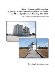
CAPE CANAVERAL AIR FORCE STATION, LAUNCH COMPLEX 39,<br />
THERMAL PROTECTION SYSTEM FACILITY<br />
(John F. Kennedy Space Center)<br />
North of the Orbiter Towway, East of Kennedy Parkway North<br />
Cape Canaveral<br />
Brevard County<br />
Florida<br />
<strong>HAER</strong> No. FL-8-11-L<br />
PHOTOGRAPHS<br />
WRITTEN HISTORICAL AND DESCRIPTIVE DATA<br />
Historic American Engineering Record<br />
National Park Service<br />
U.S. Department of the Interior<br />
100 Alabama Street, SW<br />
Atlanta, GA 30303
HISTORIC AMERICAN ENGINEERING RECORD<br />
CAPE CANAVERAL AIR FORCE STATION, LAUNCH COMPLEX 39,<br />
THERMAL PROTECTION SYSTEM FACILITY (John F. Kennedy Space Center)<br />
<strong>HAER</strong> No. FL-8-11-L<br />
Location:<br />
North of the Orbiter Towway, east of Kennedy Parkway North<br />
John F. Kennedy Space Center<br />
Cape Canaveral<br />
Brevard County<br />
Florida<br />
Date of Construction: 1986-1988<br />
U.S.G.S. 7.5. minute Orsino, Florida, quadrangle,<br />
Universal Transverse Mercator coordinates:<br />
17.533715.3162079<br />
Architect:<br />
Builder:<br />
Present Owner:<br />
Present Use:<br />
Significance:<br />
Jacobs Engineering Group, Lakeland, Florida<br />
Holloway Construction, Titusville, Florida<br />
National Aeronautics and Space Administration (NASA)<br />
Kennedy Space Center, FL 32899-0001<br />
Aerospace <strong>Facility</strong>-manufacturing spacecraft thermal protection systems<br />
The <strong>Thermal</strong> <strong>Protection</strong> <strong>System</strong> <strong>Facility</strong> (<strong>TPSF</strong>) is considered eligible for<br />
listing in the National Register of Historic Places (NRHP) in the context of<br />
the U.S. Space Shuttle program (1969-2010) under Criterion A in the area<br />
of Space Exploration. Because it has achieved significance within the past<br />
50 years, Criteria Consideration G applies. The <strong>TPSF</strong> is significant as one<br />
of only two NASA-owned assets constructed exclusively to house the<br />
manufacture and repair of the space shuttle’s thermal protection and<br />
thermal control systems, essential to the success of the Space Shuttle<br />
program. Additionally, the <strong>TPSF</strong> is considered a contributing resource to<br />
the NRHP-eligible Orbiter Processing Historic District.<br />
Project Information: The documentation of the Cape Canaveral Air Force Station, Launch<br />
Complex 39, <strong>Thermal</strong> <strong>Protection</strong> <strong>System</strong> <strong>Facility</strong> was conducted in 2010<br />
for the John F. Kennedy Space Center (KSC) by Archaeological<br />
Consultants, Inc. (ACI), under contract to Innovative Health Applications<br />
(IHA), and in accordance with KSC’s Programmatic Agreement (PA)<br />
Regarding Management of Historic Properties, dated May 18, 2009. The
CAPE CANAVERAL AIR FORCE STATION, LAUNCH COMPLEX 39,<br />
THERMAL PROTECTION SYSTEM FACILITY<br />
(John F. Kennedy Space Center)<br />
<strong>HAER</strong> No. FL-8-11-L<br />
Page 2<br />
field team consisted of architectural historian, Patricia Slovinac (ACI), and<br />
photographer, Penny Rogo Bailes. Assistance in the field was provided by<br />
Shannah Trout, IHA’s Cultural Resource Specialist. The written narrative<br />
was prepared by Ms. Slovinac; it was edited by Joan Deming, ACI Project<br />
Manager; Elaine Liston, KSC Archivist; Barbara Naylor, KSC Historic<br />
Preservation Officer; and Ms. Trout. The photographs and negatives were<br />
processed by Bob Baggett Photography, Inc.<br />
The Scope of Services for the project, which was compiled based on the<br />
PA, specifies a documentation effort following <strong>HAER</strong> Level II Standards.<br />
Information for the written narrative was primarily gathered through<br />
informal interviews with current NASA and contractor personnel and<br />
research materials housed at the KSC Archives Department. Selected<br />
drawings were provided by KSC’s Engineering Documentation Center,<br />
which serves as the repository for all facility drawings. The available<br />
drawings for the <strong>TPSF</strong> included the “as-built” drawings, as well as those<br />
depicting major modification to the facility, or any small modifications<br />
that required a set of drawings (such as changes to the electrical or<br />
mechanical systems). KSC does not periodically produce drawings of their<br />
facilities to show current existing conditions.<br />
Report Prepared<br />
by:<br />
Patricia Slovinac, Architectural Historian<br />
Archaeological Consultants, Inc.<br />
8110 Blaikie Court, Suite A<br />
Sarasota, Florida 34240<br />
Date: April 2011
CAPE CANAVERAL AIR FORCE STATION, LAUNCH COMPLEX 39,<br />
THERMAL PROTECTION SYSTEM FACILITY<br />
(John F. Kennedy Space Center)<br />
<strong>HAER</strong> No. FL-8-11-L<br />
Page 3<br />
LIST OF ACRONYMS<br />
CCAFS<br />
ET<br />
F<br />
FIB<br />
FRCI<br />
FRSI<br />
HRSI<br />
ISS<br />
JSC<br />
KSC<br />
LC<br />
LRSI<br />
MSFC<br />
NASA<br />
NRHP<br />
OPF<br />
OV<br />
RTV<br />
SIP<br />
SRB<br />
SSME<br />
STS<br />
TCS<br />
TPS<br />
<strong>TPSF</strong><br />
TUFI<br />
U.S.<br />
VAB<br />
Cape Canaveral Air Force Station<br />
External Tank<br />
Fahrenheit<br />
Flexible Insulation Blanket<br />
Fibrous Refractory Composite Insulation<br />
Felt Reusable Surface Insulation<br />
High-Temperature Reusable Surface Insulation<br />
International Space Station<br />
Johnson Space Center<br />
Kennedy Space Center<br />
Launch Complex<br />
Low-Temperature Reusable Surface Insulation<br />
Marshall Space Flight Center<br />
National Aeronautics and Space Administration<br />
National Register of Historic Places<br />
Orbiter Processing <strong>Facility</strong><br />
Orbiter Vehicle<br />
Room-Temperature Vulcanizing (silicon adhesive)<br />
Strain Isolator Pad<br />
Solid Rocket Booster<br />
Space Shuttle Main Engine<br />
Space Transportation <strong>System</strong><br />
<strong>Thermal</strong> Control <strong>System</strong><br />
<strong>Thermal</strong> <strong>Protection</strong> <strong>System</strong><br />
<strong>Thermal</strong> <strong>Protection</strong> <strong>System</strong> <strong>Facility</strong><br />
Toughened Uni-piece Fibrous Insulation<br />
United States<br />
Vehicle Assembly Building
HISTORICAL INFORMATION<br />
NASA’s John F. Kennedy Space Center<br />
CAPE CANAVERAL AIR FORCE STATION, LAUNCH COMPLEX 39,<br />
THERMAL PROTECTION SYSTEM FACILITY<br />
(John F. Kennedy Space Center)<br />
<strong>HAER</strong> No. FL-8-11-L<br />
Page 4<br />
The John F. Kennedy Space Center (KSC) is the National Aeronautics and Space<br />
Administration’s (NASA) primary Center for launch and landing operations, vehicle processing<br />
and assembly, and related programs in support of manned space missions. It is located on the<br />
east coast of Florida, about 150 miles south of Jacksonville, and to the north and west of Cape<br />
Canaveral, in Brevard and Volusia Counties, and encompasses almost 140,000 acres. The<br />
Atlantic Ocean and Cape Canaveral Air Force Station (CCAFS) are located to the east, and the<br />
Indian River is to the west.<br />
Following the launch of Sputnik I and Sputnik II, which placed Soviet satellites into Earth’s orbit<br />
in 1957, the attention of the American public turned to space exploration. President Dwight D.<br />
Eisenhower initially assigned responsibility for the U.S. Space Program to the Department of<br />
Defense. The Development Operations Division of the Army Ballistic Missile Agency, led by<br />
Dr. Wernher von Braun, began to focus on the use of missiles to propel payloads, or even a man,<br />
into space. The United States successfully entered the space race with the launch of the Army’s<br />
scientific satellite Explorer I on January 31, 1958 using a modified Jupiter missile named Juno I. 1<br />
With the realization that the military’s involvement in the space program could jeopardize the<br />
use of space for peaceful purposes, President Eisenhower established NASA on October 1, 1958<br />
as a civilian agency with the mission of carrying out scientific aeronautical and space<br />
exploration, both manned and unmanned. Initially working with NASA as part of a cooperative<br />
agreement, President Eisenhower officially transferred to NASA a large portion of the Army’s<br />
Development Operations Division, including the group of scientists led by von Braun, and the<br />
Saturn rocket program. 2<br />
NASA became a resident of Cape Canaveral in 1958 when the Army Missile Firing Laboratory,<br />
then working on the Saturn rocket project under the direction of Kurt Debus, was transferred to<br />
the agency. Several Army facilities at CCAFS were given to NASA, including various offices<br />
and hangars, as well as Launch Complexes (LC) 5, 6, 26, and 34. The Missile Firing Laboratory<br />
was renamed Launch Operations Directorate and became a branch office of Marshall Space<br />
Flight Center (MSFC). As the American space program evolved, the responsibilities of the<br />
Launch Operations Directorate grew, and NASA Headquarters separated the Directorate from<br />
1 Charles D. Benson and William B. Faherty. Gateway to the Moon. Building the Kennedy Space Center Launch<br />
Complex (Gainesville, University Press of Florida, 2001), 1-2.<br />
2 Benson and Faherty, Gateway, 15.
CAPE CANAVERAL AIR FORCE STATION, LAUNCH COMPLEX 39,<br />
THERMAL PROTECTION SYSTEM FACILITY<br />
(John F. Kennedy Space Center)<br />
<strong>HAER</strong> No. FL-8-11-L<br />
Page 5<br />
MSFC, officially designating it an independent field installation called the Launch Operations<br />
Center. 3<br />
In May 1961, President John F. Kennedy charged NASA and the associated industries to develop<br />
a space program that would surpass the Soviet program by landing a man on the Moon by the<br />
end of the decade. With the new, more powerful Saturn V rocket and the accelerated launch<br />
schedule, it was apparent that a new launch complex was required, and CCAFS, with twenty-two<br />
launch complexes, did not have the space for new rocket facilities. Merritt Island, an<br />
undeveloped area west and north of the Cape, was selected for acquisition, and in 1961 the<br />
Merritt Island Launch Area (which, with the Launch Operations Center, would become KSC)<br />
was born. In that year, NASA requested from Congress authority to purchase 80,000 acres of<br />
property, which was formally granted in 1962. The U.S. Army Corps of Engineers acted as agent<br />
for purchasing the land, which took place between 1962 and 1964. NASA began gaining title to<br />
the land in late 1962, taking over 83,903.9 acres by outright purchase, which included several<br />
small towns, such as Orsino, Wilson, Heath and Audubon, many farms, citrus groves, and<br />
several fish camps. Negotiations with the State of Florida provided submerged lands, resulting in<br />
the acquisition of property identified on the original Deed of Dedication. Much of the Stateprovided<br />
land was located south of the Old Haulover Canal and north of the Barge Canal.<br />
The American program to put a man in space and land on the Moon proceeded rapidly with<br />
widespread support. In November 1963, the Launch Operations Center and Merritt Island<br />
Launch Area were renamed John F. Kennedy Space Center to honor the late President. 4 The<br />
space program was organized into three phases: Projects Mercury, Gemini, and Apollo. Project<br />
Mercury, initiated in 1958, was executed in less than five years. Begun in 1964, Project Gemini<br />
was the intermediate step toward achieving a manned lunar landing, bridging the gap between<br />
the short-duration Mercury flights and the long-duration missions proposed for the Apollo<br />
Program. 5<br />
Apollo, the largest and most ambitious of the manned space programs, had as its goal the landing<br />
of astronauts on the Moon and their safe return to Earth. Providing the muscle to launch the<br />
spacecraft was the Saturn family of heavy vehicles. Saturn IB rockets were used to launch the<br />
early unmanned Apollo test flights and the first manned flight, Apollo 7, which carried<br />
astronauts on a ten-day earth orbital mission. 6<br />
3 Benson and Faherty, Gateway, 136.<br />
4 Harry A Butowsky. Reconnaissance Survey: Man in Space (Washington, D.C.: National Park Service, 1981), 5;<br />
Benson and Faherty, Gateway, 146.<br />
5 Butowsky, 5.<br />
6 Butowsky, 5.
CAPE CANAVERAL AIR FORCE STATION, LAUNCH COMPLEX 39,<br />
THERMAL PROTECTION SYSTEM FACILITY<br />
(John F. Kennedy Space Center)<br />
<strong>HAER</strong> No. FL-8-11-L<br />
Page 6<br />
Three different launch vehicles were used for Apollo: Saturn I, Saturn IB and Saturn V; and<br />
three different launch complexes were involved: LC 34 and LC 37 on CCAFS, and LC 39 on<br />
KSC (only LC 39 is still active). Altogether, thirty-two Saturn flights occurred (seven from LC<br />
34, eight from LC 37, and seventeen from LC 39, including Skylab and the Apollo-Soyuz Test<br />
Project) during the Apollo era. Of the total thirty-two, fifteen were manned, and of the seven<br />
attempted lunar landing missions, six were successful. No major launch vehicle failures of either<br />
Saturn IB or Saturn V occurred. There were two major command/service module failures, one on<br />
the ground (Apollo 1) and one on the way to the Moon (Apollo 13). 7<br />
The unmanned Apollo 4 mission, which lifted off on November 9, 1967, was the first Saturn V<br />
launch and the first launch from LC 39 at KSC. On July 20, 1969, the goal of landing a man on<br />
the Moon was achieved when Apollo 11 astronauts Armstrong, Aldrin, and Collins successfully<br />
executed history’s first lunar landing. Armstrong and Aldrin walked on the surface of the Moon<br />
for two hours and thirty-one minutes, and collected 21 kilograms of lunar material. Apollo 17<br />
served as the first night launch in December 1972. An estimated 500,000 people viewed the<br />
liftoff, which was the final launch of the Apollo Program. 8<br />
Skylab, an application of the Apollo Program, served as an early type of space station. With<br />
12,700 cubic feet of work and living space, it was the largest habitable structure ever placed in<br />
orbit, at the time. The station achieved several objectives: scientific investigations in Earth orbit<br />
(astronomical, space physics, and biological experiments); applications in Earth orbit (earth<br />
resources surveys); and long-duration spaceflight. Skylab 1 orbital workshop was inhabited in<br />
succession by three crews launched in modified Apollo command/service modules (Skylab 2, 3<br />
and 4). Actively used until February 1974, Skylab 1 remained in orbit until July 11, 1979, when<br />
it re-entered Earth’s atmosphere over the Indian Ocean and Western Australia after completing<br />
34,181 orbits. 9<br />
The Apollo-Soyuz Test Project of July 1975, the final application of the Apollo Program, marked<br />
the first international rendezvous and docking in space, and was the first major cooperation<br />
between the only two nations engaged in manned space flight. As the first meeting of two<br />
manned spacecraft of different nations in space, first docking, and first visits by astronauts and<br />
cosmonauts into the others’ spacecraft, the event was highly significant. The Apollo-Soyuz Test<br />
Project established workable joint docking mechanisms, taking the first steps toward mutual<br />
rescue capability of both Russian and American manned missions in space. 10<br />
7 NASA. Facts: John F. Kennedy Space Center (1994), 82.<br />
8 NASA. Facts, 86-90.<br />
9 NASA. Facts, 91.<br />
10 NASA. Facts, 96.
CAPE CANAVERAL AIR FORCE STATION, LAUNCH COMPLEX 39,<br />
THERMAL PROTECTION SYSTEM FACILITY<br />
(John F. Kennedy Space Center)<br />
<strong>HAER</strong> No. FL-8-11-L<br />
Page 7<br />
On January 5, 1972, President Nixon delivered a speech in which he outlined the end of the<br />
Apollo era and the future of a reusable space flight vehicle, the Space Shuttle, which would<br />
provide “routine access to space.” By commencing work at this time, Nixon added, “we can have<br />
the Shuttle in manned flight by 1978, and operational a short time after that.” 11 The Space Task<br />
Group, previously established by President Nixon in February 1969 to recommend a future<br />
course for the U.S. Space Program, presented three choices of long-range space plans. All<br />
included an Earth–orbiting space station, a space shuttle, and a manned Mars expedition. 12<br />
Although none of the original programs presented was eventually selected, NASA implemented<br />
a program, shaped by the politics and economic realities of its time that served as a first step<br />
toward any future plans for implementing a space station. 13<br />
During this speech, President Nixon instructed NASA to proceed with the design and building of<br />
a partially reusable space shuttle consisting of a reusable orbiter, three reusable main engines,<br />
two reusable solid rocket boosters (SRBs), and one non-reusable external liquid fuel tank (ET).<br />
NASA’s administrators vowed that the shuttle would fly at least fifty times a year, making space<br />
travel economical and safe. NASA gave responsibility for developing the shuttle orbiter vehicle<br />
and overall management of the Space Shuttle program to the Manned Spacecraft Center (now<br />
known as the Johnson Space Center [JSC]) in Houston, Texas, based on the Center’s experience.<br />
MSFC in Huntsville, Alabama was responsible for development of the Space Shuttle Main<br />
Engine (SSME), the SRBs, the ET, and for all propulsion-related tasks. Engineering design<br />
support continued at JSC, MSFC and NASA’s Langley Research Center, in Hampton, Virginia,<br />
and engine tests were to be performed at NASA’s National Space Technology Laboratories (later<br />
named Stennis Space Center) in south Mississippi, and at the Air Force’s Rocket Propulsion<br />
Laboratory in California, which later became the Santa Susana Field Laboratory. 14 NASA<br />
selected KSC as the primary launch and landing site for the Space Shuttle program. KSC,<br />
responsible for designing the launch and recovery facilities, was to develop methods for shuttle<br />
assembly, checkout, and launch operations. 15<br />
On September 17, 1976, the full-scale Orbiter Vehicle (OV) prototype Enterprise (OV- 101) was<br />
completed. Designed for test purposes only and never intended for space flight, structural<br />
11 Marcus Lindroos. “President Nixon’s 1972 Announcement on the Space Shuttle.” (NASA Office of Policy and<br />
Plans, NASA History Office, updated 14 April 2000).<br />
12 NASA, History Office, NASA Headquarters. “Report of the Space Task Group, 1969.”<br />
13 Dennis R. Jenkins. Space Shuttle, The History of the National Space Transportation <strong>System</strong>. The First 100<br />
Missions (Cape Canaveral, Florida: Specialty Press, 2001), 99.<br />
14 Jenkins, 122.<br />
15 Linda Neuman Ezell. NASA Historical Databook Volume III Programs and Projects 1969-1978. The NASA<br />
History Series, NASA SP-4012 (Washington, D.C.: NASA History Office, 1988), Table 2-57; Ray A. Williamson.<br />
“Developing the Space Shuttle.” Exploring the Unknown: Selected Documents in the History of the U.S. Civil Space<br />
Program, Volume IV: Accessing Space (Edited by John M. Logsdon. Washington, D.C.: U.S. Printing Office, 1999),<br />
172-174.
CAPE CANAVERAL AIR FORCE STATION, LAUNCH COMPLEX 39,<br />
THERMAL PROTECTION SYSTEM FACILITY<br />
(John F. Kennedy Space Center)<br />
<strong>HAER</strong> No. FL-8-11-L<br />
Page 8<br />
assembly of this orbiter had started more than two years earlier in June 1974 at Air Force Plant<br />
42 in Palmdale, California. Although the Enterprise was an aluminum shell prototype incapable<br />
of space flight, it reflected the overall design of the orbiter. As such, it served successfully in<br />
1977 as the test article during the Approach and Landing Tests aimed at checking out both the<br />
mating with the Boeing 747 Shuttle Carrier Aircraft (SCA) for ferry operations, as well as the<br />
orbiter’s unpowered landing capabilities.<br />
The first orbiter intended for spaceflight, Columbia (OV-102), arrived at KSC from Air Force<br />
Plant 42 in March 1979. Originally scheduled for liftoff in late 1979, the launch date was delayed<br />
by problems with both the SSME components as well as the thermal protection system (TPS).<br />
Columbia spent 610 days in the Orbiter Processing <strong>Facility</strong> (OPF), another thirty-five days in the<br />
Vehicle Assembly Building (VAB) and 105 days on Launch Pad 39A before finally lifting off on<br />
April 12, 1981. Flight No. STS-1, the first orbital test flight and first Space Shuttle program<br />
mission, ended with a landing on April 14 at Edwards Air Force Base (EAFB) in California. This<br />
launch demonstrated Columbia’s ability to fly into orbit, conduct on-orbit operations, and return<br />
safely. 16 Columbia flew three additional test flights in 1981 and 1982, all with a crew of two. The<br />
Orbital Test Flight Program ended in July 1982 with 95 percent of its objectives accomplished.<br />
After the end of the fourth mission, President Reagan declared that with the next flight the<br />
Shuttle would be “fully operational.”<br />
By the end of the Space Shuttle program, a total of 135 missions will have been launched from<br />
KSC. From April 1981 until the Challenger accident in January 1986, between two and nine<br />
missions were flown yearly, with an average of four to five per year. The milestone year was<br />
1985, when nine flights were successfully completed. The years between 1992 and 1997 were<br />
the most productive, with seven or eight yearly missions. Since 1995, in addition to its unique<br />
responsibility as the shuttle launch site, KSC also became the preferred landing site.<br />
Over the past two decades, the Space Shuttle program has launched a number of planetary and<br />
astronomy missions including the Hubble Space Telescope, the Galileo probe to Jupiter,<br />
Magellan to Venus, and the Upper Atmospheric Research Satellite. In addition to astronomy and<br />
military satellites, a series of Spacelab research missions were flown, which carried dozens of<br />
international experiments in disciplines ranging from materials science to plant biology.<br />
Spacelab was a manned, reusable, microgravity laboratory flown into space in the rear of the<br />
space shuttle cargo bay. It was developed on a modular basis allowing assembly in a dozen<br />
arrangements depending on the specific mission requirements. 17 The first Spacelab mission,<br />
carried aboard Columbia (Flight No. STS-9), began on November 28, 1983. Four Spacelab<br />
missions were flown between 1983 and 1985. Following a stand-down in the aftermath of the<br />
Challenger disaster, the next Spacelab mission was not launched until 1990. In total, twenty-four<br />
16 Jenkins, 268.<br />
17 NASA. NASA Shuttle Reference Manual (1988).
CAPE CANAVERAL AIR FORCE STATION, LAUNCH COMPLEX 39,<br />
THERMAL PROTECTION SYSTEM FACILITY<br />
(John F. Kennedy Space Center)<br />
<strong>HAER</strong> No. FL-8-11-L<br />
Page 9<br />
space shuttle missions carried Spacelab hardware before the program was decommissioned in<br />
1998. 18 In addition to astronomical, atmospheric, microgravity, and life sciences missions,<br />
Spacelab was also used as a supply carrier to the Hubble Space Telescope and the Soviet space<br />
station Mir.<br />
In 1995, a joint U.S./Russian Shuttle-Mir Program was initiated as a precursor to construction of<br />
the International Space Station (ISS). Mir was launched in February 1986 and remained in orbit<br />
until March 2001. 19 The first approach and flyaround of Mir took place on February 3, 1995<br />
(STS-63); the first Mir docking was in June 1995 (STS-71). During the three-year Shuttle-Mir<br />
Program (June 27, 1995 to June 2, 1998) the space shuttle docked with Mir nine times. All but<br />
the last two of these docking missions used the Orbiter Atlantis. In 1995, Dr. Norman Thagard<br />
was the first American to live aboard the Russian space station. Over the next three years, six<br />
more U.S. astronauts served tours on Mir. The shuttle served as a means of transporting supplies,<br />
equipment and water to the space station in addition to performing a variety of other mission<br />
tasks, many of which involved earth science experiments. It returned to Earth experiment results<br />
and unneeded equipment. The Shuttle-Mir program served to acclimate the astronauts to living<br />
and working in space. Many of the activities carried out were types they would perform on the<br />
ISS. 20<br />
On December 4, 1999, Endeavour (STS-88) launched the first component of the ISS into orbit.<br />
This event marked, “at long last the start of the Shuttle’s use for which it was primarily designed<br />
– transport to and from a permanently inhabited orbital space station.” 21 STS-96, launched on<br />
May 27, 1999, marked the first mission to dock with the ISS. Since that time, most space shuttle<br />
missions have supported the continued assembly of the space station. As currently planned, ISS<br />
assembly missions will continue through the life of the Space Shuttle program.<br />
The Space Shuttle program suffered two major setbacks with the tragic losses of the Challenger<br />
and Columbia on January 28, 1986 and February 1, 2003, respectively. Following the Challenger<br />
accident, the program was suspended, and President Ronald Reagan formed a thirteen-member<br />
commission to identify the cause of the disaster. The Rogers Commission report, issued on June<br />
6, 1986, which also included a review of the Space Shuttle program, concluded “that the drive to<br />
declare the Shuttle operational had put enormous pressures on the system and stretched its<br />
resources to the limit”. 22 In addition to mechanical failure, the Commission noted a number of<br />
18 STS-90, which landed on 3 May 1998, was the final Spacelab mission. NASA KSC. “Shuttle Payloads and<br />
Related Information.” KSC Factoids. Revised 18 November 2002.<br />
19 Tony Reichhardt (editor). Space Shuttle, The First 20 Year. (Washington, D.C.: Smithsonian Institution, 2002),<br />
85.<br />
20 Judy A. Rumerman, with Stephen J. Garber. Chronology of Space Shuttle Flights 1981-2000. HHR-70<br />
(Washington, D.C.: NASA History Division, Office of Policy and Plans, October 2000), 3.<br />
21 Williamson, 191.<br />
22 Columbia Accident Investigation Board. Report Volume I (August 2003), 25.
CAPE CANAVERAL AIR FORCE STATION, LAUNCH COMPLEX 39,<br />
THERMAL PROTECTION SYSTEM FACILITY<br />
(John F. Kennedy Space Center)<br />
<strong>HAER</strong> No. FL-8-11-L<br />
Page 10<br />
NASA management failures that contributed to the catastrophe. As a result, among the tangible<br />
actions taken were extensive redesign of the SRBs; upgrading of the space shuttle tires, brakes,<br />
and nose wheel steering mechanisms; the addition of a drag chute to help reduce speed upon<br />
landing; the addition of a crew escape system; and the requirement for astronauts to wear<br />
pressurized flight safety suits during launch and landing operations. Other changes involved<br />
reorganization and decentralization of the Space Shuttle program. NASA moved the<br />
management of the program from JSC to NASA Headquarters, with the aim of preventing<br />
communication deficiencies. 23 Experienced astronauts were placed in key NASA management<br />
positions, all documented waivers to existing flight safety criteria were revoked and forbidden,<br />
and a policy of open reviews was implemented. 24 In addition, NASA adopted a space shuttle<br />
flight schedule with a reduced average number of launches, and discontinued the long-term<br />
practice of launching commercial and military payloads. 25 The launch of Discovery (STS-26)<br />
from KSC Pad 39B on September 29, 1988 marked a Return to Flight after a thirty-two-month<br />
stand-down in manned spaceflight following the Challenger accident.<br />
In the aftermath of the 2003 Columbia accident, a seven month investigation ensued, concluding<br />
with the findings of the Columbia Accident Investigation Board, which determined that both<br />
technical and management conditions accounted for the loss of the orbiter and crew. According<br />
to the Board’s Report, the physical cause of the accident was a breach in the TPS on the leading<br />
edge of the left wing, caused by a piece of insulating foam, which separated from the ET after<br />
launch and struck the wing. 26 NASA spent more than two years researching and implementing<br />
safety improvements for the orbiters, SRBs and ET. Following a two-year stand-down, the<br />
launch of STS-114 on July 26, 2005 marked the first Return to Flight since the loss of Columbia.<br />
On January 14, 2004, President George W. Bush outlined a new space exploration initiative in a<br />
speech given at NASA Headquarters.<br />
Today I announce a new plan to explore space and extend a human presence<br />
across our solar system . . . Our first goal is to complete the International Space<br />
Station by 2010 . . . The Shuttle’s chief purpose over the next several years will be<br />
to help finish assembly of the International Space Station. In 2010, the Space<br />
Shuttle – after nearly 30 years of duty – will be retired from service. . . 27<br />
23 CAIB, 101.<br />
24 Cliff Lethbridge. “History of the Space Shuttle program.” (2001), 4.<br />
25 Lethbridge, 5.<br />
26 CAIB, 9.<br />
27 The White House. “A Renewed Spirit of Discovery – The President’s Vision for Space Exploration.” (January<br />
2004).
CAPE CANAVERAL AIR FORCE STATION, LAUNCH COMPLEX 39,<br />
THERMAL PROTECTION SYSTEM FACILITY<br />
(John F. Kennedy Space Center)<br />
<strong>HAER</strong> No. FL-8-11-L<br />
Page 11<br />
Following the President’s speech, NASA released The Vision for Space Exploration, which<br />
outlined the Agency’s approach to the new direction in space exploration. 28 As part of this<br />
initiative, NASA will continue to use the space shuttle to complete assembly of the ISS. The<br />
Shuttle will not be upgraded to serve beyond 2010 and, after completing the ISS, the Space<br />
Shuttle program will be retired.<br />
28 NASA Headquarters. “The Vision for Space Exploration.” (February 2004).
Development of KSC’s LC 39 and VAB Areas<br />
CAPE CANAVERAL AIR FORCE STATION, LAUNCH COMPLEX 39,<br />
THERMAL PROTECTION SYSTEM FACILITY<br />
(John F. Kennedy Space Center)<br />
<strong>HAER</strong> No. FL-8-11-L<br />
Page 12<br />
Today, KSC maintains operational control over 3,800 acres, all located in Brevard County. The<br />
major facilities are located within the Industrial Area, the LC 39 Area, the VAB Area, and the<br />
Shuttle Landing <strong>Facility</strong> Area. The LC 39 and VAB Areas were developed primarily to support<br />
launch vehicle operations and related launch processing activities. They contain the VAB, the<br />
Launch Control Center, the OPFs, the two Launch Pads, A and B, and other support facilities.<br />
Following completion of the Apollo-Soyuz Test Project in 1975, the facilities at KSC were<br />
modified to support the Space Shuttle program. KSC was originally one of three possible launch<br />
sites evaluated, along with Vandenberg Air Force Base in California and the White Sands<br />
Missile Range in New Mexico. Compared with the other two locations, KSC had the advantage<br />
of approximately $1 billion in existing launch facilities. Thus, less time and money would be<br />
needed to modify existing facilities at KSC rather than to build new ones at another location. The<br />
estimate of $200 to $400 million to modify the existing KSC facilities was roughly half the cost<br />
of new construction. In addition, only KSC had abort options for a first revolution return of the<br />
low cross-range orbiter. 29<br />
To help keep costs down, beginning ca. 1976, KSC engineers adapted and modified many of the<br />
Apollo launch facilities to serve the needs of the Space Shuttle program. Among the key<br />
facilities undergoing change were the VAB, the Launch Control Center, and LC 39 Pads A and<br />
B. New facilities were constructed only when a unique requirement existed. The major new<br />
structures included the Shuttle Landing <strong>Facility</strong> and the OPFs. Multi-million dollar contracts for<br />
design and construction were awarded to both national and local firms, including Reynolds,<br />
Smith and Hills of Jacksonville, Florida; the Frank Briscoe Company, Inc. of East Orange, New<br />
Jersey; Algernon Blair Industrial Contractors, Inc. of Norcross, Georgia; the Holloway<br />
Corporation of Titusville, Florida; and W&J Construction Corporation of Cocoa, Florida.<br />
Alterations to the VAB included modification of two of the four high bays for assembly of the<br />
space shuttle vehicle, and changes to the other two high bays to accommodate the processing and<br />
stacking of the SRBs and ET. The north doors were widened by almost 40’ to permit entry of the<br />
towed orbiter. Work platforms shaped to fit the shuttle configuration were added to High Bays 1<br />
and 3 where shuttle assembly takes place, and internal structural changes were also made to High<br />
Bays 2 and 4, where the ETs are processed.<br />
Major changes were made to LC 39, Pads A and B. Modifications were completed in mid-1978<br />
at Pad A and in 1985 at Pad B. With the exception of the six fixed pedestals which support the<br />
Mobile Launcher Platform, all of the structures on the hardstands of each pad were removed or<br />
relocated. Fuel, oxidizer, high-pressure gas, electrical, and other service lines were rerouted.<br />
29 Jenkins, 112.
CAPE CANAVERAL AIR FORCE STATION, LAUNCH COMPLEX 39,<br />
THERMAL PROTECTION SYSTEM FACILITY<br />
(John F. Kennedy Space Center)<br />
<strong>HAER</strong> No. FL-8-11-L<br />
Page 13<br />
New hypergolic fuel and oxidizer support areas were constructed at the southwest and southeast<br />
corners, respectively, of the pads; the Saturn fuel support area was removed, a new Fixed Service<br />
Structure was erected using an original Apollo-era Launch Umbilical Tower, a Rotating Service<br />
Structure was added, the Saturn flame deflectors were replaced, and a Payload Changeout Room<br />
and a Payload Ground Handling Mechanism were added. A sound suppression water system was<br />
installed on the pads to reduce the acoustical levels within the orbiter’s payload and thus, to<br />
protect it and its payloads from damage. A related system, the Overpressure Suppression <strong>System</strong>,<br />
was installed to reduce the pressure pulse at SRB ignition. 30<br />
Additional changes were made to Pad A and Pad B in the aftermath of the 1986 Challenger<br />
accident; other modifications followed the Return to Flight in 1988. Among the modifications<br />
were the installation of new weather protection structures to supplement the Rotating Service<br />
Structure; improvements in temperature and humidity controls for the Payload Changeout Room;<br />
upgrades to the emergency exit system, including the addition of two slidewire baskets;<br />
installation of new elevators on the Rotating Service Structure; and improvements to the pad<br />
communications system. Changes were first made at Pad B, followed by identical changes at Pad<br />
A.<br />
The <strong>Thermal</strong> <strong>Protection</strong> <strong>System</strong> <strong>Facility</strong><br />
The <strong>Thermal</strong> <strong>Protection</strong> <strong>System</strong> <strong>Facility</strong> (<strong>TPSF</strong>) is considered to be individually eligible for<br />
listing in the NRHP under Criterion A in the area of Space Exploration, as a contributing<br />
resource to the Historic Cultural Resources of the John F. Kennedy Space Center multiple<br />
property submission in the context of the U.S. Space Shuttle Program (ca. 1969-2011). Because<br />
it has achieved significance within the past 50 years, Criteria Consideration G applies. In<br />
addition to its individual eligibility, the <strong>TPSF</strong> is considered a contributing resource to the Orbiter<br />
Processing Historic District. The period of significance for the <strong>TPSF</strong> is from 1988, the date of its<br />
completed construction, through 2011, the designated end of the Space Shuttle Program. The<br />
<strong>TPSF</strong> is significant as one of only two NASA-owned assets constructed for the exclusive<br />
purpose of manufacturing and repairing elements of the Space Shuttle’s thermal protection and<br />
thermal control systems, which include tiles, gap fillers, and insulation blankets, as well as<br />
coatings and adhesives.<br />
A major emphasis of the Space Shuttle program was cost effectiveness through the reusability of<br />
vehicle elements. The TPS protected the orbiter vehicle upon reentry into the Earth’s<br />
atmosphere, when its surface temperatures could reach as high as 3,000 degrees Fahrenheit, as<br />
well as the extremely cold conditions experienced during the night phase of each orbit. 31 As with<br />
30 Wallace H. Boggs and Samuel T. Beddingfield. “Moonport to Spaceport. The Changing Face at KSC.”<br />
Astronautics & Aeronautics, July-August 1982, 28-41.<br />
31 NASA. NASA Facts: Orbiter <strong>Thermal</strong> <strong>Protection</strong> <strong>System</strong>. FS-2004-09-014-KSC. September 2004.
CAPE CANAVERAL AIR FORCE STATION, LAUNCH COMPLEX 39,<br />
THERMAL PROTECTION SYSTEM FACILITY<br />
(John F. Kennedy Space Center)<br />
<strong>HAER</strong> No. FL-8-11-L<br />
Page 14<br />
any repeatedly used item, the different TPS components were subject to “wear and tear,”<br />
especially due to the harsh conditions to which the vehicle was subjected, as well as impact<br />
damage from debris and other materials. The <strong>TPSF</strong> provided a facility at KSC where a TPS<br />
component could be repaired, or if necessary, its replacement could be manufactured.<br />
The <strong>Thermal</strong> <strong>Protection</strong> <strong>System</strong> for the Space Shuttle Orbiters<br />
A spacecraft’s reentry in the Earth’s atmosphere creates very large heat loads and aerodynamic<br />
forces that could compromise the structural integrity of a spacecraft (as with the Columbia<br />
accident in February 2003). NASA’s first space programs, Mercury, Gemini, and Apollo, used<br />
ablative heat shields, which by their nature, were not reusable. By 1970, with development of the<br />
space shuttle underway, NASA sought a type of heat shield that would be reusable. One of the<br />
alternate reusable heat shields under consideration was known as reusable surface insulation<br />
(RSI), which led directly to the development of thermal ceramic tiles.<br />
Lockheed-Martin’s research center in Palo Alto, California, had undertaken research and<br />
development for this type of thermal protection shield, beginning in the early 1960s. By 1970-<br />
1971, they had a functioning plant to manufacture silica-based RSI tiles. Experimentation for<br />
improved tile materials continued, and in late 1972 NASA ran a series of tests at several of its<br />
centers. At JSC, Lockheed’s tiles were the only ones that survived the final series of thermalacoustic<br />
tests. 32 Thus, Rockwell International, the prime orbiter contractor, awarded Lockheed<br />
the subcontract for producing most of the shuttle’s TPS. Manufacturing of the tiles for the space<br />
shuttle began at Lockheed’s Sunnyvale, California, plant in 1976, with the first shipment in early<br />
1977. In the mid-1980s, Rockwell took over the manufacture of TPS materials in Palmdale,<br />
California.<br />
Since the orbiter’s Approach and Landing Test program occurred entirely within the Earth’s<br />
atmosphere, Rockwell used Styrofoam tiles on the Enterprise, as was acceptable for the<br />
spacecraft’s role as a test vehicle. Therefore, Columbia was the first shuttle to be fitted with the<br />
new thermal tiles. Since the tiles were extremely fragile, each was fitted with a Strain Isolator<br />
Pad (SIP), which would be placed against the skin of the shuttle. During tile installation, NASA<br />
encountered major challenges in the tile adhesive process, with many tiles not passing the<br />
required “pull test,” meant to ensure that they would not fall off the vehicle during launch. A<br />
TPS team was created, with the single purpose of solving the tile-bonding problem. Their<br />
solution was the development of a slurry coating, which was applied to the underside of the tile;<br />
the process became known as “tile densification.” 33<br />
32 Jenkins, 237-238; Joan Lisa Bromberg. NASA and the Space Industry (Baltimore: Johns Hopkins University<br />
Press, 1999, 100.<br />
33 George Diller. “Reyes’ team met tile challenges.” Spaceport News (40, 8), April 12, 2001: 3.
CAPE CANAVERAL AIR FORCE STATION, LAUNCH COMPLEX 39,<br />
THERMAL PROTECTION SYSTEM FACILITY<br />
(John F. Kennedy Space Center)<br />
<strong>HAER</strong> No. FL-8-11-L<br />
Page 15<br />
As initially designed, Columbia’s TPS was comprised of over 33,000 tiles that covered most of<br />
the structure, with some Felt Reusable Surface Insulation (FRSI) blankets over portions of the<br />
upper wing surfaces and mid-fuselage. NASA testing and evaluation of the tiles, as well as other<br />
forms of thermal protection, continued through the 1970s, especially at the Ames Research<br />
Center in California. Following the initial delivery of Columbia and the assembly of Challenger,<br />
a newer blanket called Advanced FRSI, or Fibrous Insulation Blanket (FIB), was used<br />
generously as a replacement for LRSI tiles on Discovery and Atlantis. By the time Endeavour<br />
was assembled, its TPS contained roughly 26,000 tiles.<br />
Presently, the space shuttle orbiter’s TPS system is comprised of three base components:<br />
Reinforced Carbon-Carbon panels, insulation tiles, and “softgoods.” Reinforced Carbon-Carbon<br />
is used to protect areas subjected to extreme temperatures (more than 2300 degrees Fahrenheit<br />
[F]), as well as high aerodynamic forces during launch and reentry. Such areas include the nose<br />
cap, the wing leading edges, and the area around the forward orbiter/ET structural attachment.<br />
The insulation tiles on the orbiter take four different forms, High-Temperature Reusable Surface<br />
Insulation (HRSI) tiles, Low-Temperature Reusable Surface Insulation (LRSI) tiles, Fibrous<br />
Refractory Composite Insulation (FRCI) tiles, and Toughened Uni-piece Fibrous Insulation<br />
(TUFI) tiles. HRSI tiles, which protect against temperatures less than 2300 degrees F, are<br />
typically used on the underside of the orbiter and portions of the forward fuselage, vertical<br />
stabilizer, orbital maneuvering system pods, body flap, and elevons. Some areas of the orbiter<br />
that were originally fitted with HRSI tile, are now shielded with FRCI tile, which is about 10<br />
percent lighter in weight; TUFI tiles have replaced HRSI tiles on areas such as the body flap and<br />
base heat shield. 34 All three of these tile types are painted black for maximum heat loss during<br />
reentry. LRSI tiles are used on select areas of the forward, mid-, and aft fuselages, as well as<br />
portions of the orbital maneuvering system pods, vertical tail, and upper wing surfaces, all of<br />
which are areas where temperatures are less than 1200 degrees F. These tiles are painted white to<br />
provide thermal control for the vehicle while it is in orbit.<br />
All of the tile materials arrive at KSC in the form of a large block, known as a production unit.<br />
HRSI and LRSI tiles are made from a slurry of silica glass fibers and water, and have a density<br />
of either 9 pounds per cubic foot or 22 pounds per cubic foot; only 10 percent of the total volume<br />
is solid material. This material was developed by Lockheed Missiles and Space Company in<br />
Sunnyvale, California; the company still manufactures the production units. FRCI tiles are<br />
composed from a slurry made with silica glass fibers, Nextel, and water, and have a density of 12<br />
pounds per cubic foot. 35 TUFI tiles are made of the same base materials as the HRSI and LRSI<br />
tiles, but use a stronger surface coating that actually permeates the core of the tile. Both FRCI<br />
34 NASA, <strong>Thermal</strong> <strong>Protection</strong> <strong>System</strong>.<br />
35 Nextel is the trademark name for an alumino-boro-silicate fiber developed by the 3M Company.
CAPE CANAVERAL AIR FORCE STATION, LAUNCH COMPLEX 39,<br />
THERMAL PROTECTION SYSTEM FACILITY<br />
(John F. Kennedy Space Center)<br />
<strong>HAER</strong> No. FL-8-11-L<br />
Page 16<br />
and TUFI were developed by NASA’s Ames Research Center, and the production units are<br />
manufactured at Lockheed’s Sunnyvale plant.<br />
In the language of TPS, the term “softgoods” is used to refer to TPS insulation blankets, gap<br />
fillers, thermal barriers, and thermal control blankets. There are two different styles of TPS<br />
insulation blankets: FRSI blankets and FIBs, which are also known as Advanced FRSI blankets.<br />
FRSI blankets, like SIPs, are comprised of Nomex felt 36 that is then coated with a silicone rubber<br />
paint; they are used on the upper surfaces of both the payload bay doors and the wings. FIBs are<br />
made by placing a core of pure silica felt in between a layer of silica fabric (outer side) and a<br />
layer of glass fabric. These blankets, which range in thickness from 0.33” to 2.04”, are used on<br />
the sides and upper wing surfaces of the orbiter, as well as portions of the upper forward<br />
fuselage. They are considered a replacement for LRSI tiles. 37<br />
Due to the different thermal expansion properties of the orbiter’s airframe and TPS tiles, gaps are<br />
left in between the individual tiles to accommodate for the materials’ expansion and contraction;<br />
however, these gaps cannot be too large, or hot gases will seep through during reentry and cause<br />
severe damage. Thus, gap fillers were created to reconcile the need for gaps, while minimizing<br />
their size and also providing some padding between the tiles. Gap fillers are made of Nomex felt<br />
and are typically 0.75” wide. <strong>Thermal</strong> barriers operate in a similar fashion to gap fillers, by<br />
filling space left between TPS components and orbiter features, such as the landing gear doors or<br />
the crew hatch. They are typically made with ceramic cloth wrapped around a tubular spring. 38<br />
The fourth type of softgood is a <strong>Thermal</strong> Control <strong>System</strong> (TCS) blanket, which is applied to the<br />
inner surfaces of the payload bay to help regulate the temperatures of the orbiter’s systems and<br />
components. 39 There are two types of TCS blankets. The first is called a fibrous bulk blanket,<br />
and is made with a core of fibrous materials that has a density of 2 pounds per cubic foot, which<br />
is encased with a layer of Kapton. 40 The second type of TCS blanket is the multilayer blanket,<br />
which is formed from alternate layers of reflective Kapton film and Dacron net separators. 41<br />
Construction of the <strong>TPSF</strong><br />
In March 1979, the first orbiter destined to fly in space, Columbia, arrived at KSC, missing<br />
roughly 7,800 of its TPS tiles and nearly all of its tiles requiring the densification process. 42<br />
While the orbiter was placed in High Bay No. 1 of the OPF for processing, High Bay No. 2 of<br />
36 Nomex is the trademark name for a rigid, heat resistant felt manufactured by DuPont.<br />
37 Jenkins, 400-401; NASA, <strong>Thermal</strong> <strong>Protection</strong> <strong>System</strong>, 3-5.<br />
38 Jenkins, 402.<br />
39 Jenkins, 402; Kevin Harrington. Personal communication with Patricia Slovinac, KSC, <strong>TPSF</strong>, March 9, 2010.<br />
40 Kapton is an acrylic-like film developed by DuPont, that can handle a wide range of temperatures.<br />
41 Jenkins, 402; Dacron is the trademark name for a synthetic polyester fabric.<br />
42 Frank E. Jarrett. “Chronology of KSC and KSC Related Events for 1979.” KHR-4, September 22, 1980, 26.
CAPE CANAVERAL AIR FORCE STATION, LAUNCH COMPLEX 39,<br />
THERMAL PROTECTION SYSTEM FACILITY<br />
(John F. Kennedy Space Center)<br />
<strong>HAER</strong> No. FL-8-11-L<br />
Page 17<br />
the OPF was adapted as a support area for completing work on the tiles. In summer 1980, KSC<br />
began planning for the construction of a facility dedicated to tile production, so that High Bay<br />
No. 2 could be readied for the arrival of the next orbiter, Challenger. Construction of the base<br />
structure of the TPS facility was set to begin in December 1980, with the installation of building<br />
systems and equipment scheduled to start February 1981. 43 For unidentified reasons, these plans<br />
were delayed.<br />
By the mid-1980s, most TPS work was still being done at Rockwell International’s plant in<br />
Downey, California (roughly 2,200 miles from KSC), or temporary quarters at KSC. By<br />
establishing a formal TPS facility at KSC, NASA could “expedite routine maintenance as well as<br />
the refurbishment work required on orbiters between missions.” 44 Design work for the <strong>Thermal</strong><br />
<strong>Protection</strong> <strong>System</strong> <strong>Facility</strong> (<strong>TPSF</strong>) was completed between March and September 1985 by the<br />
architecture/engineering firm of Jacobs Engineering Group, Inc., of Lakeland, Florida. They<br />
arranged the ground floor “based on the sequence of operations required to transform tile<br />
material into finished tiles.” 45 Each phase of the fabrication process was given its own<br />
specialized work area; these areas are connected by a central corridor, to allow for the efficient<br />
movement of the materials and products from one area to another. 46<br />
The <strong>TPSF</strong> was constructed by the Holloway Corporation of Titusville, Florida, between July<br />
1986 and May 1988, for a cost of approximately $4.5 million (Figure A-1). Although the facility<br />
was officially declared open at its ribbon cutting ceremony (May 2, 1988), final checkouts and<br />
installation of equipment continued until August of that year. Tile manufacturing was first<br />
completed here in 1994; blanket manufacturing did not occur until 2004. 47 For its first sixteen<br />
years, the <strong>TPSF</strong> underwent very few alterations. This work included the construction of two<br />
small rooms within the southeast corner of Room No. 122, and two rooms at the east end of<br />
Room No. 127 (see Photo Nos. 49 and 50 for room locations).<br />
In September 2004, Hurricane Frances caused significant damage to the <strong>TPSF</strong>, as it made its way<br />
up the east coast of Florida. Roughly 35 percent of the facility’s roof was lost, which caused<br />
uninhabitable conditions on the second floor level; the first floor received only minor water<br />
damage. Rehabilitation work on the building included the reconstruction of the first floor roof<br />
and the second floor walls and roof. In addition, the interior layout of the second floor changed<br />
from the original three-room configuration (see Photo No. 50) to a two-room configuration (see<br />
Figure No. A-2). All work was completed by November 2005.<br />
43 “Two New Facilities Planned.” Spaceport News (19, 16), August 1, 1980: 1 and 4.<br />
44 Pat Phillips. “Shuttle tile work closer to home.” Spaceport News (27, 11), May 20, 1988: 7.<br />
45 Jacobs Engineering Group Inc, Lakeland. Design Data Manual Final Submittal, <strong>Thermal</strong> <strong>Protection</strong> <strong>System</strong>s<br />
<strong>Facility</strong>, Launch Complex 39. September 3, 1985, 1-1.<br />
46 Jacobs Engineering Group, Data Manual; Phillips.<br />
47 Phillips; “Inside The Tile Shop.” Spaceport News (39, 19), September 22, 2000: 5; “KSC makes Shuttle heatshield<br />
blankets.” Spaceport News (44, 1), January 7, 2005: 7.
CAPE CANAVERAL AIR FORCE STATION, LAUNCH COMPLEX 39,<br />
THERMAL PROTECTION SYSTEM FACILITY<br />
(John F. Kennedy Space Center)<br />
<strong>HAER</strong> No. FL-8-11-L<br />
Page 18<br />
<strong>TPSF</strong> Functions<br />
Presently, the space shuttle orbiter’s TPS system is comprised of three base components:<br />
Reinforced Carbon-Carbon panels, insulation tiles, and insulation blankets. The Reinforced<br />
Carbon-Carbon panels are manufactured by Lockheed-Martin’s Missile and Fire Control<br />
Facilities in Dallas, Texas. 48 The remainder of the TPS components are manufactured or repaired<br />
within the <strong>TPSF</strong>, when they are either worn out from age or damaged during a mission.<br />
Tile Production<br />
When technicians at the OPF need a new tile for the orbiter, one of two things occurs, either they<br />
create a foam version of the tile using the tile cavity as a mold, or they take a set of photographic<br />
images of the tile cavity. In either case, the model or images are sent to the Tile Machining<br />
Room (Room No. 122) in the <strong>TPSF</strong>. The foam model is considered to be in a ‘ready-to-use’<br />
state, whereas the images must be uploaded to a facility computer, which takes the information<br />
and turns it into a set of electronic specifications. The foam model or electronic specifications are<br />
then used by a mill operator to form the actual tile from a production unit, using one of the<br />
room’s milling machines.<br />
There are six milling machines in the facility: two manually operated mills, three semi-automatic<br />
mills, and one fully-automatic mill. Each of the two manually-operated machines operates in a<br />
similar fashion as a key duplication machine, and is used to make specific types of cuts. The mill<br />
operator begins by placing a production unit on the cutting table of the contour milling machine,<br />
while the foam tile is placed on an adjacent surface (Figure Nos. A-3, A-4). The operator then<br />
uses a styler to trace the foam tile, providing directions to the cutting tool, which sculpts the<br />
production unit to match the model (Figure Nos. A-5, A-6). Afterwards, if there are beveled<br />
surfaces or other non-standard cuts, the tile and foam model are moved to the detail milling<br />
machine, which has a rotating table. If electronic specifications were generated, as opposed to a<br />
foam model, either the fully-automatic or one of the semi-automatic mills is used to carve the<br />
tile. In such a case, the operator loads the specifications into the mill’s computer system, which<br />
mechanically guide the actions of the mill, making all of the cuts to form a complete tile (Figure<br />
Nos. A-7 through A-10). 49<br />
After the tile is cut, it is sent to the Heat Cleaning Ovens/Tile Firing Kilns Room (Room No.<br />
123) to be heat cleaned, a process which takes up to eight hours from initial heat-up of the oven<br />
to final cool-down of the material (Figure Nos. A-11 through A-14). The tile is then taken into<br />
Room No. 124, the Tile Coating Room, to be weighed, and subsequently prepared for painting.<br />
48 NASA. NASA Facts: Reinforced Carbon-Carbon (RCC) Panels. FS-2004-01-001-KSC. Revised 2006, 1.<br />
49 Darrell Burke. Personal communication with Patricia Slovinac, KSC, <strong>TPSF</strong>, March 10, 2010; Sean Druck.<br />
Personal communication with Patricia Slovinac, KSC, <strong>TPSF</strong>, March 10, 2010.
CAPE CANAVERAL AIR FORCE STATION, LAUNCH COMPLEX 39,<br />
THERMAL PROTECTION SYSTEM FACILITY<br />
(John F. Kennedy Space Center)<br />
<strong>HAER</strong> No. FL-8-11-L<br />
Page 19<br />
A tile is painted one of two colors, black (HRSI, FRCI, and TUFI) or white (LRSI), depending<br />
on its location on the orbiter. Both paint colors are comprised of glass powder, borosilicates, and<br />
alcohol. The paint is applied in a ventilated spray booth along the north wall of Room No. 124,<br />
using conventional paint spraying equipment. The painted tile is then moved to a drying chamber<br />
in the center of the room, where it is left to dry for a minimum of three hours. 50<br />
After the tile is sufficiently dry, it is baked in one of the kilns in Room No. 123, approximately<br />
one hour and thirty minutes for black tile, and 1 hour and 10 minutes for a white tile. The tile is<br />
put on a rack to cool, and is then returned to Room No. 124 to be reweighed, measured, and<br />
engraved with an identification number. It is subsequently transferred to Room No. 122, where<br />
its inner mold line is measured. Following this action, the tile is taken to the Waterproofing,<br />
Densification, and Chemical Kit Room (Room No. 126) where it receives its first application of<br />
waterproofing material (Figure A-15). The waterproofing of the tiles is conducted in ovens<br />
located along the west wall of the room, each of which is fitted with two chemical chambers.<br />
One of the chambers contains an acidic primer, while the second contains the waterproofing<br />
agent dimethylethoxysilane. The primer is applied first, followed by the waterproofing agent; in<br />
each case, the liquid is heated into a vapor, which is then pulled through the tile, thus<br />
waterproofing both the inside and outside of the tile. 51<br />
Once the first coat of waterproofing is dry, the tile is sent over to the OPF for a fit-check, and is<br />
then returned to Room No. 126 of the <strong>TPSF</strong>, where it undergoes a densification procedure. This<br />
action occurs within a special booth, where the silica powder is mixed with water to create a<br />
slurry that is applied to the tile. The tile is left to dry for roughly twenty-four hours. It is then sent<br />
to Room No. 123 to be heat cleaned, before returning to Room No. 126 for a second coat of<br />
waterproofing material, which is followed by a second fit-check at the OPF. 52<br />
When all of this is complete, the tile is moved to the SIP Bonding and Pressure Pad/Bond<br />
Verification Chuck Fabrication Room (Room No. 125). A SIP is applied to the underside of the<br />
tile to protect it from any structural or acoustic deflections experienced by the aluminum frame<br />
of the orbiter. It is cut from a Nomex felt material using a pattern, and then checked against the<br />
actual tile (Figure No. A-16). Afterwards, the SIP is placed face-down on a vacuum table, which<br />
holds it in place while the bonding agent, a room-temperature vulcanizing (RTV) silicon<br />
adhesive, is mixed with a catalyst and applied to the pad (Figure No. A-17). The pad is then<br />
weighed and set RTV side up on a plastic frame fitted with Velcro, which supports the SIP while<br />
it is properly positioned on the tile (Figure Nos. A-18, A-19). The entirety is then placed in a bag<br />
50 NASA, <strong>Thermal</strong> <strong>Protection</strong> <strong>System</strong>, 3; Judy Brothers. Personal communication with Patricia Slovinac, KSC,<br />
<strong>TPSF</strong>, March 8, 2010.<br />
51 Frank Sunderman. Personal communication with Patricia Slovinac, KSC, <strong>TPSF</strong>, March 9, 2010.<br />
52 Frank Sunderman.
CAPE CANAVERAL AIR FORCE STATION, LAUNCH COMPLEX 39,<br />
THERMAL PROTECTION SYSTEM FACILITY<br />
(John F. Kennedy Space Center)<br />
<strong>HAER</strong> No. FL-8-11-L<br />
Page 20<br />
that is pulled into a vacuum, allowing the SIP to adhere to the tile (Figure No. A-20). 53 The<br />
completed tile is then sent to the OPF for installation on the orbiter.<br />
“Softgoods” Production<br />
The production process for softgoods is less complicated than that of the insulation tiles. Like the<br />
tile production units, the various materials used for the softgoods components are shipped as<br />
large rolls to KSC from the manufacturer (Figure No. A-21). Upon arrival, a few rolls of each<br />
type of material are sent to Room No. 123 to be heat cleaned; the remainder are placed directly<br />
in storage at the <strong>TPSF</strong>. Typically, the softgoods technicians prefer to work with non-heat cleaned<br />
materials, but there are situations where a component is needed as soon as possible. In such an<br />
instance, the pre-heat cleaned materials will be used to shorten the component’s production<br />
time. 54<br />
Similar to an insulation tile, the order for a new softgoods component is sent to the <strong>TPSF</strong> from<br />
technicians at the OPF. A set of engineering drawings is provided to the <strong>TPSF</strong> softgoods<br />
technicians, who either work in Room No. 127 on the ground floor, or Room No. 201 on the<br />
second floor of the east end of the facility. These technicians will use the engineering drawings<br />
as a pattern for the component. The technician will use the pattern to cut the required number of<br />
layers of each different material type needed for the specific component. The different layers are<br />
then stacked in the proper order and pinned together, in preparation for them to be sewn together;<br />
RTV is applied to the edges to keep the fabric from fraying (Figure Nos. A-22, A-23). 55<br />
The softgood is either sewn by hand or on one of many different types of sewing machines,<br />
dependent upon the type, size, and shape of the particular component. Room No. 127 is generally<br />
used for the production of FIBs; it contains a large, Multi-Needle Sewing Machine, as well as a<br />
Long-Arm Sewing Machine. The Multi-Needle Sewing Machine is generally used for<br />
rectangular-shaped FIBs of any thickness, that have measurements of up to 30” x 30”. The<br />
blanket is set up on a wooden frame, which is then sent through the machine, sewn, and tied-off<br />
(Figure Nos. A-24 through A-26); it is then horizontally turned 90 degrees and sent through the<br />
machine a second time, creating a “quilt-like” appearance for the blanket (Figure No. A-27). The<br />
Long-Arm Sewing Machine is used for non-rectangular FIBs, such as curved blankets that are<br />
installed adjacent to a window opening or hatch. As with the rectangular blanket, the curved FIB<br />
is sewn at 1” intervals both parallel and perpendicular to the curve, creating a quilt-like<br />
appearance (Figure Nos. A-28, A-29). 56<br />
53 Kay Sunderman. Personal communication with Patricia Slovinac, KSC, <strong>TPSF</strong>, March 10, 2010.<br />
54 Alix Peck. Personal communication with Joan Deming and Patricia Slovinac, KSC, <strong>TPSF</strong>, July 26, 2006.<br />
55 Harrington; “Inside The Tile Shop.”<br />
56 Kathy Evans. Personal communication with Patricia Slovinac, KSC, <strong>TPSF</strong>, March 9, 2010; Jean Wright. Personal<br />
communication with Patricia Slovinac, KSC, <strong>TPSF</strong>, March 9, 2010.
CAPE CANAVERAL AIR FORCE STATION, LAUNCH COMPLEX 39,<br />
THERMAL PROTECTION SYSTEM FACILITY<br />
(John F. Kennedy Space Center)<br />
<strong>HAER</strong> No. FL-8-11-L<br />
Page 21<br />
All other TPS softgoods components, as well as the TCS blankets, are made in Room 201, which<br />
contains standard commercial sewing machines of both the regular and long-arm variety. The<br />
machines are typically used for components that have a standard shape. Hand stitching is<br />
required for most softgoods, because like the tiles, they are custom-fit. In many instances, the<br />
technicians use a plastic or wooden clamp as an aid to hold the component while they are sewing<br />
(Figure Nos. A-30 through A-33). 57<br />
Aside from manufacturing a new TPS softgoods component, the technicians are able to repair<br />
existing ones that are removed from the orbiter at the OPF. This process involves similar steps,<br />
except that only materials needed for the repair are used, and they are cut to the appropriate size.<br />
Regardless of whether it is a brand new component or a repaired component, after the softgoods<br />
technicians have completed their work, it is sent to Room No. 123 to be heat cleaned (unless preheat<br />
cleaned materials were used) in one of three ovens along its north wall, a process that takes<br />
roughly eight hours. Afterwards, it is sent to Room No. 126 for its waterproofing application,<br />
dried, and finally sent to the OPF for installation on the orbiter. 58<br />
57 Harrington.<br />
58 Frank Sunderman; “KSC makes Shuttle heat-shield blankets.” Spaceport News (44, 1), January 7, 2005: 7;<br />
NASA, <strong>Thermal</strong> <strong>Protection</strong> <strong>System</strong>, 3-5.
CAPE CANAVERAL AIR FORCE STATION, LAUNCH COMPLEX 39,<br />
THERMAL PROTECTION SYSTEM FACILITY<br />
(John F. Kennedy Space Center)<br />
<strong>HAER</strong> No. FL-8-11-L<br />
Page 22<br />
Physical Description<br />
Exterior<br />
The <strong>TPSF</strong> is a rectangular structure with approximate overall dimensions of 340’ in length (eastwest),<br />
100’ in width (north-south), and 31’ in height. It is constructed of a steel skeleton faced<br />
with corrugated metal panels, sits on a poured concrete slab foundation, and has a slightlyinclined<br />
corrugated metal roof. The facility is divisible into two sections, a one-story area to the<br />
west (239’ in length, 100’ in width, and 20’ in height), and a two-story area to the east (101’ in<br />
length, 100’ in width, and 31’ in height).<br />
The south elevation of the <strong>TPSF</strong> (Photo Nos. 1-4, 10) serves as the principle façade of the<br />
building. The main entrance, a one-light metal swing door, sits roughly 15’ from the two-story<br />
portion of the building, and is shaded by a small canopy supported by metal posts. Seven<br />
additional door openings are located across the south elevation of the one-story section,<br />
including one pair of metal swing doors to the east of the main entrance. Heading west from the<br />
entrance, there is a pair of one-light metal swing doors with a metal canopy for equipment, a<br />
single metal swing door with a canopy, a second pair of metal swing doors, a one-light metal<br />
swing door, a solid metal swing door, and a 22’ x 12’ horizontal bi-fold door. The south<br />
elevation of the two-story portion of the facility contains two metal swing doors in the west half<br />
(the eastern of the two has a metal canopy), and a pair of one-light metal swing doors with a<br />
metal canopy, which are large enough for equipment.<br />
At the ground floor level of the east elevation (Photo Nos. 4-6), there is a pair of one-light metal<br />
swing doors, sized to allow the ingress of supplies and equipment. Directly above, at the second<br />
floor level, is a is an 18’-long, 7’-wide metal landing, which provides access to two doorways.<br />
The entrance on the south consists of a pair of metal swing doors, shaded by a canopy; the one to<br />
the north is a single metal swing door. These two entrances are reached via a set of “U”-shaped<br />
metal steps. Attached to the north end of the east elevation is a large, mechanically operated dust<br />
collector. The west elevation (Photo Nos. 8-10) features one, 22’ x 12’ horizontal bi-fold door, at<br />
each end. Between the doors is a covered storage area, with an approximate length of 32’ and<br />
width of 12’. This storage area has corrugated metal walls on the north and south, and a<br />
corrugated metal roof. Within the space, there is a single metal swing door to the north and a pair<br />
of one-light metal swing doors to the south.<br />
The one-story portion of the north elevation (Photo Nos. 6-8) features five openings, each of<br />
which corresponds to an internal room. The easternmost door, as well as the three western doors,<br />
are one-light metal swing doors, the remaining one is a solid metal swing door. This portion of<br />
the north elevation also contains two ventilation louvers, four clusters of vent stacks, and a<br />
mechanically operated dust collector (Photo No. 11). In addition, there is a gaseous nitrogen
CAPE CANAVERAL AIR FORCE STATION, LAUNCH COMPLEX 39,<br />
THERMAL PROTECTION SYSTEM FACILITY<br />
(John F. Kennedy Space Center)<br />
<strong>HAER</strong> No. FL-8-11-L<br />
Page 23<br />
regulation panel near the centerline of this section of the elevation (Photo No. 12). The two-story<br />
portion of the north elevation contains two, one-light metal swing doors, one towards each end,<br />
one ventilation louver, and a cluster of heated and chilled water pipes.<br />
Interior<br />
The internal room arrangement of the first floor of the <strong>TPSF</strong> is based on a double-loaded corridor<br />
plan, with the central hallway extending east-west (see Figure No. A-2). The majority of the<br />
rooms that directly contribute to the significance of the <strong>TPSF</strong> are at the west end and along the<br />
north side of the hallway. At the west end of the hallway is Room No. 122, the Tile Machining<br />
Room, with Room No. 123, the Heat Cleaning Ovens/Tile Firing Kilns Room (west), and Room<br />
No. 124, the Tile Coating Room (east), directly to its north. Lining the north side of the hallway<br />
are, from west to east, Room No. 125, the SIP Bonding and Pressure Pad/Bond Verification<br />
Chuck Fabrication Room; Room No. 126, the Waterproofing, Densification and Chemical Kit<br />
Room; and Room No. 127, the Equipment/Tooling Maintenance Room. The remainder of the<br />
north side of the hallway contains office and support areas, which are accessed through a small<br />
corridor. Similar support spaces and generic service rooms line the south side of the main<br />
hallway; at its east end is a large storage room. The final room that directly contributes to the<br />
significance of the <strong>TPSF</strong> is Room No. 201, the Softgoods/Ground Support Equipment<br />
Manufacturing Room, which sits on the second floor level at the east end of the building.<br />
The Tile Machining Room, Room No. 122 (Photo Nos. 13-15), located in the southwest corner<br />
of the <strong>TPSF</strong>, has approximate overall dimensions of 92’-6” in length (east-west) and 63’ in width<br />
(north-south). It features a poured concrete floor, gypsum panel walls, and an acoustic tile<br />
ceiling. The room is typically entered from the main corridor by a pair of one-light metal swing<br />
doors on its east wall. On its west wall, there is a pair of one-light metal swing doors, used for<br />
emergencies, and a bi-fold door, for equipment. Originally comprised of one large open space,<br />
by 1994, two support rooms were built in its southeast corner; it has since had two small<br />
maintenance rooms built along its north wall. The Tile Machining Room is divisible into three<br />
different areas, the first of which is the portion at the northeast corner. This section contains three<br />
manually-operated tile cutting machines and one manually operated drilling machine that<br />
actually pre-date the facility. The three milling machines are towards the west and are known as<br />
Contour Milling Machines; the eastern of the three is fitted with a rotatable table to make<br />
beveled cuts (Photo Nos. 16, 17). The drilling machine sits at the east end. Each of the machines<br />
has a metal desk to its south for the technicians.<br />
The central area of the Tile Machining Room contains mostly large work tables and storage<br />
racks for blocks of different types of tile material, which will eventually be cut into an actual<br />
TPS tile. The southern area of Room No. 122 contains the facility’s newer tile cutting machines.<br />
Within the western two-thirds of this area are three, five-axis, numerical control mills, which
CAPE CANAVERAL AIR FORCE STATION, LAUNCH COMPLEX 39,<br />
THERMAL PROTECTION SYSTEM FACILITY<br />
(John F. Kennedy Space Center)<br />
<strong>HAER</strong> No. FL-8-11-L<br />
Page 24<br />
were installed during the building’s construction (Photo No. 18). These machines were equipped<br />
with mechanical mechanisms for cutting the tiles, but the different cutting tools have to be<br />
manually changed. At the very east end of this section is the newest of the tile cutting mills,<br />
installed circa 2005 (Photo No. 19). This mill is fully automatic, receiving “instructions” from<br />
computer-drafted specifications uploaded to its system.<br />
The Heat Cleaning Ovens/Tile Firing Kilns Room, Room No. 123 (Photo Nos. 21, 22), sits in the<br />
northwest corner of the <strong>TPSF</strong> and has rough overall dimensions of 60’ in length (east-west) and<br />
34’ in width (north-south). Similar to Room No. 122, this room has gypsum board walls and an<br />
acoustic tile ceiling; however, its floor is faced with vinyl tiles. It is typically entered by a small<br />
passage between it and Room No. 124, both the east and west walls of which are fitted with a<br />
pair of one-light metal swing doors. This room also features a one-light metal swing door at the<br />
east end of its north wall and a metal swing door on its west wall, used as emergency exits for<br />
personnel. Additionally, there is a horizontal bi-fold door on its west wall for equipment.<br />
The room is organized so that the major equipment lines the north, west, and south walls, leaving<br />
the central area open for work tables and storage racks. Along the north wall are three heat<br />
cleaning ovens (Photo No. 24), typically used for TPS blankets, and each of which features a<br />
large swing door and moveable internal racks. The oven at the west end is specifically used for<br />
production units, while the two toward the east are for fully assembled and shaped blankets. At<br />
the very west end of Room No. 123 is a large kiln (Photo No. 23) used to fire production units of<br />
the TPS tile; along the south wall are the four kilns (Photo No. 25) used for firing completed<br />
tiles. All five of these kilns are known as “elevator ovens,” which means the items are set on a<br />
tray that is then raised into the actual oven area for firing. All are self-ventilated.<br />
The Tile Coating Room, Room No. 124 (Photo No. 26), measures approximately 35’-6” in<br />
length (east-west) and 34’ in width (north-south). As noted above, this room sits directly to the<br />
east of Room No. 123, to which it provides access through a small passage. The Tile Coating<br />
Room features a poured concrete floor faced with vinyl tile, gypsum board walls, and an acoustic<br />
tile ceiling. The room is typically entered from the main corridor by a pair of one-light metal<br />
swing doors on its south wall. Additionally, there is a one-light metal swing door at east end of<br />
its north wall, which serves as a personnel emergency exit to the exterior.<br />
Along the north wall of the Tile Coating Room are four spray booths (Photo No. 27), where the<br />
tiles are painted. Each booth is fitted with a ventilation duct and exhaust fan to remove extra<br />
paint particles, as well as its own paint spray system. The paint itself is mixed on a roller table at<br />
the north end of the east wall; a crane helps maneuver the storage canisters (Photo No. 29). Once<br />
painted, the tiles are moved to a 6’-long, 5’-wide, 10’-high drying booth (Photo No. 28) in the<br />
center of the room. Access to the booth is through a pair of three-light swing doors on its north<br />
side, and, like the spray booths, it has its own ventilation system. Other features in Room No.
CAPE CANAVERAL AIR FORCE STATION, LAUNCH COMPLEX 39,<br />
THERMAL PROTECTION SYSTEM FACILITY<br />
(John F. Kennedy Space Center)<br />
<strong>HAER</strong> No. FL-8-11-L<br />
Page 25<br />
124 include a booth to engrave identification numbers onto tiles, located in the southwest corner,<br />
and various workstations along the south and east walls.<br />
The SIP Bonding and Pressure Pad/Bond Verification Chuck Fabrication Room, Room No. 125<br />
(Photo Nos. 30 through 34), sits directly to the east of Room No. 124. It has approximate overall<br />
dimensions of 49’-6” in length (east-west) and 43’-8” in width (north-south), and features a<br />
poured concrete floor, gypsum panel walls, and an acoustic tile ceiling. The room is typically<br />
entered from the main corridor by a pair of one-light metal swing doors on its south wall; a onelight<br />
metal swing door on the north wall provides an emergency exit to the exterior of the<br />
building. Room No. 125 is functionally divided into two areas, with the west half used to create<br />
chucks and the east half used for bonding SIP to tiles, blankets, etc. Near the north end of the<br />
west wall, there is a band saw used for cutting the foam that will be applied to the chuck. A foam<br />
compression test area sits to its south and features specialized tools used to check the integrity of<br />
the foam during compression. Near the band saw is a table that was designed for the sole purpose<br />
of making chucks. It contains four individual pouring stations, each of which is fitted with a<br />
specialized mechanism to place a vacuum pressure opening within the chuck. The remainder of<br />
the west half, as well as the majority of the east half, of the room contains various work tables. A<br />
unique feature of the eastern half are vacuum lines that hang from the ceiling over some of the<br />
work stations. These lines are connected to vacuum pumps within the ceiling plenum, and are<br />
attached to different vacuum bags, which are used in testing the integrity of SIP bonds.<br />
To the east of Room No. 125 is the Waterproofing, Densification and Chemical Kit Room, Room<br />
No. 126 (Photo Nos. 35-36), which has rough overall dimensions of 47’ in length (east-west) and<br />
43’-8” in width (north-south). This room features a poured concrete floor, gypsum board walls,<br />
and an acoustic tile ceiling. It is typically entered by a pair of one-light metal swing doors on its<br />
south wall, and contains a metal swing door on the north wall that leads to the exterior.<br />
Internally, Room No. 126 is spatially divided into two halves, the western half with chemical<br />
application equipment, and the eastern half with chemical mixing booths and work tables. In the<br />
west half, there are four waterproofing ovens (one large [Photo No. 37] and three small [Photo<br />
No. 38]) along the west wall; facing these are four drying ovens (Photo No. 39). In the eastern<br />
half of the room, there is a ventilated chemical mixing booth along the north half of the east wall;<br />
the remainder of the area contains workstations and chemical storage shelving.<br />
The Equipment Tooling Room, Room No. 127 (Photo No. 40), has approximate measurements<br />
of 46’ in length (east-west) and 43’-8” in width (north-south). It sits directly to the east of Room<br />
No. 126, and similarly, features a poured concrete floor, gypsum board walls, and an acoustic tile<br />
ceiling. Additionally, like the neighboring rooms, it is typically entered from the main corridor<br />
through a pair of one-light metal swing doors on its south wall, and contains a one-light metal<br />
swing door on the north wall to the exterior of the <strong>TPSF</strong>. There is also a pair of metal swing<br />
doors along its east wall that provide access to an adjoining workroom. The significant element
CAPE CANAVERAL AIR FORCE STATION, LAUNCH COMPLEX 39,<br />
THERMAL PROTECTION SYSTEM FACILITY<br />
(John F. Kennedy Space Center)<br />
<strong>HAER</strong> No. FL-8-11-L<br />
Page 26<br />
of this room is a Multi-Needle Sewing Machine (Photo No. 41), which sits in the northeast<br />
corner. This automatic machine, used for sewing TPS blankets, features thirty sewing needles,<br />
spaced at 1” on center, a built-in lubrication system for the needles, and sensors to tell the<br />
machine when to start and stop sewing operations.<br />
The Softgoods/Ground Support Equipment Manufacturing Room, Room No. 201, has rough<br />
overall dimensions of 97’ in length (north-south) and 76’-4” in width (east-west); it comprises<br />
roughly three-fourths of the second floor level at the east end of the facility (Photo Nos. 42-45).<br />
This area features gypsum board walls, an acoustic tile ceiling, and a vinyl tile faced floor. It is<br />
typically entered directly from the south-facing elevator (near the center of its west wall) or by a<br />
one-light metal swing door on its west wall at the top of a stairwell. Additionally, there is a pair<br />
of metal swing doors on the west wall that provides access to the building’s mechanical room,<br />
and a door to a small storage closet in the southwest corner of the room. Historically, this room<br />
was divided into a north and south half by a partition wall, with the north room used for storage<br />
and the south room used for production activities. However, it was redesigned and rebuilt to its<br />
current configuration following significant damage from Hurricane Frances in 2004.<br />
Although the room is divided into different areas based on function, the typical features of the<br />
room are the numerous work tables and supply racks. The tables are organized in a variety of<br />
forms, including individual tables, pairs, “L”-shaped pairs and triplets, and long rows of four or<br />
more. The supply racks are arranged throughout the room in similar fashions. Unique features of<br />
this room include an air shower just to the southeast of the elevator, and three Long-Arm Sewing<br />
Machines in the southwest portion of the room. A few standard commercial sewing machines are<br />
situated throughout the area (Photo Nos. 46, 47), as well as ceiling-mounted electrical cord reels,<br />
allowing for a large amount of flexibility of use. At the southeast corner of the room is a metal<br />
table, fitted with equipment for mixing and applying RTV.
CAPE CANAVERAL AIR FORCE STATION, LAUNCH COMPLEX 39,<br />
THERMAL PROTECTION SYSTEM FACILITY<br />
(John F. Kennedy Space Center)<br />
<strong>HAER</strong> No. FL-8-11-L<br />
Page 27<br />
Bibliography<br />
Benson, Charles D. and William Barnaby Faherty. Gateway to the Moon. Building the Kennedy<br />
Space Center Launch Complex. Gainesville, University Press of Florida, 2001 (first<br />
paperback printing).<br />
________. Moon Launch! A History of the Saturn-Apollo Launch Operations. Gainesville,<br />
University Press of Florida, 2001 (first paperback printing).<br />
Blackmon, Brenda. Personal communication with Patricia Slovinac, KSC, <strong>TPSF</strong>, March 9, 2010.<br />
Boggs, Wallace H. and Samuel T. Beddingfield. “Moonport to Spaceport. The Changing Face at<br />
KSC.” Astronautics & Aeronautics, July-August 1982:28-41.<br />
Bromberg, Joan Lisa. NASA and the Space Industry. Baltimore: Johns Hopkins University Press,<br />
1999.<br />
Brothers, Judy. Personal communication with Patricia Slovinac, KSC, <strong>TPSF</strong>, March 8, 2010.<br />
Burke, Darrell. Personal communication with Patricia Slovinac, KSC, <strong>TPSF</strong>, March 10, 2010.<br />
Butowsky, Harry A. Reconnaissance Survey: Man in Space. Washington, D.C.: National Park<br />
Service, 1981.<br />
Columbia Accident Investigation Board. Report Volume I, August 2003.<br />
http://spaceflight.nasa.gov/shuttle/archives/sts-107/investigation/CAIB_lowres_ full.pdf.<br />
Dethloff, Henry C. “The Space Shuttle’s First Flight: STS-1.” From Engineering Science to Big<br />
Science: The NASA and NASA Collier Trophy Research Project Winners. NASA SP-<br />
4219, Edited by Pamela E. Mack, Washington, D.C.: Government Printing Office, 1998.<br />
Diller, George. “Reyes’ team met tile challenges.” Spaceport News (40, 8), April 12, 2001: 3.<br />
Druck, Sean. Personal communication with Patricia Slovinac, KSC, <strong>TPSF</strong>, March 10, 2010.<br />
Evans, Kathy. Personal communication with Patricia Slovinac, KSC, <strong>TPSF</strong>, March 9, 2010.<br />
Ezell, Linda Neuman. NASA Historical Databook Volume III Programs and Projects 1969-1978.<br />
The NASA History Series, NASA SP-4012, Washington, D.C.: NASA History Office,<br />
1988.
CAPE CANAVERAL AIR FORCE STATION, LAUNCH COMPLEX 39,<br />
THERMAL PROTECTION SYSTEM FACILITY<br />
(John F. Kennedy Space Center)<br />
<strong>HAER</strong> No. FL-8-11-L<br />
Page 28<br />
Grinter, Kay. “Tile technicians had hands full.” Spaceport News (40, 8), April 12, 2001: 3.<br />
Harrington, Kevin. Personal communication with Patricia Slovinac, KSC, <strong>TPSF</strong>, March 9, 2010.<br />
Heiney, Anna. “<strong>Thermal</strong> <strong>Protection</strong> <strong>System</strong> <strong>Facility</strong> is back in business.” Spaceport News (44,<br />
26), December 9, 2005: 7.<br />
“Inside The Tile Shop.” Spaceport News (39, 19), September 22, 2000: 4 and 5.<br />
Jacobs Engineering Group Inc, Lakeland. Design Data Manual Final Submittal, <strong>Thermal</strong><br />
<strong>Protection</strong> <strong>System</strong>s <strong>Facility</strong>, Launch Complex 39. September 3, 1985. On file,<br />
Engineering Documentation Center, Kennedy Space Center.<br />
________. “<strong>Thermal</strong> <strong>Protection</strong> <strong>System</strong> <strong>Facility</strong>.” September 3, 1985. On file, Engineering<br />
Documentation Center, Kennedy Space Center.<br />
Jarrett, Frank E. “Chronology of KSC and KSC Related Events for 1979.” KHR-4, September<br />
22, 1980.<br />
http://www-lib.ksc.nasa.gov/lib/public/archives/chronologies/1979CHRON0.PDF.<br />
Jenkins, Dennis R. Space Shuttle, The History of the National Space Transportation <strong>System</strong>. The<br />
First 100 Missions. Cape Canaveral, Florida: Specialty Press, 2001.<br />
“KSC awards contract for lighter insulation.” Spaceport News (35, 5), March 15, 1996: 2.<br />
“KSC makes Shuttle heat-shield blankets.” Spaceport News (44, 1), January 7, 2005: 7.<br />
“KSC recovers, assesses damage from Hurricane Frances.” Spaceport News (43, 19), September<br />
24, 2004: 1 and 2.<br />
Latz, Kenneth. Personal communication with Patricia Slovinac, KSC, <strong>TPSF</strong>, March 8, 2010.<br />
Launius, Roger D. and Aaron K. Gillette. Toward a History of the Space Shuttle: An Annotated<br />
Bibliography. Washington, D.C.: NASA History Office, Studies in Aerospace History<br />
Number 1, 1992.<br />
Lethbridge, Cliff. “History of the Space Shuttle program.” 2001.<br />
http://spaceline.org/rocketsum/shuttle-program.html.
CAPE CANAVERAL AIR FORCE STATION, LAUNCH COMPLEX 39,<br />
THERMAL PROTECTION SYSTEM FACILITY<br />
(John F. Kennedy Space Center)<br />
<strong>HAER</strong> No. FL-8-11-L<br />
Page 29<br />
Lindroos, Marcus. “President Nixon’s 1972 Announcement on the Space Shuttle.” NASA Office<br />
of Policy and Plans, NASA History Office, updated April 14, 2000.<br />
http://history.nasa.gov/stsnixon.htm.<br />
Lipartito, Kenneth and Orville R. Butler. A History of the Kennedy Space Center. Gainesville:<br />
University Press of Florida, 2007.<br />
National Aeronautics and Space Administration, NASA Shuttle Reference Manual. 1988.<br />
http://spaceflight.nasa.gov/shuttle/reference/shutref/index.html.<br />
________. Facts: John F. Kennedy Space Center. 1994.<br />
________. “NASA Centers and Responsibilities.” NSTS 1988 News Reference Manual. 1988.<br />
http://science.ksc.nasa.gov/shuttle/technology/sts-newsref/centers.html.<br />
________. NASA Facts: Orbiter <strong>Thermal</strong> <strong>Protection</strong> <strong>System</strong>. FS-2004-09-014-KSC. September<br />
2004.<br />
________. NASA Facts: Reinforced Carbon-Carbon (RCC) Panels. FS-2004-01-001-KSC.<br />
Revised 2006.<br />
National Aeronautics and Space Administration, Headquarters. “The Vision for Space<br />
Exploration.” February 2004.<br />
http://history.nasa.gov/Vision_for_Space_Exploration.pdf.<br />
National Aeronautics and Space Administration, History Office, NASA Headquarters. “Report<br />
of the Space Task Group, 1969.”<br />
http://www.hq.nasa.gov/office/pao/History/taskgrp.html.<br />
National Aeronautics and Space Administration, Kennedy Space Center. Building KSC’s Launch<br />
Complex 39. NASA Facts FS-2002-08-010-KSC, (KSC), October 2002, rev. 2006.<br />
________. Countdown! NASA Space Shuttles and Facilities. Information Summary IS-2007-04-<br />
010-KSC (KSC), April 2007.<br />
________. Kennedy Space Center Story. (KSC), 1972, On file, UCF Libraries, Special<br />
Collections.<br />
________. Space Shuttle Launch Support Equipment Data Handbook. Engineering Development<br />
Directorate, KSC-DD-186 Revision A, March 30, 1993.
CAPE CANAVERAL AIR FORCE STATION, LAUNCH COMPLEX 39,<br />
THERMAL PROTECTION SYSTEM FACILITY<br />
(John F. Kennedy Space Center)<br />
<strong>HAER</strong> No. FL-8-11-L<br />
Page 30<br />
National Aeronautics and Space Administration, Kennedy Space Center. “Shuttle Payloads and<br />
Related Information.” KSC Factoids. Revised November 18, 2002. Accessed at<br />
http://www-pao.ksc.nasa.gov/kscpao/factoids/relinfo1.htm.<br />
Peck, Alix. Personal communication with Joan Deming and Patricia Slovinac, KSC, <strong>TPSF</strong>, July<br />
26, 2006.<br />
Phillips, Kimberly. Personal communication with Patricia Slovinac, KSC, <strong>TPSF</strong>, March 9, 2010.<br />
Phillips, Pat. “Shuttle tile work closer to home.” Spaceport News (27, 11), May 20, 1988: 7.<br />
“Photo Caption-Photo No. KSC-04PD-1840.” September 18, 2004. Accessed at<br />
http://images.ksc.nasa.gov/photos/2004/captions/KSC-04PD-1840.html.<br />
Reichhardt, Tony (editor). Space Shuttle, The First 20 Years. Washington, D.C.: Smithsonian<br />
Institution, 2002.<br />
Rumerman, Judy A., with Stephen J. Garber. Chronology of Space Shuttle Flights 1981-2000.<br />
HHR-70. Washington, D.C.: NASA History Division, Office of Policy and Plans,<br />
October 2000.<br />
Rye, Jessica. “KSC Release: 68-04, KSC Continues with Hurricane Recovery and Damage<br />
Assessments.” September 16, 2004.<br />
Accessed at http://www.nasa.gov/centers/kennedy/news/releases/2004/68-04.html.<br />
Siceloff, Steven. “Changes planned in progress for Kennedy’s future in Constellation Program.”<br />
Spaceport News (47, 21), October 5, 2007: 4 and 5.<br />
Slovinac, Trish and Joan Deming. National Register of Historic Places Multiple Property<br />
Documentation Form, Historic Cultural Resources of the John F. Kennedy Space Center,<br />
Florida. October 2007.<br />
Stuckey, Jeff. “VAB repair and processing continues.” Spaceport News (43, 20), October 8,<br />
2004: 1 and 2.<br />
Sunderman, Frank. Personal communication with Patricia Slovinac, KSC, <strong>TPSF</strong>, March 9, 2010.<br />
Sunderman, Kay. Personal communication with Patricia Slovinac, KSC, <strong>TPSF</strong>, March 10, 2010.
CAPE CANAVERAL AIR FORCE STATION, LAUNCH COMPLEX 39,<br />
THERMAL PROTECTION SYSTEM FACILITY<br />
(John F. Kennedy Space Center)<br />
<strong>HAER</strong> No. FL-8-11-L<br />
Page 31<br />
The White House. “A Renewed Spirit of Discovery – The President’s Vision for Space<br />
Exploration.” January 2004.<br />
http://www.whitehouse.gov/space/renewed_spirit.html.<br />
“Two New Facilities Planned.” Spaceport News (19, 16), August 1, 1980: 1 and 4.<br />
Williamson, Ray A. “Developing the Space Shuttle.” Exploring the Unknown: Selected<br />
Documents in the History of the U.S. Civil Space Program, Volume IV: Accessing Space.<br />
Edited by John M. Logsdon. Washington, D.C.: U.S. Printing Office, 1999.<br />
Wright, Jean. Personal communication with Patricia Slovinac, KSC, <strong>TPSF</strong>, March 9, 2010.
CAPE CANAVERAL AIR FORCE STATION, LAUNCH COMPLEX 39,<br />
THERMAL PROTECTION SYSTEM FACILITY<br />
(John F. Kennedy Space Center)<br />
<strong>HAER</strong> No. FL-8-11-L<br />
Page 32<br />
Figure A-1. View of <strong>TPSF</strong> while under construction at KSC, March 17, 1987.<br />
Source: John F. Kennedy Space Center Archives, KSC-387C-565.4.
CAPE CANAVERAL AIR FORCE STATION, LAUNCH COMPLEX 39,<br />
THERMAL PROTECTION SYSTEM FACILITY<br />
(John F. Kennedy Space Center)<br />
<strong>HAER</strong> No. FL-8-11-L<br />
Page 33<br />
Figure A-2. Plan of <strong>TPSF</strong>, 2007.<br />
Source: John F. Kennedy Space Center.
CAPE CANAVERAL AIR FORCE STATION, LAUNCH COMPLEX 39,<br />
THERMAL PROTECTION SYSTEM FACILITY<br />
(John F. Kennedy Space Center)<br />
<strong>HAER</strong> No. FL-8-11-L<br />
Page 34<br />
Figure A-3. Tile technician, Sean Druck, preparing Contour Milling Machine, March 10, 2010.<br />
Source: Penny Rogo Bailes.
CAPE CANAVERAL AIR FORCE STATION, LAUNCH COMPLEX 39,<br />
THERMAL PROTECTION SYSTEM FACILITY<br />
(John F. Kennedy Space Center)<br />
<strong>HAER</strong> No. FL-8-11-L<br />
Page 35<br />
Figure A-4. Tile technician, Sean Druck, using Contour Milling Machine, March 10, 2010.<br />
Source: Penny Rogo Bailes.
CAPE CANAVERAL AIR FORCE STATION, LAUNCH COMPLEX 39,<br />
THERMAL PROTECTION SYSTEM FACILITY<br />
(John F. Kennedy Space Center)<br />
<strong>HAER</strong> No. FL-8-11-L<br />
Page 36<br />
Figure A-5. Tile technician, Sean Druck, guiding styler on the Contour Mill Machine, March 10,<br />
2010.<br />
Source: Penny Rogo Bailes.
CAPE CANAVERAL AIR FORCE STATION, LAUNCH COMPLEX 39,<br />
THERMAL PROTECTION SYSTEM FACILITY<br />
(John F. Kennedy Space Center)<br />
<strong>HAER</strong> No. FL-8-11-L<br />
Page 37<br />
Figure A-6. Detail view of cutting tool shaping a tile on the Contour Mill Machine, March 10,<br />
2010.<br />
Source: Penny Rogo Bailes.
CAPE CANAVERAL AIR FORCE STATION, LAUNCH COMPLEX 39,<br />
THERMAL PROTECTION SYSTEM FACILITY<br />
(John F. Kennedy Space Center)<br />
<strong>HAER</strong> No. FL-8-11-L<br />
Page 38<br />
Figure A-7. A KSC tile technician loading specifications into the fully-automatic Milling<br />
Machine, March 9, 2010.<br />
Source: Penny Rogo Bailes.
CAPE CANAVERAL AIR FORCE STATION, LAUNCH COMPLEX 39,<br />
THERMAL PROTECTION SYSTEM FACILITY<br />
(John F. Kennedy Space Center)<br />
<strong>HAER</strong> No. FL-8-11-L<br />
Page 39<br />
Figure A-8. Tile ready to be cut by the fully-automatic Milling Machine, March 9, 2010.<br />
Source: Penny Rogo Bailes.
CAPE CANAVERAL AIR FORCE STATION, LAUNCH COMPLEX 39,<br />
THERMAL PROTECTION SYSTEM FACILITY<br />
(John F. Kennedy Space Center)<br />
<strong>HAER</strong> No. FL-8-11-L<br />
Page 40<br />
Figure A-9. Tile being cut by the fully-automatic Milling Machine, March 9, 2010.<br />
Source: Penny Rogo Bailes.
CAPE CANAVERAL AIR FORCE STATION, LAUNCH COMPLEX 39,<br />
THERMAL PROTECTION SYSTEM FACILITY<br />
(John F. Kennedy Space Center)<br />
<strong>HAER</strong> No. FL-8-11-L<br />
Page 41<br />
Figure A-10. Fully-automatic Milling Machine in action, March 10, 2010.<br />
Source: Penny Rogo Bailes.
CAPE CANAVERAL AIR FORCE STATION, LAUNCH COMPLEX 39,<br />
THERMAL PROTECTION SYSTEM FACILITY<br />
(John F. Kennedy Space Center)<br />
<strong>HAER</strong> No. FL-8-11-L<br />
Page 42<br />
Figure A-11. Tile samples being lowered for removal from Tile Firing Kiln, March 10, 2010.<br />
Source: Penny Rogo Bailes.
CAPE CANAVERAL AIR FORCE STATION, LAUNCH COMPLEX 39,<br />
THERMAL PROTECTION SYSTEM FACILITY<br />
(John F. Kennedy Space Center)<br />
<strong>HAER</strong> No. FL-8-11-L<br />
Page 43<br />
Figure A-12. Tile samples ready for removal from Tile Firing Kiln, March 10, 2010..<br />
Source: Penny Rogo Bailes.
CAPE CANAVERAL AIR FORCE STATION, LAUNCH COMPLEX 39,<br />
THERMAL PROTECTION SYSTEM FACILITY<br />
(John F. Kennedy Space Center)<br />
<strong>HAER</strong> No. FL-8-11-L<br />
Page 44<br />
Figure A-13. Tile samples being removed from Tile Firing Kiln by a KSC technician, March 10,<br />
2010.<br />
Source: Penny Rogo Bailes.
CAPE CANAVERAL AIR FORCE STATION, LAUNCH COMPLEX 39,<br />
THERMAL PROTECTION SYSTEM FACILITY<br />
(John F. Kennedy Space Center)<br />
<strong>HAER</strong> No. FL-8-11-L<br />
Page 45<br />
Figure A-14. Tile samples on cooling racks, March 10, 2010.<br />
Source: Penny Rogo Bailes.
CAPE CANAVERAL AIR FORCE STATION, LAUNCH COMPLEX 39,<br />
THERMAL PROTECTION SYSTEM FACILITY<br />
(John F. Kennedy Space Center)<br />
<strong>HAER</strong> No. FL-8-11-L<br />
Page 46<br />
Figure A-15. Waterproofed tile sample demonstration by technician Frank Sunderman, March<br />
10, 2010.<br />
Source: Penny Rogo Bailes.
CAPE CANAVERAL AIR FORCE STATION, LAUNCH COMPLEX 39,<br />
THERMAL PROTECTION SYSTEM FACILITY<br />
(John F. Kennedy Space Center)<br />
<strong>HAER</strong> No. FL-8-11-L<br />
Page 47<br />
Figure A-16. SIP being prepared for bonding to a tile by technician Kay Sunderman, March 10,<br />
2010.<br />
Source: Penny Rogo Bailes.
CAPE CANAVERAL AIR FORCE STATION, LAUNCH COMPLEX 39,<br />
THERMAL PROTECTION SYSTEM FACILITY<br />
(John F. Kennedy Space Center)<br />
<strong>HAER</strong> No. FL-8-11-L<br />
Page 48<br />
Figure A-17. RTV being applied to SIP by technician Kay Sunderman, March 10, 2010.<br />
Source: Penny Rogo Bailes.
CAPE CANAVERAL AIR FORCE STATION, LAUNCH COMPLEX 39,<br />
THERMAL PROTECTION SYSTEM FACILITY<br />
(John F. Kennedy Space Center)<br />
<strong>HAER</strong> No. FL-8-11-L<br />
Page 49<br />
Figure A-18. SIP being positioned on a tile by technician Kay Sunderman, March 10, 2010.<br />
Source: Penny Rogo Bailes.
CAPE CANAVERAL AIR FORCE STATION, LAUNCH COMPLEX 39,<br />
THERMAL PROTECTION SYSTEM FACILITY<br />
(John F. Kennedy Space Center)<br />
<strong>HAER</strong> No. FL-8-11-L<br />
Page 50<br />
Figure A-19. SIP/tile being placed into a bag by technician Kay Sunderman, March 10, 2010.<br />
Source: Penny Rogo Bailes.
CAPE CANAVERAL AIR FORCE STATION, LAUNCH COMPLEX 39,<br />
THERMAL PROTECTION SYSTEM FACILITY<br />
(John F. Kennedy Space Center)<br />
<strong>HAER</strong> No. FL-8-11-L<br />
Page 51<br />
Figure A-20. Bag with SIP/tile being fitted with vacuum lines by technician Kay Sunderman and<br />
a KSC quality control manager, March 10, 2010.<br />
Source: Penny Rogo Bailes.
CAPE CANAVERAL AIR FORCE STATION, LAUNCH COMPLEX 39,<br />
THERMAL PROTECTION SYSTEM FACILITY<br />
(John F. Kennedy Space Center)<br />
<strong>HAER</strong> No. FL-8-11-L<br />
Page 52<br />
Figure A-21. Rolls of material for softgoods TPS components being displayed by technician<br />
Jean Wright, March 9, 2010.<br />
Source: Penny Rogo Bailes.
CAPE CANAVERAL AIR FORCE STATION, LAUNCH COMPLEX 39,<br />
THERMAL PROTECTION SYSTEM FACILITY<br />
(John F. Kennedy Space Center)<br />
<strong>HAER</strong> No. FL-8-11-L<br />
Page 53<br />
Figure A-22. RTV being applied to softgoods material by a KSC technician, March 9, 2010.<br />
Source: Penny Rogo Bailes.
CAPE CANAVERAL AIR FORCE STATION, LAUNCH COMPLEX 39,<br />
THERMAL PROTECTION SYSTEM FACILITY<br />
(John F. Kennedy Space Center)<br />
<strong>HAER</strong> No. FL-8-11-L<br />
Page 54<br />
Figure A-23. Applied RTV on material for softgoods being allowed to dry, March 9, 2010.<br />
Source: Penny Rogo Bailes.
CAPE CANAVERAL AIR FORCE STATION, LAUNCH COMPLEX 39,<br />
THERMAL PROTECTION SYSTEM FACILITY<br />
(John F. Kennedy Space Center)<br />
<strong>HAER</strong> No. FL-8-11-L<br />
Page 55<br />
Figure A-24. FIB ready to be sent through the Multi-Needle Sewing Machine by technician Jean<br />
Wright, March 9, 2010.<br />
Source: Penny Rogo Bailes.
CAPE CANAVERAL AIR FORCE STATION, LAUNCH COMPLEX 39,<br />
THERMAL PROTECTION SYSTEM FACILITY<br />
(John F. Kennedy Space Center)<br />
<strong>HAER</strong> No. FL-8-11-L<br />
Page 56<br />
Figure A-25. FIB being sewn by Multi-Needle Sewing Machine under the watchful eye of<br />
technician Jean Wright, March 9, 2010.<br />
Source: Penny Rogo Bailes.
CAPE CANAVERAL AIR FORCE STATION, LAUNCH COMPLEX 39,<br />
THERMAL PROTECTION SYSTEM FACILITY<br />
(John F. Kennedy Space Center)<br />
<strong>HAER</strong> No. FL-8-11-L<br />
Page 57<br />
Figure A-26. FIB thread being tied-off after its first run through the Multi-Needle Sewing<br />
Machine by technician Jean Wright, March 9, 2010.<br />
Source: Penny Rogo Bailes.
CAPE CANAVERAL AIR FORCE STATION, LAUNCH COMPLEX 39,<br />
THERMAL PROTECTION SYSTEM FACILITY<br />
(John F. Kennedy Space Center)<br />
<strong>HAER</strong> No. FL-8-11-L<br />
Page 58<br />
Figure A-27. FIB after sewing completed by Multi-Needle Sewing Machine, March 9, 2010.<br />
Source: Penny Rogo Bailes.
CAPE CANAVERAL AIR FORCE STATION, LAUNCH COMPLEX 39,<br />
THERMAL PROTECTION SYSTEM FACILITY<br />
(John F. Kennedy Space Center)<br />
<strong>HAER</strong> No. FL-8-11-L<br />
Page 59<br />
Figure A-28. Arced FIB being sewn on Long-Arm Sewing Machine by technician Kathy Evans,<br />
March 9, 2010.<br />
Source: Penny Rogo Bailes.
CAPE CANAVERAL AIR FORCE STATION, LAUNCH COMPLEX 39,<br />
THERMAL PROTECTION SYSTEM FACILITY<br />
(John F. Kennedy Space Center)<br />
<strong>HAER</strong> No. FL-8-11-L<br />
Page 60<br />
Figure A-29. Detail of arced FIB being sewn on Long-Arm Sewing Machine by technician<br />
Kathy Evans, March 9, 2010.<br />
Source: Penny Rogo Bailes.
CAPE CANAVERAL AIR FORCE STATION, LAUNCH COMPLEX 39,<br />
THERMAL PROTECTION SYSTEM FACILITY<br />
(John F. Kennedy Space Center)<br />
<strong>HAER</strong> No. FL-8-11-L<br />
Page 61<br />
Figure A-30. Custom FRSI blanket being hand-sewn by a KSC technician, March 9, 2010.<br />
Source: Penny Rogo Bailes.
CAPE CANAVERAL AIR FORCE STATION, LAUNCH COMPLEX 39,<br />
THERMAL PROTECTION SYSTEM FACILITY<br />
(John F. Kennedy Space Center)<br />
<strong>HAER</strong> No. FL-8-11-L<br />
Page 62<br />
Figure A-31. <strong>Thermal</strong> barrier being hand-sewn by a KSC technician, March 9, 2010.<br />
Source: Penny Rogo Bailes.
CAPE CANAVERAL AIR FORCE STATION, LAUNCH COMPLEX 39,<br />
THERMAL PROTECTION SYSTEM FACILITY<br />
(John F. Kennedy Space Center)<br />
<strong>HAER</strong> No. FL-8-11-L<br />
Page 63<br />
Figure A-32. Detail of thermal barrier being hand-sewn by a KSC technician, March 9, 2010.<br />
Source: Penny Rogo Bailes.
CAPE CANAVERAL AIR FORCE STATION, LAUNCH COMPLEX 39,<br />
THERMAL PROTECTION SYSTEM FACILITY<br />
(John F. Kennedy Space Center)<br />
<strong>HAER</strong> No. FL-8-11-L<br />
Page 64<br />
Figure A-33. Detail of a small thermal barrier being hand-sewn by a KSC technician, March 9,<br />
2010.<br />
Source: Penny Rogo Bailes.
HISTORIC AMERICAN ENGINEERING RECORD<br />
INDEX TO PHOTOGRAPHS<br />
CAPE CANAVERAL AIR FORCE STATION, LAUNCH COMPLEX 39 <strong>HAER</strong> No. FL-8-11-L<br />
THERMAL PROTECTION SYSTEM FACILITY (John F. Kennedy Space Center)<br />
North of the Orbiter Towway, East of Kennedy Parkway North<br />
Cape Canaveral<br />
Brevard County<br />
Florida<br />
Penny Rogo Bailes, Photographer; March 2010<br />
(FL-8-11-L-1 through FL-8-11-L-54)<br />
FL-8-11-L-1<br />
FL-8-11-L-2<br />
FL-8-11-L-3<br />
FL-8-11-L-4<br />
FL-8-11-L-5<br />
FL-8-11-L-6<br />
FL-8-11-L-7<br />
FL-8-11-L-8<br />
FL-8-11-L-9<br />
FL-8-11-L-10<br />
FL-8-11-L-11<br />
FL-8-11-L-12<br />
FL-8-11-L-13<br />
VIEW OF SOUTH ELEVATION, FACING NORTH.<br />
VIEW OF WEST SIDE OF SOUTH ELEVATION, FACING NORTH.<br />
VIEW OF EAST SIDE OF SOUTH ELEVATION, FACING NORTH.<br />
VIEW OF SOUTH AND EAST ELEVATIONS, FACING NORTHWEST.<br />
VIEW OF EAST ELEVATION, FACING WEST.<br />
VIEW OF EAST AND NORTH ELEVATIONS, FACING SOUTHWEST.<br />
VIEW OF NORTH ELEVATION, FACING SOUTH.<br />
VIEW OF WEST AND NORTH ELEVATIONS, FACING EAST-<br />
SOUTHEAST.<br />
VIEW OF WEST ELEVATION, FACING EAST.<br />
VIEW OF SOUTH AND WEST ELEVATIONS, FACING NORTHEAST.<br />
DETAIL VIEW VENT STACKS ON NORTH ELEVATION, FACING<br />
SOUTHEAST.<br />
DETAIL VIEW OF GASEOUS NITROGEN PANEL ON NORTH<br />
ELEVATION, FACING SOUTH.<br />
OVERALL VIEW OF ROOM NO. 122, TILE MACHINING ROOM,<br />
FACING NORTHEAST.
CAPE CANAVERAL AIR FORCE STATION, LAUNCH COMPLEX 39,<br />
THERMAL PROTECTION SYSTEM FACILITY<br />
(John F. Kennedy Space Center)<br />
<strong>HAER</strong> No. FL-8-11-L<br />
INDEX TO PHOTOGRAPHS (page 2)<br />
FL-8-11-L-14<br />
FL-8-11-L-15<br />
FL-8-11-L-16<br />
FL-8-11-L-17<br />
OVERALL VIEW OF ROOM NO. 122, TILE MACHINING ROOM,<br />
FACING SOUTHWEST.<br />
OVERALL VIEW OF ROOM NO. 122, TILE MACHINING ROOM,<br />
FACING NORTHWEST.<br />
DETAIL VIEW OF ORIGINAL CONTOUR MILLING MACHINE, ROOM<br />
NO. 122, FACING NORTHEAST.<br />
DETAIL VIEW OF ORIGINAL CONTOUR (DETAILING) MILLING<br />
MACHINE, ROOM NO. 122, FACING NORTHWEST.<br />
FL-8-11-L-18 DETAIL VIEW OF FIVE-AXIS MILLING MACHINE, ROOM NO. 122,<br />
FACING NORTHEAST.<br />
FL-8-11-L-19 DETAIL VIEW OF AUTOMATIC MILLING MACHINE, ROOM NO. 122,<br />
FACING SOUTHWEST.<br />
FL-8-11-L-20<br />
FL-8-11-L-21<br />
FL-8-11-L-22<br />
FL-8-11-L-23<br />
FL-8-11-L-24<br />
FL-8-11-L-25<br />
FL-8-11-L-26<br />
FL-8-11-L-27<br />
OVERALL VIEW OF ROOM NO. 122A, FACING SOUTHWEST.<br />
OVERALL VIEW OF ROOM NO. 123, HEAT CLEANING OVENS/TILE<br />
FIRING KILNS ROOM, FACING SOUTHWEST.<br />
OVERALL VIEW OF ROOM NO. 123, HEAT CLEANING OVENS/TILE<br />
FIRING KILNS ROOM, FACING NORTHWEST.<br />
DETAIL VIEW OF PRODUCTION UNIT KILN, ROOM NO. 123, FACING<br />
NORTHWEST.<br />
DETAIL VIEW OF HEAT CLEANER, ROOM NO. 123, FACING<br />
NORTHWEST.<br />
DETAIL VIEW OF TILE KILN, ROOM NO. 123, FACING SOUTH.<br />
OVERALL VIEW OF ROOM NO. 124, TILE COATING ROOM, FACING<br />
NORTHEAST.<br />
DETAIL VIEW OF SPRAY BOOTH, ROOM NO. 124, FACING NORTH.
CAPE CANAVERAL AIR FORCE STATION, LAUNCH COMPLEX 39,<br />
THERMAL PROTECTION SYSTEM FACILITY<br />
(John F. Kennedy Space Center)<br />
<strong>HAER</strong> No. FL-8-11-L<br />
INDEX TO PHOTOGRAPHS (page 3)<br />
FL-8-11-L-28<br />
DETAIL VIEW OF DRYING BOOTH, ROOM NO. 124, FACING<br />
SOUTHEAST.<br />
FL-8-11-L-29 DETAIL VIEW OF ROLLING MACHINE AND CRANE, ROOM NO. 124,<br />
FACING EAST.<br />
FL-8-11-L-30<br />
FL-8-11-L-31<br />
FL-8-11-L-32<br />
FL-8-11-L-33<br />
FL-8-11-L-34<br />
OVERALL VIEW OF ROOM NO. 125, SIP BONDING AND CHUCK<br />
FABRICATION ROOM, FACING NORTH.<br />
DETAIL VIEW OF CHUCK PAD AREA OF ROOM NO. 125, FACING<br />
SOUTHEAST.<br />
OVERALL VIEW OF ROOM NO. 125, SIP BONDING AND PRESSURE<br />
PAD/BOND VERIFICATION CHUCK FABRICATION ROOM, FACING<br />
NORTHEAST.<br />
OVERALL VIEW OF ROOM NO. 125, SIP BONDING AND PRESSURE<br />
PAD/BOND VERIFICATION CHUCK FABRICATION ROOM, FACING<br />
SOUTHEAST.<br />
OVERALL VIEW OF ROOM NO. 125, SIP BONDING AND PRESSURE<br />
PAD/BOND VERIFICATION CHUCK FABRICATION ROOM, FACING<br />
SOUTHWEST.<br />
FL-8-11-L-35 OVERALL VIEW OF ROOM NO. 126, WATERPROOFING,<br />
DENSIFICATION AND CHEMICAL KIT ROOM, FACING SOUTH.<br />
FL-8-11-L-36 OVERALL VIEW OF ROOM NO. 126, WATERPROOFING,<br />
DENSIFICATION AND CHEMICAL KIT ROOM, FACING<br />
NORTHWEST.<br />
FL-8-11-L-37<br />
FL-8-11-L-38<br />
FL-8-11-L-39<br />
DETAIL VIEW OF LARGE OVEN, ROOM NO. 126, FACING WEST.<br />
DETAIL VIEW OF SMALL OVEN, ROOM NO. 126, FACING WEST.<br />
DETAIL VIEW OF DRYING OVEN, ROOM NO. 126, FACING<br />
NORTHEAST.<br />
FL-8-11-L-40 OVERALL VIEW OF ROOM NO. 127, EQUIPMENT/TOOLING<br />
MAINTENANCE ROOM, FACING SOUTHEAST.
CAPE CANAVERAL AIR FORCE STATION, LAUNCH COMPLEX 39,<br />
THERMAL PROTECTION SYSTEM FACILITY<br />
(John F. Kennedy Space Center)<br />
<strong>HAER</strong> No. FL-8-11-L<br />
INDEX TO PHOTOGRAPHS (page 4)<br />
FL-8-11-L-41<br />
FL-8-11-L-42<br />
FL-8-11-L-43<br />
FL-8-11-L-44<br />
DETAIL VIEW OF MULTI-NEEDLE SEWING MACHINE, ROOM NO.<br />
127, FACING SOUTHEAST.<br />
OVERALL VIEW OF ROOM NO. 201, SOFTGOODS/GROUND SERVICE<br />
EQUIPMENT MANUFACTURING ROOM, FACING NORTHWEST.<br />
OVERALL VIEW OF SOUTH HALF OF ROOM NO. 201, SOFTGOODS/<br />
GROUND SERVICE EQUIPMENT MANUFACTURING ROOM, FACING<br />
SOUTHEAST.<br />
OVERALL VIEW OF ROOM NO. 201, SOFTGOODS/ GROUND<br />
SERVICE EQUIPMENT MANUFACTURING ROOM, FACING<br />
SOUTHWEST.<br />
FL-8-11-L-45 OVERALL VIEW OF NORTH HALF OF ROOM NO. 201,<br />
SOFTGOODS/GSE MANUFACTURING ROOM, FACING NORTHWEST.<br />
FL-8-11-L-46 DETAIL VIEW OF LONG ARM SEWING MACHINE, ROOM NO. 201,<br />
FACING SOUTHEAST.<br />
FL-8-11-L-47<br />
DETAIL VIEW OF SEWING STATION, ROOM NO. 201, FACING<br />
NORTH.<br />
Photograph Nos. FL-8-11-L-48 through FL-8-11-L-54 are photocopies of engineering drawings,<br />
and are 8” x 10” enlargements from 4” x 5” negatives. Original drawings are located at the<br />
Engineering Documentation Office, NASA KSC, Florida.<br />
FL-8-11-L-48<br />
Photocopy of drawing<br />
LAUNCH COMPLEX 39, THERMAL PROTECTION SYSTEM (TPS)<br />
FACILITY<br />
NASA, John F. Kennedy Space Center, Florida<br />
Drawing 79K28955, Jacobs Engineering Group, October, 1983<br />
LOCATION PLAN AND INDEX OF DRAWINGS<br />
Sheet 1
CAPE CANAVERAL AIR FORCE STATION, LAUNCH COMPLEX 39,<br />
THERMAL PROTECTION SYSTEM FACILITY<br />
(John F. Kennedy Space Center)<br />
<strong>HAER</strong> No. FL-8-11-L<br />
INDEX TO PHOTOGRAPHS (page 5)<br />
FL-8-11-L-49<br />
FL-8-11-L-50<br />
FL-8-11-L-51<br />
FL-8-11-L-52<br />
FL-8-11-L-53<br />
Photocopy of drawing<br />
LAUNCH COMPLEX 39, THERMAL PROTECTION SYSTEM (TPS)<br />
FACILITY<br />
NASA, John F. Kennedy Space Center, Florida<br />
Drawing 79K28955, Jacobs Engineering Group, October, 1983<br />
FIRST FLOOR PLAN-WEST<br />
Sheet 10<br />
Photocopy of drawing<br />
LAUNCH COMPLEX 39, THERMAL PROTECTION SYSTEM (TPS)<br />
FACILITY<br />
NASA, John F. Kennedy Space Center, Florida<br />
Drawing 79K28955, Jacobs Engineering Group, October, 1983<br />
FIRST FLOOR PLAN-EAST & SECOND FLOOR PLAN<br />
Sheet 11<br />
Photocopy of drawing<br />
LAUNCH COMPLEX 39, THERMAL PROTECTION SYSTEM (TPS)<br />
FACILITY<br />
NASA, John F. Kennedy Space Center, Florida<br />
Drawing 79K28955, Jacobs Engineering Group, October, 1983<br />
ELEVATIONS<br />
Sheet 14<br />
Photocopy of drawing<br />
LAUNCH COMPLEX 39, THERMAL PROTECTION SYSTEM (TPS)<br />
FACILITY<br />
NASA, John F. Kennedy Space Center, Florida<br />
Drawing 79K28955, Jacobs Engineering Group, October, 1983<br />
BUILDING SECTIONS<br />
Sheet 15<br />
Photocopy of drawing<br />
LAUNCH COMPLEX 39, THERMAL PROTECTION SYSTEM (TPS)<br />
FACILITY<br />
NASA, John F. Kennedy Space Center, Florida<br />
Drawing 79K28955, Jacobs Engineering Group, October, 1983<br />
FIRST FLOOR EQUIPMENT LAYOUT-WEST<br />
Sheet 21
CAPE CANAVERAL AIR FORCE STATION, LAUNCH COMPLEX 39,<br />
THERMAL PROTECTION SYSTEM FACILITY<br />
(John F. Kennedy Space Center)<br />
<strong>HAER</strong> No. FL-8-11-L<br />
INDEX TO PHOTOGRAPHS (page 6)<br />
FL-8-11-L-54<br />
Photocopy of drawing<br />
LAUNCH COMPLEX 39, THERMAL PROTECTION SYSTEM (TPS)<br />
FACILITY<br />
NASA, John F. Kennedy Space Center, Florida<br />
Drawing 79K28955, Jacobs Engineering Group, October, 1983<br />
EQUIPMENT LAYOUT-EAST AND SECOND FLOOR<br />
Sheet 22