ANAMORPHIC LENS ATTACHMENT PLATE - Planar
ANAMORPHIC LENS ATTACHMENT PLATE - Planar
ANAMORPHIC LENS ATTACHMENT PLATE - Planar

You also want an ePaper? Increase the reach of your titles
YUMPU automatically turns print PDFs into web optimized ePapers that Google loves.
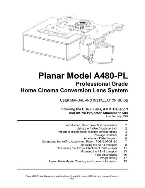
AKPro system with ATH1<br />
transport shown<br />
<strong>Planar</strong> Model A480-PL<br />
Professional Grade<br />
Home Cinema Conversion Lens System<br />
USER MANUAL AND INSTALLATION GUIDE<br />
Including the UH480 Lens, ATH1 Transport<br />
and AKPro Projector Attachment Kits<br />
As of February, 2009<br />
Introduction, Basic projection parameters<br />
Using the AKPro Attachment Kit<br />
Important ceiling mount location considerations<br />
Package Contents<br />
Attachment Plate Diagram<br />
Connecting the AKPro Attachment Plate – PD8130/PD8150<br />
Mounting the ATH1 transport<br />
Connecting the AKPro Attachment Plate – Viper<br />
Mounting the ATH1 transport<br />
Final adjustments<br />
Programming<br />
Aspect Ratio Matrix, Cleaning and Contact information<br />
<strong>Planar</strong> A480-PL User Manual and Installation Guide, Version 2.3, copyright 2009, all rights reserved, <strong>Planar</strong> Inc.<br />
Page 1<br />
2<br />
2<br />
3<br />
4<br />
6<br />
7<br />
8<br />
11<br />
13<br />
16<br />
17<br />
19
INTRODUCTION<br />
Thank you for purchasing the <strong>Planar</strong> A480-PL lens system – the world’s leading model<br />
anamorphic lens system designed to dramatically enhance today’s high performance 16:9<br />
projectors when showing the true widescreen aspect ratio of most major motion pictures.<br />
The A480-PL lens system includes the UH480 Lens and ATH1 automated transport to provide<br />
the optimum performance when viewing all wide screen content. The ATH1 transport can be<br />
mounted to your ceiling, to an improvised ceiling structure, or to the pre-engineered AKPro<br />
Attachment Kit. However, due to the very simple Plug-and-Play procedure they offer, use of<br />
these kits will be the focus of this installation guide.<br />
UH480 BASIC PROJECTION PARAMETERS<br />
Throw Distance (distance from projector lens to screen)<br />
This distance should be between 12 and 25 feet (3.6M and 7.6M) with the<br />
standard UH480 lens with an ideal range of 14.5 to 17.5 feet (4.4M to 5.3M) for the<br />
highest pixel level clarity, especially for computer graphics applications at 1080<br />
resolution. If your projection system involves a significantly higher throw distance then<br />
we recommend purchasing an optional correction element (see www.panamorph.com) if<br />
you need graphic level performance.<br />
Throw Ratio (ratio of throw distance to 16:9 native image width)<br />
This ratio primarily impacts image distortion. To minimize the amount that the<br />
image edges bow inward a throw ratio of at least 1.6 is recommended.<br />
If larger distortion is acceptable, the large aperture of the UH480 will generally<br />
work with a throw ratio as low as 1.3 as long as the beam passes through the lens<br />
unobstructed. Due to the large distortion and also the increased non-uniformity of image<br />
brightness (hot spotting) at very low throw ratios you may wish to consider a curved<br />
screen in such cases to help compensate for these artifacts.<br />
Image/Lens Shift<br />
Horizontal lens/image shift other than fine adjustment is not recommended due to<br />
keystoning that can be introduced by the UH480. Vertical lens shift does not impact the<br />
use of the UH480. However, note that with vertical lens shift the UH480 should be tilted<br />
to face the approximate center of the screen to make any residual pincushion distortion<br />
symmetric at the top and bottom of the image.<br />
A NOTE ON YOUR SCREEN FORMAT<br />
The A480-PL system works very well with a 2.35:1 aspect ratio screen. However, if you are<br />
considering a new screen we actually recommend an aspect ratio of 2.40:1 for the best all<br />
around fit. The 2.35:1 aspect ratio is somewhat of a film industry designation for many aspect<br />
ratios around 2.35:1 and may include many titles up to 2.40:1 and occasionally higher.<br />
Consequently, by following these installation instructions we will help you optimize your constant<br />
height imaging performance for all three primary aspect ratios of 16:9, 1.85:1 and the general<br />
range of 2.35:1-2.40:1.<br />
<strong>Planar</strong> A480-PL User Manual and Installation Guide, Version 2.3, copyright 2009, all rights reserved, <strong>Planar</strong> Inc.<br />
Page 2
USING the AKPro <strong>ATTACHMENT</strong> KIT<br />
The AKPro includes a high performance, rigid, solid steel plate specifically designed to attach to<br />
a properly installed ceiling mount head made by Chief Manufacturing (for use with the<br />
PD8130/8150) or Premier (for use with the PD8130/8150 and Viper), which may then be further<br />
installed to the ceiling using a variety of standard Chief or Premier mounting components.<br />
These components are not included in the kit but are available. The ceiling mounts and<br />
associated hardware must be installed to ceiling structural members to support at least<br />
250 pounds and must be extremely rigid. Any play in the ceiling mount will result in a<br />
rocking of the AKPro assembly as the lens moves in and out of the projector beam and<br />
represents a danger to equipment and personnel.<br />
The AKPro Attachment kit may also be used with a projector mount, but you must ensure that<br />
the mount is suited to support the total weight. If you wish to use a different projector mount the<br />
lens system is stabilized by using two chains extending from the front area of the plate to ceiling<br />
attachment points. You may skip ahead to Page 6 and the section titled: “Alternate<br />
Attachment Plate Method”<br />
IMPORTANT CEILING MOUNT LOCATION CONSIDERATIONS<br />
For optimum imaging results consult the projector’s instructions for the ceiling mount location to<br />
place the projector’s lens in the horizontal center (ie left to right) of your projection screen (even<br />
if the projector has a horizontal lens/image shift capability). In addition, make sure you are not<br />
at the limits of your projector’s zoom capability so that you have some range for image<br />
adjustments.<br />
The AKPro attachment plate is designed so that the projector and other attached components<br />
form an average center of mass (gravity) approximately located at the center of the ceiling<br />
mount pipe. Therefore, the ideal ceiling mount location will be shifted by the AKPro 2”<br />
(50mm) toward the left side of the screen from the ceiling mount location indicated by your<br />
projector’s instructions.<br />
If your projector ceiling mount is already installed and you do not wish to move it (or similarly<br />
move the screen in the opposite direction) due to a shift by the AKPro system, then you can<br />
make fine horizontal shift adjustments to your projector (if available) combined with turning the<br />
projector (only as necessary) during final setup to compensate for the shift. Some small amount<br />
of image distortion (horizontal keystoning) may result but in most cases this will not be<br />
noticeable since the image edges will typically be masked by the screen borders.<br />
WARNING!<br />
Use extreme caution and appropriate hardware when installing heavy objects to a<br />
ceiling. Periodically check all fasteners and connection hardware to be sure they are<br />
not coming loose. Improper installation may lead to an increased risk of your<br />
equipment becoming unstable and possibly injuring someone.<br />
<strong>Planar</strong> A480-PL User Manual and Installation Guide, Version 2.3, copyright 2009, all rights reserved, <strong>Planar</strong> Inc.<br />
Page 3
PACKAGE CONTENTS<br />
AKPro attachment plate, AKPro attachment bag (hardware, spacers), plate hook bag (chain,<br />
hooks, hardware)<br />
Transport, transport mounting hardware, lens bracket mounting hardware, power supply,<br />
Panamorph remote, batteries<br />
<strong>Planar</strong> A480-PL User Manual and Installation Guide, Version 2.3, copyright 2009, all rights reserved, <strong>Planar</strong> Inc.<br />
Page 4
Panamorph lens and mounting bracket<br />
Chief RPA ceiling mount (PD81xx use only)<br />
<strong>Planar</strong> A480-PL User Manual and Installation Guide, Version 2.3, copyright 2009, all rights reserved, <strong>Planar</strong> Inc.<br />
Page 5
3<br />
11<br />
6 15<br />
6<br />
1 13<br />
Rear<br />
7<br />
Top View (this side towards ceiling)<br />
Front<br />
H H<br />
13<br />
<strong>Planar</strong> A480-PL User Manual and Installation Guide, Version 2.3, copyright 2009, all rights reserved, <strong>Planar</strong> Inc.<br />
Page 6<br />
11<br />
H<br />
Ceiling side of<br />
Attachment Plate<br />
8130/8150 8130/8150<br />
7170 7170<br />
8130/8150 8130/8150<br />
7170 7170
PD8130/PD8150 installation instructions<br />
CONNECTING THE AKPro <strong>ATTACHMENT</strong> <strong>PLATE</strong><br />
(Chief RPA mount and Phillips screwdrivers required)<br />
1. Position the projector bottom-up on a soft surface. Consult the Attachment Plate<br />
Diagram for plate orientation, mounting hole locations and required screws and spacers<br />
for the PD8130 or PD8150. Insert and tighten each M4x30 screw through an<br />
appropriate silver washer and lock washer, the designated holes in the Attachment<br />
Plate, then through the 5/8” nylon spacers and finally into the projector ceiling mount<br />
holes.<br />
2. Using the included gold hex key, install the six 7/8” socket head screws each through a<br />
3/8” aluminum spacer and into the six threaded holes from the ceiling side of the<br />
attachment plate. Thread only enough to extend the screw to the bottom of the plate.<br />
<strong>Planar</strong> A480-PL User Manual and Installation Guide, Version 2.3, copyright 2009, all rights reserved, <strong>Planar</strong> Inc.<br />
Page 7
MOUNTING THE ATH1 TRANSPORT<br />
1. DO NOT CONNECT POWER TO THE TRANSPORT AT THIS TIME.<br />
2. Position the flat side of the<br />
motorized transport against the bottom<br />
side of the Attachment Plate so that the<br />
transport logo is toward the screen and<br />
the center “M” hole in the Attachment<br />
Plate is aligned with the front recessed<br />
transport hole. Insert the #10-32 pivot<br />
screw up through the transport and<br />
Attachment Plate and loosely complete<br />
the assembly with the corresponding<br />
washer, lock washer and nut. Now<br />
loosely insert the four small 3/8” screws<br />
ATH1/M380 Attachment Bag Contents<br />
#10-32x5/8” screw (1)<br />
#10-32 lock washer (1)<br />
#10-32 washer (1)<br />
#6-32x3/8” screw (4)<br />
through the four remaining “M” slots through the top of the Attachment Plate and down into the<br />
transport.<br />
M hole M slots<br />
#10-32 nut (1)<br />
ATH1 mount<br />
3. Refer to the ATH1 user manual (included with ATH1) for additional instructions to install<br />
the lens at this time, but do not forget to complete the “Final Adjustments” step below.<br />
ATTACHING THE PROJECTOR TO THE CEILING MOUNT<br />
Pivot screw as<br />
assembled<br />
Insure that the RPA mount head is secure (see instructions included with the RPA mount) and<br />
oriented properly relative to the 7/8” socket head screw heads so that the mounted projector will<br />
face the screen. Use two people to lift and position the projection assembly so that the heads of<br />
each of the 7/8” socket head screws rest within the matching final location of the RPA mount<br />
head. At this point the silver 3/8” spacers should be between the Attachment Plate and the RPA<br />
mount head. The projection assembly may be lowered to allow the 7/8” screw heads to rest on<br />
the RPA mount. However, a first person should continue to guide the projection assembly while<br />
and a second person uses the gold assembly wrench to tighten the 7/8” screws. When<br />
tightening these screws, do so in a pattern of incrementally driving each screw a little more into<br />
the attachment plate so that at any time the projection assembly is resting on as many screw<br />
heads as possible until all are tightened.<br />
<strong>Planar</strong> A480-PL User Manual and Installation Guide, Version 2.3, copyright 2009, all rights reserved, <strong>Planar</strong> Inc.<br />
Page 8<br />
Attachment<br />
Plate
<strong>Planar</strong> A480-PL User Manual and Installation Guide, Version 2.3, copyright 2009, all rights reserved, <strong>Planar</strong> Inc.<br />
Page 9
If the lens must be removed for any length of time it is recommended that a similar weight be<br />
suspended from the front of the attachment kit to balance the weight of the projector. This will<br />
minimize unusual stresses on the ceiling mount system.<br />
Proceed to “Final Adjustments” later on in this manual.<br />
<strong>Planar</strong> A480-PL User Manual and Installation Guide, Version 2.3, copyright 2009, all rights reserved, <strong>Planar</strong> Inc.<br />
Page 10
Viper (PD7170) installation instructions<br />
CONNECTING THE AKPro <strong>ATTACHMENT</strong> <strong>PLATE</strong> AND<br />
CEILING MOUNT<br />
(<strong>Planar</strong>/Premier PDS mount P/N 997-5351-00 and Phillips screwdrivers required)<br />
1. Position the projector bottom-up on a soft surface. Consult the Attachment Plate<br />
Diagram for plate orientation, mounting hole locations and required screws and spacers<br />
for the Viper. Align the bottom part of the <strong>Planar</strong>/Premier PDS mount with the<br />
attachment plate holes and insert and tighten each M4x30 screw through an appropriate<br />
silver washer and lock washer, the designated holes in the Attachment Plate, then<br />
through the 5/8” nylon spacers and finally into the projector ceiling mount holes.<br />
<strong>Planar</strong> A480-PL User Manual and Installation Guide, Version 2.3, copyright 2009, all rights reserved, <strong>Planar</strong> Inc.<br />
Page 11
VIPER (PD7170) <strong>ATTACHMENT</strong> SECURITY HOOK<br />
<strong>ATTACHMENT</strong><br />
(Phillips screwdrivers, pliers, scissors and appropriate ceiling hooks required)<br />
Plate Hook Bag Contents (AK6 only)<br />
3/16” Chain (6 feet) Chain End (4)<br />
1. Install the Plate Hook Assemblies in the two “H”<br />
holes of the Attachment Plate (see diagram) with the<br />
hook ends on the ceiling side as shown above. Use<br />
pliers to bend the closed hooks apart just enough to<br />
install a Chain End at a later time.<br />
#8-32 Wire Hook (2)<br />
#8-32 Nut (4)<br />
#8 Washer (4)<br />
M4 Lock Washer (2)<br />
Attachment<br />
Screws<br />
Spacers<br />
2. Install ceiling hooks (not supplied) into the ceiling<br />
directly above the Plate Hooks. The ceiling hooks<br />
should be small enough to accept a Chain End<br />
but strong enough when installed to each support 40 pounds or more.<br />
Plate Hook<br />
as assembled to<br />
Attachment Plate<br />
5. Attach a Chain End to the Chain and then connect to one of the ceiling hooks. Cut the Chain<br />
and assemble to another Chain End for a best fit to the corresponding Plate Hook and attach.<br />
Repeat for the other set of hooks.<br />
<strong>Planar</strong> A480-PL User Manual and Installation Guide, Version 2.3, copyright 2009, all rights reserved, <strong>Planar</strong> Inc.<br />
Page 12<br />
Ceiling<br />
side<br />
Ceiling Mount<br />
adapter<br />
Attachment<br />
Plate
MOUNTING THE ATH1 TRANSPORT<br />
1. DO NOT CONNECT POWER TO THE TRANSPORT AT THIS TIME.<br />
2. Position the flat side of the<br />
motorized transport against the bottom<br />
side of the Attachment Plate so that the<br />
transport logo is toward the screen and<br />
the center “M” hole in the Attachment<br />
Plate is aligned with the front recessed<br />
transport hole. Insert the #10-32 pivot<br />
screw up through the transport and<br />
Attachment Plate and loosely complete<br />
the assembly with the corresponding<br />
washer, lock washer and nut. Now<br />
loosely insert the four small 3/8” screws<br />
ATH1/M380 Attachment Bag Contents<br />
#10-32x5/8” screw (1)<br />
#10-32 lock washer (1)<br />
#10-32 washer (1)<br />
#6-32x3/8” screw (4)<br />
through the four remaining “M” slots through the top of the Attachment Plate and down into the<br />
transport.<br />
M hole M slots<br />
#10-32 nut (1)<br />
ATH1 mount<br />
Pivot screw as<br />
assembled<br />
3. Refer to the ATH1 user manual (included with ATH1) for additional instructions to install the<br />
lens at this time, but do not forget to complete the “Final Adjustments” step below.<br />
<strong>Planar</strong> A480-PL User Manual and Installation Guide, Version 2.3, copyright 2009, all rights reserved, <strong>Planar</strong> Inc.<br />
Page 13<br />
Attachment<br />
Plate
ATTACHING THE PROJECTOR TO THE CEILING MOUNT<br />
Follow the instructions included in the PDS mount to securely attach it to the ceiling<br />
Attach the projector to the ceiling mounted portion of the PDS mount<br />
<strong>Planar</strong> A480-PL User Manual and Installation Guide, Version 2.3, copyright 2009, all rights reserved, <strong>Planar</strong> Inc.<br />
Page 14
<strong>Planar</strong> A480-PL User Manual and Installation Guide, Version 2.3, copyright 2009, all rights reserved, <strong>Planar</strong> Inc.<br />
Page 15
FINAL ADJUSTMENTS (ALL INSTALLATIONS)<br />
1. Turn the projector on with the UH480 Lens out of the projector beam. Set the horizontal<br />
lens shift to neutral (if a feature of your projector) and then adjust the ceiling mount so that the<br />
16:9 image is in the exact center of and square to the screen, with a similar amount of image<br />
slightly over the top and bottom screen borders. If the projector lens is not in the exact<br />
horizontal center of the screen you may need to use a little horizontal lens shift for this purpose.<br />
2. Bring the UH480 Lens into the beam. Adjust the vertical position and tilt of the Lens so<br />
that the projector beam is passing through the center of the Lens and so any residual<br />
pincushion distortion is about the same at the top and bottom of the image. This will typically<br />
result in the UH480 Lens being below the center of the projector lens and tilted slightly<br />
downward. Tighten the knobs.<br />
3. Adjust the rotation of the ATH1 transport so that the left and right sides of the image are<br />
an equal distance from their respective screen borders. Now tighten the Pivot Screw (M380)<br />
and also the four remaining screws holding the transport to the Attachment Plate.<br />
4. For optimum multiple aspect ratio performance, adjust the projector’s zoom so that a<br />
1.85:1 aspect ratio movie (Lens “out”) is just masked by the top and bottom of the screen<br />
border. This way 1.85:1, 16:9 and 2.35-2.4:1 aspect ratio movies should all be presented to fill<br />
the screen at a constant height.<br />
5. Remove the protective film from the front of the Panamorph lens<br />
<strong>Planar</strong> A480-PL User Manual and Installation Guide, Version 2.3, copyright 2009, all rights reserved, <strong>Planar</strong> Inc.<br />
Page 16
Programming<br />
Connect the included power adapter to the power input and connect a 3.5mm mini jack to<br />
3.5mm mini jack cord that is long enough to reach from the Panamorph transport motor to the<br />
rear of the <strong>Planar</strong> projector (not included) to the “+12V Trigger In” on the Panamorph transport<br />
motor<br />
Plug the other end of the 3.5mm mini jack into one of the two 12V triggers located on the rear<br />
panel of the projector.<br />
With the lens in the “out” position, bring up the projector menu. Navigate to the “Control” tab and<br />
select “Letterbox” for the trigger that you attached 3.5mm cable from the Panamorph transport.<br />
<strong>Planar</strong> A480-PL User Manual and Installation Guide, Version 2.3, copyright 2009, all rights reserved, <strong>Planar</strong> Inc.<br />
Page 17
Now when the aspect on the projectors aspect ratio is changed to “Letterbox”, the 12V trigger<br />
will activate and the Panamorph lens transport will position the Panamorph lens in front of the<br />
projectors primary lens.<br />
<strong>Planar</strong> A480-PL User Manual and Installation Guide, Version 2.3, copyright 2009, all rights reserved, <strong>Planar</strong> Inc.<br />
Page 18
Aspect Ratio Matrix<br />
Native Source<br />
Aspect<br />
Projector Aspect and<br />
12V trigger Setting with<br />
Panamorph Lens<br />
Resulting Aspect<br />
on Screen<br />
16:9 4:3 16:9<br />
16:9 letterbox Letterbox 2.35:1<br />
4:3 4:3 Narrow 4:3<br />
You can program the projector control the lens and screen mask for one resize mode, such as<br />
16:9 letterbox to 2.35:1, or leave the Panmorph lens in front of the lens all the time and adjust<br />
the aspect raito per source type.<br />
CLEANING<br />
In most applications lenses do not need very much cleaning – a bit of dust will not impact image<br />
clarity. However, in today’s high performance home cinemas with very dark rooms a small<br />
build-up of dust or other foreign matter on your projector lens or your Panamorph lens can<br />
produce a measurable reduction in contrast. The most effective cleaning approach is to simply<br />
blow off any dust. If there is any residue or build-up then it is recommended that you clean the<br />
optics with professional lens cleaning supplies such as from a camera store while the lens is in<br />
front of the lit beam of the projector. This will allow you to quickly see both the results of<br />
cleaning and also if you are causing any damage.<br />
<strong>Planar</strong> Systems<br />
1195 NW Compton Drive<br />
Beaverton, OR, 97006<br />
http://www.planar.com<br />
<strong>Planar</strong> A480-PL User Manual and Installation Guide, Version 2.3, copyright 2009, all rights reserved, <strong>Planar</strong> Inc.<br />
Page 19