ASSEMBLY FITTING INSTRUCTIONS FOR ... - CMP Products
ASSEMBLY FITTING INSTRUCTIONS FOR ... - CMP Products
ASSEMBLY FITTING INSTRUCTIONS FOR ... - CMP Products

You also want an ePaper? Increase the reach of your titles
YUMPU automatically turns print PDFs into web optimized ePapers that Google loves.
TECHNICAL DATACABLE GLAND TYPEINGRESS PROTECTIONCABLE TYPE (S): PXSS2K: IP66, IP67, IP68: UNARMOUREDPROCESS CONTROL SYSTEM : BS EN ISO 9001 - 2000HAZARDOUS AREA CLASSIFICATIONATEX / CENELEC APPROVAL : ATEX II 2 GD Ex d IIC, Ex e II, Ex nR II, Ex tD A21 IP66 - Equipment Zone 1, Zone 2, Zone 21, & Zone 22 - GasGroups IIA, IIB, IIC, ATEX IM2, Exd I / Ex e ICOMPLIANCE CODE : EN 60079-0: 2004, EN 60079-1: 2004, EN 60079-7: 2003, EN 60079-15: 2003, EN 61241-0: 2004 EN 61241-1: 2004ATEX CERTIFICATION DETAIL : II 2/3 GD - SIRA06ATEX1097XSPECIAL CONDITIONS <strong>FOR</strong> SAFE USE• These Cable Glands shall not be used where the temperature at the point of mounting is below -60°C or exceeds 100°C.• These Cable Glands are only suitable for fixed installations cables must be effectively clamped to prevent pulling or twisting• The entry thread component may need additional sealing to maintain the IP rating as applicable to the associated equipment to which thecable gland will be attached.ACCESSORIESThe following accessories are available from <strong>CMP</strong> <strong>Products</strong>, as optional extras, to assist with fixing, sealing and earthing :-Locknut | Earth Tag | Serrated Washer | Entry Thread (I.P.) Sealing Washer | Shroud *CORRECT TOOLSAlways use the correct tools, as incorrect tools will inevitably lead to mistakes, potential damage and/or personal injury. Gloves are recommended whenhandling and terminating cables and cable glands.Dedicated Cable Gland spanners for each cable gland size are available from <strong>CMP</strong> <strong>Products</strong>, and these are recommended for installing the productcorrectly. Adjustable spanners and wrenches are not recommended as there is a possibility of slippage that can lead to accidental injury or damage tosurface finish.Any sharp tools, instruments or knives used to cut or strip the cable sheath should be equipped with a safety blade or other safety feature consistent withthe tool design and intended use.Please refer to <strong>CMP</strong> <strong>Products</strong> in sourcing tools if required, who would be happy to assist.Safety and personal protection should be given priority over all other considerations.SIRA06ATEX1097X – 0518Ex d IIC/Ex e II/Ex nR II/Ex d 1/Ex e 1Category 2/3 GD IP66, IP67, IP68Deluge Protection – DTS01 : 91IECEx SIR 06.0044XEx d IIC/Ex e II/Ex nR II/Ex tD A21 IP66/Ex d 1/Ex e 1To IEC 60079-0:2004, 60079-1:2003, 60079-7:2001,60079-15:2005, 61241-0:2004, 61241-1:2004GOST APPROVAL : POCC GB 05.B01912ZONE I, Ex d IIC U & Ex e II UTO : 51330.0-99 / 52350.0-2005 /52350.1-2005 / 51330.8-99 /52350.7-2005.LLULLUUL LISTED TO UL514B, UL 886,UL 2225, & UL2227<strong>FOR</strong> ORDINARY, WET &HAZARDOUS LOCATIONSFILE REFERENCE E161256MARINE APPROVALSABS : 01-LD 234401A/1-PDALLOYDS REGISTER SHIPPING (LRS) : 01/00172DET NORSKE VERITAS (DNV) : E-8119cUL LISTED TO UL514B, UL 886 UL 2225, & UL2227<strong>FOR</strong> ORDINARY, WET & HAZARDOUS LOCATIONSCLASS I, DIV 2, ABCD, CLASS II, DIV 2, F & GFILE REFERENCE E201187<strong>ASSEMBLY</strong> <strong>FITTING</strong> <strong>INSTRUCTIONS</strong> <strong>FOR</strong> INSTALLATIONOF <strong>CMP</strong> CABLE GLAND TYPE PXSS2K<strong>FOR</strong> TERMINATION OF UNARMOURED & BRAIDED CABLES, AND INTENDED <strong>FOR</strong> USE IN POTENTIALLYFLAMMABLE ATMOSPHERES (HAZARDOUS AREAS)INCORPORATING EC DECLARATION OF CON<strong>FOR</strong>MITY TO DIRECTIVE 94/9/ECGENERAL INSTALLATION GUIDANCE• BS EN 60079 -10 Classification of Hazardous Areas• BS EN 60079 -14 2003 Electrical Installations in Hazardous Areas (other than mines). Please refer to the selection guide in clause 10.4.2 for Ex d applications.• Installation should only be carried out by a competent person, skilled in the installation of cable glands• Care should be taken to avoid damage to entry threads when handling and installing cable glands• Depending upon the specific form of protection of the main equipment it may be necessary to fit an I.P. sealing washer, at the cable entry interface, tomaintain the appropriate Ingress Protection levels. For Increased Safety (Ex e) equipment, or Increased Safety terminal chambers found on Ex deequipment, a sealing washer is essential to maintain the minimum Ingress Protection rating, and should always be fitted. For other forms of protection,e.g. Flameproof Ex d apparatus, the inclusion of a sealing washer is optional. <strong>CMP</strong> (I.P.) Sealing Washers, which are installed at the cable entry interface,between the equipment enclosure and the cable entry device (cable gland) have been 3rd party tested in Ingress Protection tests to BS EN 60529• Always ensure that the correct fixing accessories provided by <strong>CMP</strong> <strong>Products</strong> are used, as appropriate to secure the cable glands into the matingequipment. In addition to (I.P.) Sealing Washers, <strong>CMP</strong> <strong>Products</strong> are also able to provide Locknuts, Earth Tags, and Serrated Washers which should be usedas appropriate to the equipment configuration. Usually for any equipment other than Ex d apparatus, it will be necessary to use as a minimum a Locknut,and also a Serrated Washer if the enclosure of the equipment or application requires it.The addition of an Earth Tag will depend upon the earthcontinuity provision of the enclosures installed.• Cable Gland seals are included within the cable gland when despatched from the factory.There should be no circumstances where seals need to beremoved from the cable gland. Care should be taken to avoid exposure of cable gland seals to dirt, hostile substances, e.g. solvents, and other foreignbodies.• Cable Gland components are not interchangeable with those of any other cable gland manufacturer. It is important to note that components from onemanufacturer's product cannot be used in that of another, and that modification of a cable gland product will invalidate the hazardous area certification.• The cable gland is not a user serviceable product and spare parts are not permitted to be supplied under the certification.<strong>CMP</strong> Document No. FI262 Issue 2 12/07• Cable Glands should not be installed whilst circuits are live. Similarly, following energising of the electrical circuits, cable glands should not be dismantledor opened until the circuit has been safely de-energised.I, the undersigned, hereby declare that the equipment referred to herein conforms to 94/9/EC directive.Dr Geof Mood - Technical Director(Authorised Person)0518Notified Body: Sira Certification Service, Rake Lane, Chester CH4 9JN, England.Glasshouse Street • St. Peters • Newcastle upon Tyne • NE6 1BSTel: +44 191 265 7411 • Fax: +44 191 265 0581E-Mail: cmp@cmp-products.co.uk • Web: www.cmp-products.com<strong>CMP</strong> Document No. FI262 Issue 2 12/07
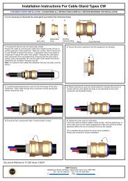
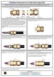
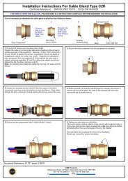
<strong>ASSEMBLY</strong> <strong>FITTING</strong> <strong>INSTRUCTIONS</strong> <strong>FOR</strong>INSTALLATION OF CABLE GLAND TYPE PXSS2K<strong>CMP</strong> type PXSS2K Triple certified flameproof (type "d"),Increased Safety(type "e"), and Restricted Breathing(type nR) also Class I Division 2 CableGland (connector) for all types of Unarmoured Cables providing an environmental seal on the cable outer sheath and a Flameproof (or Explosionproof) compound barrier seal to the individual inner cable cores. Suitable for use in Zone 1, Zone 2, Zone 21 and Zone 22 Hazardous Areas.CABLE GLAND COMPONENTS1. Compound2. Entry Component‘A’3. Compound Tube4. Tube Spacer5. ‘O’ Ring6. Main Item7. Skid Washer8. Outer Seal9. Outer Seal Nut12 3 4 5 6 7 8 9The following instructions should be followed when terminating barrier type cableglands onto cables containing Drain Wire/s.A) When Using Drain Wire/s with heat/cold shrink tubingi) Proceed with steps 1 to 6 of the installation instructions opposite, with thefollowing additional steps.ii)iii)Apply the compound into the crutch of the cable for a distance ofapproximately 6mm.Push a 100mm minimum length of heat shrink sleeve over the Drain Wire/sto butt against the epoxy putty compound.iv) Apply heat to gently shrink the sleeve evenly around the wire to extrude allair.Entry Component ‘A’5 6 7 8 92 3 4 Sub-Assembly ‘B’PLEASE READ <strong>INSTRUCTIONS</strong> CAREFULLY BE<strong>FOR</strong>E BEGINNING INSTALLATION1. Separate gland assembly as shown in fig 1. Entry Component ‘A’ and Sub-Assembly ‘B’NOTE :- Items 3 and 4 are loose components.2. Determine the conductor length required to suit the equipment geometry and pass sub-assembly ‘B’ over the cable, seal nut (9) first,locating it in the desired position. Hold the main item (6) and tighten seal nut (9) to seal Sub-Assembly ‘B’ onto the cable.3. Remove the outer cable sheath at point ‘X’ to suit (fig 2), and then carefully remove any bedding, fillers or tapes from around theconductors, in readiness for application of epoxy resin barrier compound, avoiding damage to the conductor insulation.4. Pass the tube spacer (4) over the conductors and locate in main item (6).5. It is important that the compound is correctly mixed and applied as this will form the flameproof or (explosion proof) seal.Thoroughlymix the two part compound in equal proportions to a uniform colour and a soft pliable consistency. Plastic gloves are provided forpersonal protection whilst handling the compound.6. For Drain Wire terminations see further instructions opposite, or otherwise if no drain wires present continue with step 7 below.7. Separate the conductors and pack compound into the crutch of the cable, between and around the conductors. Bring the conductorsback together, and apply the compound further around the cable conductors to a diameter sufficient to fill the tube spacer (4) andcompound tube (3).The compound should be applied around and between the conductors to a length not exceeding that of thecompound tube (3), ending in a taper (minimum length of filled compound 20mm) (fig 3).8. Pass the compound tube (3) over the conductors and compound, and push it firmly until it is fully located with the tube spacer (4) (fig4). Pack the compound into the end of the compound tube (3) ensuring that it is filled completely. Remove any excess compound fromall external surfaces to ensure that the components can be assembled without obstruction, and that the flameproof paths are notimpaired.9a. Direct makeoff into Equipmenti) Secure Entry Component ‘A’ (2) into the equipment.ii) Slacken the outer seal nut (9) to ensure that the seal is relaxed.iii) Carefully pass the cable assembly through the Entry Component ‘A’ (2) ensuring that the compound is not disturbed.iv) With the compound tube located in the Entry Component ‘A’ (2) tighten main item (6) into Entry component ‘A’ (2).v) Using a standard spanner, tighten the Outer Seal Nut (9) onto the main item (6) until it comes to an effective stop.This will occur when i.The Outer Seal Nut (9) is metal to metal with the main item (6) of the cable gland, or ii. The Outer Seal has clearly engaged the cable andcannot be further tightened without the use of excessive force by the installer.vi) The cable gland must be left to cure undisturbed, until the compound has hardened before the cable conductors are terminated.9b. Remote make offi) Carefully pass the Entry Component ‘A’ (2) over the cable assembly ensuring that the compound is not disturbed.ii) With the compound tube (3) located in the Entry Component ‘A’ (2) carefully tighten the Entry Component ‘A’ (2) and main item(6) together to complete the cable gland assembly in true alignment.iii) The cable gland must be left to cure undisturbed, until the compound has hardened.iv) After the compound has cured, dismantle the assembly by reversing step ii. above, remove the Entry Component ‘A’ (2) and securethis into the equipment.v) Ensure that the outer seal nut (9) is relaxed.vi) Carefully pass the cable assembly through the Entry Component ‘A’ (2).vii) With the compound tube located in the Entry Component ‘A’ (2) tighten main item (6) onto Entry Component ‘A’ (2).viii) Using a standard spanner, tighten the Outer Seal Nut (9) onto the main item (6) until it comes to an effective stop.This will occur when i.The Outer Seal Nut (9) is metal to metal with the main item (6) of the cable gland, or ii. The Outer Seal has clearly engaged the cable andcannot be further tightened without the use of excessive force by the installer.This completes the termination.v) Continue with step 7 of the installation instructions opposite.B) When insulating Drain Wire/s or Screens with separateinsulated connectioni) Proceed with steps 1 to 6 of the installation instructions opposite, with thefollowing additional steps.ii)When cable is provided with screen wires remove a further 15mm ofouter sheathing to expose the screens.iii) Unravel the screen wires and twist together to form one single conductor.It may be necessary to cut out and remove some of the screen wires priorto the next step.iv)Crimp or solder an insulated conductor to the screen conductor by the useof an insulated butt ferrule.The length of the insulated conductor will bedetermined by the distance to the point of the earth connection within theequipment.v) IMPORTANT, there must be a minimum of 10mm of the epoxy resincompound applied both before and after the crimped connection.vi)CableGlandSizeContinue with step 7 of the installation instructions opposite.Cable Gland Selection TableAvailable Entry ThreadsStandardOptionMinimumThreadLengthDiameterOverConductorsNumber ofCoresOverall CableDiameterAcrossFlatsAcrossCornersMetric NPT NPT Max Max Min Max Max MaxNominalProtrusionLengthOrderingReference(Brass Metric)#PVCShroudReference*20S/16 M20 1/2” 3/4” 15.0 12.6 15 3.0 8.7 30.5 33.3 58.5 20S16PXSS2K1RA PVC04 0.20020S M20 1/2” 3/4” 15.0 12.6 15 6.1 11.7 30.5 33.3 58.5 20SPXSS2K1RA PVC04 0.20020 M20 1/2” 3/4” 15.0 12.6 15 6.5 14.0 30.5 33.3 60.5 20PXSS2K1RA PVC05 0.25025 M25 3/4” 1” 15.0 17.5 29 11.1 20.0 37.5 40.5 67.5 25PXSS2K1RA PVC09 0.40332 M32 1” 1-1/4” 15.0 23.6 51 17.0 26.3 46.0 51.0 69.5 32PXSS2K1RA PVC10 0.55540 M40 1-1/4” 1-1/2” 15.0 30.0 80 22.0 32.1 55.0 61.0 78.0 40PXSS2K1RA PVC13 0.60050S M50 1-1/2” 2” 15.0 36.6 122 29.5 38.2 60.0 66.5 75.5 50SPXSS2K1RA PVC15 0.60550 M50 2” 2-1/2” 15.0 41.0 149 35.6 44.1 70.0 78.6 80.5 50PXSS2K1RA PVC18 0.62063S M63 2” 2-1/2” 15.0 47.9 205 40.1 50.1 75.0 83.2 91.5 63SPXSS2K1RA PVC21 0.70563 M63 2-1/2” 3” 15.0 53.7 259 47.2 56.0 80.0 89.0 92.0 63PXSS2K1RA PVC23 0.73075S M75 2-1/2” 3” 15.0 59.8 320 52.8 62.0 89.0 101.6 99.0 75SPXSS2K1RA PVC24 1.15075 M75 3” 3-1/2” 15.0 64.3 364 59.1 68.0 99.0 111.1 102.0 75PXSS2K1RA PVC26 1.30090 M90 3” 3-1/2” 15.0 75.3 500 66.6 79.4 114.0 128.6 120.0 90PXSS2K1RA PVC31 2.700All dimensions in millimetresCableGlandWeight(Kgs)