Installation Instructions For Cable Gland Types E2X - CMP Products
Installation Instructions For Cable Gland Types E2X - CMP Products
Installation Instructions For Cable Gland Types E2X - CMP Products
- No tags were found...

Create successful ePaper yourself
Turn your PDF publications into a flip-book with our unique Google optimized e-Paper software.
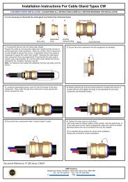
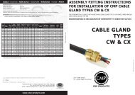
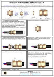
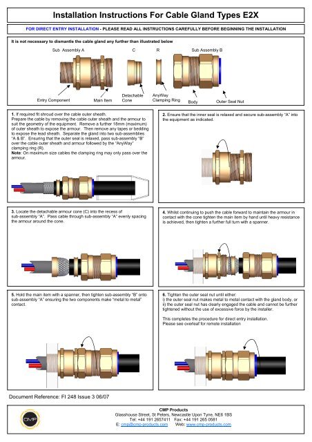
<strong>Installation</strong> <strong>Instructions</strong> <strong>For</strong> <strong>Cable</strong> <strong>Gland</strong> <strong>Types</strong> <strong>E2X</strong>FOR DIRECT ENTRY INSTALLATION - PLEASE READ ALL INSTRUCTIONS CAREFULLY BEFORE BEGINNING THE INSTALLATIONIt is not necessary to dismantle the cable gland any further than illustrated belowSub Assembly ACRSub Assembly BEntry ComponentMain ItemDetachableConeAnyWayClamping RingBodyOuter Seal Nut1. If required fit shroud over the cable outer sheath.Prepare the cable by removing the cable outer sheath and the armour tosuit the geometry of the equipment. Remove a further 18mm (maximum)of outer sheath to expose the armour. Then remove any tapes or beddingto expose the lead sheath. Separate the gland into two sub-assemblies“A & B”. Ensuring that the outer seal is relaxed, pass sub-assembly “B”over the cable outer sheath and armour followed by the “AnyWay”clamping ring (R).Note: On maximum size cables the clamping ring may only pass over thearmour.2. Ensure that the inner seal is relaxed and secure sub-assembly “A” intothe equipment as indicated.3. Locate the detachable armour cone (C) into the recess ofsub-assembly “A”. Pass cable through sub-assembly “A” evenly spacingthe armour around the cone.4. Whilst continuing to push the cable forward to maintain the armour incontact with the cone tighten the main item by hand until heavy resistanceis achieved, then tighten a further full turn with a spanner.5. Hold the main item with a spanner, then tighten sub-assembly “B” ontosub-assembly “A” ensuring the two components make “metal to metal”contact.6. Tighten the outer seal nut until either:i) the outer seal nut makes metal to metal contact with the gland body, orii) the outer seal nut has clearly engaged the cable and cannot be furthertightened without the use of excessive force by the installer.This completes the procedure for direct entry installation.Please see overleaf for remote installationDocument Reference: FI 248 Issue 3 06/07<strong>CMP</strong> <strong>Products</strong>Glasshouse Street, St Peters, Newcastle Upon Tyne, NE6 1BSTel: +44 191 2657411 Fax: +44 191 265 0581E: cmp@cmp-products.com Web: www.cmp-products.com
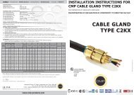
<strong>Installation</strong> <strong>Instructions</strong> <strong>For</strong> <strong>Cable</strong> <strong>Gland</strong> <strong>Types</strong> <strong>E2X</strong>FOR REMOTE INSTALLATION - PLEASE READ ALL INSTRUCTIONS CAREFULLY BEFORE BEGINNING THE INSTALLATION1. If required fit shroud over the cable outer sheath.Prepare the cable by removing the cable outer sheath and the armour tosuit the geometry of the equipment. Remove a further 18mm (maximum)of outer sheath to expose the armour. Then remove any tapes or beddingto expose the lead sheath. Separate the gland into two sub-assemblies“A & B”. Ensuring that the outer seal is relaxed, pass sub-assembly “B”over the cable outer sheath and armour followed by the “AnyWay”clamping ring (R).Note: On maximum size cables the clamping ring may only pass over thearmour.2. Locate the detachable armour cone (C) into the recess ofsub-assembly “A”. Pass cable through sub-assembly “A”, evenly spacingthe armour around the cone.3. Hold the main item with a spanner then tighten the sub-assembly “B”onto sub-assembly “A” ensuring the two components make “metal tometal” contact. Disconnect sub-assembly “B” from sub-assembly “A”4. Ensure that the inner seal is relaxed and secure sub-assembly “A” intothe equipment as indicated.5. Pass cable through sub-assembly “A”. Tighten the main item by handuntil heavy resistance is achieved, then tighten a further full turn with aspanner.6. Hold the main item with a spanner, then re-tighten the sub-assembly“B” onto sub-assembly “A” ensuring the two components are fullytightened.7. Tighten the outer seal nut until either:i) the outer seal nut makes metal to metal contact with the gland body, orii) the outer seal nut has clearly engaged the cable and cannot be furthertightened without the use of excessive force by the installer.This completes the procedure for remote installation.Document Reference: FI 248 Issue 3 06/07<strong>CMP</strong> <strong>Products</strong>Glasshouse Street, St Peters, Newcastle Upon Tyne, NE6 1BSTel: +44 191 2657411 Fax: +44 191 265 0581E: cmp@cmp-products.com Web: www.cmp-products.com