
Create successful ePaper yourself
Turn your PDF publications into a flip-book with our unique Google optimized e-Paper software.
DUBAI • HOUSTON • NEWCASTLE • SINGAPORE • SHANGHAI • PUSAN • PERTHTECHNICAL DATA<strong>CABLE</strong> <strong>GLAND</strong> <strong>TYPE</strong>: <strong>C2KX</strong>INGRESS PROTECTION: IP66, IP67, IP68PROCESS CONTROL SYSTEM : BS EN ISO 9001HAZARDOUS AREA CLASSIFICATIONATEX CERTIFICATION No: SIRA 06ATEX1097XATEX CERTIFICATION CODE : II 2 GD Ex e II / Ex tD A21 IP66IEC Ex CERTIFICATION No: IEC Ex SIR.06.0042XIEC Ex CERTIFICATION CODE : Ex e II / Ex tD A21 IP66CSA CERTIFICATION No : 2367109CSA CERTIFICATION CODE: Ex e II and Class I, Zone 1, AEx e IIINSTALLATION INSTRUCTIONSInstallation should only be performed by a competent person using the correct tools. Read all instructions before beginning installation.SPECIAL CONDITIONS FOR SAFE USEFor ATEX & IEC Ex certification:1. The cable gland ranges shall only be used where temperatures at the point of entry is between -60°C and +130°C.2. <strong>C2KX</strong> cable glands are only suitable for fixed installations. Cables must be effectivelu clamped to prevent twisting and pulling3. The entry component threads may need additional sealing to maintain the ingress protection rating as applicable to the associated equipment towhich it is attachedFor American Ex certification:1. <strong>C2KX</strong> cable glands are only suitable for fixed installations. Cables must be effectively clamped to prevent twisting and pulling.2. According to C.E.C. and the N.E.C. wiring method for the types of cables that can be used in Class I, Zone 1and 2 Classified Areas, accordingto 60079-14 installation wiring method restrictions.3. Shipboard Cables are for use on Marine Platform and/or shipboards only and are subject to local authorities having jurisdiction on the installation.ASSEMBLY FITTING INSTRUCTIONSFOR INSTALLATION OF <strong>CMP</strong> <strong>CABLE</strong><strong>GLAND</strong> <strong>TYPE</strong> <strong>C2KX</strong>FOR TERMINATION OF <strong>CABLE</strong>S WITH WIRE BRAID.INCORPORATING EC DECLARATION OF CONFORMITY TO DIRECTIVE 94/9/EC<strong>CABLE</strong> <strong>GLAND</strong><strong>TYPE</strong> <strong>C2KX</strong>ACCESSORIESThe following accessories are available from <strong>CMP</strong> <strong>Products</strong>, as optional extras, to assist with fixing, sealing and earthing :-Locknut | Earth Tag | Serrated Washer | Entry Thread (I.P.) Sealing Washer | Shroud *CableConnectorSizeAvailable Entry ThreadsStandardOptionThread LengthCableBeddingDiameterOverall CableDiameterArmor RangeAcrossFlatsAcrossFlatsProtrusionLengthOrdering Reference(NP Brass NPT)Metric NPT NPT Actual NPT Min Metric Max Min Max Min Max Min Max Max MaxPVCShroudReference*20S/16 1/2" 3/4" M20 0.630 0.591 0.461 0.240 0.453 0.000 0.039 0.945 1.021 2.303 20S16<strong>C2KX</strong>1RA531 PVC06 4.6520S 1/2" 3/4" M20 0.630 0.591 0.461 0.374 0.626 0.000 0.039 0.945 1.021 2.303 20S<strong>C2KX</strong>1RA531 PVC06 4.6520 1/2" 3/4" M20 0.630 0.591 0.551 0.492 0.823 0.000 0.039 1.201 1.112 2.382 20<strong>C2KX</strong>1RA531 PVC06 6.8425S 3/4" 1 M25 0.669 0.591 0.787 0.551 0.866 0.000 0.039 1.476 1.594 2.657 25S<strong>C2KX</strong>1RA532 PVC09 10.7825 3/4" 1" M25 0.669 0.591 0.787 0.717 1.031 0.000 0.039 1.476 1.594 2.657 25<strong>C2KX</strong>1RA531 PVC09 10.7832 1" 1 1/4" M32 0.787 0.591 1.035 0.933 1.335 0.000 0.039 1.811 2.008 2.736 32<strong>C2KX</strong>1RA532 PVC11 16.49ConnectorWeight(Ozs)40 1 1/4" 1 1/2" M40 0.787 0.591 1.268 1.098 1.591 0.000 0.039 2.165 1.956 3.071 40<strong>C2KX</strong>1RA534 PVC15 23.8950S 1 1/2" 2" M50 0.787 0.591 1.504 1.386 1.839 0.000 0.039 2.362 2.338 2.972 50S<strong>C2KX</strong>1RA535 PVC18 26.4350 2" 2 1/2" M50 0.906 0.591 1.736 1.591 2.091 0.000 0.039 2.756 2.827 3.169 50<strong>C2KX</strong>1RA536 PVC21 36.7963S 2" 2 1/2" M63 0.906 0.591 1.969 1.795 2.339 0.000 0.039 2.953 3.189 3.602 63S<strong>C2KX</strong>1RA536 PVC23 37.8563 2 1/2" 3" M63 0.984 0.591 2.205 2.150 2.594 0.000 0.039 3.150 3.402 3.622 63<strong>C2KX</strong>1RA537 PVC25 45.1175S 2 1/2" 3" M75 0.984 0.591 2.441 2.323 2.839 0.000 0.039 3.504 3.784 3.898 75S<strong>C2KX</strong>1RA537 PVC28 65.5575 3" 3 1/2" M75 1.417 0.591 2.677 2.262 3.091 0.000 0.039 3.898 4.209 4.016 75<strong>C2KX</strong>1RA538 PVC30 89.8790 3 1/2" 4" M90 1.417 0.591 3.150 3.000 3.559 0.000 0.063 4.488 4.847 4.724 90<strong>C2KX</strong>1RA539 PVC32 128.63Dimensions are displayed in inches unless otherwise stated<strong>CMP</strong> Document No. FI425 Issue 1 04/11NOTE: *<strong>CMP</strong> SOLO LSF Halogen Free Shrouds also available on request. # Other thread forms are available.I, the undersigned, hereby declare that the equipment referred to herein conforms to 94/9/EC directive.Dr Geof Mood - Technical Director - (Authorised Person)0518Notified Body: Sira Certification Service, Rake Lane, Chester CH4 9JN, England.Glasshouse Street • St. Peters • Newcastle upon Tyne • NE6 1BSTel: +44 191 265 7411 • Fax: +44 191 265 0581E-Mail: cmp@cmp-products.co.uk • Web: www.cmp-products.com<strong>CMP</strong> PRODUCTSwww.cmp-products.comLogo’s shown for illustration purposes only. Please check certification for details
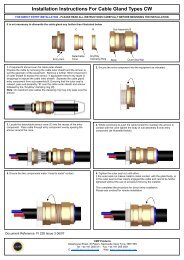
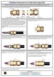
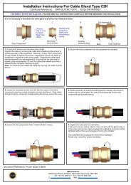
DUBAI • HOUSTON • NEWCASTLE • SINGAPORE • SHANGHAI • PUSAN • PERTHINSTALLATION INSTRUCTIONS FOR <strong>CMP</strong> <strong>CABLE</strong> <strong>GLAND</strong> <strong>TYPE</strong> <strong>C2KX</strong><strong>CABLE</strong> <strong>GLAND</strong> COMPONENTSwww.cmp-products.com4. Locate the Detachable Armour Cone (2) in the Entry Component (1). Pass the cable through theCone (2) and Entry Component (1), evenly spacing the braid around the Cone (2).1. Entry Component2. Detachable Armour Cone3. AnyWay Clamping Ring4. Body5. Outer Seal Assembly1234 5PLEASE READ ALL INSTRUCTIONS CAREFULLY BEFORE BEGINNING THE INSTALLATION1. Slacken the Outer Seal Assembly (5), but do not remove it from the Body (4). Seperate the glandcomponents by removing the Body (4) and the Outer Seal Assembly (5) as one unit. (Note that theDetachable Armour Cone (2) and AnyWay Clamping Ring (3) are loose items). Pass the Body (4), OuterSeal Assembly (5) and AnyWay Clamping Ring (3) over the cable, Outer Seal Assembly (5) first.5. While continuing to gently push the cable forward to keep the braid in contact with the Cone (2),tighten the Body (4) first by hand and then with a spanner until the Body (4) is fully tightened ontothe Entry Component (1) and no threads are visible.2. Prepare the cable by stripping back the outer sheath and braid to suit the equipment. Expose thebraid or armour further so that it can be formed around the armour cone by cutting back the outersheath by a length “L”. This length varies slightly depending upon the cable diameter, but typical valuesare shown below.L 1<strong>CABLE</strong> <strong>GLAND</strong>SIZE<strong>CABLE</strong> STRIPLENGTH “L”20S/16, 20S, 20 25S, 25, 32, 40 50S, 50, 63S, 63 75S, 75, 9025 mm(0.984 inches)35 mm(1.378 inches)35 mm(1.378 inches)42 mm(1.654 inches)6. Tighten the Outer Seal Nut Assembly (5) until it comes to an effective stop.This will occur when:-3. Secure the Entry Component (1) to the equipment by tightening with a spanner.A) The Outer Seal Nut Assembly (5) has clearly engaged the cable and cannot be furthertightened without the use of excessive force by the installer.B) The Outer Seal Nut Assembly (5) has been fully tightened. (This will only happen ifthe cable is at the bottom end of the range for the gland).For Guidance:- The Outer Seal Assembly (5) is correctly fitted when it has been tightened until theseal touches the cable sheath and then tightened a further one turn using a spanner.www.cmp-products.comDUBAI • HOUSTON • NEWCASTLE • SINGAPORE • SHANGHAI • PUSAN • PERTH