CABLE GLAND TYPES CW & CX - CMP Products
CABLE GLAND TYPES CW & CX - CMP Products
CABLE GLAND TYPES CW & CX - CMP Products
- No tags were found...

Create successful ePaper yourself
Turn your PDF publications into a flip-book with our unique Google optimized e-Paper software.
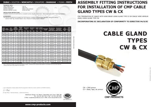
DUBAI • HOUSTON • NEWCASTLE • SINGAPORE • SHANGHAI • PUSAN • PERTHTECHNICAL DATA<strong>CABLE</strong> <strong>GLAND</strong> TYPE: <strong>CW</strong>, <strong>CX</strong>INGRESS PROTECTION: IP66, IP67DESIGN STANDARDS: BS6121:1989, EN50262PROCESS CONTROL SYSTEM : BS EN ISO 9001INSTALLATION INSTRUCTIONSInstallation should only be performed by a competent person using the correct tools. Read all instructions before beginning installation.ACCESSORIESThe following accessories are available from <strong>CMP</strong> <strong>Products</strong>, as optional extras, to assist with fixing, sealing and earthing :-Locknut | Earth Tag | Serrated Washer | Entry Thread (I.P.) Sealing Washer | Shroud *ASSEMBLY FITTING INSTRUCTIONSFOR INSTALLATION OF <strong>CMP</strong> <strong>CABLE</strong><strong>GLAND</strong> <strong>TYPES</strong> <strong>CW</strong> & <strong>CX</strong>FOR TERMINATION OF <strong>CABLE</strong>S WITH WIRE BRAID USING <strong>GLAND</strong> TYPE <strong>CX</strong> OR SINGLE WIRE ARMOUR(SWA) USING <strong>GLAND</strong> TYPE <strong>CW</strong>.INCORPORATING EC DECLARATION OF CONFORMITY TO DIRECTIVE 94/9/ECCableEntryGlandThreadSizeMinThreadLengthCableBeddingDiameterOverallCableDiameter<strong>CW</strong> ArmourRange +<strong>CX</strong> ArmourRange +AcrossFlatsMax Min Max Min Max Min Max Max MaxAcrossCorners ProtrusionLength<strong>CW</strong> OrderingReference(Brass Metric)<strong>CX</strong> OrderingReference(Brass Metric)PVCShroudRef*20S/16 M20 10.0 8.7 6.1 11.5 0.9 1.0 0.0 1.0 24.0 25.9 43.0 20S16<strong>CW</strong>1RA 20S16<strong>CX</strong>1RA PVC04 0.11820S M20 10.0 11.7 9.5 15.9 0.9 1.25 0.0 1.0 24.0 25.9 43.0 20S<strong>CW</strong>1RA 20S<strong>CX</strong>1RA PVC04 0.11820 M20 10.0 14.0 12.5 20.9 0.9 1.25 0.0 1.0 30.5 32.9 50.0 20<strong>CW</strong>1RA 20<strong>CX</strong>1RA PVC06 0.15925S M25 10.0 20.0 14.0 22.0 1.25 1.6 0.0 1.0 36.0 38.9 55.0 25S<strong>CW</strong>1RA 25S<strong>CX</strong>1RA PVC09 0.22825 M25 10.0 20.0 18.2 26.2 1.25 1.6 0.0 1.0 36.0 38.9 55.0 25<strong>CW</strong>1RA 25<strong>CX</strong>1RA PVC09 0.22832 M32 10.0 26.3 23.7 33.9 1.6 2.0 0.0 1.0 46.0 49.7 58.0 32<strong>CW</strong>1RA 32<strong>CX</strong>1RA PVC11 0.36240 M40 15.0 32.2 27.9 40.4 1.6 2.0 0.0 1.0 55.0 59.4 55.0 40<strong>CW</strong>1RA 40<strong>CX</strong>1RA PVC15 0.52050S M50 15.0 38.2 35.2 46.7 2.0 2.5 0.0 1.0 60.0 64.8 56.0 50S<strong>CW</strong>1RA 50S<strong>CX</strong>1RA PVC18 0.57950 M50 15.0 44.1 40.4 53.1 2.0 2.5 0.0 1.0 70.1 75.7 70.0 50<strong>CW</strong>1RA 50<strong>CX</strong>1RA PVC21 0.60163S M63 15.0 50.0 45.6 59.4 2.0 2.5 0.0 1.0 75.0 81.0 70.0 63S<strong>CW</strong>1RA 63S<strong>CX</strong>1RA PVC23 1.05463 M63 15.0 56.0 54.6 65.9 2.0 2.5 0.0 1.0 80.0 86.4 80.0 63<strong>CW</strong>1RA 63<strong>CX</strong>1RA PVC25 1.20075S M75 15.0 62.0 59.0 72.1 2.0 2.5 0.0 1.0 90.0 97.2 81.1 75S<strong>CW</strong>1RA 75S<strong>CX</strong>1RA PVC28 1.77975 M75 15.0 68.0 66.7 78.5 2.5 3.0 0.0 1.0 100.0 108.0 96.0 75<strong>CW</strong>1RA 75<strong>CX</strong>1RA PVC30 2.37090 M90 15.0 8.0. 76.2 90.4 3.0 3.5 0.0 1.6 114.0 123.1 120.0 90<strong>CW</strong>1RA 90<strong>CX</strong>1RA PVC32 3.515100 M100 15.0 91.0 86.1 101.5 3.15 4.0 0.0 1.6 123.0 132.8 140.0 100<strong>CW</strong>1RA 100<strong>CX</strong>1RA 150/50HST 4.100115 M115 15.0 98.0 101.5 110.3 3.15 4.0 0.0 1.6 133.4 144.1 160.0 115<strong>CW</strong>1RA 115<strong>CX</strong>1RA 180/60HST 4.600130 M130 15.0 115.0 114.2 123.3 3.15 4.0 0.0 1.6 146.1 157.8 169.0 130<strong>CW</strong>1RA 130<strong>CX</strong>1RA 180/60HST 5.200Dimensions are displayed in millimetres unless otherwise statedNOTE: *<strong>CMP</strong> SOLO LSF Halogen Free Shrouds also available on request. + Alternative armour clamping range available for non-standard armour sizes. Marine Approvalsincluding Lloyds & ABS are also available from <strong>CMP</strong> <strong>Products</strong>.CableGlandWeight(Kgs)Cable Gland Selection Table<strong>CABLE</strong> <strong>GLAND</strong><strong>TYPES</strong><strong>CW</strong> & <strong>CX</strong><strong>CMP</strong> Document No. FI416 Issue 1 11/10I, the undersigned, hereby declare that the equipment referred to herein conforms to 94/9/EC directive.<strong>CW</strong> = SWA armour<strong>CX</strong> = Braid, Tape, etc armourDr Geof Mood - Technical Director - (Authorised Person)Glasshouse Street • St. Peters • Newcastle upon Tyne • NE6 1BSTel: +44 191 265 7411 • Fax: +44 191 265 0581E-Mail: cmp@cmp-products.co.uk • Web: www.cmp-products.com<strong>CMP</strong> PRODUCTSwww.cmp-products.com
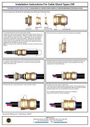
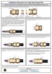
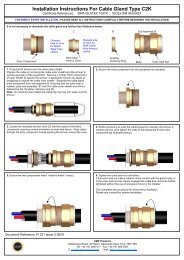
DUBAI • HOUSTON • NEWCASTLE • SINGAPORE • SHANGHAI • PUSAN • PERTHINSTALLATION INSTRUCTIONS FOR <strong>CMP</strong> <strong>CABLE</strong> <strong>GLAND</strong> <strong>TYPES</strong> <strong>CW</strong> & <strong>CX</strong><strong>CABLE</strong> <strong>GLAND</strong> COMPONENTS1. Entry Component2. Detachable Armour Cone3. AnyWay Clamping Ring4. Body5. Outer Seal Nut12345www.cmp-products.com4. While continuing to push the cable forward to maintain contact between the braid armour andthe Cone (2), tighten the Body (4) by hand until the AnyWay Clamping Ring (3) is felt to haveengaged the braid/armour.Hold the Entry Component (1) with a spanner and tighten the Body (4) using a spanner until allavailable threads are used.(A SWA cone is shown in the illustration, but the cable gland will be supplied with the correct cone - steppedtype for <strong>CW</strong> glands and grooved type for <strong>CX</strong> glands.PLEASE READ ALL INSTRUCTIONS CAREFULLY BEFORE BEGINNING THE INSTALLATION1. Separate components (1), (2) and (3) from Sub-Assembly B. If required, fit a shroud over the cableouter sheath. Prepare the cable by removing the cable outer sheath and the braid/armour to suit thegeometry of the equipment.Remove a further 18mm (max) of outer sheath to expose the armour. If applicable remove any tapesor wrappings to expose the inner sheath.NOTE: On maximum size cables the clamping ring may only pass over the armour.5. Ensure the Entry Item (1) and Body (4) are fully tightened togetherSWABRAID2. Secure the Entry Component (1) into the equipment as indicated.6. Tighten the Outer Seal Nut (5) until it comes to an effective stop. This will occur when:-A) The Outer Seal Nut (5) has clearly engaged the cable and cannot be further tightenedwithout the use of excessive force by the installer.B) The Outer Seal Nut (5) is metal to metal with the body of the gland (4).3. Locate the Detachable Armour Cone (2) into the Entry Component. Pass the cable through the entryitem and evenly space the braid/armour around the cone.SWABRAIDwww.cmp-products.comDUBAI • HOUSTON • NEWCASTLE • SINGAPORE • SHANGHAI • PUSAN • PERTH