On the surface topography of ultrashort laser pulse treated steel ...
On the surface topography of ultrashort laser pulse treated steel ...
On the surface topography of ultrashort laser pulse treated steel ...

You also want an ePaper? Increase the reach of your titles
YUMPU automatically turns print PDFs into web optimized ePapers that Google loves.
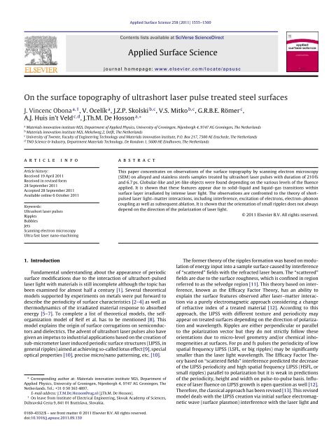
Applied Surface Science 258 (2011) 1555–1560Contents lists available at SciVerse ScienceDirectApplied Surface Sciencej our nal ho me p age: www.elsevier.com/loc ate/apsusc<strong>On</strong> <strong>the</strong> <strong>surface</strong> <strong>topography</strong> <strong>of</strong> <strong>ultrashort</strong> <strong>laser</strong> <strong>pulse</strong> <strong>treated</strong> <strong>steel</strong> <strong>surface</strong>sJ. Vincenc Obona a,1 ,V. Ocelík a , J.Z.P. Skolski b,c , V.S. Mitko b,c , G.R.B.E. Römer c ,A.J. Huis in’t Veld c,d , J.Th.M. De Hosson a,∗a Materials innovation institute M2i, Department <strong>of</strong> Applied Physics, University <strong>of</strong> Groningen, Nijenborgh 4, 9747 AG Groningen, The Ne<strong>the</strong>rlandsb Materials innovation institute M2i, Mekelweg 2, Delft, The Ne<strong>the</strong>rlandsc University <strong>of</strong> Twente, Faculty <strong>of</strong> Engineering Technology and Materials innovation institute, P.O. Box 217, 7500 AE Enschede, The Ne<strong>the</strong>rlandsd TNO Science & Industry, Department Materials Technology, De Rondom 1, 5600 HE Eindhoven, The Ne<strong>the</strong>rlandsa r t i c l e i n f oArticle history:Received 19 April 2011Received in revised form28 September 2011Accepted 28 September 2011Available online 6 October 2011Keywords:Ultrashort <strong>laser</strong> <strong>pulse</strong>sRipplesBubblesJetsScanning electron microscopyUltra fast <strong>laser</strong> nano-machininga b s t r a c tThis paper concentrates on observations <strong>of</strong> <strong>the</strong> <strong>surface</strong> <strong>topography</strong> by scanning electron microscopy(SEM) on alloyed and stainless <strong>steel</strong>s samples <strong>treated</strong> by <strong>ultrashort</strong> <strong>laser</strong> <strong>pulse</strong>s with duration <strong>of</strong> 210 fsand 6.7 ps. Globular-like and jet-like objects were found depending on <strong>the</strong> various levels <strong>of</strong> <strong>the</strong> fluenceapplied. It is shown that <strong>the</strong>se features appear due to solid–liquid and liquid–gas transitions within<strong>surface</strong> layer irradiated by intense <strong>laser</strong> light. The observations are confronted to <strong>the</strong> <strong>the</strong>ory <strong>of</strong> short<strong>pulse</strong>d<strong>laser</strong> light–matter interactions, including interference, excitation <strong>of</strong> electrons, electron–phononcoupling as well as subsequent ablation. It is shown that <strong>the</strong> orientation <strong>of</strong> small ripples does not alwaysdepend on <strong>the</strong> direction <strong>of</strong> <strong>the</strong> polarization <strong>of</strong> <strong>laser</strong> light.© 2011 Elsevier B.V. All rights reserved.1. IntroductionFundamental understanding about <strong>the</strong> appearance <strong>of</strong> periodic<strong>surface</strong> modifications due to <strong>the</strong> interaction <strong>of</strong> <strong>ultrashort</strong>-<strong>pulse</strong>d<strong>laser</strong> light with materials is still incomplete although <strong>the</strong> topic hasbeen examined for almost half a century [1]. Several <strong>the</strong>oreticalmodels supported by experiments on metals were put forward todescribe <strong>the</strong> periodicity <strong>of</strong> <strong>surface</strong> characteristics [2–4] as well as<strong>the</strong>rmodynamics <strong>of</strong> <strong>the</strong> irradiated material response to absorbedenergy [5–7]. To complete a list <strong>of</strong> <strong>the</strong>oretical models, <strong>the</strong> selforganizationmodel <strong>of</strong> Reif et al. has to be mentioned [8]. Thismodel explains <strong>the</strong> origin <strong>of</strong> <strong>surface</strong> corrugations on semiconductorsand dielectrics. The advent <strong>of</strong> <strong>ultrashort</strong> <strong>laser</strong> <strong>pulse</strong>s also havegiven an impetus to industrial applications based on <strong>the</strong> creation <strong>of</strong>sub-micrometer <strong>laser</strong> induced periodic <strong>surface</strong> structures (LIPSS, ingeneral ripples) aimed at achieving so-called lotus effect [9], specialoptical properties [10], precise micro/nano patterning, etc. [10].∗ Corresponding author at: Materials innovation institute M2i, Department <strong>of</strong>Applied Physics, University <strong>of</strong> Groningen, Nijenborgh 4, 9747 AG Groningen, TheNe<strong>the</strong>rlands. Tel.: +31 0 50 363 4897.E-mail address: J.T.M.De.Hosson@rug.nl (J.Th.M. De Hosson).1 <strong>On</strong> leave from Institute <strong>of</strong> Electrical Engineering, Slovak Academy <strong>of</strong> Sciences,Dúbravská Cesta 9, 841 01 Bratislava, Slovakia.The former <strong>the</strong>ory <strong>of</strong> <strong>the</strong> ripples formation was based on modulation<strong>of</strong> energy input into a sample <strong>surface</strong> caused by interference<strong>of</strong> “scattered” fields with <strong>the</strong> refracted <strong>laser</strong> beam. The “scattered”fields are due to <strong>the</strong> <strong>surface</strong> roughness, which is confined in regionreferred to as <strong>the</strong> selvedge region [11]. This <strong>the</strong>ory based on interference,known as <strong>the</strong> Efficacy Factor Theory, has an ability toexplain <strong>the</strong> <strong>surface</strong> features observed after <strong>laser</strong>–matter interactionvia a purely electromagnetic approach considering a change<strong>of</strong> refractive index <strong>of</strong> a <strong>treated</strong> material [12]. According to thisapproach, <strong>the</strong> LIPSS with different texture and periodicity mayappear on <strong>treated</strong> <strong>surface</strong>s depending on <strong>the</strong> direction <strong>of</strong> polarizationand wavelength. Ripples are ei<strong>the</strong>r perpendicular or parallelto <strong>the</strong> polarization vector but <strong>the</strong>y do not strictly follow <strong>the</strong>seorientations due to micro-level geometry and/or chemical inhomogeneitiesat <strong>surface</strong>s. For ps and fs <strong>pulse</strong>s <strong>the</strong> periodicity <strong>of</strong> lowspatial frequency LIPSS (LSFL, or big ripples) may be significantlysmaller than <strong>the</strong> <strong>laser</strong> light wavelength. The Efficacy Factor Theorybased on “scattered fields” interference predicted <strong>the</strong> decrease<strong>of</strong> <strong>the</strong> LIPSS periodicity and high spatial frequency LIPSS (HSFL, orsmall ripples) parallel to polarization but it is weak in predictions<strong>of</strong> <strong>the</strong> periodicity, height and width on <strong>pulse</strong>-to-<strong>pulse</strong> basis. Influence<strong>of</strong> <strong>laser</strong> fluence on LIPSS growth is open question as well [12].Therefore, <strong>the</strong> classical approach has been revised [13]. This revisedmodel deals with <strong>the</strong> LIPSS creation via initial <strong>surface</strong> electromagneticwave (<strong>surface</strong> plasmon) interference with <strong>the</strong> <strong>laser</strong> light and0169-4332/$ – see front matter © 2011 Elsevier B.V. All rights reserved.doi:10.1016/j.apsusc.2011.09.130
1556 J. Vincenc Obona et al. / Applied Surface Science 258 (2011) 1555–1560subsequent grating-assisted <strong>surface</strong> plasmon–<strong>laser</strong> coupling. It canprovide a view <strong>of</strong> LSFL growth [13] on various materials includingmetals, semiconductors and dielectrics for multiple exposures.However, it is still unable to give a full explanation <strong>of</strong> HSFL creation.In this work, we show that <strong>surface</strong> features created by <strong>laser</strong><strong>pulse</strong>s on alloyed and stainless <strong>steel</strong> start at low fluence with smallsphere-like objects (bubbles) followed with increasing fluence byelongated HSFL parallel to <strong>laser</strong> beam polarization vector. At evenhigher fluence <strong>the</strong> coexistence <strong>of</strong> orthogonal system <strong>of</strong> HSFL andLSFL, was observed. Surprisingly, as shown in this paper, HSFLlooses its polarization vector dependency in <strong>the</strong> presence <strong>of</strong> LSFLat high fluences. The HSFL becomes perpendicular to sidewalls <strong>of</strong><strong>the</strong> LSFL. For explanation <strong>of</strong> this phenomenon, effects beyond <strong>the</strong>purely electromagnetic have to be taken into account. Observationspublished in ref. [6] suggest that also relaxation <strong>of</strong> <strong>the</strong> absorbedenergy plays a significant role in <strong>the</strong> <strong>surface</strong> objects creation.The objective <strong>of</strong> this work is to compare two <strong>surface</strong>s <strong>of</strong> <strong>steel</strong>with slightly different chemical compositions. Two <strong>pulse</strong> durations(fs and ps), were used in order to compare influence <strong>of</strong><strong>pulse</strong> duration and electron–phonon relaxation time on <strong>the</strong> <strong>surface</strong><strong>topography</strong>. Detailed inspections by SEM have been made. Crosssections<strong>of</strong> <strong>the</strong> <strong>surface</strong> objects have been prepared by focused ionbeam technique to allow measurement <strong>of</strong> spatial dimensions <strong>of</strong> <strong>the</strong><strong>surface</strong> features.2. ExperimentalIn <strong>the</strong> experiments two different materials as well as <strong>laser</strong> <strong>pulse</strong>generating systems were used.A titanium sapphire based <strong>laser</strong> system (Coherent RegA) witha wavelength <strong>of</strong> 800 nm was applied for machining <strong>of</strong> 800H hightemperature alloy. The <strong>laser</strong> system generates <strong>of</strong> 210 fs <strong>laser</strong> <strong>pulse</strong>swith a Gaussian distribution. The system delivers <strong>the</strong> <strong>pulse</strong>s at afrequency <strong>of</strong> 50 kHz. Average powers <strong>of</strong> 5, 10, 25 and 30 mW wereapplied. The experiment was performed as an exposure in sets <strong>of</strong>parallel lines under various conditions. Laser beam scanning speedwas set to 50, 100, 200, 400 and 800 mm/s. The effect <strong>of</strong> multipleenergy delivery to <strong>the</strong> same <strong>surface</strong> area was realized by applying2, 5, 10 and 20 overscans. Diameter <strong>of</strong> <strong>the</strong> <strong>laser</strong> beam was 20 m.800H <strong>steel</strong> was used as a substrate. Its chemical composition islisted in Table 1. The <strong>surface</strong> was chemically etched prior to <strong>laser</strong>processing to highlight grain boundaries on <strong>the</strong> <strong>surface</strong> [14].An ytterbium-doped YAG (Yb:YAG) system (Triumph TruMicro)with a central wavelength <strong>of</strong> 1030 nm was used for machining <strong>of</strong>stainless AISI 304L <strong>steel</strong>. Its composition is presented in Table 1. The<strong>laser</strong> system generates <strong>laser</strong> <strong>pulse</strong>s (repetition rate 50 kHz) witha maximum <strong>of</strong> 500 mW average power. We used 50 mW powerfor <strong>the</strong> samples treatment. The duration <strong>of</strong> Gaussian shaped <strong>laser</strong><strong>pulse</strong> was 6.7 ps in all experiments. A combination <strong>of</strong> a rotary /2wave plate and a beam splitting cube served as a power attenuator.The <strong>laser</strong> light was linearly polarized. Manipulation <strong>of</strong> <strong>the</strong> beamover <strong>the</strong> sample was accomplished by a two-mirror galvo-scannersystem (Intelliscan 14 <strong>of</strong> ScanLab, Germany). A 100 mm telecentricf-Theta lens (Ronar <strong>of</strong> Linos, Germany) for 1030 nm wavelengthfocused <strong>the</strong> beam to a circular spot with diameter <strong>of</strong> 28 m. Theaverage power was measured at <strong>the</strong> exit <strong>of</strong> <strong>the</strong> scanner system by apower meter. In all experiments <strong>the</strong> normal incidence <strong>of</strong> <strong>laser</strong> lightwas used. The processing conditions used in <strong>the</strong> experiments arelisted in Table 2.Two different microscopy techniques were used to investigate<strong>the</strong> sample <strong>surface</strong>s <strong>treated</strong> by <strong>ultrashort</strong> <strong>laser</strong> <strong>pulse</strong>s. A PhilipsXL30 SEM equipped with a field emission gun <strong>of</strong>fers a lateral resolution<strong>of</strong> <strong>the</strong> <strong>surface</strong> objects at a level <strong>of</strong> few nanometers. The lack<strong>of</strong> height information <strong>of</strong> <strong>the</strong> objects was partially compensated byobservations on tilted <strong>surface</strong>s. The exact pr<strong>of</strong>ile <strong>of</strong> <strong>treated</strong> <strong>surface</strong>Fig. 1. SEM micrograph <strong>of</strong> <strong>the</strong> 800H <strong>steel</strong> sample <strong>treated</strong> by a single 210 fs <strong>laser</strong> <strong>pulse</strong>with <strong>the</strong> 0.1 J <strong>pulse</strong> energy. The sample is tilted vertically in 55 ◦ from normal view.The centre <strong>of</strong> application <strong>of</strong> <strong>laser</strong> beam is located at <strong>the</strong> centre <strong>of</strong> <strong>the</strong> micrograph.RI, B and HSFL area denote random indents, bubbles and area covered by HSFL,respectively.was observed by SEM after cross-sectioning it using focused ionbeam (Tescan Lyra FIB-Field Emission Gun) with Pt depositedprotection.3. ResultsScanning electron microscopy observations <strong>of</strong> <strong>treated</strong> <strong>surface</strong>swere performed on both materials. In order to avoid confusionwhen using <strong>the</strong> term fluence for overlapped and overscanned <strong>laser</strong><strong>pulse</strong>s in <strong>the</strong> following, we mention ra<strong>the</strong>r <strong>the</strong> delivered energy asa combination <strong>of</strong> <strong>pulse</strong> energy, overlap (Eq. (1)) and <strong>the</strong> number<strong>of</strong> overscans instead <strong>of</strong> overall, accumulated or absorbed fluence.Overlap is defined as:O = D − pD × 100% (1)where D is focus spot diameter and p is <strong>the</strong> pitch (<strong>pulse</strong> to <strong>pulse</strong>distance) expressed as scanning speed v, divided by <strong>the</strong> repetitionrate f:p = v fIn <strong>the</strong> case <strong>of</strong> 800H <strong>steel</strong> <strong>treated</strong> by 210 fs <strong>pulse</strong>s, <strong>the</strong> lowestenergy delivered on <strong>the</strong> <strong>surface</strong> was reached by setting <strong>of</strong>0.1 J <strong>pulse</strong> energy and 20% overlap without subsequent overscans.Detailed inspection <strong>of</strong> Fig. 1 reveals predominance <strong>of</strong> randomindents (RI) at <strong>the</strong> margin <strong>of</strong> <strong>the</strong> beam and many bubble-like objects(B) within <strong>the</strong> whole observed area. At <strong>the</strong> highest energy (centre<strong>of</strong> Fig. 1), <strong>the</strong> protrusions started to be organized into aligned linearelongated objects (HSFL).The energy delivered in <strong>the</strong> experiments was increased in threedifferent ways: (i) by increasing <strong>of</strong> <strong>laser</strong> <strong>pulse</strong> energy, (ii) bydecreasing <strong>of</strong> <strong>laser</strong> beam scanning speed at fixed frequency leadingto an increase <strong>of</strong> overlap <strong>of</strong> subsequent <strong>laser</strong> <strong>pulse</strong>s and (iii) by multiplescanning over <strong>the</strong> same <strong>laser</strong> tracks (2, 5, 10 and 20 overscans).The <strong>laser</strong> track presented by SEM pictures in Fig. 2 was obtained byscanning <strong>of</strong> <strong>the</strong> 800H sample <strong>surface</strong> at 0.6 J <strong>pulse</strong> energy and90% overlap. Fig. 2a shows <strong>the</strong> end <strong>of</strong> such <strong>laser</strong> track. The evolution<strong>of</strong> <strong>the</strong> <strong>surface</strong> objects as a function <strong>of</strong> <strong>the</strong> amount <strong>of</strong> energycan be observed in <strong>the</strong> middle <strong>of</strong> this micrograph from <strong>the</strong> rightto <strong>the</strong> left side. Appearance <strong>of</strong> <strong>the</strong> <strong>surface</strong> is continuously changingfrom (i) slightly modified <strong>surface</strong> at <strong>the</strong> right <strong>laser</strong> track marginfollowed by (ii) poorly aligned HSFL (vertically oriented), (iii) wellaligned HSFL and (iv) well aligned HSFL on poorly developed LSFLat <strong>the</strong> area <strong>of</strong> <strong>the</strong> steepest increase <strong>of</strong> <strong>the</strong> delivered energy. Finally,<strong>the</strong> <strong>surface</strong> gets also (v) well-defined LSFL (horizontally oriented)covered by discontinuous HSFL in area with highest energy input.Close-up <strong>of</strong> Fig. 2a displayed on Fig. 2b reveals <strong>the</strong> transition from(2)
J. Vincenc Obona et al. / Applied Surface Science 258 (2011) 1555–1560 1557Table 1Chemical composition <strong>of</strong> 800H and AISI 304L stainless <strong>steel</strong> substrates.C (wt.%) Cr (wt.%) Fe (wt.%) Ni (wt.%) Mn (wt.%) Si (wt.%) P (wt.%) S (wt.%) Al (wt.%) Ti (wt.%) Al/Ti (wt.%)AISI 304L 0.03 18.0–20.0 Bulk 8.0–12.0 2.0 1.0 0.045 0.03 – – –800H 0.06–0.1 19.0–23.0 Bulk 30.0–35.0 – – – – 0.15–0.6 0.15–0.6 0.85–1.2Table 2Summary <strong>of</strong> <strong>the</strong> processing conditions: from left to right: – <strong>laser</strong> light wavelength, – <strong>pulse</strong> duration, ss – spot size, f – repetition rate, P – average <strong>laser</strong> power, E p – <strong>pulse</strong>energy, – incidence angle, v – scanning speed, O – overlap and OS – number <strong>of</strong> overscans. (nm) (fs) ss (m) f (kHz) P (mW) E p (J) ( ◦ ) v (mm/s) O (%) OS800H 800 210 20 50 5–30 0.1–0.6 90 50–800 20–95 2–20304L 1030 6700 28 50 50 10 90 50, 1000 29, 96 5, 50region covered by HSFL (<strong>the</strong> right side) to <strong>the</strong> area <strong>of</strong> coexistence<strong>of</strong> HSFL and LSFL toge<strong>the</strong>r. The rounded-ridge shape <strong>of</strong> <strong>the</strong> HSFL aswell as plenty <strong>of</strong> globular objects on <strong>the</strong> <strong>surface</strong> (Fig. 2b) suggest<strong>the</strong> formation <strong>of</strong> <strong>the</strong> HSFL from <strong>the</strong> liquid state when using 210 fs<strong>laser</strong> <strong>pulse</strong>s.The orientation and spacing <strong>of</strong> HSFL and LSFL were quantifiedusing 2D Fourier transform <strong>of</strong> SEM images (not shown here).Spacing and height <strong>of</strong> <strong>the</strong> <strong>surface</strong> features were investigated oncross-sections prepared with <strong>the</strong> aid <strong>of</strong> FIB technique. Spacing <strong>of</strong>HSFL in <strong>the</strong> areas with low energy delivered is ranging over anaverage distance ∼200–400 nm, and height ∼40–60 nm (Fig. 3a).The LSFL showed an average periodicity <strong>of</strong> ∼650 nm and height <strong>of</strong>200–300 nm (Fig. 3b).The final increase <strong>of</strong> delivered energy in this experiment wasreached by making an overscan <strong>of</strong> already existing <strong>laser</strong> tracks.Fig. 4 shows a wavy <strong>surface</strong> <strong>of</strong> <strong>the</strong> same 800H <strong>steel</strong> sample <strong>treated</strong>with <strong>laser</strong> <strong>pulse</strong> energy 0.6 J, 80% overlap and 10 overscans. Here<strong>the</strong> LSFLs are oriented vertically (<strong>laser</strong> track follows up-downdirection on <strong>the</strong> micrograph, polarization vector is horizontal) andHSFL are again perpendicular to <strong>the</strong>se. The spacing <strong>of</strong> LSFL is comparableto <strong>the</strong> one in Figs. 2 and 3b (∼670 nm). The difference to<strong>the</strong> previous energy level (Fig. 2) lies in a stronger development <strong>of</strong>LSFL with deeper valleys between <strong>the</strong>m. The HSFL bridges <strong>the</strong> LSFL.Again, <strong>the</strong> globular objects are present at <strong>the</strong> <strong>surface</strong> and toge<strong>the</strong>rwith round-ridge shapes <strong>of</strong> HSFL (like frozen liquid) suggest that<strong>the</strong> formation <strong>of</strong> <strong>the</strong> liquid state is <strong>the</strong> last step in process.Ano<strong>the</strong>r experiment with wavelength <strong>of</strong> 1030 nm and <strong>pulse</strong>duration <strong>of</strong> 6.7 ps (see Section 2) shows at high delivered energy(1 J <strong>pulse</strong> energy, 96% overlap and 5 overscans) a slightly differentpicture <strong>of</strong> HSFL and LSFL (Fig. 5). In this case, LSFL (orientedperpendicular to polarization vector) are not continuous butinterrupted quite frequently. The direction <strong>of</strong> HSFL is not anymorecontrolled by <strong>the</strong> orientation <strong>of</strong> <strong>the</strong> polarization vector but<strong>the</strong>y are always located inside valleys between <strong>the</strong> LSFL andoriented perpendicularly to <strong>the</strong>ir sidewalls. Therefore, in someplaces where LSFL are interrupted one may observe HSFL with<strong>the</strong> direction even perpendicular to <strong>the</strong> vector <strong>of</strong> polarization.This observation is <strong>the</strong> clear evidence that a formation <strong>of</strong> HSFLstrongly depends on <strong>the</strong> roughness <strong>of</strong> <strong>treated</strong> <strong>surface</strong>. When LSFLare already present, <strong>the</strong> direction <strong>of</strong> HSFL is not controlled bypolarization direction anymore. The observations suggest that aprocess related to melting <strong>of</strong> <strong>the</strong> material caused by <strong>laser</strong> <strong>pulse</strong>Fig. 2. SEM micrograph <strong>of</strong> <strong>the</strong> 800H <strong>steel</strong> sample <strong>treated</strong> by 210 fs <strong>laser</strong> <strong>pulse</strong>s with 90% overlap and <strong>pulse</strong> energy 0.6 J. (a) Areas with different delivered energies aremarked at <strong>the</strong> end <strong>of</strong> <strong>laser</strong> track. (b) Detail from <strong>the</strong> area with highest delivered energy shows coexistence <strong>of</strong> small and big ripples. Sample was tilted vertically 55 ◦ from <strong>the</strong>normal view.Fig. 3. SEM picture <strong>of</strong> (a) HSFL and (b) LSFL on cross-sections produced by FIB. Process parameters <strong>of</strong> <strong>the</strong> <strong>laser</strong> track preparation are: (a) 0.6 J <strong>pulse</strong> energy, 20% overlapand one scan; (b) 0.6 J, 96% overlap and 20 overscans. Images are tilted 55 ◦ in vertical direction. Pt-IBID and Pt-EBID are protection Pt layers applied by so-called ion beaminduced deposition and electron beam induced deposition, respectively.
1558 J. Vincenc Obona et al. / Applied Surface Science 258 (2011) 1555–15604. DiscussionFig. 4. SEM micrograph <strong>of</strong> <strong>the</strong> 800H <strong>steel</strong> sample <strong>treated</strong> by 210 fs <strong>laser</strong> <strong>pulse</strong>s, 0.6 J<strong>laser</strong> <strong>pulse</strong> energy, 80% overlap and 10 overscans. Periodicity <strong>of</strong> LSFL is indicated.Sample tilted vertically 55 ◦ from normal view.Fig. 5. SEM micrograph <strong>of</strong> <strong>the</strong> 304L <strong>steel</strong> sample <strong>treated</strong> by 6.7 ps <strong>laser</strong> <strong>pulse</strong>s, 1 J<strong>pulse</strong> energy, 96% overlap and 5 overscans. LSFLs have horizontal direction (perpendicularto polarization). Orientation <strong>of</strong> small ripples is perpendicular to <strong>the</strong> sidewalls<strong>of</strong> LSFLs.impingement is most responsible for shape and direction <strong>of</strong> <strong>the</strong>HSFL.Although Figs. 2b, 4 and 5 already indicated traces <strong>of</strong> liquidphase, Fig. 6 shows <strong>the</strong>se features in a more pronounced way. Manydroplets appear on <strong>the</strong> <strong>surface</strong> as well as <strong>the</strong> small resolidifiedjet-like objects (marked by arrows) with spherical top ends.Fig. 6. SEM micrograph <strong>of</strong> <strong>the</strong> 304L <strong>steel</strong> sample <strong>treated</strong> by 6.7 ps <strong>laser</strong> <strong>pulse</strong>s, 1 J<strong>pulse</strong> energy and 29% overlap. The arrows indicate resolidified droplets and smalljet-like objects with spherical ends. Inset <strong>of</strong> <strong>the</strong> micrograph shows details <strong>of</strong> suchfeatures captured at 35 ◦ vertical tilt from normal view.In literature it has been shown that even for <strong>laser</strong> <strong>pulse</strong>s withduration shorter than few picoseconds, solid (s)–liquid (l)–vapor (g)transitions may play significant role in <strong>the</strong> process <strong>of</strong> <strong>the</strong> absorbedenergy relaxation, on irradiated metal <strong>surface</strong>s [15]. In <strong>the</strong> work <strong>of</strong>Korte et al. [16], <strong>the</strong> influence <strong>of</strong> electron–phonon coupling (EPC)was discussed in order to explain <strong>the</strong> different nature <strong>of</strong> materialablation for transition Cr and noble Au metals. They mentionedweak EPC <strong>of</strong> Au to be responsible for strong melt dynamics andsubsequent ablation to occur out <strong>of</strong> <strong>the</strong> molten phase. In <strong>the</strong> case<strong>of</strong> Cr, <strong>the</strong> strong EPC should cause ablation <strong>of</strong> <strong>the</strong> material almostwithout melting.Two kinds <strong>of</strong> high-alloyed stainless <strong>steel</strong>s 800H (Cr 19–23 wt.%,Ni 30–35 wt.%) and AISI 304L (Cr 18–20 wt.%, Ni 8–12 wt.%) widelyused in industrial applications are investigated in this work. Incontradiction to <strong>the</strong> observations in ref. [16], we observed on oursamples a significant appearance <strong>of</strong> liquid phase in <strong>the</strong> form <strong>of</strong> individualspheres and rounded spherical knops on <strong>the</strong> top <strong>of</strong> laterallyelongated features, at very low applied energy. With increasingenergy, <strong>the</strong> liquid phase features lie on <strong>the</strong> <strong>surface</strong> in <strong>the</strong> form <strong>of</strong>HSFL, crossing <strong>the</strong> LSFL, toge<strong>the</strong>r with substantial amount <strong>of</strong> sphericalobjects on <strong>the</strong> <strong>surface</strong>. Finally, for <strong>the</strong> highest applied energy<strong>the</strong>se liquid-like objects in <strong>the</strong> form <strong>of</strong> jets with globular ends fillup <strong>the</strong> grooves between LSFL, again with a substantial amount <strong>of</strong>isolated spherical droplets on <strong>the</strong> <strong>surface</strong>.In order to explain <strong>the</strong> appearance <strong>of</strong> <strong>the</strong> resolidified <strong>surface</strong>objects, we will divide <strong>the</strong> <strong>laser</strong>–matter interaction into <strong>the</strong>se threesubsequent steps, according to <strong>the</strong> time scales and <strong>the</strong> nature <strong>of</strong> <strong>the</strong>processes involved:• Modulation <strong>of</strong> <strong>laser</strong> light absorption described by Efficacy FactorTheory and/or initial <strong>surface</strong> plasmon interference with <strong>the</strong><strong>laser</strong> light followed by grating-assisted <strong>surface</strong> plasmon–<strong>laser</strong>coupling [11–13], and <strong>laser</strong> energy absorption by free electrongas.• Transfer <strong>of</strong> <strong>the</strong> absorbed energy to <strong>the</strong> phonons described bywidely accepted two-temperature model [17].• Response <strong>of</strong> <strong>the</strong> irradiated material to <strong>the</strong> energy transfer [6,7].4.1. Efficacy Factor Theory, <strong>surface</strong> plasmon interference followedby grating-assisted coupling – energy absorptionLaser <strong>pulse</strong> duration, wavelength, beam incidence angle, sample<strong>surface</strong> roughness and refraction index <strong>of</strong> <strong>the</strong> irradiated materialare <strong>the</strong> process parameters that strongly govern <strong>the</strong> <strong>laser</strong> energydeposition in <strong>the</strong>se <strong>the</strong>oretical approaches. Both models are ableto explain <strong>the</strong> origin <strong>of</strong> periodic modification in experiments butfail in particular cases. The objective <strong>of</strong> this paper is not to evaluatein detail which <strong>of</strong> <strong>the</strong> approaches is more appropriate bu<strong>the</strong>re we concentrate on an explanation <strong>of</strong> <strong>the</strong> orientation <strong>of</strong> <strong>the</strong>HSFL with respect to polarization that was found ei<strong>the</strong>r parallel <strong>of</strong>independent at higher applied fluences.As pointed out in ref. [12], it is difficult to predict <strong>the</strong> LIPSS characteristicson a <strong>pulse</strong>-to-<strong>pulse</strong> basis via <strong>the</strong> Efficacy Factor Theorydue to (i) evolution <strong>of</strong> <strong>surface</strong> roughness and simultaneously (ii)poor knowledge <strong>of</strong> changes in <strong>the</strong> refraction index during <strong>the</strong> <strong>laser</strong><strong>pulse</strong>s. In (i), <strong>the</strong> <strong>surface</strong> roughness has a stochastic nature and ischaracterized by spherically shaped islands. This assumption hascertain restrictions for HSFL and LSFL already developed after <strong>the</strong>first couple <strong>of</strong> <strong>pulse</strong>s. However, <strong>the</strong> periodicity can be predictedfor lower roughness. Also <strong>the</strong> orientation parallel to polarizationfor deep-sub-wavelength, so-called dissident (or type-d) structurescan be described [12]. For (ii), <strong>the</strong> lack <strong>of</strong> knowledge <strong>of</strong> changesin <strong>the</strong> refraction index was circumvented by <strong>the</strong> introduction <strong>of</strong>an effective refraction index. These computational results showed
J. Vincenc Obona et al. / Applied Surface Science 258 (2011) 1555–1560 1559that <strong>the</strong> approach has an ability to model periodicities for LSFLsmaller than <strong>the</strong> initial <strong>laser</strong> wavelength and HSFL fringes parallelto polarization, as well. However, quantitative predictions <strong>of</strong>LIPSS periodicity, width and height on a <strong>pulse</strong>-to-<strong>pulse</strong> basis arenot feasible yet [12].Huang et al. [13] used ano<strong>the</strong>r model with excellent ability to fitexperimental results on various materials and to read out dielectricfunction <strong>of</strong> <strong>the</strong> <strong>treated</strong> material. The model deals with a modulation<strong>of</strong> absorbed energy via <strong>the</strong> interaction <strong>of</strong> highly excited <strong>surface</strong>states, <strong>surface</strong> plasmons, with incoming <strong>laser</strong> light. For multiple<strong>pulse</strong>s, so-called grating-assisted coupling is responsible for deepening<strong>of</strong> <strong>the</strong> <strong>surface</strong> ripples and shrinkage <strong>of</strong> <strong>the</strong> ripples periodicity.In fact, although <strong>the</strong> model seems to be very successful in multi<strong>pulse</strong>exposure description, it apparently fails in <strong>the</strong> description<strong>of</strong> few <strong>pulse</strong>s experiment. The model assumes that <strong>the</strong> <strong>surface</strong>plasmon–<strong>laser</strong> interference is responsible for <strong>the</strong> initialization <strong>of</strong>LSFL and <strong>the</strong> transverse magnetic characteristic <strong>of</strong> <strong>surface</strong> plasmondetermines <strong>the</strong> polarization dependence <strong>of</strong> <strong>the</strong> ripples [13]. It isclear that <strong>the</strong> model definitely can not describe <strong>the</strong> creation <strong>of</strong> HSFLparallel to polarization and nothing can be said about polarizationindependent structures at higher fluencies.In general, <strong>the</strong>se two models predict where <strong>the</strong> absorption couldbe expected on <strong>the</strong> sample <strong>surface</strong>. The <strong>laser</strong> energy is absorbedby free electron gas excitations. In a metal <strong>the</strong>y exclusively occurvia inverse Bremsstrahlung and consecutive collisions among electronslead to <strong>the</strong> <strong>the</strong>rmalization within <strong>the</strong> electron gas on a timescale <strong>of</strong> about 100 fs [18].4.2. Transfer <strong>of</strong> absorbed energy to <strong>the</strong> phononsIn <strong>the</strong> previous section, two models <strong>of</strong> modulated energyabsorption are used to describe where <strong>the</strong> delivered energy isabsorbed. However, <strong>the</strong>y do not predict what <strong>the</strong> response <strong>of</strong> <strong>the</strong>irradiated material to this absorbed energy will be.In <strong>the</strong> following step, delayed up to tens <strong>of</strong> picoseconds, <strong>the</strong>transfer <strong>of</strong> energy from overheated electron gas to <strong>the</strong> phononsoccurs. Evolution <strong>of</strong> <strong>the</strong> electron gas and <strong>the</strong> lattice temperatures isdescribed by two-temperature model [17]. Two <strong>of</strong> <strong>the</strong> most importantparameters in <strong>the</strong> model are electron <strong>the</strong>rmal conductivity K eand so-called EPC constant G. The higher <strong>the</strong> electron conductivity<strong>the</strong> lower is <strong>the</strong> peak electron temperature on <strong>the</strong> <strong>surface</strong> due to amore efficient electron <strong>the</strong>rmal diffusion into <strong>the</strong> bulk material (in<strong>the</strong> case <strong>of</strong> noble metals). <strong>On</strong> <strong>the</strong> o<strong>the</strong>r hand, a higher values <strong>of</strong> G andlow values <strong>of</strong> K e (most <strong>of</strong> <strong>the</strong> transition metals and in <strong>the</strong> case <strong>of</strong> Ni,Fe, Cr based <strong>steel</strong>s) lead to a faster equilibrating dynamics between<strong>the</strong> lattice and <strong>the</strong> electron baths towards <strong>the</strong> common equilibriumtemperature. Comparison <strong>of</strong> <strong>the</strong> electron <strong>the</strong>rmal conductivitiesand electron–phonon coupling constants for two typical representatives(Ni, Au) <strong>of</strong> <strong>the</strong> metal groups were chosen from [19]. TheK e,Ni /K e,Au ≈ 0.3 and G Ni /G Au ≈ 18 ratios, respectively, clearly show,that for <strong>the</strong> same applied energies, much faster (violent) transfer<strong>of</strong> <strong>the</strong> much less diffused energy occurs, in <strong>the</strong> case <strong>of</strong> low K e andhigh G metals. It means that for Ni and metals with similar materialconstants much higher <strong>surface</strong> temperatures should be expectedin comparison to noble metals.4.3. Response <strong>of</strong> <strong>the</strong> irradiated materialSo far, we mentioned that it is possible to explain <strong>the</strong> occurrence<strong>of</strong> preferentially absorbed energy according <strong>the</strong> Efficacy Factor Theoryand <strong>surface</strong>-plasmon-interference-model. Here, we will answer<strong>the</strong> following questions:(i) What is <strong>the</strong> nature <strong>of</strong> <strong>the</strong> HSFL growth at low fluences (fewapplied <strong>pulse</strong>s)?Fig. 7. Schematic drawing <strong>of</strong> <strong>laser</strong>–matter interaction shows our hypo<strong>the</strong>sis for<strong>laser</strong> light absorption: (a) for low energy and smooth <strong>surface</strong> from top view as well as(b) for high energy and rough <strong>surface</strong>. HSFL and LSFL mean absorption <strong>of</strong> <strong>the</strong> energyalong HSFL and LSFL directions, respectively. Drawing (c) represents <strong>the</strong> side view<strong>of</strong> expansion <strong>of</strong> high energy irradiated material with part <strong>of</strong> <strong>the</strong> material subjectedto violent solid–gas transition (s–g) in his upper layer and part to melting (s–l) orphase explosions (l–g) in deeper layer.(ii) How can we explain <strong>the</strong> transfer from HSFL to LSFL?(iii) What is <strong>the</strong> nature <strong>of</strong> <strong>the</strong> HSFL growth between <strong>the</strong> LSFL athigher fluences?Current analytical methods do not allow a direct investigation<strong>of</strong> <strong>the</strong> HSFL and LSFL formation by spatial-resolved methods withnanometer resolutions. Moreover, <strong>the</strong> Efficacy Factor Theory hasnot provided a suitable tool to calculate <strong>the</strong> <strong>laser</strong> light absorptionon <strong>pulse</strong>-to-<strong>pulse</strong> basis, up to now. Restriction <strong>of</strong> <strong>surface</strong>-plasmoninterference-modelin description <strong>of</strong> HSFL parallel to polarizationwas mentioned, as well. To describe fully both kinds <strong>of</strong> HSFLs formation,we should consider <strong>the</strong>se four factors: absorption, electron<strong>the</strong>rmal conductivity, electron–phonon coupling and subsequentrelaxation <strong>of</strong> <strong>the</strong> irradiated volume.Exposure <strong>of</strong> <strong>the</strong> sample <strong>surface</strong> with low <strong>pulse</strong> energies at highprocessing speed shown in Fig. 1 can be considered as a single <strong>pulse</strong>impingement. Marginal part <strong>of</strong> <strong>the</strong> spot reveals random deposition<strong>of</strong> energy, while in <strong>the</strong> centre, at slightly higher deposited energy,first HSFL collinear to polarization vector appeared. These can belinked to HSFL type-d structures in ref. [12]. However, in Fig. 2a(right side <strong>of</strong> <strong>the</strong> picture), we can clearly see <strong>the</strong> HSFL type-d structureseven for multi-<strong>pulse</strong> exposures (90% overlapped <strong>laser</strong> spots)on rougher <strong>surface</strong> due to previous <strong>pulse</strong> impingements. Here, <strong>the</strong><strong>laser</strong> light absorption is still collinear to polarization (see Fig. 7a),even thought <strong>the</strong> delivered energy is higher in comparison to Fig. 1.<strong>On</strong> <strong>the</strong> o<strong>the</strong>r hand, in <strong>the</strong> case <strong>of</strong> high delivered energy(Figs. 5 and 6) on rough <strong>surface</strong>s <strong>the</strong>re is a possibility <strong>of</strong> higherenergy absorption (Fig. 7b). We observe <strong>the</strong> presence <strong>of</strong> <strong>the</strong> welldeveloped LSFL (type-s structures in ref. [12]) orthogonal to <strong>the</strong>polarization vector with HSFL almost all lying between sidewalls<strong>of</strong> <strong>the</strong> LSFL. It seems that <strong>the</strong> side walls takeover control <strong>of</strong> <strong>the</strong>HSFL direction because <strong>the</strong> HSFL completely lost dependence on<strong>the</strong> polarization vector (Fig. 5). Moreover, many jet-like objects are
1560 J. Vincenc Obona et al. / Applied Surface Science 258 (2011) 1555–1560present with spherical endings (Fig. 6 – white arrows). It suggeststhat <strong>the</strong> growth <strong>of</strong> HSFL has a different origin in this case. Never<strong>the</strong>less,both HSFL at low energies and HSFL between LSFL, areassociated with a liquid phase formation.Based on Lambert–Beer law <strong>of</strong> radiation absorption in a material<strong>the</strong>re is a different portion <strong>of</strong> energy absorbed by electrongas excitations at different depths under <strong>the</strong> <strong>surface</strong>. This energyis delivered to phonons. Molecular dynamics modeling by Lewisand Perez [7] showed different nature <strong>of</strong> <strong>the</strong> absorbed energyrelaxations for two energy levels equal to 1.2× and 2.8× ablationthreshold energy, respectively. The single-<strong>pulse</strong> simulationsrevealed for 1.2 multiple <strong>of</strong> ablation threshold energy only tworegions, non-ablated and porous (voids filled by gas). However, for2.8 multiple <strong>of</strong> ablation threshold energy <strong>the</strong>y refer to <strong>the</strong> formation<strong>of</strong> much more intricate pr<strong>of</strong>ile including spallation, phase explosion,fragmentation and vaporization, crossing <strong>the</strong> pr<strong>of</strong>ile from bulkto <strong>the</strong> <strong>surface</strong> side. It is worth mentioning that pathways <strong>of</strong> isochoricexpansion in temperature–density diagrams [7], <strong>the</strong> lowerparts <strong>of</strong> <strong>the</strong> irradiated volume follow solid–liquid–vapor transitionsfor both energy levels.In summary, taking into account <strong>the</strong> particular aspects <strong>of</strong><strong>laser</strong>–matter interaction <strong>the</strong> answer to ‘What is <strong>the</strong> nature <strong>of</strong> <strong>the</strong>HSFL growth at low fluences (few applied <strong>pulse</strong>s)?’, is as follows. In<strong>the</strong> case <strong>of</strong> a slightly higher energy than <strong>the</strong> ablation threshold andan initially smooth <strong>surface</strong>, <strong>the</strong> energy absorption on <strong>steel</strong> <strong>surface</strong>soccurs preferentially parallel to polarization vector (Fig. 7a). Theobservation was supported by computational results originated inEfficacy Factor Theory, [12]). Response <strong>of</strong> <strong>the</strong> irradiated volume tosuch a low energy on <strong>the</strong> absorption places are gentle (s)–(l)–(g)transitions, which cause slight melting <strong>of</strong> <strong>the</strong> <strong>surface</strong> (Fig. 3a).For answering <strong>the</strong> second question, ‘How <strong>the</strong> transfer from HSFLto LSFL could be explained?’, multiple-<strong>laser</strong>-<strong>pulse</strong>s energy absorptionon already roughened <strong>surface</strong> (HSFL) has to be taken intoaccount. In this case, <strong>the</strong> Efficacy Factor Theory is still applicablefor <strong>the</strong> initial few <strong>pulse</strong>s. However, only when <strong>the</strong> amplitude <strong>of</strong><strong>the</strong> <strong>surface</strong> wavy ripples is much smaller than <strong>the</strong> wavelength <strong>of</strong><strong>the</strong> <strong>laser</strong> light a mutually orthogonal system <strong>of</strong> ripples is visible.If <strong>the</strong> ripples amplitude becomes comparable to <strong>the</strong> wavelength,<strong>the</strong> ripples transversal to <strong>the</strong> polarization start dominate (Figs. 7band 2a,b). Here, <strong>the</strong> <strong>surface</strong>-plasmon-interference-model, whichpredicts <strong>the</strong> <strong>surface</strong> plasmon propagating only in direction transverseto <strong>the</strong> polarization [13], is more suitable for <strong>the</strong> description<strong>of</strong> our observations. Moreover, our observations <strong>of</strong> LSFL periodicitysmaller than <strong>the</strong> wavelength are in accordance with prediction <strong>of</strong><strong>the</strong> model presented in [13], as well. Previous discussion showedthat both models are needed in <strong>the</strong> description <strong>of</strong> <strong>the</strong> HSFL parallelto polarization and transform from HSFL to LSFL, as well.Finally, we address <strong>the</strong> third (What is <strong>the</strong> nature <strong>of</strong> <strong>the</strong> HSFLgrowth between <strong>the</strong> LSFL at higher fluences?) question. Accordingto <strong>the</strong> <strong>surface</strong>-plasmon-interference-model in combination withgrating-assisted coupling for multiple exposures, one could expectmuch higher energy absorption into progressively deeper ripplegrooves [13]. Following <strong>the</strong> energy transition from electron gas tophonons, an intricate pr<strong>of</strong>ile <strong>of</strong> expanding material is developed(Fig. 3 in [7], Fig. 7c). In <strong>the</strong> lower parts <strong>of</strong> <strong>the</strong> expanding volume <strong>the</strong>absorbed energy relaxes through a process called phase explosion(explosive boiling). The HSFL in this case is formed as common wallsbetween adjacent bursting bubbles. LSFL is <strong>the</strong>n formed duringmultiple <strong>laser</strong> shots as hills between individual expanding events,see Fig. 7c. That is how we can explain independence <strong>of</strong> HSFL onpolarization and <strong>the</strong> direction orthogonal to sidewalls <strong>of</strong> <strong>the</strong> LSFL(see in Fig. 5).5. ConclusionsScanning electron microscopy and focused ion beam facilitieswere used to study <strong>the</strong> <strong>topography</strong> <strong>of</strong> 800H and AlSl 304L <strong>steel</strong><strong>surface</strong>s after its treatment by 210 fs and 6.7 ps <strong>laser</strong> <strong>pulse</strong>s withrepetition rate <strong>of</strong> 50 kHz and <strong>pulse</strong> energy 0.1, 0.2, 0.5, 0.6 and10 J, respectively. Based on current knowledge and our experimentalobservations we concluded that all three processes: (i)modulation <strong>of</strong> absorbed energy and <strong>the</strong> absorption <strong>of</strong> <strong>laser</strong> lightby free electron gas, (ii) diffusion <strong>of</strong> <strong>the</strong> <strong>the</strong>rmalized electrons and(iii) electron–phonon coupling have to be considered as key factorsfor overall explanation <strong>of</strong> <strong>the</strong> LIPSS formation. The conclusions aredetailed as follows:Evolution <strong>of</strong> <strong>the</strong> <strong>surface</strong> objects created by <strong>laser</strong> <strong>pulse</strong>s at low<strong>pulse</strong> energy (∼ablation threshold) starts with <strong>the</strong> formation <strong>of</strong>small spherical objects followed at increasing <strong>pulse</strong> energy wi<strong>the</strong>longated HSFL oriented parallel to polarization vector <strong>of</strong> <strong>laser</strong>beam. They have a characteristic height <strong>of</strong> 30–60 nm with a distancebetween <strong>the</strong>m about 100–250 nm.With increasing energy a mixture <strong>of</strong> HSFL and LSFL, perpendicularto each o<strong>the</strong>r, appears. The LSFL are typically 100–400 nm inheight and <strong>the</strong> distance between <strong>the</strong>m is equal or slightly shorterthan <strong>the</strong> wavelength <strong>of</strong> <strong>the</strong> <strong>laser</strong> light used.At high energy <strong>the</strong> direction <strong>of</strong> HSFL becomes independent on<strong>the</strong> polarization. Simultaneously, HSFL lie at <strong>the</strong> bottom <strong>of</strong> <strong>the</strong> valleysbetween <strong>the</strong> LSFL.AcknowledgementsThis research was carried out under project numberM61.3.08300 in <strong>the</strong> framework <strong>of</strong> <strong>the</strong> Research Program <strong>of</strong><strong>the</strong> Materials innovation institute M2i (www.m2i.nl).References[1] M. Birnbaum, J. Appl. Phys. 36 (1965) 3688–3689.[2] H.M. Van Driel, J.E. Sipe, J.F. Young, Phys. Rev. Lett. 49 (1982) 1955–1958.[3] J. Wang, C. Guo, J. Appl. Phys. 100 (2006) 023511.[4] S. Sakabe, M. Hashida, S. Tokita, S. Namba, K. Okamuro, Phys. Rev. B 79 (2009)033409.[5] S. Nolte, C. Momma, H. Jacobs, A. Tunnermann, B. Chichkov, B. Wellegehausen,H. Welling, J. Opt. Soc. Am. B: Opt. Phys. 14 (1997) 2716–2722.[6] D. von der Linde, K. Sokolowski-Tinten, Appl. Surf. Sci. 154 (2000) 1–10.[7] L.J. Lewis, D. Perez, Appl. Surf. Sci. 255 (2009) 5101–5106.[8] J. Reif, O. Varlamova, S. Varlamov, M. Bestehorn, Appl. Phys. A 104 (2011)969–973.[9] B. Huis in’t Veld, M. Groenendijk, H. Fischer, J. Micro/Nanoeng. 3 (2008)206–210.[10] M. Shinoda, R.R. Gattass, E. Mazur, J. Appl. Phys. 105 (2009) 053102.[11] J.E. Sipe, J.F. Young, J.S. Preston, H.M. Van Driel, Phys. Rev. B 27 (1983)1141–1154.[12] J.Z.P. Skolski, G.R.B.E. Römer, A.J. Huis in‘t Veld, V.S. Mitko, J.V. Obona, V. Ocelik,J.T.M De Hosson, J. Laser Micro/Nanoeng. 5 (2010) 263–268.[13] M. Huang, F. Zhao, Y. Cheng, N. Xu, Z. Xu, ACS Nano 3 (2009) 4062–4070.[14] B. Huis in’t Veld, H. van der Veer, J. Laser Micro/Nanoeng. 5 (2010)28–34.[15] K. Sokolowski-Tinten, J. Bialkowski, A. Cavalleri, D. Von der Linde, A. Oparin, J.Meyer-ter-Vehn, S.I. Anisimov, Phys. Rev. Lett. 81 (1998) 224–227.[16] F. Korte, J. Koch, B.N. Chichkov, Appl. Phys. A 79 (2004) 879–881.[17] S.I. Anisimov, B.L. Kapeliov, T.L. Perel’man, Zh. Eksp. Teor. Fiz. 66 (1974)776–781.[18] D. Breitling, A. Ruf, F. Dausinger, Proc. SPIE 5339 (2004) 49–63.[19] S.S. Wellersh<strong>of</strong>f, J. Hohlfeld, J. Gudde, E. Matthias, Appl. Phys. A: Mater. Sci.Process. 69 (1999) S99–S107.