Flexoelectric rotation of polarization in ferroelectric thin films - Nature
Flexoelectric rotation of polarization in ferroelectric thin films - Nature
Flexoelectric rotation of polarization in ferroelectric thin films - Nature

Create successful ePaper yourself
Turn your PDF publications into a flip-book with our unique Google optimized e-Paper software.
ARTICLES<br />
PUBLISHED ONLINE: 16 OCTOBER 2011 | DOI: 10.1038/NMAT3141<br />
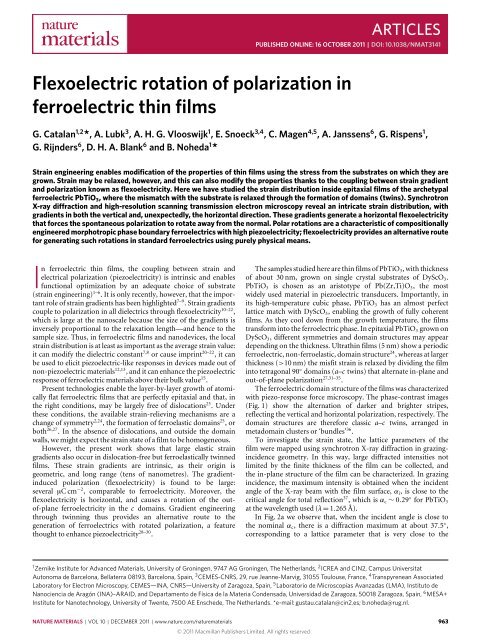
<strong>Flexoelectric</strong> <strong>rotation</strong> <strong>of</strong> <strong>polarization</strong> <strong>in</strong><br />
<strong>ferroelectric</strong> th<strong>in</strong> <strong>films</strong><br />
G. Catalan 1,2 *, A. Lubk 3 , A. H. G. Vlooswijk 1 , E. Snoeck 3,4 , C. Magen 4,5 , A. Janssens 6 , G. Rispens 1 ,<br />
G. Rijnders 6 , D. H. A. Blank 6 and B. Noheda 1 *<br />
Stra<strong>in</strong> eng<strong>in</strong>eer<strong>in</strong>g enables modification <strong>of</strong> the properties <strong>of</strong> th<strong>in</strong> <strong>films</strong> us<strong>in</strong>g the stress from the substrates on which they are<br />
grown. Stra<strong>in</strong> may be relaxed, however, and this can also modify the properties thanks to the coupl<strong>in</strong>g between stra<strong>in</strong> gradient<br />
and <strong>polarization</strong> known as flexoelectricity. Here we have studied the stra<strong>in</strong> distribution <strong>in</strong>side epitaxial <strong>films</strong> <strong>of</strong> the archetypal<br />
<strong>ferroelectric</strong> PbTiO 3 , where the mismatch with the substrate is relaxed through the formation <strong>of</strong> doma<strong>in</strong>s (tw<strong>in</strong>s). Synchrotron<br />
X-ray diffraction and high-resolution scann<strong>in</strong>g transmission electron microscopy reveal an <strong>in</strong>tricate stra<strong>in</strong> distribution, with<br />
gradients <strong>in</strong> both the vertical and, unexpectedly, the horizontal direction. These gradients generate a horizontal flexoelectricity<br />
that forces the spontaneous <strong>polarization</strong> to rotate away from the normal. Polar <strong>rotation</strong>s are a characteristic <strong>of</strong> compositionally<br />
eng<strong>in</strong>eered morphotropic phase boundary <strong>ferroelectric</strong>s with high piezoelectricity; flexoelectricity provides an alternative route<br />
for generat<strong>in</strong>g such <strong>rotation</strong>s <strong>in</strong> standard <strong>ferroelectric</strong>s us<strong>in</strong>g purely physical means.<br />
In <strong>ferroelectric</strong> th<strong>in</strong> <strong>films</strong>, the coupl<strong>in</strong>g between stra<strong>in</strong> and<br />
electrical <strong>polarization</strong> (piezoelectricity) is <strong>in</strong>tr<strong>in</strong>sic and enables<br />
functional optimization by an adequate choice <strong>of</strong> substrate<br />
(stra<strong>in</strong> eng<strong>in</strong>eer<strong>in</strong>g) 1–6 . It is only recently, however, that the important<br />
role <strong>of</strong> stra<strong>in</strong> gradients has been highlighted 7–9 . Stra<strong>in</strong> gradients<br />
couple to <strong>polarization</strong> <strong>in</strong> all dielectrics through flexoelectricity 10–22 ,<br />
which is large at the nanoscale because the size <strong>of</strong> the gradients is<br />
<strong>in</strong>versely proportional to the relaxation length—and hence to the<br />
sample size. Thus, <strong>in</strong> <strong>ferroelectric</strong> <strong>films</strong> and nanodevices, the local<br />
stra<strong>in</strong> distribution is at least as important as the average stra<strong>in</strong> value:<br />
it can modify the dielectric constant 7,8 or cause impr<strong>in</strong>t 20–22 , it can<br />
be used to elicit piezoelectric-like responses <strong>in</strong> devices made out <strong>of</strong><br />
non-piezoelectric materials 12,13 , and it can enhance the piezoelectric<br />
response <strong>of</strong> <strong>ferroelectric</strong> materials above their bulk value 15 .<br />
Present technologies enable the layer-by-layer growth <strong>of</strong> atomically<br />
flat <strong>ferroelectric</strong> <strong>films</strong> that are perfectly epitaxial and that, <strong>in</strong><br />
the right conditions, may be largely free <strong>of</strong> dislocations 23 . Under<br />
these conditions, the available stra<strong>in</strong>-reliev<strong>in</strong>g mechanisms are a<br />
change <strong>of</strong> symmetry 2,24 , the formation <strong>of</strong> ferroelastic doma<strong>in</strong>s 25 , or<br />
both 26,27 . In the absence <strong>of</strong> dislocations, and outside the doma<strong>in</strong><br />
walls, we might expect the stra<strong>in</strong> state <strong>of</strong> a film to be homogeneous.<br />
However, the present work shows that large elastic stra<strong>in</strong><br />
gradients also occur <strong>in</strong> dislocation-free but ferroelastically tw<strong>in</strong>ned<br />
<strong>films</strong>. These stra<strong>in</strong> gradients are <strong>in</strong>tr<strong>in</strong>sic, as their orig<strong>in</strong> is<br />
geometric, and long range (tens <strong>of</strong> nanometres). The gradient<strong>in</strong>duced<br />
<strong>polarization</strong> (flexoelectricity) is found to be large:<br />
several µC cm −2 , comparable to <strong>ferroelectric</strong>ity. Moreover, the<br />
flexoelectricity is horizontal, and causes a <strong>rotation</strong> <strong>of</strong> the out<strong>of</strong>-plane<br />
<strong>ferroelectric</strong>ity <strong>in</strong> the c doma<strong>in</strong>s. Gradient eng<strong>in</strong>eer<strong>in</strong>g<br />
through tw<strong>in</strong>n<strong>in</strong>g thus provides an alternative route to the<br />
generation <strong>of</strong> <strong>ferroelectric</strong>s with rotated <strong>polarization</strong>, a feature<br />
thought to enhance piezoelectricity 28–30 .<br />
The samples studied here are th<strong>in</strong> <strong>films</strong> <strong>of</strong> PbTiO 3 , with thickness<br />
<strong>of</strong> about 30 nm, grown on s<strong>in</strong>gle crystal substrates <strong>of</strong> DyScO 3 .<br />
PbTiO 3 is chosen as an aristotype <strong>of</strong> Pb(Zr,Ti)O 3 , the most<br />
widely used material <strong>in</strong> piezoelectric transducers. Importantly, <strong>in</strong><br />
its high-temperature cubic phase, PbTiO 3 has an almost perfect<br />
lattice match with DyScO 3 , enabl<strong>in</strong>g the growth <strong>of</strong> fully coherent<br />
<strong>films</strong>. As they cool down from the growth temperature, the <strong>films</strong><br />
transform <strong>in</strong>to the <strong>ferroelectric</strong> phase. In epitaxial PbTiO 3 grown on<br />
DyScO 3 , different symmetries and doma<strong>in</strong> structures may appear<br />
depend<strong>in</strong>g on the thickness. Ultrath<strong>in</strong> <strong>films</strong> (5 nm) show a periodic<br />
<strong>ferroelectric</strong>, non-ferroelastic, doma<strong>in</strong> structure 24 , whereas at larger<br />
thickness (>10 nm) the misfit stra<strong>in</strong> is relaxed by divid<strong>in</strong>g the film<br />
<strong>in</strong>to tetragonal 90 ◦ doma<strong>in</strong>s (a–c tw<strong>in</strong>s) that alternate <strong>in</strong>-plane and<br />
out-<strong>of</strong>-plane <strong>polarization</strong> 27,31–35 .<br />
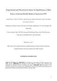
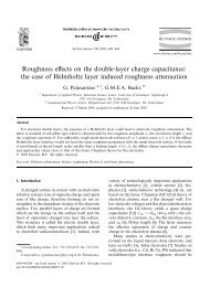
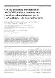
The <strong>ferroelectric</strong> doma<strong>in</strong> structure <strong>of</strong> the <strong>films</strong> was characterized<br />
with piezo-response force microscopy. The phase-contrast images<br />
(Fig. 1) show the alternation <strong>of</strong> darker and brighter stripes,<br />
reflect<strong>in</strong>g the vertical and horizontal <strong>polarization</strong>, respectively. The<br />
doma<strong>in</strong> structures are therefore classic a–c tw<strong>in</strong>s, arranged <strong>in</strong><br />
metadoma<strong>in</strong> clusters or ‘bundles’ 36 .<br />
To <strong>in</strong>vestigate the stra<strong>in</strong> state, the lattice parameters <strong>of</strong> the<br />
film were mapped us<strong>in</strong>g synchrotron X-ray diffraction <strong>in</strong> graz<strong>in</strong>g<strong>in</strong>cidence<br />
geometry. In this way, large diffracted <strong>in</strong>tensities not<br />
limited by the f<strong>in</strong>ite thickness <strong>of</strong> the film can be collected, and<br />
the <strong>in</strong>-plane structure <strong>of</strong> the film can be characterized. In graz<strong>in</strong>g<br />
<strong>in</strong>cidence, the maximum <strong>in</strong>tensity is obta<strong>in</strong>ed when the <strong>in</strong>cident<br />
angle <strong>of</strong> the X-ray beam with the film surface, α i , is close to the<br />
critical angle for total reflection 37 , which is α c ∼ 0.29 ◦ for PbTiO 3<br />
at the wavelength used (λ = 1.265 Å).<br />
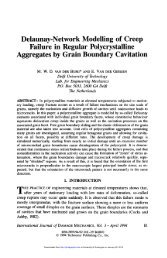
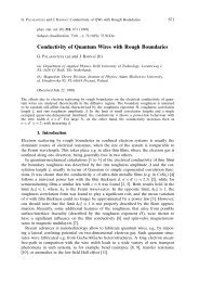
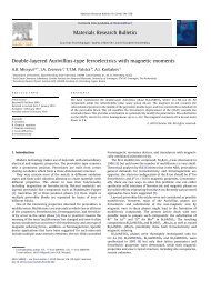
In Fig. 2a we observe that, when the <strong>in</strong>cident angle is close to<br />
the nom<strong>in</strong>al α c , there is a diffraction maximum at about 37.5 ◦ ,<br />
correspond<strong>in</strong>g to a lattice parameter that is very close to the<br />
1 Zernike Institute for Advanced Materials, University <strong>of</strong> Gron<strong>in</strong>gen, 9747 AG Gron<strong>in</strong>gen, The Netherlands, 2 ICREA and CIN2, Campus Universitat<br />
Autonoma de Barcelona, Bellaterra 08193, Barcelona, Spa<strong>in</strong>, 3 CEMES-CNRS, 29, rue Jeanne-Marvig, 31055 Toulouse, France, 4 Transpyrenean Associated<br />
Laboratory for Electron Microscopy, CEMES—INA, CNRS—University <strong>of</strong> Zaragoza, Spa<strong>in</strong>, 5 Laboratorio de Microscopías Avanzadas (LMA), Instituto de<br />
Nanociencia de Aragón (INA)–ARAID, and Departamento de Física de la Materia Condensada, Universidad de Zaragoza, 50018 Zaragoza, Spa<strong>in</strong>, 6 MESA+<br />
Institute for Nanotechnology, University <strong>of</strong> Twente, 7500 AE Enschede, The Netherlands. *e-mail: gustau.catalan@c<strong>in</strong>2.es; b.noheda@rug.nl.<br />
NATURE MATERIALS | VOL 10 | DECEMBER 2011 | www.nature.com/naturematerials 963<br />
© 2011 Macmillan Publishers Limited. All rights reserved
ARTICLES<br />
NATURE MATERIALS DOI: 10.1038/NMAT3141<br />
substrate’s. This broad maximum corresponds to the c doma<strong>in</strong>s,<br />
which have <strong>polarization</strong> out <strong>of</strong> plane and thus a compressed<br />
<strong>in</strong>-plane lattice parameter. As α i <strong>in</strong>creases, a second peak appears<br />
at smaller angles (larger lattice parameters), correspond<strong>in</strong>g<br />
to the a doma<strong>in</strong>s, which have <strong>polarization</strong> <strong>in</strong> plane and<br />
thus horizontal elongation. As the <strong>in</strong>cident angle is further <strong>in</strong>creased,<br />
the two diffraction maxima migrate away from each other,<br />
signall<strong>in</strong>g a grow<strong>in</strong>g difference between the <strong>in</strong>-plane a and c<br />
lattice parameters.<br />
Given that <strong>in</strong>creas<strong>in</strong>g the <strong>in</strong>cidence angle <strong>in</strong>creases the penetration<br />
depth <strong>of</strong> the X-rays 37 , it is tempt<strong>in</strong>g to assign the <strong>in</strong>creased<br />
tetragonality to lattice planes that are deeper 38 . However, it makes<br />
little physical sense that the least cubic parts <strong>of</strong> the film should be<br />
those closest to the substrate. Moreover, all the change <strong>in</strong> our <strong>films</strong><br />
happens at angles above the critical <strong>in</strong>cidence one, for which the<br />
X-ray penetration depth is already larger than the entire thickness <strong>of</strong><br />
the film (as confirmed by the observation <strong>of</strong> the substrate peak). The<br />
observed evolution <strong>of</strong> the diffraction maxima with <strong>in</strong>cidence angle<br />
reflects <strong>in</strong>stead a distribution <strong>of</strong> crystallographic <strong>in</strong>cl<strong>in</strong>ation angles<br />
with<strong>in</strong> the doma<strong>in</strong>s. In bulk tetragonal tw<strong>in</strong>n<strong>in</strong>g, the Bragg planes<br />
<strong>of</strong> adjacent a and c doma<strong>in</strong>s form an angle (Fig. 2b) that is given by<br />
γ = 2arctan(c/a)−90 ◦ (1)<br />
Figure 1 | Piezo-response force microscopy image <strong>of</strong> a tw<strong>in</strong>ned<br />
<strong>ferroelectric</strong> film. The alternat<strong>in</strong>g dark and pale orange stripes correspond<br />
to narrow doma<strong>in</strong>s with <strong>polarization</strong> alternat<strong>in</strong>g between, respectively, the<br />
vertical and horizontal <strong>polarization</strong>s <strong>in</strong> a 30-nm-thick film <strong>of</strong> PbTiO 3 grown<br />
on SrRuO 3 -buffered DyScO 3 . The image area is 2 µm×2 µm.<br />
This relative angle should be 3.6 ◦ for a fully relaxed PbTiO 3 ,<br />
but <strong>in</strong> the <strong>films</strong> the tetragonality c/a is <strong>in</strong>homogeneous (as<br />
<strong>in</strong>dicated by the X-rays), result<strong>in</strong>g <strong>in</strong> a distribution <strong>of</strong> Bragg-plane<br />
<strong>in</strong>cl<strong>in</strong>ations. The regions with different local <strong>in</strong>cl<strong>in</strong>ations meet the<br />
Bragg condition at different <strong>in</strong>cidence angles (α), and thus the<br />
diffraction data reveal the correlated distribution <strong>of</strong> tetragonality<br />
a<br />
ω (°) ω (°) ω (°) ω (°) ω (°) ω (°)<br />
19<br />
18<br />
17<br />
19<br />
18<br />
17<br />
19<br />
18<br />
17<br />
19<br />
18<br />
17<br />
19<br />
18<br />
17<br />
19<br />
α<br />
i =<br />
0.2°<br />
0.29°<br />
0.35°<br />
0.5°<br />
0.6°<br />
λ = 1.26515 Å<br />
18<br />
0.7°<br />
17<br />
35 36 37 38 39<br />
2θ (°)<br />
b<br />
c<br />
00L (r.l.u.)<br />
2.1<br />
2.0<br />
1.9<br />
γ<br />
a doma<strong>in</strong><br />
α<br />
a<br />
c doma<strong>in</strong><br />
Incident<br />
beam<br />
c<br />
i<br />
002<br />
1.8<br />
¬0.15 ¬0.10 ¬0.05 0 0.05 0.10 0.15<br />
H00 (r.l.u.)<br />
α<br />
Figure 2 | X-ray diffraction data reveal<strong>in</strong>g a correlated distribution <strong>of</strong> tetragonality and tw<strong>in</strong> angles. a, Reciprocal-space maps as a function <strong>of</strong> graz<strong>in</strong>g<br />
<strong>in</strong>cidence angle; b, schematic representation <strong>of</strong> fully relaxed tetragonal doma<strong>in</strong>s, show<strong>in</strong>g the relative Bragg-plane <strong>in</strong>cl<strong>in</strong>ation. Notice that the real<br />
<strong>in</strong>cidence angle for the a doma<strong>in</strong>s, α, is different from the nom<strong>in</strong>al one (α i ) ow<strong>in</strong>g to the tetragonal <strong>in</strong>cl<strong>in</strong>ation angle, γ : that is, α = α i −γ , with γ be<strong>in</strong>g<br />
largest <strong>in</strong> the very th<strong>in</strong> a doma<strong>in</strong>s. c, Reciprocal-space map around the (002) reflection, where the <strong>in</strong>tensity outside the 00L vertical is due to the<br />
distribution <strong>of</strong> crystallographic <strong>in</strong>cl<strong>in</strong>ation with<strong>in</strong> the a doma<strong>in</strong>s (L > 2) as well as the c doma<strong>in</strong>s (L < 1.95) with respect to the substrate planes (L ≡ 2).<br />
964 NATURE MATERIALS | VOL 10 | DECEMBER 2011 | www.nature.com/naturematerials<br />
© 2011 Macmillan Publishers Limited. All rights reserved
NATURE MATERIALS DOI: 10.1038/NMAT3141<br />
ARTICLES<br />
a b c<br />
a doma<strong>in</strong><br />
c doma<strong>in</strong><br />
PbTiO 3<br />
c doma<strong>in</strong><br />
a doma<strong>in</strong><br />
0.6°<br />
0.9°<br />
0.7°<br />
0.7°<br />
0.5°<br />
0.15°<br />
0.4° 0.8°<br />
1°<br />
0.95°<br />
0.3°<br />
0.6°<br />
0.08<br />
0.09<br />
0.09<br />
0.07<br />
0.06<br />
0.055<br />
0.7<br />
0.065<br />
0.045<br />
0.035<br />
0.065<br />
¬0.015<br />
SrRuO 3<br />
20 nm DyScO 3<br />
0.0° (ref.) 20 nm 0.0 (ref.) 20 nm<br />
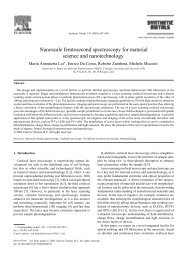
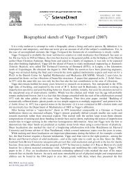
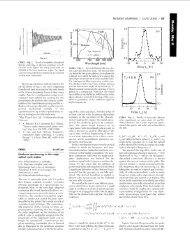
Figure 3 | Direct imag<strong>in</strong>g <strong>of</strong> stra<strong>in</strong> gradients. HAADF-STEM and GPA <strong>of</strong> the PbTiO 3 th<strong>in</strong> film grown on a SrRuO 3 buffer layer deposited on a DyScO 3<br />
substrate and studied <strong>in</strong> cross-section. a, HAADF image, show<strong>in</strong>g the structure. b, The map <strong>of</strong> lattice <strong>rotation</strong>s shows that the upper layers are more<br />
relaxed, and therefore more <strong>in</strong>cl<strong>in</strong>ed, than those close to the <strong>in</strong>terface. c, The out-<strong>of</strong>-plane stra<strong>in</strong> ε zz (relative to the DyScO 3 substrate, c = 3.95 Å) shows a<br />
higher tetragonality <strong>in</strong> the right-hand side <strong>of</strong> the c-doma<strong>in</strong> than <strong>in</strong> the left-hand side (obtuse). The difference arises from the local stress concentrations<br />
required to ‘flatten’ the <strong>in</strong>terface <strong>of</strong> the ferroelastic film onto the substrate, as shown <strong>in</strong> Fig. 5.<br />
and tw<strong>in</strong>n<strong>in</strong>g angle, <strong>in</strong> agreement with equation (1). This can also<br />
be observed <strong>in</strong> the out-<strong>of</strong>-plane diffraction maps around the 00L<br />
reflections (Fig. 2c).<br />
Further <strong>in</strong>sight can be ga<strong>in</strong>ed by probe-corrected high-angle<br />
annular dark-field scann<strong>in</strong>g transmission electron microscopy<br />
(HAADF-STEM) imag<strong>in</strong>g 39,40 , shown <strong>in</strong> Fig. 3. Quantitative<br />
analysis <strong>of</strong> the high-resolution HAADF-STEM images us<strong>in</strong>g<br />
geometric phase analysis (GPA; refs 41,42) and us<strong>in</strong>g the DyScO 3<br />
substrate as reference shows that there is a vertical gradient <strong>of</strong><br />
<strong>in</strong>cl<strong>in</strong>ations between the flatter bottom <strong>in</strong>terface and the more<br />
rumpled free surface, reflect<strong>in</strong>g the grow<strong>in</strong>g distance to the<br />
<strong>in</strong>terface, which is the source <strong>of</strong> stress. More unexpectedly, however,<br />
the <strong>films</strong> also show horizontal stra<strong>in</strong> gradients. The c doma<strong>in</strong>s,<br />
for example, reveal an <strong>in</strong>creased out-<strong>of</strong>-plane elongation <strong>in</strong> the<br />
acute wall–<strong>in</strong>terface corners, and a reduced tetragonality <strong>in</strong> the<br />
obtuse ones.<br />
This dist<strong>in</strong>ctive pattern can be understood by consideration <strong>of</strong><br />
the deformations that are required to attach a film with ferroelastic<br />
doma<strong>in</strong>s onto the flat surface <strong>of</strong> the substrate, as depicted <strong>in</strong> Fig. 4a.<br />
A useful analogy is to imag<strong>in</strong>e the forces needed to flatten an<br />
open book onto a photocopier. The concentration <strong>of</strong> stress at the<br />
corners <strong>of</strong> the doma<strong>in</strong>s leads to locally enhanced deformations,<br />
<strong>in</strong>clud<strong>in</strong>g bend<strong>in</strong>g <strong>of</strong> the doma<strong>in</strong> walls to preserve coherence, as<br />
observed. Yet another way to understand the stra<strong>in</strong> difference is to<br />
consider that, whereas the bottom <strong>in</strong>terface must be flat, the top<br />
<strong>in</strong>terface is freer to relax towards its natural ‘rumpled’ state with<br />
<strong>in</strong>cl<strong>in</strong>ed planes: the net result is that, for each doma<strong>in</strong>, one side is<br />
thicker than the other (see Fig. 4b), and thus there is a horizontal<br />
gradient <strong>of</strong> vertical expansion. This transverse gradient will generate<br />
a horizontal flexoelectricity, caus<strong>in</strong>g the vertical <strong>polarization</strong> to<br />
rotate towards the thicker side (Fig. 4b.)<br />
We can estimate the horizontal flexoelectricity and its effect<br />
on the spontaneous <strong>polarization</strong>. The transverse flexoelectric<br />
coefficient <strong>of</strong> lead zirconate–titanate (PZT) is f 13 ∼ 1 µC m −1<br />
(ref. 43). <strong>Flexoelectric</strong>ity is proportional to permittivity 7,10,12,17 ,<br />
which is ∼5 times smaller for pure PbTiO 3 than for PZT 44 , so the<br />
transverse flexoelectric coefficient <strong>of</strong> PbTiO 3 should be less than<br />
f 13 ≈ 200 nC m −1 . The out-<strong>of</strong>-plane stra<strong>in</strong> difference between the<br />
acute and obtuse corners <strong>of</strong> the c doma<strong>in</strong>s is ε 3 ≈ 0.03 (Fig. 3c),<br />
and the relaxation length is approximately the c-doma<strong>in</strong> width (w ≈<br />
40 nm). Therefore, the average horizontal flexoelectricity across the<br />
doma<strong>in</strong> should be around P x(flexo)<br />
∼ =f13 (ε 3 /w)≈15 µC cm −2 .<br />
This flexoelectric <strong>polarization</strong> is very large; it is <strong>in</strong> fact comparable<br />
to the spontaneous <strong>polarization</strong> <strong>of</strong> archetypal <strong>ferroelectric</strong>s,<br />
and will therefore have a strong effect on the <strong>ferroelectric</strong>ity. In<br />
b<br />
a<br />
a<br />
P ferro<br />
c<br />
Substrate<br />
P flexo<br />
Substrate<br />
Figure 4 | Sketch <strong>of</strong> stresses, stra<strong>in</strong> gradients and polar vectors <strong>in</strong> the<br />
tw<strong>in</strong>ned film. a, Schematic representation <strong>of</strong> the doma<strong>in</strong> structure <strong>in</strong> a film<br />
with a–c doma<strong>in</strong>s. The black arrows represent the stresses that must be<br />
applied to the tw<strong>in</strong>ned film to flatten it onto the substrate. b, The<br />
flexoelectric <strong>polarization</strong> (grey) <strong>in</strong>duces a <strong>rotation</strong> <strong>of</strong> the <strong>ferroelectric</strong><br />
<strong>polarization</strong> <strong>of</strong> the c doma<strong>in</strong> (blue).<br />
particular, the addition <strong>of</strong> the horizontal flexoelectricity to the<br />
vertical <strong>ferroelectric</strong>ity <strong>of</strong> the c doma<strong>in</strong>s will result <strong>in</strong> a rotated<br />
<strong>polarization</strong> (see Fig. 4b), with an angle, β, given by tan β =<br />
P flexo /P ferro . Us<strong>in</strong>g P flexo ∼ 15 µC cm −2 and P ferro = 40–60 µC cm −2 ,<br />
an average polar <strong>rotation</strong> <strong>of</strong> β ∼ 10 ◦ –15 ◦ is expected with respect to<br />
the normal direction.<br />
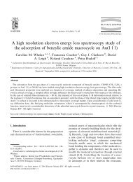
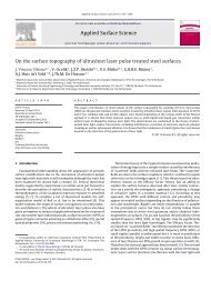
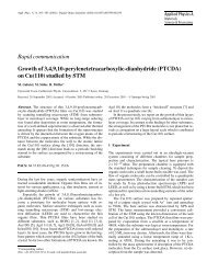
To test this prediction, accurate measurements <strong>of</strong> lattice<br />
distortions were carried out by <strong>in</strong>creas<strong>in</strong>g the STEM resolution<br />
and carry<strong>in</strong>g out dedicated model-based peak f<strong>in</strong>d<strong>in</strong>g to determ<strong>in</strong>e<br />
atomic column positions. Ow<strong>in</strong>g to the Z-dependent contrast,<br />
Pb and TiO columns can be easily dist<strong>in</strong>guished, whereas weakly<br />
scatter<strong>in</strong>g O columns are not visible (see Fig. 5a). On the basis<br />
<strong>of</strong> the determ<strong>in</strong>ed Pb and TiO column positions, both the stra<strong>in</strong><br />
tensor and the Pb–TiO distance vector (proportional to the<br />
electric <strong>polarization</strong> through the Born effective charge tensor 45 )<br />
are mapped unit-cell-wise (see Fig. 5b). Polarization mapp<strong>in</strong>g can<br />
also be done by other electron microscopy techniques 46 , although<br />
HAADF has the advantage that the samples need not be so th<strong>in</strong><br />
and the less aggressive sample preparation helps preserve the<br />
native doma<strong>in</strong> structure 40 .<br />
In agreement with the GPA shown <strong>in</strong> Fig. 3, we observe a<br />
large difference <strong>in</strong> out-<strong>of</strong>-plane stra<strong>in</strong>, tensile <strong>in</strong> the acute corners<br />
and compressive <strong>in</strong> the obtuse ones, lead<strong>in</strong>g to a horizontal<br />
a<br />
NATURE MATERIALS | VOL 10 | DECEMBER 2011 | www.nature.com/naturematerials 965<br />
© 2011 Macmillan Publishers Limited. All rights reserved
ARTICLES<br />
NATURE MATERIALS DOI: 10.1038/NMAT3141<br />
a<br />
I<br />
II<br />
I<br />
II<br />
Pb<br />
Ti<br />
y<br />
b<br />
x<br />
PbTiO 3<br />
DyScO 3<br />
2 nm<br />
Angle <strong>of</strong> <strong>polarization</strong> (°)<br />
90<br />
60<br />
30<br />
c<br />
a<br />
c<br />
0<br />
0 5 10 15<br />
x (nm)<br />
Figure 5 | Direct observation <strong>of</strong> <strong>polarization</strong> <strong>rotation</strong>s. a, HAADF-STEM image with zoom-<strong>in</strong>s show<strong>in</strong>g the a-doma<strong>in</strong> (I) and c-doma<strong>in</strong> (II) atomic column<br />
arrangements with the TiO column shifted <strong>of</strong>f-centre along the direction <strong>of</strong> <strong>polarization</strong>. b, Out-<strong>of</strong>-plane stra<strong>in</strong> (colour map) and electric <strong>polarization</strong><br />
(vector map). The map confirms the stra<strong>in</strong> difference between acute and obtuse corners and reveals the existence <strong>of</strong> polar <strong>rotation</strong>s <strong>in</strong> the c doma<strong>in</strong>s,<br />
which are quantified <strong>in</strong> the l<strong>in</strong>e scan; the <strong>rotation</strong> angle away from the normal is greater than 10 ◦ throughout the entire doma<strong>in</strong>, <strong>in</strong> good agreement with<br />
the calculations.<br />
gradient. Furthermore, a strong <strong>rotation</strong> <strong>of</strong> the electric <strong>polarization</strong><br />
(much greater than the Bragg-plane <strong>in</strong>cl<strong>in</strong>ation) is observed <strong>in</strong> the<br />
c doma<strong>in</strong> (see vectorial map and l<strong>in</strong>escan <strong>in</strong> Fig. 5b). Inspection <strong>of</strong><br />
Fig. 5b confirms a polar <strong>rotation</strong> <strong>of</strong> the order <strong>of</strong> 10 ◦ <strong>in</strong> the middle<br />
<strong>of</strong> the c-doma<strong>in</strong>, <strong>in</strong> agreement with our model. The <strong>rotation</strong> is<br />
even greater near its corners, where the gradient is strongest, and<br />
also near the <strong>in</strong>terface, where the vertical <strong>polarization</strong> is reduced 46 .<br />
We notice also that there is no significant polar <strong>rotation</strong> <strong>in</strong> the<br />
a doma<strong>in</strong>s, also <strong>in</strong> agreement with our model: <strong>in</strong> the a doma<strong>in</strong>s<br />
the <strong>polarization</strong> is already horizontal, so the addition <strong>of</strong> horizontal<br />
flexoelectricity can change its magnitude but not its angle.<br />
The observed <strong>rotation</strong> <strong>of</strong> the <strong>polarization</strong> vector implies that<br />
the <strong>in</strong>ternal symmetry <strong>of</strong> the unit cells is lower than tetragonal,<br />
even though the X-rays do not <strong>in</strong>dicate any monocl<strong>in</strong>ic distortion<br />
<strong>of</strong> the unit cell. This may be due to the small coherence length<br />
<strong>of</strong> the distorted unit cells, or else it might <strong>in</strong>dicate that the unit<br />
cells rema<strong>in</strong> ‘metrically tetragonal’ <strong>in</strong> spite <strong>of</strong> their lower <strong>in</strong>ternal<br />
symmetry. Decoupl<strong>in</strong>g between tetragonality and <strong>polarization</strong> is a<br />
known feature <strong>of</strong> epitaxial th<strong>in</strong> <strong>films</strong>, which rema<strong>in</strong> tetragonal even<br />
when the <strong>polarization</strong> is suppressed 46,47 .<br />
Symmetry lower<strong>in</strong>g through polar <strong>rotation</strong> is thought to be a<br />
cause for the giant piezoelectricity <strong>of</strong> PZT and other <strong>ferroelectric</strong>s<br />
compositionally eng<strong>in</strong>eered to be near a morphotropic phase<br />
boundary 28–30 . Nanodoma<strong>in</strong> formation is <strong>in</strong> fact <strong>in</strong>tr<strong>in</strong>sic near<br />
such boundaries 48 , so it is quite possible that controversies<br />
regard<strong>in</strong>g their symmetry 48–50 are related to the existence <strong>of</strong> <strong>in</strong>ternal<br />
flexoelectricity, seen also <strong>in</strong> relaxors 51 .<br />
<strong>Flexoelectric</strong>ity thus <strong>of</strong>fers a way to <strong>in</strong>duce polar <strong>rotation</strong>s<br />
<strong>in</strong> non-morphotropic <strong>ferroelectric</strong>s us<strong>in</strong>g purely physical means.<br />
The size <strong>of</strong> the gradients is <strong>in</strong>versely proportional to the doma<strong>in</strong><br />
size, which can be tuned by chang<strong>in</strong>g the film thickness or the<br />
film–substrate comb<strong>in</strong>ation 31,32 , and a focused ion beam may<br />
then be used to isolate clusters <strong>of</strong> doma<strong>in</strong>s and measure their<br />
piezoelectric response 52 . Moreover, flexoelectric coefficients are<br />
thought to be larger for lead-free <strong>ferroelectric</strong>s than for leadconta<strong>in</strong><strong>in</strong>g<br />
ones 12 , which has positive implications <strong>in</strong> the quest for<br />
large lead-free piezoelectricity.<br />
Methods<br />
The th<strong>in</strong> <strong>films</strong> have been deposited by pulsed laser deposition, us<strong>in</strong>g a Lambda<br />
Physik COMPex Pro 205 KrF (λ = 248 nm) excimer ultraviolet laser and a<br />
Twente Solid State Technology reflection high-energy electron diffraction vacuum<br />
system. The background pressure was 10 −8 mbar. The PbTiO 3 targets were 2–8%<br />
Pb-enriched s<strong>in</strong>tered ceramics. The target–substrate distance was 48 mm. The<br />
growth took place at a substrate temperature <strong>of</strong> 570 ◦ C, with a laser energy density <strong>of</strong><br />
2 J cm −2 , a laser repetition rate <strong>of</strong> 1 Hz and under an oxygen pressure <strong>of</strong> 0.13 mbar.<br />
The laser spot size on the target was 0.76 mm 2 . The substrates were predeposition<br />
treated to ensure a s<strong>in</strong>gle substrate term<strong>in</strong>ation 53 , and a SrRuO 3 layer was added<br />
as a buffer to aid growth and as an electrode to facilitate functional measurements<br />
with piezoresponse force microscopy. The SrRuO 3 layers had thicknesses rang<strong>in</strong>g<br />
from 5 to 15 nm and were epitaxial with the substrate. The <strong>films</strong> were characterized<br />
us<strong>in</strong>g atomic force microscopy (AFM), piezoresponse AFM, graz<strong>in</strong>g-<strong>in</strong>cidence<br />
X-ray diffraction and STEM. The AFM measurements were made on Agilent 5100<br />
and 5500 AFM systems. For our X-ray diffraction measurements we used both the<br />
facilities <strong>of</strong> the HASYLAB W1 beaml<strong>in</strong>e (DESY, Hamburg) and a Panalytical X’Pert<br />
MRD Cradle (four axes) laboratory diffractometer. Our laboratory diffractometer<br />
is equipped with a copper X-ray generator tube, supply<strong>in</strong>g X-rays with λ = 1.5406 Å<br />
(Cu Kα). The photon energy used at the W1 beaml<strong>in</strong>e is 9,800 eV, correspond<strong>in</strong>g<br />
to a wavelength <strong>of</strong> λ = 1.2651 Å.<br />
The samples for the STEM experiments were prepared <strong>in</strong> cross-section<br />
follow<strong>in</strong>g the standard method: they were first manually tripod-polished down to<br />
∼20 µm then f<strong>in</strong>ally th<strong>in</strong>ned down to electron transparency us<strong>in</strong>g a Gatan PIPS<br />
ion mill<strong>in</strong>g system. HAADF-STEM studies were carried out on a Titan 60–300 kV<br />
microscope (FEI) fitted with a high-brightness field-emission gun (X-FEG) and a<br />
probe Cs corrector from CEOS. The convergence angle <strong>of</strong> 25 mrad yields a probe<br />
size <strong>of</strong> less than 0.10 nm. The scann<strong>in</strong>g distortion was m<strong>in</strong>imized by acquir<strong>in</strong>g and<br />
superimpos<strong>in</strong>g two perpendicularly scanned images. Displacement and stra<strong>in</strong> fields<br />
were deduced for the STEM micrographs us<strong>in</strong>g GPA (refs 41,42).<br />
Model-based structure analysis was carried out by maximum-likelihood fitt<strong>in</strong>g<br />
<strong>of</strong> a bivariate Gaussian plus background to each atomic-column contrast. Cross-talk<br />
between atomic columns was approximately taken <strong>in</strong>to account by start<strong>in</strong>g the<br />
procedure at the strongest column contrast and subsequently fitt<strong>in</strong>g the weaker<br />
ones by tak<strong>in</strong>g <strong>in</strong>to account the tails <strong>of</strong> the previously determ<strong>in</strong>ed Gaussians. The<br />
colour map <strong>in</strong> Fig. 5b was smoothed us<strong>in</strong>g an averag<strong>in</strong>g w<strong>in</strong>dow <strong>of</strong> 1.6 nm.<br />
Received 12 April 2011; accepted 8 September 2011;<br />
published onl<strong>in</strong>e 16 October 2011<br />
References<br />
1. Rossetti, G. A., Cross, L. E. & Kushida, K. Stress <strong>in</strong>duced shift <strong>of</strong> the Curie<br />
po<strong>in</strong>t <strong>in</strong> epitaxial PbTiO 3 th<strong>in</strong> <strong>films</strong>. Appl. Phys. Lett. 59, 2524–2526 (1991).<br />
966 NATURE MATERIALS | VOL 10 | DECEMBER 2011 | www.nature.com/naturematerials<br />
© 2011 Macmillan Publishers Limited. All rights reserved
NATURE MATERIALS DOI: 10.1038/NMAT3141<br />
2. Pertsev, N. A., Zembilgotov, A. G. & Tagantsev, A. K. Effect <strong>of</strong> mechanical<br />
boundary conditions on phase diagrams <strong>of</strong> epitaxial <strong>ferroelectric</strong> th<strong>in</strong> <strong>films</strong>.<br />
Phys. Rev. Lett. 80, 1988–1991 (1998).<br />
3. Canedy, C. L. et al. Dielectric properties <strong>in</strong> heteroepitaxial Ba 0.6 Sr 0.4 TiO 3 th<strong>in</strong><br />
<strong>films</strong>: Effect <strong>of</strong> <strong>in</strong>ternal stresses and dislocation-type defects. Appl. Phys. Lett.<br />
77, 1695–1697 (2000).<br />
4. S<strong>in</strong>namon, L. J., Bowman, R. M. & Gregg, J. M. Thickness-<strong>in</strong>duced stabilization<br />
<strong>of</strong> <strong>ferroelectric</strong>ity <strong>in</strong> SrRuO 3 /Ba 0.5 Sr 0.5 TiO 3 /Au th<strong>in</strong> film capacitors.<br />
Appl. Phys. Lett. 81, 889–891 (2002).<br />
5. Choi, K. J. et al. Enhancement <strong>of</strong> <strong>ferroelectric</strong>ity <strong>in</strong> stra<strong>in</strong>ed BaTiO 3 th<strong>in</strong> <strong>films</strong>.<br />
Science 306, 1005–1009 (2004).<br />
6. Haeni, J. H. et al. Room-temperature <strong>ferroelectric</strong>ity <strong>in</strong> stra<strong>in</strong>ed SrTiO 3 . <strong>Nature</strong><br />
430, 758–761 (2004).<br />
7. Catalan, G., S<strong>in</strong>namon, L. J. & Gregg, J. M. The effect <strong>of</strong> flexoelectricity on<br />
the dielectric properties <strong>of</strong> <strong>in</strong>homogeneously stra<strong>in</strong>ed <strong>ferroelectric</strong> th<strong>in</strong> <strong>films</strong>.<br />
J. Phys. Condens. Matter 16, 2253–2264 (2004).<br />
8. Catalan, G., Noheda, B., McAneney, J., S<strong>in</strong>namon, L. J. & Gregg, J. M.<br />
Stra<strong>in</strong> gradients <strong>in</strong> epitaxial <strong>ferroelectric</strong>s. Phys. Rev. B 72, 020102 (2005).<br />
9. Majdoub, M. S., Maranganti, R. & Sharma, P. Understand<strong>in</strong>g the orig<strong>in</strong>s <strong>of</strong> the<br />
<strong>in</strong>tr<strong>in</strong>sic dead layer effect <strong>in</strong> nanocapacitors. Phys. Rev. B 79, 115412 (2009).<br />
10. Kogan, V. D. Piezoelectric effect dur<strong>in</strong>g <strong>in</strong>homogeneous deformation<br />
and acoustic scatter<strong>in</strong>g <strong>of</strong> carriers <strong>in</strong> crystals. Sov. Phys. Solid State 5,<br />
2069–2070 (1964).<br />
11. Bursian, E. V. & Zaikovskii, O. I. Changes <strong>in</strong> the curvature <strong>of</strong> a <strong>ferroelectric</strong><br />
film due to <strong>polarization</strong>. Sov. Phys. Solid State 10, 1121–1124 (1968).<br />
12. Cross, L. E. <strong>Flexoelectric</strong> effects: Charge separation <strong>in</strong> <strong>in</strong>sulat<strong>in</strong>g solids<br />
subjected to elastic stra<strong>in</strong> gradients. J. Mater. Sci. 41, 53–63 (2006).<br />
13. Zhu, W., Fu, J. Y., Li, N. & Cross, L. Piezoelectric composite based on the<br />
enhanced flexoelectric effects. Appl. Phys. Lett. 89, 192904 (2006).<br />
14. Ma, W. A study <strong>of</strong> flexoelectric coupl<strong>in</strong>g associated <strong>in</strong>ternal electric field and<br />
stress <strong>in</strong> th<strong>in</strong> film <strong>ferroelectric</strong>s. Phys. Status Solidi B 245, 761–768 (2008).<br />
15. Majdoub, M. S., Sharma, P. & Çağ<strong>in</strong>, T. Dramatic enhancement <strong>in</strong> energy<br />
harvest<strong>in</strong>g for a narrow range <strong>of</strong> dimensions <strong>in</strong> piezoelectric nanostructures.<br />
Phys. Rev. B 78, 121407 (2008).<br />
16. Tagantsev, A. K., Meunier, V. & Sharma, P. Novel electromechanical<br />
phenomena at the nanoscale: Phenomenological theory and atomistic<br />
model<strong>in</strong>g. MRS Bull. 34, 643–647 (2009).<br />
17. Zubko, P., Catalan, G., Welche, P. R. L., Buckley, A. & Scott, J. F.<br />
Stra<strong>in</strong>-gradient-<strong>in</strong>duced <strong>polarization</strong> <strong>in</strong> SrTiO 3 s<strong>in</strong>gle crystals.<br />
Phys. Rev. Lett. 99, 167601 (2007).<br />
18. Maranganti, R. & Sharma, P. Atomistic determ<strong>in</strong>ation <strong>of</strong> flexoelectric<br />
properties <strong>of</strong> crystall<strong>in</strong>e dielectrics. Phys. Rev. B 80, 054109 (2009).<br />
19. Hong, J., Catalan, G., Scott, J. F. & Artacho, E. The flexoelectricity <strong>of</strong> barium<br />
and strontium titanates from first pr<strong>in</strong>ciples. J. Phys. Condens. Matter 22,<br />
112201 (2010).<br />
20. Gruverman, A. et al. Mechanical stress effect on impr<strong>in</strong>t behavior <strong>of</strong> <strong>in</strong>tegrated<br />
<strong>ferroelectric</strong> capacitors. Appl. Phys. Lett. 83, 728–730 (2003).<br />
21. Tagantsev, A. K., Cross, L. E. & Fousek, J. Doma<strong>in</strong>s <strong>in</strong> Ferroelectric Crystals and<br />
Th<strong>in</strong> Films 637 (Spr<strong>in</strong>ger, 2010).<br />
22. Lee, D. et al. Giant flexoelectric effect <strong>in</strong> <strong>ferroelectric</strong> epitaxial th<strong>in</strong> <strong>films</strong>.<br />
Phys. Rev. Lett. 107, 057602 (2011).<br />
23. Vrejoiu, I. et al. Intr<strong>in</strong>sic <strong>ferroelectric</strong> properties <strong>of</strong> stra<strong>in</strong>ed tetragonal<br />
PbZr 0.2 Ti 0.8 O 3 obta<strong>in</strong>ed on layer-by-layer grown, defect-free s<strong>in</strong>gle-crystall<strong>in</strong>e<br />
<strong>films</strong>. Adv. Mater. 18, 1657–1661 (2006).<br />
24. Catalan, G. et al. Polar doma<strong>in</strong>s <strong>in</strong> lead titanate <strong>films</strong> under tensile stra<strong>in</strong>.<br />
Phys. Rev. Lett. 96, 127602 (2006).<br />
25. Pompe, W., Gong, X., Suo, Z. & Speck, J. S. Elastic energy release due to<br />
doma<strong>in</strong> formation <strong>in</strong> the stra<strong>in</strong>ed epitaxy <strong>of</strong> <strong>ferroelectric</strong> and ferroelastic <strong>films</strong>.<br />
J. Appl. Phys. 74, 6012–6019 (1993).<br />
26. Zeches, R. J. et al. A stra<strong>in</strong>-driven morphotropic phase boundary <strong>in</strong> BiFeO 3 .<br />
Science 326, 977–980 (2009).<br />
27. Qiu, Q. Y., Nagarajan, V. & Alpay, S. P. Film thickness versus misfit stra<strong>in</strong><br />
phase diagrams for epitaxial PbTiO 3 ultrath<strong>in</strong> <strong>ferroelectric</strong> <strong>films</strong>. Phys. Rev. B<br />
78, 064117 (2008).<br />
28. Bellaiche, L., Garcia, A. & Vanderbilt, D. F<strong>in</strong>ite-temperature properties<br />
<strong>of</strong> Pb(Zr 1−x Ti x )O 3 alloys from first pr<strong>in</strong>ciples. Phys. Rev. Lett. 84,<br />
5427–5430 (2000).<br />
29. Fu, H. & Cohen, R. E. Polarization <strong>rotation</strong> mechanism for ultrahigh<br />
electromechanical response <strong>in</strong> s<strong>in</strong>gle-crystal piezoelectrics. <strong>Nature</strong> 403,<br />
281–283 (2000).<br />
30. Guo, R. et al. Orig<strong>in</strong> <strong>of</strong> the high piezoelectric response <strong>in</strong> PbZr 1−x Ti x O 3 .<br />
Phys. Rev. Lett. 84, 5423–5426 (2000).<br />
31. Speck, J. S. & Pompe, W. Doma<strong>in</strong> configurations due to multiple misfit<br />
relaxation mechanisms <strong>in</strong> epitaxial <strong>ferroelectric</strong> th<strong>in</strong> <strong>films</strong>. I. Theory.<br />
J. Appl. Phys. 76, 466–476 (1994).<br />
ARTICLES<br />
32. Pertsev, N. A. & Zembilgotov, A. G. Energetics and geometry <strong>of</strong> 90 ◦ doma<strong>in</strong><br />
structures <strong>in</strong> epitaxial <strong>ferroelectric</strong> and ferroelastic <strong>films</strong>. J. Appl. Phys. 78,<br />
6170–6180 (1995).<br />
33. Vlooswijk, A. H. G. et al. Smallest 90 ◦ doma<strong>in</strong>s <strong>in</strong> epitaxial <strong>ferroelectric</strong> <strong>films</strong>.<br />
Appl. Phys. Lett 91, 112901 (2007).<br />
34. Kwak, B. S. et al. Stra<strong>in</strong> relaxation by doma<strong>in</strong> formation <strong>in</strong> epitaxial <strong>ferroelectric</strong><br />
th<strong>in</strong> <strong>films</strong>. Phys. Rev. Lett. 68, 3733–3736 (1992).<br />
35. Kwak, B. S. et al. Doma<strong>in</strong> formation and stra<strong>in</strong> relaxation <strong>in</strong> epitaxial<br />
<strong>ferroelectric</strong> heterostructures. Phys. Rev. B 49, 14865–14879 (1994).<br />
36. Ivry, Y., Chu, D. P. & Durkan, C. Bundles <strong>of</strong> polytw<strong>in</strong>s as meta-elastic doma<strong>in</strong>s<br />
<strong>in</strong> the th<strong>in</strong> polycrystall<strong>in</strong>e simple multi-ferroic system PZT. Nanotechnology<br />
21, 065702 (2010).<br />
37. Pietsch, U., Holy, V. & Baumbach, T. High-Resolution X-Ray Scatter<strong>in</strong>g: From<br />
Th<strong>in</strong> Films to Lateral Nanostructures (Spr<strong>in</strong>ger, 2004).<br />
38. Walker, D., Thomas, P. A. & Coll<strong>in</strong>s, S. R. A comprehensive <strong>in</strong>vestigation <strong>of</strong> the<br />
structural properties <strong>of</strong> <strong>ferroelectric</strong> PbZr 0.2 Ti 0.8 O 3 th<strong>in</strong> <strong>films</strong> grown by PLD.<br />
Phys. Status Solidi A 206, 1799–1803 (2009).<br />
39. Nellist, P. D. et al. Direct sub-angstrom imag<strong>in</strong>g <strong>of</strong> a crystal lattice. Science 305,<br />
1741 (2004).<br />
40. Nelson, C. T. et al. Spontaneous vortex nanodoma<strong>in</strong> arrays at <strong>ferroelectric</strong><br />
hetero<strong>in</strong>terfaces. Nano Lett. 11, 828–834 (2011).<br />
41. Hytch, M. J., Snoeck, E. & Kilaas, R. Quantitative measurement <strong>of</strong><br />
displacement and stra<strong>in</strong> fields from HREM micrographs. Ultramicroscopy 74,<br />
131–146 (1998).<br />
42. GPA Phase plug-<strong>in</strong> for DigitalMicrograph (Gatan) (HREM Research Inc.)<br />
available at: http://www.hremresearch.com.<br />
43. Ma, W. & Cross, L. E. Stra<strong>in</strong>-gradient-<strong>in</strong>duced electric <strong>polarization</strong> <strong>in</strong> lead<br />
zirconate titanate ceramics. Appl. Phys. Lett. 82, 3293–3295 (2003).<br />
44. Hellwege, K-H. & Hellwege, A. M. (eds) Landolt–Bornste<strong>in</strong>: Numerical Data<br />
and Functional Relationships <strong>in</strong> Science and Technology (New Series—Group<br />
III, Vol. 16a, Spr<strong>in</strong>ger, 1981).<br />
45. Cohen, R. E. Orig<strong>in</strong> <strong>of</strong> <strong>ferroelectric</strong>ity <strong>in</strong> perovskite oxides. <strong>Nature</strong> 358,<br />
136–138 (1992).<br />
46. Jia, C-L. et al. Unit-cell scalemapp<strong>in</strong>g <strong>of</strong> <strong>ferroelectric</strong>ity and tetragonality <strong>in</strong><br />
epitaxial ultrath<strong>in</strong> <strong>ferroelectric</strong> <strong>films</strong>. <strong>Nature</strong> Mater. 6, 64–69 (2007).<br />
47. Muralt, P. The emancipation <strong>of</strong> <strong>ferroelectric</strong>ity. <strong>Nature</strong> Mater. 6, 8–9 (2007).<br />
48. Rossetti, G. A. Jr, Zhang, W. & Khachaturyan, A. G. Phase coexistence near the<br />
morphotropic phase boundary <strong>in</strong> lead zirconate titanate (PbZrO 3 –PbTiO 3 )<br />
solid solutions. Appl. Phys. Lett. 88, 072912 (2006).<br />
49. Noheda, B. & Cox, D. E. Bridg<strong>in</strong>g phases at the morphotropic boundaries <strong>of</strong><br />
lead oxide solid solutions. Phase Transit. 79, 5–20 (2006).<br />
50. Davis, M. Pictur<strong>in</strong>g the elephant: Giant piezoelectric activity and the<br />
monocl<strong>in</strong>ic phases <strong>of</strong> relaxor-<strong>ferroelectric</strong> s<strong>in</strong>gle crystals. J. Electroceramics 19,<br />
23–45 (2007).<br />
51. Ahn, S. J., Kim, J-J., Kim, J-H. & Choo, W-K. Orig<strong>in</strong> <strong>of</strong> polar doma<strong>in</strong>s <strong>in</strong><br />
<strong>ferroelectric</strong> relaxors. J. Korea Phys. Soc. 42, S1009–S1011 (2003).<br />
52. Nagarajan, V. et al. Dynamics <strong>of</strong> ferroelastic doma<strong>in</strong>s <strong>in</strong> <strong>ferroelectric</strong> th<strong>in</strong> <strong>films</strong>.<br />
<strong>Nature</strong> Mater. 2, 43–47 (2003).<br />
53. Koster, G., Kropman, B. L., Rijnders, G. J. H. M., Blank, D. H. A. & Rogalla, H.<br />
Quasi-ideal strontium titanate crystal surfaces through formation <strong>of</strong> strontium<br />
hydroxide. Appl. Phys. Lett. 73, 2920–2922 (1998).<br />
Acknowledgements<br />
W. Caliebe is gratefully acknowledged for his help at the W1 beaml<strong>in</strong>e. This work is<br />
part <strong>of</strong> research programme 04PR2359 <strong>of</strong> the Foundation for Fundamental Research on<br />
Matter (FOM), which is part <strong>of</strong> the Netherlands Organisation for Scientific Research<br />
(NWO). G.C., A.H.G.V. and B.N. also acknowledge f<strong>in</strong>ancial support from the<br />
NWO-Vidi grant 700.54.426, and from the Explora grant MAT2010-10067-E (G.C.).<br />
A.L. and E.S. acknowledge f<strong>in</strong>ancial support from the European Union under the<br />
Framework 6 program under a contract for an Integrated Infrastructure Initiative.<br />
Reference 026019 ESTEEM.<br />
Author contributions<br />
G.C. and B.N. have devised, designed and organized the work; A.H.G.V. and A.J. have<br />
grown the <strong>films</strong> under the supervision <strong>of</strong> G.R. and D.H.A.B.; A.H.G.V., G.C., G.R. and<br />
B.N. have carried out the X-ray experiments and analysed the X-ray data; A.L., E.S. and<br />
C.M. have designed, carried out and organized the electron microscopy experiments and<br />
analysed the data. All the authors have contributed to the discussions.<br />
Additional <strong>in</strong>formation<br />
The authors declare no compet<strong>in</strong>g f<strong>in</strong>ancial <strong>in</strong>terests. Repr<strong>in</strong>ts and permissions<br />
<strong>in</strong>formation is available onl<strong>in</strong>e at http://www.nature.com/repr<strong>in</strong>ts. Correspondence and<br />
requests for materials should be addressed to G.C. or B.N.<br />
NATURE MATERIALS | VOL 10 | DECEMBER 2011 | www.nature.com/naturematerials 967<br />
© 2011 Macmillan Publishers Limited. All rights reserved