Flexoelectric rotation of polarization in ferroelectric thin films - Nature
Flexoelectric rotation of polarization in ferroelectric thin films - Nature
Flexoelectric rotation of polarization in ferroelectric thin films - Nature

Create successful ePaper yourself
Turn your PDF publications into a flip-book with our unique Google optimized e-Paper software.
ARTICLES<br />
NATURE MATERIALS DOI: 10.1038/NMAT3141<br />
a<br />
I<br />
II<br />
I<br />
II<br />
Pb<br />
Ti<br />
y<br />
b<br />
x<br />
PbTiO 3<br />
DyScO 3<br />
2 nm<br />
Angle <strong>of</strong> <strong>polarization</strong> (°)<br />
90<br />
60<br />
30<br />
c<br />
a<br />
c<br />
0<br />
0 5 10 15<br />
x (nm)<br />
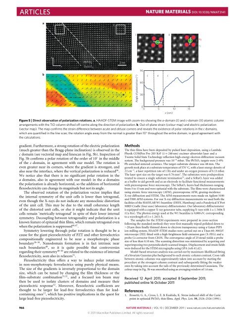
Figure 5 | Direct observation <strong>of</strong> <strong>polarization</strong> <strong>rotation</strong>s. a, HAADF-STEM image with zoom-<strong>in</strong>s show<strong>in</strong>g the a-doma<strong>in</strong> (I) and c-doma<strong>in</strong> (II) atomic column<br />
arrangements with the TiO column shifted <strong>of</strong>f-centre along the direction <strong>of</strong> <strong>polarization</strong>. b, Out-<strong>of</strong>-plane stra<strong>in</strong> (colour map) and electric <strong>polarization</strong><br />
(vector map). The map confirms the stra<strong>in</strong> difference between acute and obtuse corners and reveals the existence <strong>of</strong> polar <strong>rotation</strong>s <strong>in</strong> the c doma<strong>in</strong>s,<br />
which are quantified <strong>in</strong> the l<strong>in</strong>e scan; the <strong>rotation</strong> angle away from the normal is greater than 10 ◦ throughout the entire doma<strong>in</strong>, <strong>in</strong> good agreement with<br />
the calculations.<br />
gradient. Furthermore, a strong <strong>rotation</strong> <strong>of</strong> the electric <strong>polarization</strong><br />
(much greater than the Bragg-plane <strong>in</strong>cl<strong>in</strong>ation) is observed <strong>in</strong> the<br />
c doma<strong>in</strong> (see vectorial map and l<strong>in</strong>escan <strong>in</strong> Fig. 5b). Inspection <strong>of</strong><br />
Fig. 5b confirms a polar <strong>rotation</strong> <strong>of</strong> the order <strong>of</strong> 10 ◦ <strong>in</strong> the middle<br />
<strong>of</strong> the c-doma<strong>in</strong>, <strong>in</strong> agreement with our model. The <strong>rotation</strong> is<br />
even greater near its corners, where the gradient is strongest, and<br />
also near the <strong>in</strong>terface, where the vertical <strong>polarization</strong> is reduced 46 .<br />
We notice also that there is no significant polar <strong>rotation</strong> <strong>in</strong> the<br />
a doma<strong>in</strong>s, also <strong>in</strong> agreement with our model: <strong>in</strong> the a doma<strong>in</strong>s<br />
the <strong>polarization</strong> is already horizontal, so the addition <strong>of</strong> horizontal<br />
flexoelectricity can change its magnitude but not its angle.<br />
The observed <strong>rotation</strong> <strong>of</strong> the <strong>polarization</strong> vector implies that<br />
the <strong>in</strong>ternal symmetry <strong>of</strong> the unit cells is lower than tetragonal,<br />
even though the X-rays do not <strong>in</strong>dicate any monocl<strong>in</strong>ic distortion<br />
<strong>of</strong> the unit cell. This may be due to the small coherence length<br />
<strong>of</strong> the distorted unit cells, or else it might <strong>in</strong>dicate that the unit<br />
cells rema<strong>in</strong> ‘metrically tetragonal’ <strong>in</strong> spite <strong>of</strong> their lower <strong>in</strong>ternal<br />
symmetry. Decoupl<strong>in</strong>g between tetragonality and <strong>polarization</strong> is a<br />
known feature <strong>of</strong> epitaxial th<strong>in</strong> <strong>films</strong>, which rema<strong>in</strong> tetragonal even<br />
when the <strong>polarization</strong> is suppressed 46,47 .<br />
Symmetry lower<strong>in</strong>g through polar <strong>rotation</strong> is thought to be a<br />
cause for the giant piezoelectricity <strong>of</strong> PZT and other <strong>ferroelectric</strong>s<br />
compositionally eng<strong>in</strong>eered to be near a morphotropic phase<br />
boundary 28–30 . Nanodoma<strong>in</strong> formation is <strong>in</strong> fact <strong>in</strong>tr<strong>in</strong>sic near<br />
such boundaries 48 , so it is quite possible that controversies<br />
regard<strong>in</strong>g their symmetry 48–50 are related to the existence <strong>of</strong> <strong>in</strong>ternal<br />
flexoelectricity, seen also <strong>in</strong> relaxors 51 .<br />
<strong>Flexoelectric</strong>ity thus <strong>of</strong>fers a way to <strong>in</strong>duce polar <strong>rotation</strong>s<br />
<strong>in</strong> non-morphotropic <strong>ferroelectric</strong>s us<strong>in</strong>g purely physical means.<br />
The size <strong>of</strong> the gradients is <strong>in</strong>versely proportional to the doma<strong>in</strong><br />
size, which can be tuned by chang<strong>in</strong>g the film thickness or the<br />
film–substrate comb<strong>in</strong>ation 31,32 , and a focused ion beam may<br />
then be used to isolate clusters <strong>of</strong> doma<strong>in</strong>s and measure their<br />
piezoelectric response 52 . Moreover, flexoelectric coefficients are<br />
thought to be larger for lead-free <strong>ferroelectric</strong>s than for leadconta<strong>in</strong><strong>in</strong>g<br />
ones 12 , which has positive implications <strong>in</strong> the quest for<br />
large lead-free piezoelectricity.<br />
Methods<br />
The th<strong>in</strong> <strong>films</strong> have been deposited by pulsed laser deposition, us<strong>in</strong>g a Lambda<br />
Physik COMPex Pro 205 KrF (λ = 248 nm) excimer ultraviolet laser and a<br />
Twente Solid State Technology reflection high-energy electron diffraction vacuum<br />
system. The background pressure was 10 −8 mbar. The PbTiO 3 targets were 2–8%<br />
Pb-enriched s<strong>in</strong>tered ceramics. The target–substrate distance was 48 mm. The<br />
growth took place at a substrate temperature <strong>of</strong> 570 ◦ C, with a laser energy density <strong>of</strong><br />
2 J cm −2 , a laser repetition rate <strong>of</strong> 1 Hz and under an oxygen pressure <strong>of</strong> 0.13 mbar.<br />
The laser spot size on the target was 0.76 mm 2 . The substrates were predeposition<br />
treated to ensure a s<strong>in</strong>gle substrate term<strong>in</strong>ation 53 , and a SrRuO 3 layer was added<br />
as a buffer to aid growth and as an electrode to facilitate functional measurements<br />
with piezoresponse force microscopy. The SrRuO 3 layers had thicknesses rang<strong>in</strong>g<br />
from 5 to 15 nm and were epitaxial with the substrate. The <strong>films</strong> were characterized<br />
us<strong>in</strong>g atomic force microscopy (AFM), piezoresponse AFM, graz<strong>in</strong>g-<strong>in</strong>cidence<br />
X-ray diffraction and STEM. The AFM measurements were made on Agilent 5100<br />
and 5500 AFM systems. For our X-ray diffraction measurements we used both the<br />
facilities <strong>of</strong> the HASYLAB W1 beaml<strong>in</strong>e (DESY, Hamburg) and a Panalytical X’Pert<br />
MRD Cradle (four axes) laboratory diffractometer. Our laboratory diffractometer<br />
is equipped with a copper X-ray generator tube, supply<strong>in</strong>g X-rays with λ = 1.5406 Å<br />
(Cu Kα). The photon energy used at the W1 beaml<strong>in</strong>e is 9,800 eV, correspond<strong>in</strong>g<br />
to a wavelength <strong>of</strong> λ = 1.2651 Å.<br />
The samples for the STEM experiments were prepared <strong>in</strong> cross-section<br />
follow<strong>in</strong>g the standard method: they were first manually tripod-polished down to<br />
∼20 µm then f<strong>in</strong>ally th<strong>in</strong>ned down to electron transparency us<strong>in</strong>g a Gatan PIPS<br />
ion mill<strong>in</strong>g system. HAADF-STEM studies were carried out on a Titan 60–300 kV<br />
microscope (FEI) fitted with a high-brightness field-emission gun (X-FEG) and a<br />
probe Cs corrector from CEOS. The convergence angle <strong>of</strong> 25 mrad yields a probe<br />
size <strong>of</strong> less than 0.10 nm. The scann<strong>in</strong>g distortion was m<strong>in</strong>imized by acquir<strong>in</strong>g and<br />
superimpos<strong>in</strong>g two perpendicularly scanned images. Displacement and stra<strong>in</strong> fields<br />
were deduced for the STEM micrographs us<strong>in</strong>g GPA (refs 41,42).<br />
Model-based structure analysis was carried out by maximum-likelihood fitt<strong>in</strong>g<br />
<strong>of</strong> a bivariate Gaussian plus background to each atomic-column contrast. Cross-talk<br />
between atomic columns was approximately taken <strong>in</strong>to account by start<strong>in</strong>g the<br />
procedure at the strongest column contrast and subsequently fitt<strong>in</strong>g the weaker<br />
ones by tak<strong>in</strong>g <strong>in</strong>to account the tails <strong>of</strong> the previously determ<strong>in</strong>ed Gaussians. The<br />
colour map <strong>in</strong> Fig. 5b was smoothed us<strong>in</strong>g an averag<strong>in</strong>g w<strong>in</strong>dow <strong>of</strong> 1.6 nm.<br />
Received 12 April 2011; accepted 8 September 2011;<br />
published onl<strong>in</strong>e 16 October 2011<br />
References<br />
1. Rossetti, G. A., Cross, L. E. & Kushida, K. Stress <strong>in</strong>duced shift <strong>of</strong> the Curie<br />
po<strong>in</strong>t <strong>in</strong> epitaxial PbTiO 3 th<strong>in</strong> <strong>films</strong>. Appl. Phys. Lett. 59, 2524–2526 (1991).<br />
966 NATURE MATERIALS | VOL 10 | DECEMBER 2011 | www.nature.com/naturematerials<br />
© 2011 Macmillan Publishers Limited. All rights reserved