TW 82 Operating Manual - Fisher
TW 82 Operating Manual - Fisher
TW 82 Operating Manual - Fisher

Create successful ePaper yourself
Turn your PDF publications into a flip-book with our unique Google optimized e-Paper software.
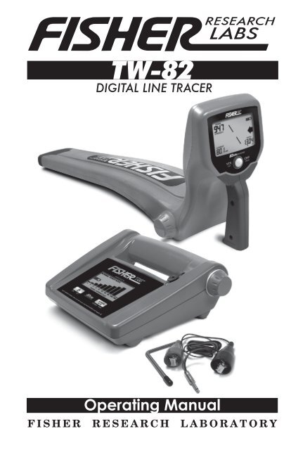
<strong>TW</strong>-<strong>82</strong>DIGITAL LINE TRACER<strong>Operating</strong> <strong>Manual</strong>F I S H E R R E S E A R C H L A B O R A T O R Y
CONTENTSIntroduction...........................................................................pg. 3Transmitter ...........................................................................pg. 4-6Receiver...................................................................................pg. 7-9Specifications.........................................................................pg. 10Warranty.................................................................................pg. 11Accessories.............................................................................pg. 12
INTRODUCTIONThe <strong>TW</strong>-<strong>82</strong> Digital Line Tracer components include a Transmitter,Receiver, ground-rod assembly, carrying case (soft or optionalhard case) and an operator’s manual. The <strong>TW</strong>-<strong>82</strong> is a singlefrequency line tracer.The <strong>TW</strong><strong>82</strong> is an active locating line tracer. There are threelocating methods that an operator can use to trace a utility.1. The conductive method is the preferred method, as a strongsignal is transmitted directly through the utility line. Aconductive trace is accomplished by making a direct electricalconnection to the utility with a clamp.2. When a direct electrical connection is not available, but theoperator has some knowledge of where one point of the utilitymay be, the transmitter can be placed on the ground overthe utility. With this inductive tracing method, the signal istransmitted through the ground and couples magnetically on toutilities in close proximity.3. A third method is also inductive, but uses the optional couplingclamp. A coupling clamp can be used when a utility is exposed,but a direct electrical connection is not possible. By fitting thecoupling clamp around the utility, the signal transmits throughthe air and couples magnetically on to the utility.Never make direct contact with electrical or communication linesthat are in service. To trace such lines in service, perform aninductive trace, either with or without the coupling clamp.13
<strong>TW</strong>-<strong>82</strong> TRANSMITTER<strong>TW</strong>-<strong>82</strong> TransmitterThe Transmitter has two controls: & .The Button has a dual function:1. When the Transmitter is powered on, switchesthe device between normal (1/4 watt) and high (1.0 watt)output.2. With the Transmitter powered off:A. Press-and-hold to program the AutoPower-Down feature.4Successive presses of will show a flashingbattery indicator, followed by a blank screen or theilluminated battery indicator.• An illuminated battery indicator means thatAuto Power-Down is activated.• A blank screen means that Auto Power-Downis deactivated.B. After you release , the transmitterpower will turn on.With the Auto Power-Down feature activated, theTransmitter will automatically turn off 60 minutes afterthe last key-pad press by the user. This is a battery savingfeature. The Transmitter will warn of power-down asdescribed on the following page.
<strong>TW</strong>-<strong>82</strong> TRANSMITTERLow Battery Power-Down WarningWhen the Transmitter batteries are near the end of theiruseful life, the Transmitter will warn the operator beforeshutting down.Five minutes before shutting down, the Transmitter willalternately stop and start transmitting at approximately onesecondintervals. The operator using the Receiver, even at adistance from the Transmitter, will notice the signal turningon and off before the power turns off completely.Accessory Output1. Flip up the black protective cover to expose the AccessoryOutput.2. Plug in the Cable Jack for conductive tracing.When the conductive tracing cable is connected, SignalCurrent will be displayed. The Signal Current Bar Graphshows the quality of the connection.Automatic Load Impedance Matching adjusts output toprovide full rated power over a wide range of loads (e.g.utility types and conditions). It is tolerant of both dry(high resistance) and shunted (low resistance) groundconnections.The Transmitter has a built-in antenna for inductivelocating. When the Cable Jack is not connected, the inductiveantenna automatically engages and begins transmitting.When locating inductively, the Signal Current Bar Graphwill not be displayed, as there is no conductive trace load tobe measured.WARNING: Do not handle output leads unless power is off.ELECTRIC SHOCK HAZARD: Servicing to be performed byqualified personnel only.NEVER connect conductive cables to an energized powerline.5
<strong>TW</strong>-<strong>82</strong> TRANSMITTERINDUCTIVE LOCATING6Inductive locating is most effective withthe Transmitter straddling the utility asillustrated, with the utility perpendicular tothe Transmitter’s batteries.If the utility direction is unknown,place Transmitter on the ground, poweron, and sweep the Receiver a complete360º around the Transmitter, keepingat least a 25-foot (8-meter) distancebetween the Transmitter and Receiver.If unsuccessful, move the Transmitterto another location. When located, theReceiver’s azimuth indicator will showthe direction of the utility.In inductive mode, the Transmitter’s LCD willnot display Signal Current. When the groundrod is plugged in, the Signal Current displaywill illuminate.CONDUCTIVE LOCATING1. Connect the Ground Rodassembly to the Transmitter.2. Push the Ground Rod intothe earth at a 90º angle to thedirection of the utility.3. Connect the red clamp to thenon-energized utility.4. Connect the black clamp to theGround Rod.Be sure not to place the wiresover any other utility.5. Move at least 25 feet (8 meters) away from theconnection point.6. Sweep the Receiver in a circle around the connectionpoint.7. Using information provided on the display,find the areas that need to be traced and analyze thesituation in more detail to find the buried utility.
<strong>TW</strong>-<strong>82</strong> RECEIVER<strong>TW</strong>-<strong>82</strong> ReceiverSingle Button OperationDisplay• Power-Up:• Volume Control:• Power-Down:Press Button to turn ONTap the Button to adjust volume1. Mute2. Very Low3. Low4. Medium5. HighContinued presses of the button cyclesback to setting #1.Press-and-Hold Button to turn OFF1. Signal Strength: Indicates your proximity to the center of theelectromagnetic field emitted by the utility.999: maximum value0: minimum valueYou may find different locations where theSignal Strength value is high. Use thisreading as a relative indicator as to wherethe utility is located. Signal Strength isstrongly influenced by the depth of theutility.7
<strong>TW</strong>-<strong>82</strong> RECEIVERDisplay - Continued2. Battery Strength: When battery lifedeclines to less than 1 hour (estimated)of operation the battery indicator outlinewill be illuminated with no segments.When the batteries reach the end of theiruseful life, the screen will go blank and thebattery icon will flash before the Receiver shuts off. Expect about60 hours of battery life from a set of two D-cell alkaline batteries.3. Left/Right& Over-Target: These indicators show your position relative tothe center of the electromagnetic field.Move to Move to You are overthe left the right the targetAudio: When you move within a 45º angle of the center of theelectromagnetic field, the audio pitch will change.The pitch increases as you approach the utility and is highestover the top of the utility. Outside the 45º zone, the pitch andvolume do not change.HIGHEST PITCH & VOLUMEDIRECTLY OVER UTILITYCONSTANTPITCH BEYOND 45°PITCH INCREASESAS YOU APPROACH THE UTILITYVOLUME DECREASES WITH DISTANCE FROM UTILITY45°CONSTANTPITCH BEYOND 45°When you are standing to the right of the utility, you will hear aconstant tone, and to the left, a pulsating sound.4. Azimuth: These arrows indicate the utility’s path relative toyour position. When you are closeto, or over, the suspectedtarget, rotate the deviceand notice the arrows.8
<strong>TW</strong>-<strong>82</strong> RECEIVER5. Current Measure:mA (miliAmperes) of currentflowing on the conductor.Use Current Measure asan aid for distinguishingutilities in close proximity.The Current Measure willgenerally be the highest onthe utility you are connecteddirectly to, regardless of the utility’s depth.6. DepthDepth reading isonly accurate if theelectromagnetic field isperfectly round.currentcurrentdepthdepthThe electromagnetic fieldmust have enough energyfor the device to accuratelycalculate the depth. Theweaker the signal strength,the less reliable the depth indicator. For this reason, depthreadings for inductively located utilities will tend to be lessaccurate than conductively located ones.The depth reading is the distance between the tip of Receiverblade and the center of the electromagnetic field. The center of theelectromagnetic field is generally the center of the utility. The only100% reliable method for determining depth is to hand-excavate.Auto Power-Down, ReceiverWhen 90 minutes have passed without the operator pressing thecontrol button, the Receiver will automatically power down.• Lower left of the display will indicate “OFF”.• Lower right of the display will count down from 10 to 0.• The Transmitter will then turn off.To stop Auto Power-Down, press the button once.9
SPECIFICATIONSRECEIVERFrequency......................................... <strong>82</strong>.175 kHzLeft/Right Guidance........................ Audible and visualAzimuth Indicator........................... VisualOver-Target Indicator...................... Visual and audibleBattery Status................................. VisualSignal Strength Indicator............... Numeric display & audibleSignal Current Measurement......... Numeric display, automaticDepth Measurement........................ Numeric display, automaticBattery Type.................................... Two D-cell batteries (included)Battery Life...................................... 60 hours, approximateWeight, with batteries..................... 3.60 lbsTRANSMITTEROutput Frequency.............................<strong>82</strong>.175 kHzOutput Power (nominal)...................Normal Setting = 0.25 wattHigh Setting = 1.0 wattConductive Tracing...........................2 to 3,000 ohms, normal power-6dB.....................Magnetic Strength............................2 to 8,000 ohms, high power-6dBInductive Tracing..............................15 Vm 2 , normal powerMagnetic Strength............................25 Vm 2 , high powerBattery Type.....................................Four D-cell batteries (included)Battery Life.......................................Over 100 hours in normal power modeWeight, with batteries......................4 lbsENVIRONMENTALIngress Protection Rating................IP65 (stands up to water jets)<strong>Operating</strong> Temperature Range........-4ºF to 140ºF (-20ºC to +60ºC)Relative Humidity............................0 to 95% noncondensingShipping Weight (packaged).............17.5 lbsField Carry Weight, w/accessories...15.5 lbs**Includes Carry Case, Batteries, Ground Rod and Conductive Tracing Cables<strong>Fisher</strong> Research Laboratory does not warrant suitability to specific use. <strong>Fisher</strong>Research Laboratory shall in no event be liable for any direct, incidental,consequential or indirect damages.10
Q U A L I T Y<strong>Fisher</strong> detectors are renowned for their quality.Each detector is hand crafted in the USA with prideP E R F O R M A N C EThe worldwide underground utility industry relies on <strong>Fisher</strong>.Our instruments are durable, dependable and locate deeper.R E P U T A T I O N<strong>Fisher</strong> produced the first patented metal detector in 1931. Forover 80 years, the <strong>Fisher</strong> logo has been a mark of excellence.2 - YEAR LIMITED WARRANTYProof of purchase is required to make a claim under this warranty.NOTE TO CUSTOMERS OUTSIDE THE U.S.A.This warranty may vary in other countries, check with yourdistributor for details.Factory warranty follows the channel of distribution.Warranty does not cover shipping costs.S E R V I C EShould you have any questions or problems, contact:FISHER RESEARCH LABORATORY1465-H Henry Brennan, El Paso, Texas 79936Tel 1800-685-5050 Fax 915-225-0336www.fisherlab.com email: info@fisherlab.comAccording to FCC part 15.21 Changes or Modifications made to this devicenot expressly approved by the party responsible for compliance could voidthe users authority to operate this equipment.Not to be used with conductive tracing cables longer than 6.5’ ( 1.98 m)11
<strong>TW</strong>-<strong>82</strong> ACCESSORIES3 InchCoupling Clamp– CCLAMP-3Useful for in-service andelectrical power line tracingwhen a metal-to-metal hookup isnot possible5 InchCoupling Clamp– CCLAMP-5Useful for in-service andelectrical power line tracingwhen a metal-to-metal hookup isnot possibleHard Carry Case– 1802050000Shock absorbent protective hardcarrying case with contouredfoam insert custom made tohouse the <strong>TW</strong><strong>82</strong>.35” x 7” x 16”<strong>Fisher</strong> Sonde SignalTransmitter <strong>82</strong>kHz– SONDE-<strong>82</strong>.175Small transmitter used to tracethe path of non-metallic pipesand locate blockage in lines.Sonde is inserted into a pipe orduct by means of a push rod andlocated using a <strong>Fisher</strong> receiver.• Rugged Design• Long Battery Life• Outstanding Distance & DepthLocate up to 15’ deep• <strong>Operating</strong> Frequency: <strong>82</strong> kHz• Weight 6.4 oz• Length 6”• Diameter 2”• Battery Life: 70 hrs• <strong>Operating</strong> Temperature-20 to +60 C (4° to 140°F)• End Cap Thread 3/8”-16 x 3/4”M<strong>TW</strong><strong>82</strong> 101510