Fisher F4 Printer
Fisher F4 Printer
Fisher F4 Printer

You also want an ePaper? Increase the reach of your titles
YUMPU automatically turns print PDFs into web optimized ePapers that Google loves.
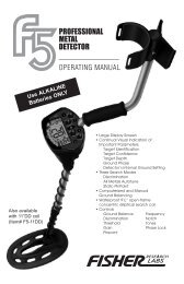
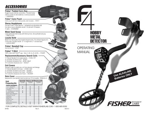
ACCESSORIES<strong>Fisher</strong> ® Padded Carry BagRugged double stitched construction. Includes handyexterior pocket for extra batteries or small accessories.– 103693000C<strong>Fisher</strong> ® Camo PouchCamo pouch with two inside pockets, belt included. – PCH-FStereo HeadphonesUse with <strong>Fisher</strong> ® metal detectors. Lightweight and adjustable withtrue stereo sound, adjustable volume, 1/4 jack with 1/8 adaptor,4’ cable. – 9720950000Metal Sand ScoopLarge galvanized metal scoop with filtering holes. Strong Rubberized grip.– SAND SCOOPLesche KnifeMade from high quality heat-treated tempered steel. The ultimate digging tool.Comes with a durable sheath. 12" in length with a 7" serrated blade.– LESCHE KNIFE<strong>Fisher</strong> ® Baseball CapOne size fits all. – FCAP<strong>Fisher</strong> ® T-Shirt100% cotton with <strong>Fisher</strong> ® Logo. Sizes: S, M, LG, XL & XXL – FTSHIRTReplacement/Accessory Search Coils11” Biaxial Standard Coil (replacement) – 11COIL-<strong>F4</strong><strong>F4</strong>” Concentric Accessory Coil – 4COILF8” Concentric Accessory Coil – 8COIL-7BLKF10” Concentric Accessory Coil – 10COILFCoil CoversSpecially made to protect your coil from abrasion and damage.11” Biaxial Standard Coil Cover – COVER-11DD4” Concentric Accessory Coil Cover – 4COVER8” Concentric Accessory Coil Cover – 8COVER-710” Concentric Accessory Coil Cover – 10COVERRain CoverNeoprene rain cover specially made to protect your F2 from weather– RAINCOV-F2GoldProspecting KitsOPERATINGMANUALUse ALKALINEBatteries ONLYFOR COMPLETE DETAILS VISIT WWW.FISHERLAB.COM • 1-800-685-5050M<strong>F4</strong>B Rev.4 050313
TABLE OF CONTENTSNOTESTerminology . . . . . . . . . . . . . . . . . . . . . . . . . . . . . . . . . . . . . .3Assembly . . . . . . . . . . . . . . . . . . . . . . . . . . . . . . . . . . . . . . . .4Batteries . . . . . . . . . . . . . . . . . . . . . . . . . . . . . . . . . . . . . . . . .5Headphones . . . . . . . . . . . . . . . . . . . . . . . . . . . . . . . . . . . . .5Quick-Start Demo . . . . . . . . . . . . . . . . . . . . . . . . . . . . . . .6-7Control Panel . . . . . . . . . . . . . . . . . . . . . . . . . . . . . . . . . .8-11Sensitivity . . . . . . . . . . . . . . . . . . . . . . . . . . . . . . . . . . . .8Auto Tune . . . . . . . . . . . . . . . . . . . . . . . . . . . . . . . . . . .8Discrimination Control . . . . . . . . . . . . . . . . . . . . . . . . .9Pinpoint . . . . . . . . . . . . . . . . . . . . . . . . . . . . . . . . . . . .10Disc . . . . . . . . . . . . . . . . . . . . . . . . . . . . . . . . . . . . . . .10Notch . . . . . . . . . . . . . . . . . . . . . . . . . . . . . . . . . . . . . .11Ground Balancing . . . . . . . . . . . . . . . . . . . . . . . . . . . . .12-13Quick Ground Balancing . . . . . . . . . . . . . . . . . . . . .134-Tone Audio System . . . . . . . . . . . . . . . . . . . . . . . . . . . . .14Depth and Target Display . . . . . . . . . . . . . . . . . . . . . .15-16Target Readout Table . . . . . . . . . . . . . . . . . . . . . . . .16DD Coil Characteristics . . . . . . . . . . . . . . . . . . . . . . . . . . .17Bottle Cap Discrimination . . . . . . . . . . . . . . . . . . . . .17Sweet Spot . . . . . . . . . . . . . . . . . . . . . . . . . . . . . . . . .17Sensitivity Adjustment . . . . . . . . . . . . . . . . . . . . . . . . . . . . .18Electromagnetic Interference . . . . . . . . . . . . . . . . .18Severe Ground Conditions . . . . . . . . . . . . . . . . . . . .18Search Techniques . . . . . . . . . . . . . . . . . . . . . . . . . . . . . . .19Target Verification . . . . . . . . . . . . . . . . . . . . . . . . . . .19Pinpointing with motion modes . . . . . . . . . . . . . . . .19Target Pinpointing (No motion) . . . . . . . . . . . . . . . . . . . . .20Coil Drift . . . . . . . . . . . . . . . . . . . . . . . . . . . . . . . . . . . .10Treasure Hunter’s Code of Ethics . . . . . . . . . . . . . . . . . . .21Coil Drift . . . . . . . . . . . . . . . . . . . . . . . . . . . . . . . . . . . .10Warranty . . . . . . . . . . . . . . . . . . . . . . . . . . . . . . . . . . . . . . .21Coil Drift . . . . . . . . . . . . . . . . . . . . . . . . . . . . . . . . . . . .10Accessories . . . . . . . . . . . . . . . . . . . . . . . . . . . . . .Back PageCoil Drift . . . . . . . . . . . . . . . . . . . . . . . . . . . . . . . . . . . .10223
NOTES22TERMINOLOGYThe following terms are used throughout the manual, and are standardterminology among treasure hunters.ELIMINATIONReference to a metal being "eliminated" means that the detector will notemit a tone, nor light up an indicator, when a specified object passesthrough the searchcoil’s detection field.DISCRIMINATIONWhen the detector emits different tones for different types of metals, andwhen the detector "eliminates" certain metals, we refer to this as thedetector "discriminating" among different types of metals.Discrimination is an essential feature of professional metal detectors.Discrimination allows the user to ignore trash and other undesirableobjects.RELICA relic is an object of interest by reason of its age or its association withthe past. Many relics are made of iron, but can also be made of bronzeor precious metals.IRONIron is a common, low-grade metal that is an undesirable target in certainmetal detecting applications. Examples of undesirable iron objects areold cans, pipes, bolts and nails.Sometimes, the desired target is made of iron. Property markers, forinstance, contain iron. Valuable relics can also be composed of iron;cannon balls, old armaments, and parts of old structures and vehiclescan also be composed of iron.FERROUSMetals which are made of, or contain, iron.PINPOINTINGPinpointing is the process of finding the exact location of a buried object.Long-buried metals can appear to the eye exactly like the surroundingsoil, and can therefore be very hard to isolate from the soil.PULL-TABSDiscarded pull-tabs from beverage containers are an especiallybothersome trash item for treasure hunters. They come in manydifferent shapes and sizes. Pull-tabs can be eliminated fromdetection, but some other valuable objects can have a magneticsignature similar to pull-tabs, and will also be eliminated whendiscriminating out pull-tabs.GROUND BALANCEGround Balancing is the ability of the detector to ignore, or "see through"the earth’s naturally occurring minerals, and only sound a tone when ametal object is detected. The Gold Bug incorporates proprietary circuitryand programming to eliminate false signals from severe ground conditions.3
ASSEMBLYCaution:Forcing in MIDDLE STEM with CAM LOCK raised may form a burr oncamlock. If this happens, remove burr with knife to allow insertion.TREASURE HUNTER’S CODE OF ETHICS:●1●2●3●4●5●6●7●8●9●10Position detector upright.Rotate the LOCKING COLLAR fully in thecounterclockwise direction.Insert your finger inside the tube and make sure theINTERNAL CAM LOCK is flush with the inside of the tube.S-RODLOCKINGCOLLARInsert the MIDDLE STEM into theS-ROD, with the SILVER BUTTONpointed upward●4Rotate the MIDDLE STEM until theSILVER BUTTON locates in the hole.Twist the LOCKING COLLAR fully in the clockwisedirection until it locks.Repeat this process on the LOWER STEM.Using the BOLT and KNURLED KNOB, attachthe SEARCHCOIL to the LOWER STEM.Adjust the LOWER STEM to a length that lets youmaintain a comfortable upright posture, with your armrelaxed at your side, and the SEARCHCOIL parallel to theground in front of you.Wind the CABLE securely around the STEMS.●11 Connect CABLE PLUG to housing.Do not twist the Cable or Plug. Turn Locking Ring only. Useminimal finger pressure to start the threads. Do not crossthread.When the Locking Ring is fully engaged over thethreaded connector, give it a firm turn to make sure that itis very tight. When the Locking Ring is fully engaged over thethreaded connector, it may not cover all of the threads.●12 Tighten both LOCKING COLLARS.Armrest AdjustmentIf you wish to change theposition of the armrest, removethe screw and move the armrestto one of the alternate holelocations.●2INTERNALCAM LOCK●3SILVER BUTTONMIDDLE ●4STEMMIDDLE STEM●5S-RODBatteryCompartment(back side)CablePlugArmrestLockingCollarSearchCoilCableKnurledKnobS-RodHand-gripHeadphoneJackMiddleStemLockingCollar*BiaxialSearchcoil•Always check Federal, State, County and local laws before searching.•Respect private property and do not enter private property without the owner’s permission.•Take care to refill all holes and leave no damage.•Remove and dispose of any and all trash and litter found.•Appreciate and protect our inheritance of natural resources, wildlife and private property.•Act as an ambassador for the hobby, use thoughtfulness, consideration and courtesyat all times.•Never destroy historical or archaeological treasures.•All treasure hunters may be judged by the example you set; always conduct yourselfwith courtesy and consideration of othersAccording to FCC part 15.21 Changes or Modifications made to this device not expressly approved by theparty responsible for compliance could void the users authority to operate this equipment.This device complies with FCC Part 15 Subpart B Section 15.109 Class B.5-YEAR LIMITED WARRANTYThe <strong>F4</strong> metal detector is warranted against defects in materials andworkmanship under normal use for five years from the date of purchase tothe original owner.Damage due to neglect, accidental damage or misuse of this product is notcovered under this warranty. Decisions regarding abuse or misuse of thedetector are made solely at the discretion of the manufacturer.Proof of Purchase is required to make a claim under this warranty.Liability under this Warranty is limited to replacing or repairing, at our option,the metal detector returned, shipping cost prepaid to <strong>Fisher</strong> Labs. Shippingcost to <strong>Fisher</strong> Labs is the responsibility of the consumer.To return your detector for service, please first contact <strong>Fisher</strong> Labs for a ReturnAuthorization (RA) Number. Reference the RA number on your package andreturn the detector within 15 days of calling to:1465-H Henry Brennan Dr.El Paso, TX 79936Phone: 915-225-0333 ext.118Warranty coverage does not include the cost of transporting the detectorback to an owner who is located outside of the United States of America.NOTE TO CUSTOMERS OUTSIDE THE U.S.A.This warranty may vary in other countries, check with your distributor for details.Warranty does not cover shipping costs.Copyright© 2013All rights reserved, including the right to reproduce this book, or parts thereof, in any form.<strong>Fisher</strong> ® is a registered trademark of <strong>Fisher</strong> Research Labswww.fisherlab.comMADE IN USA* Note: Very tall users can purchase the optional Extended Lower Stem (TUBE5X), for extended reach.4 21
TARGET PINPOINTING (no-motion PINPOINT mode)After you have identified a target using a motion mode of detection,press the PINPOINT pad to identify the target’s exact location. Thistechnique can yield more information about the target’s shape andsize and also find its exact location to facilitate excavation.Pinpoint (in no-motion mode) as follows:1. Position the searchcoil just barely off the ground, and to the side ofthe target.2. Press PINPOINT pad and raise the searchcoil about 2 inches. Liftingthe searchcoil away from the ground makes the ground signal gonegative, so the machine is silent.3. Now move the searchcoil slowly across the target, and you canlocate it by the sound. The target is located directly under wherethe sound is loudest.Narrow It Down:1. To narrow the response further, position thecenter of the searchcoil near the center of theresponse pattern, but not directly over the center.2.Press PINPOINT pad again.3. Repeat this narrowing procedure to narrow thefield of detection further.Note: Depth indication is less accurate afternarrowing.20COIL DRIFTIf you plan to use the PINPOINT mode for continuoussearching, realize that drift will occur over time,causing the detector to gain or lose sensitivity.Periodic retuning of the detector is requiredto minimize drift; press PINPOINT to retune.Temperature change will cause thecoil to drift in point mode.If the detector moves from acooler to a warmerenvironment, the detectormay emit a constant toneuntil the temperaturestabilizes; if so, retune.If the detector movesfrom a warmer to acooler environment,the detector may losesensitivity (remainingquiet); if so, retune.BATTERIESTwo 9-Volt batteries aresupplied with the F2.The batteries have beeninserted backwards in thecompartment for storageduring transportation.Please remove batteries,turn them around, and installcorrectly.Use ALKALINE batteriesonly.DO NOT MIX OLD ANDNEW BATTERIES.To install the batteries: 1 Remove the battery coverby disengaging the clip at theback.Do not hinge door upward; pullstraight back2 Align the polarity of the batteries correctly, with the positive "+"toward the coil plug connection, as indicated by the + indicatoron the housing. 3 Insert (2) 9-Volt ALKALINE batteries, with the contacts pointed inward,and press down on the back of the batteries to snap them into place.Some brands of batteries will require moderate force to clear theretaining tabs. 4 Replace the battery door.Most metal detector problems are due to improperly installedbatteries, or the use of non-alkaline or discharged batteries. If thedetector does not turn on, please check the batteries.USING HEADPHONESUsing headphones (not included) improvesbattery life, and prevents the sounds fromannoying bystanders.It also allows you to hear subtle changes in thesound more clearly, particularly if searching in anoisy location. For safety reasons, do not useheadphones near traffic or where otherdangers are present. This device is to be usedwith interconnecting cables/headphonecables shorter than three meters.5
QUICK-START DEMONSTRATIONI. Supplies Needed• A Nail• A Quarter• A Pull-Tab from a beverage can • A Zinc Penny (dated after 1982)• A NickelII. Position the Detectora. Place the detector on atable, with the searchcoil hanging over theedge. (or better, have afriend hold the detector,with the coil off theground).b. Keep the searchcoilaway from walls, floors,and metal objects.c. Remove watches, rings and other jewelry or metal objects fromhands and wrists.d. Turn off appliances or lights that cause electromagneticinterference.e. Pivot the search coil backtoward the detector body.III. Power UpPress the ON/OFF touch pad.IV. Wave each Object over theSearch Coila.Notice a different tone foreach object.Low Tone: NailLow Mid Tone: Pull-TabMedium Tone: Zinc PennyHigh Tone: Quarterb.Motion is required. Objectsmust be in motion over thesearch coil to be detected.V. Press the DISC touch padThe detector will beep and2 “R”’s will appear underthe iron indicators.SEARCH TECHNIQUES (in DISC mode)Target VerificationAfter detecting a target, do thefollowing:1. Walk around the target in acircle.2. While circling the target,continue sweeping thesearchcoil across the target.3. Sweep once every 30° or 40° ofthe circle.If the tone does not changeand the target ID value isconsistent as you circle thetarget, you can be highlyconfident of the target’sidentification.If the tone or target IDchanges as you circle thetarget, you may have multipletargets or an irregularly shapedobject.If the tone completelydisappears at different angles,the target may be trash or alow-value metal.WRONGCORRECTCOIL MOVEMENTWhen swinging the coil, becareful to keep it level withthe ground about 1/2 inchfrom the surface. Never swingthe coil like a pendulum.If you are new to the hobby, dig all targets. With practice in thefield, you will soon identify audible and visual target feedback withcertain types of metal objects.Pinpointing process in motion modes:1. Sweep over target in narrowing side-to-side pattern2. Take visual note of spot on ground where “beep” occurs.3. Step 90° to the side of the target4. Sweep coil over same area, at 90° to 1st sweep pattern.5. This pinpoints the target location with an “X”6 19
SENSITIVITY ADJUSTMENTELECTROMAGNETIC INTERFERENCEUse the Sensitivity Control is to eliminateElectromagnetic Interference (EMI).The <strong>F4</strong> metal detector is an extremely sensitivedevice; the search coil creates its ownmagnetic field and acts like an antenna. Ifyour detector beeps erratically when thesearch coil is motionless, the unit is probablydetecting another electromagnetic field.Common sources of EMI are electric power lines, both suspended and buried,motors, and household appliances like computers and microwave ovens.Some indoor electronic devices, such as dimmer switches used on householdlighting, produce severe EMI and can cause the detector to beep erratically.Other metal detectors also produce their own electromagnetic fields; so ifdetecting with a friend, keep two metal detectors at least 20 feet apart.If the detector beeps erratically, REDUCE THE SENSIT IVITY by pressing theSe nsi ti vity - Pad on the left of the control panel.In most urban environments, you should be able to search without chatter frominterference at the default sensitivity setting (default setting is the sensitivity levelat power-up, 4 bars), or at one level reduced from default. At maximumsensitivity, the <strong>F4</strong> will “chatter” in proximity to underground or overhead powerlines, or to indoor or outdoor electrical devices. In fact, if you notice rapidchatter with the searchcoil near the ground, you may be able to trace theapproximate location of the underground power lines by following the chatter.To manage chatter, which is most likely from electrical interference:1. R ED UCE the S EN SITIVITY until the chatter stops.2. Try sweeping it over the ground.If the <strong>F4</strong> chatters while held still, or held up in the air, it may be muchquieter when sweeping over the ground.183. Operate in AUTOTUNE modeInterference is much more tolerable in this mode, even at high sensitivity.SEVERE GROUND CONDITIONSA secondary use for the Sensitivity Control is to reduce false detection signalscaused by severe ground conditions. While the detector contains circuitry toeliminate the signals caused by most naturally occurring ground minerals, 100%of all ground conditions cannot be anticipated. Highly magnetic soils found inmountainous and gold-prospecting locations can cause the detector to emittones when metal objects are not present. High saline content soils and sandscan sometimes cause the detector to beep when no metal target is present.If the detector emits false, non-repeatable, signals, REDUCE THE SENSITIVITY.QUICK-START DEMONSTRATION (continued)VI. Wave the Nail over the Search Coila. The Nail will not be detected.b. The Nail has been "Discriminated Out."VII. Press the“DISCRIMINATION +”touch pad 3 times.Five “R”s are nowdisplayed.VIII. Wave all objects over theSearch CoilThe Nail and Pull-Tab willnot be detected.The other objects will bedetected with their own distinctive tones.IX. Press the NOTCH touch pad.A flashing “▲” willappear under the IRON-1segment.X. Press the DISCRIMINATION+ touch pad 3 times.The flashing “▲” will moveto the 5¢ segment.XI. Press the NOTCH touchpad againThe “R” will disappear under5¢ segment.XII. Wave the nickel over thesearch coil.The nickel is detected.XIII. Wave the penny over the searchcoil.XIV.Press the NOTCH touch pad twice.The arrow under the 1¢ segment will flash & then the “R” will illuminate.XV. Wave the penny over the search coil again.The penny (the most recently detected item) is eliminated fromdetection.XVI. Press the PINPOINT touch pad.Hold one of the metal objects motionless over the search coil.• All Metal objects are now detected.• One monotone sound indicates the presence of any type of metal.• A 2-digit numerical display indicates approximate target depth, in inches.7
CONTROL PANELThe operating controls are as follows:SENSITIVITY + AND –These controls change the detector’s sensitivity;higher settings enable detection of deepertargets. At power-up, the detector is pre-set to75% of maximum sensitivity. At minimum, thesensitivity is 35% of maximum. With each press ofthe + or – touch pads, the sensitivity level isdisplayed on the bar graph on the left of thedisplay. Upon reaching the minimum or maximumsensitivity setting, the detector will beep twice.While higher levels of sensitivity enable detection of deeper targets,operation at high levels of sensitivity make the detector more susceptibleto electromagnetic interference. Higher sensitivity settings can also leadto false signals in difficult ground conditions. Use lower sensitivity settingsto suppress interference or false signals from soil minerals when necessary.If the detector “Chatters”, reduce sensitivity.AUTO TUNE (All Metal)Press this pad and “ALL METAL” appears on the displayThis mode is a ground-balanced All Metalmotion search mode. This mode offers themaximum amount of sensitivity under mostground conditions. The search coil must be inmotion to detect metal. One monotone soundis emitted. No discrimination or targetidentification is possible in this mode.Use the Sensitivity or Threshold controls to change the sensitivity orbackground hum. Maximum sensitivity to buried metal objects isachieved with a slightly audible background hum.To achieve an audible backg round hum:1. Press AUTO TUNE pad to enter this mode.2. Press Sensitivity + or - pads until you reach a desired setting.This sensitivity setting may be the highest “quiet” setting, or you mayhear a faint background hum.3. Press Threshold + or-pad until you reach a comfortable volume level.The Sensitivity control works like a course adjustment in this mode.The Threshold control works like a fine adjustment in this mode.DD COIL CHARACTERISTICSA DD coil is superior to a concentric coil, but sometimes requires adifferent sweep technique.Advantages are1. Better target separation2. Superior performance in highly mineralized ground3. Broader Sweep- cover more ground with each sweepIf you experience multiple responses on a shallow target, you canraise the coil, or narrow the sweep over known targets to onlyintersect the center section of the coil.BOTTLE CAPSThe disadvantage of the DD coil is its propensity toclassify steel bottle caps as coins.If you hear a high tone in DISC mode and believethat it is a coin, make sure it is not a bottle cap usingthe following method.1. If a repeatable ID# around 68 to 72, then itshould be a dime or copper penny.2. If not in the range of 68 to 72, then:a. Sweep the back end of search coil overthe target. If tone changes from high to alow tone, it is probably a bottle cap.b. Sweep search coil fastacross target.1. If tone and ID-valuedrop, it is probably abottle cap.2. If a bottle cap, thefaster you sweep, thelower the tone.Sweep back endof searchcoil oversuspected bottle cap.(Low Tone = Bottle Cap)SWEET SPOTThe “center” of the DD-Coil is elongated (elliptical) from top tobottom of the coil. With some practice you will find where the centerof this ellipse lies on your coil. Use this center point as a reference inpinpointing.The AUTO TUNE mode must be ground-balanced to eliminate interferingsignals from soil minerals. See the section on ground balancing for adescription of this procedure.8 17
DEPTH AND TARGET DISPLAYCu/10¢: Dimes and pre-1982 pennies willregister here. Older, pre-1982, penniesare composed of copper, which has ametallic signature similar to a dime. Mostcopper coins will register here.Cauti on: The target indications arevisual references. Many other types ofmetal can fall under any one of thesecategories. While the <strong>F4</strong> will eliminateor indicate the presence of mostcommon trash items, it is impossible toaccurately classify ALL buriedobjects.DEPTH INDICATOR:The Depth Indicator is accurate forcoin-sized objects. It indicates thedepth of the target, in inches. Largeand irregularly-shaped objects willyield less reliable depth readingsWhile holding the PinPoint touch pad,and passing over a metal object“depth” will appear next to the one-digitor two-digit number in the middle of thescreen.TWO DIGIT TARGET INDICATORThe Two-digit target indicator, in themiddle of the LCD display, provides a16specific target value to help identifyburied targets more accurately. Withpractice in the field, you will learn toassociate target values with theprobable identification of buried objects.The target value can vary each time thecoil passes over the target, dependingupon the angle of the object and thedistance from the coil.As a starti ng point, refer to thetable below.TARGET ReadoutThe table below lists some commonapproximate target valueequivalents. With experience in thefield, you will recognize many typesof metals by their numeric value.TYPICAL POSSIBLEVALUE OBJECTS0-15 Iron25-28 Pull-Tab Tail (broken off)28-32 Nickel36-42 Pull-Tab (old type)58-62 Zinc, Penny68-72 Dime & Wheat Cent78-83 Quarter86-90 Half Dollar91-95 Silver DollarCONTROL PANEL (continued)DISCRIMINATION (THRESHOLD) + AND –The function of this control depends upon theoperating mode you are in before you pressthese touch pads.AUTO TUNE+ and – will change the threshold sensitivityof the detector in this mode. This Thresholdcontrol operates like a fine adjustment forsetting the sensitivity level and the volumeof the background audible hum. If youcontinue to press +, you will cause thedetector to make a sound, or hum, whenno metal is present. Depending upon skilllevel and environment, some users prefer to operate in AUTO TUNEwith an audible hum active at all times. At such a high “threshold,”faint signals from deeply buried or very small objects will be moreapparent to the user.PINPOINTNot applicable.The + and – touch pads have no function in this mode.DISC+ and – will increase or decrease the level ofdiscrimination. Each press of the pads willcause an “R” to appear or disappear on thedisplay. When the “R” appears, thecorresponding target category will beeliminated from detection. No audible tonenor target-arrow will appear when thesearchcoil passes by an object in acategory with an “R” illuminated. Amaximum of seven “R”s can be displayed, eliminating objects up tothe Zinc-1¢ category. The four right-most target categories cannotbe eliminated from detection.NOTCHWhen Notching-Out a target, the + and – pads will move a flashingarrow to the target category selected fornotching. This feature allows you todiscriminate items selectively across thetarget spectrum. While the “discrimination”control eliminates all targets from left to right,this control allows you to either add backcategories previously eliminated (changingfrom “R” to “blank”) or to selectively eliminatecategories (changing from “blank” to “R”).9
CONTROL PANEL (continued)PINPOINTThis is a static search and static pinpointingmode; no coil motion over the target is requiredto detect metal. This mode is most effective inpinpointing the exact location of small buriedobjects. The detection sensitivity of this mode iscontrolled by the SENSITIVITY + or – touch pads.Discrimination (threshold) + / - has no function.Reduced sensitivity, and thus a smaller searchfield, can also be achieved by pressing thePINPOINT pad while an object is in the coil’sdetection field. The greatest sensitivity to large,deeply-buried objects is achieved with this mode.If you plan to use PINPOINT as a continuoussearch mode, the detector must be groundbalancedbefore searching.DISCThis control invokes motion target identificationsearch modes.Successive presses of the DISC pad will toggleback and forth between the:1. All Metal Discrimination mode: a motionmode where all metal targets are detectedand the:2. Discrimination mode: a motion mode wherethe user can selectively eliminate targetcategories from detection.When the detector powers up, it automatically enters ALL METALDISCRIMINATION mode with no targets eliminated from detection.Press DISC to enter discrimination mode.In order to eliminate more targets from detection, press theDISCRIMINATIO N + pad.To reverse this target elimination, press theDISCRIMINATIO N – pad; illuminated “R”s will disappear.DEPTH AND TARGET DISPLAYREADING THE DISPLAYThe Liquid Crystal Display (LCD) shows thePROBABLE identification of the targetedmetal, as well as the PROBABLE depth ofthe target, in inches.An arrow will illuminate under thetarget category where an object isbest classified, and stay illuminateduntil another target is identified.The detector will normally register arepeating, unchanging targetidentification when a buried target hasbeen located and identified. If, uponrepeated passes over the same spot,the target identification readsinconsistently, the target is probably atrash item, oxidized metal, or too deepto be classified accurately. Withpractice, you will learn to unearth onlythe more repeatable signals.The segment identifications are highlyaccurate, when detecting the objectsdescribed on the label. However, if youregister in a given category for anunknown buried object, you could bedetecting a metallic object other thanthe object described on the label, butwith the same metallic signature. Also,the greater the distance between thetarget and the coil, the less accuratethe target identification.GOLD TARGETS Gold objects will registeron the left side of the LCD scale. Goldwill register depending upon its size. Thesmaller the gold object, the further to theleft it will register.Iron or 5¢/PT.Medium-sized gold items will registerunder PT or S-cap.Large go ld items will register underS-cap or Zinc.SILVER TARGETS: Silver objects willnormally register to the right of the scale,under 10¢, 25¢, 50¢, or $1, dependingon the size of the object. The larger theobject, the farther to the right it willregister.IRON: Ferrous objects will register onthe far-left side of the targetidentification scale. 1, or 2 indicatesthe relative size of iron objects. Smallnails, for instance, will usually illuminatethe Iron-1 arrow whereas largestructural ferrous objects will usuallyilluminate the Iron-2 arrow.Objects in this category could beworthless scrap, or a more valuable ironrelic.5¢/PT: Nickels and most newer pulltabs(thosethat stay attached to thecan) will register here.PT(pull-tabs): Pull-tabs from olderbeverage cans will register here. Fewnewer pull-tabs will also register here.Many gold rings will also register here.SC (Screw Caps): Screw caps fromglass bottles will register here. Largegold rings, like a class ring, could alsoregister here. Some non-U.S. coins willalso register here.Go ld flakesZINC/1¢: Newer pennies (post-1982)will register under Iron-1will register here. Many non-U.S. coinsSmall gold items will register underof recent vintage will also register here.10 15
4-TONE AUDIO SYSTEMWhile the LCD (Liquid Crystal Display) is very accurate in identifyingburied objects, the user in the field does not always maintain thedisplay screen in his field of vision. Therefore, we have incorporated anaudio feedback mechanism to alert the user to the nature of buriedobjects. This audio feedback system first alerts the user to the presenceand classification of objects, whose nature and location can beconfirmed using the LCD display.The 4-tone audio target identification system functions only in the motionmodes of operation. The detector must be in the DISCRIMINATIONmode, as indicated on the display. In PINPOINT or AUTOTUNE modes, thedetector will emit only a monotone sound.The detector can sound four different tones, depending on the objectdetected.14LOW TONEFerrous objects, such as iron and steel, will induce a low tone.The smallest gold objects can also induce a low tone.LOW-MIDPull-Tabs, nickels & smaller goldMEDIUM TONENewer pennies (post-1982), larger gold objects, zinc, and smallbrass objects, will induce medium tones. Many recent vintagenon-U.S. currencies will induce medium tones.HIGH TONESilver and copper coins, larger brass objects and older pennies(pre-1982), will induce high tones. Quarters, dimes and otherprecious coins fall into this category.LOW TONENails, Iron Objects,& Smallest Gold ObjectsLOW-MID TONEPull Tabs, Nickels,& Smaller GoldMEDIUM TONEZinc Pennies (Post 1982),Larger Gold ObjectsAudio Target Identification (ATI) classifies metals into four categories.HIGH TONECopper, Silver & BrassCopper Pennies (Pre 1982)CONTROL PANEL (continued)As you sweep the searchcoil over a metal object, a numeric targetidentification will appear in the center of the display. At the same time,the bar graph on the left of the display will indicate the target depth, ininches. See the scale printed on label to left of the bar graph. Thisscale is calibrated to coin-sized objects. If the target is larger than acoin, it can be used to approximate relative target depth.NOTCHThis control allows you to selectively include or exclude targetcategories from detection. The NOTCH control can be invoked fromany search mode. After selecting the categories to notch-in or notchout,the detector will always return to the motion discrimination mode.Notching functions in two ways, manual or automatic.MANUAL NOTCHIf no target arrows are visible, pressing the NOTCH pad will displayan “R” under all target categories currently eliminated and the “▲”under Iron1 will flash.Use the Discrimination + or – pads to move the position of theflashing “▲”. Pressing NOTCH a 2nd time will change the state ofthe “R” under the flashing “▲”; if the “R” was previously illuminated,it will disappear. Conversely, if the “R” was not illuminated, a 2ndpress of the NOTCH pad will illuminate the “R”, causing this categoryto be eliminated from detection.Practice by pressing the NOTCH pad in conjunction with theD iscrimination + and –pads; their function willquickly become obvious.AUTOMATIC NOTCHIf a target has just beendetected and a targetarrow is visible, pressingNOTCH will immediatelyilluminate a flashing “▲”under this category.Press NOTCH a 2nd time toeliminate that targetcategory from detection.This Automatic Notchfeature is a convenient way to quickly eliminate the most recentlydetected target from future detection.11
GROUND BALANCINGWhat is Ground Balancing?Why do I need to Ground Balance?12All soils contain minerals. Signals from ground minerals are often tens orhundreds of times as strong as the signal from a buried metal object.The magnetism of iron minerals, found in nearly all soils, causes onetype of interfering signal. Dissolved mineral salts, found in some soils, areelectrically conductive, causing another type of interfering signal.Ground Balancing is the process by which the metal detector cancelsthe unwanted signals coming from the ground minerals while stilldetecting the signals from buried metal objects. This is accomplishedby calibrating the detector’s phase response, eliminating the signalsfrom ground minerals.When the detector is calibrated to the soil, the result will be deepertarget detection and quieter operation.How to Ground Balance your detector: (Preferred method)Find a patch of ground free of metal1. Rotate the Ground-Balance KNOB 100% clockwise to the Presetposition.2. Press the AUTO TUNE pad. ALL METAL appears on the display.3. Press Sensitivity + pad several times to reach the highest “quiet”setting or a setting with a faint background hum.4. Press Threshold + or – toadjust the audible hum to acomfortable level.5. Physically pump thesearchcoil and detector upand down over the ground.Lift the searchcoil about 6inches above the groundand lower it to within 1 inchof the ground, about onceor twice a second.6. While pumping thesearchcoil over the groundin this fashion, slowly rotatethe KNOB counterclockwise.GROUND BALANCING (continued)7. Notice that the position of the KNOB affectsthe sound relative to the coil’s direction:a. If you hear a louder sound as thesearchcoil is lowered toward the ground,we call this positive response.b. If you hear a louder sound as thesearchcoil is lifted away from the ground, wecall this negative response.8. Rotate the knob both clockwise andcounterclockwise while pumpingthe coil and notice the KNOBposition where the soundchanges from negativeresponse to positive response.9. Set the KNOB at the positionwhere you achieve a slightpositive response.i.e. the sound is slightlylouder as the coil islowered toward theground.CAUTION: cannot ground balance over a metal object.Alternate Quick Ground Balancing MethodYou may also use the following, simpler method, to ground balance.While not as accurate as the coil-pumping method in AutoTune, ityields an approximate ground balance setting.Find a patch of ground free of metal1) Set the ground-balance knob at the pre-set position, 100%clockwise.2) Position the searchcoil about 6” over the ground.3) Press PINPOINT button4) Lower searchcoil to within 1” of the ground. Sound will get louder.5) Rotate knob slowly counterclockwise until detector is just silent.6) Rotate knob back slightly clockwise until you hear a low volumesound. At this low-volume setting, the detector is approximatelyground balanced.13