Midwave infrared InAs/GaSb strained layer superlattice hole ...
Midwave infrared InAs/GaSb strained layer superlattice hole ...
Midwave infrared InAs/GaSb strained layer superlattice hole ...
- No tags were found...

You also want an ePaper? Increase the reach of your titles
YUMPU automatically turns print PDFs into web optimized ePapers that Google loves.
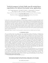
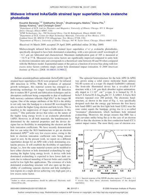
APPLIED PHYSICS LETTERS 94, 201107 2009<strong>Midwave</strong> <strong>infrared</strong> <strong>InAs</strong>/<strong>GaSb</strong> <strong>strained</strong> <strong>layer</strong> <strong>superlattice</strong> <strong>hole</strong> avalanchephotodiodeKoushik Banerjee, 1,a Siddhartha Ghosh, 1 Shubhrangshu Mallick, 2 Elena Plis, 3Sanjay Krishna, 3 and Christoph Grein 41 Department of ECE, Lab for Photonics and Magnetics, University of Illinois, Chicago, 851 S. MorganStreet, Chicago, Illinois 60607, USA2 EPIR Technologies, Inc., 590 Territorial Drive, Unit B, Bolingbrook, Illinois 60440, USA3 Department of ECE, Center for High Technology Materials, University of New Mexico, 1313,Goddard Street SE, MSC04 2710 Albuquerque, New Mexico 87106, USA4 Department of Physics, University of Illinois, Chicago, 845 W. Taylor Street, Chicago, Illinois 60607, USAReceived 16 March 2009; accepted 29 April 2009; published online 20 May 2009<strong>Midwave</strong>length <strong>infrared</strong> <strong>InAs</strong>–<strong>GaSb</strong> <strong>strained</strong> <strong>layer</strong> <strong>superlattice</strong> n + -n − -p avalanche photodiodes,specifically designed to have <strong>hole</strong> dominated avalanching, with a zero percent cutoff wavelength of6.3 m are fabricated and characterized. Maximum multiplication gain of 105 is measured at3.6 V at 77 K. Measured excess noise factors are significantly improved compared to unity <strong>hole</strong>to electron ionization ratio and corresponds to a theoretical value between 40 and 50 when comparedwith the McIntyre model. Exponential nature of the gain as a function of reverse bias along with lowexcess noise factors confirms single carrier <strong>hole</strong> dominated impact ionization. © 2009 AmericanInstitute of Physics. DOI: 10.1063/1.3139012Indium arsenide/gallium antimonide <strong>InAs</strong>/<strong>GaSb</strong> type-II<strong>strained</strong> <strong>layer</strong> <strong>superlattice</strong>s SLS were proposed 1 for <strong>infrared</strong>IR detection in 1970s. With the evolution of epitaxialgrowth techniques, this material system has emerged as apromising technology for longer wavelength IR detectiondue to mature III-V growth and fabrication techniques and itsabsorption coefficient being comparable to that of traditionalbulk mercury cadmium telluride HgCdTe 2 in the longer IRregime. One of the unique attributes of the SLS is the abilityto not only tune the bandgap to a desired IR wavelength butalso to tailor the higher lying electron and <strong>hole</strong> levels. This ismanifest in the suppression of Auger recombination in thissystem. 3,4 One particular device that relies on the nature ofthe higher lying energy levels is an avalanche photodiodeAPD. However, in all bulk materials, the bandstructure isdetermined by the material properties and the device designerhas no flexibility in manipulating the electron and the<strong>hole</strong> ionization coefficients. We have recently demonstratedthat we can tailor the SLS bandstructure to get an electrondominated APD 5,6 with very low excess noise, owing to the<strong>hole</strong> to electron ionization coefficient ratio being almostequal to zero. In the present work, we report on a different<strong>superlattice</strong> design for an APD with a <strong>hole</strong> dominating avalancheprocess. It will establish the flexibility of <strong>superlattice</strong>design, i.e., how the same material system can be modified tohave either electron or <strong>hole</strong> dominated avalanching by engineeringthe higher lying energy levels. A device with <strong>hole</strong>dominated avalanching is expected to have lower dark currentsdue to reduced tunneling of heavier <strong>hole</strong>s and could beuseful in low light flux applications. The existence of a <strong>hole</strong>dominated avalanching structure will also open up the possibilityof combining separate electron and <strong>hole</strong> multiplicationregions in a single device achieving very high gain yet alow excess noise factor.The epitaxial heterostructure for the <strong>hole</strong> APD h-APDwas grown using a solid source molecular beam epitaxyVG-80 system on a n-type Te doped <strong>GaSb</strong>001 substrate.The front-side illuminated device has a so-called N-I-Pstructure with a 1.44 m thick absorber region unintentionallydoped to 110 17 cm −3 p-type. It is formed by 35 Å<strong>InAs</strong>/3 Å GaAs/20 Å Ga 60 In 40 Sb/13 Å AlSb/1 Å GaAs SLSstructure repeated over 200 periods. The electronic bandstructure,as shown in the inset of Fig. 1, was specificallydesigned such that the energy gap between the first heavy<strong>hole</strong> band HH1 and the first light <strong>hole</strong> band LH1 near thezone center equals the bandgap, giving rise to a so-called“resonance” phenomenon, which facilitates <strong>hole</strong> initiatedavalanching. Moreover, the design ensures that HH1 has ahigh curvature unlike being flat as in the case of an electronAPD so that the electrons in the first conduction band CC1cannot impact ionize. The most likely case of electron avaaAuthor to whom correspondence should be addressed. Electronic mail:kbaner2@uic.edu.FIG. 1. Spectral response of the MWIR absorber region at 77 K under 1.1V reverse bias. Inset shows electronic bandstructure of the designed<strong>superlattice</strong>.0003-6951/2009/9420/201107/3/$25.0094, 201107-1© 2009 American Institute of PhysicsAuthor complimentary copy. Redistribution subject to AIP license or copyright, see http://apl.aip.org/apl/copyright.jsp
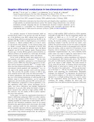
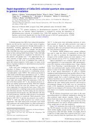
201107-2 Banerjee et al. Appl. Phys. Lett. 94, 201107 2009FIG. 2. Total current with illumination, dark-current, and correspondingmultiplication gain vs applied reverse bias at 77 K.lanching occurs when an electron from the second electronband CC2 drops to CC1. However, making the avalanchingregion lightly p-doped restricts the number of electrons inCC2 that can participate in the avalanching process. A moreelaborate discussion on the <strong>superlattice</strong> design and the devicestructure has been reported elsewhere. 7 Fourier transform <strong>infrared</strong>FTIR spectroscopy showed the absorption regionp − had a cutoff wavelength of 6.3 m at 77 K as illustratedin Fig. 1.Mesa structures were etched withH 2 O 2 :H 3 PO 4 :de-ionized water 2:1:20 etching solutionwith continuous agitation. 4400 Å ZnS was deposited as thepassivation <strong>layer</strong>. The passivation is critical especially insuch low bandgap materials because it minimizes the numberof surface states and hence reduces surface leakage currents.The performance of the passivant was optimized with a prepassivationtreatment of 20% warm 60 °C aqueous solutionof NH 4 2 S for 10 min. 8 200 Å Ti/200 Å Pt/4000 Å Auwas used as the contact and the pad metals. The junction areaof the devices had a diameter of 300 m.The fabricated devices were characterized using a JanisTechnology Inc. temperature and pressure controlled probestation with 300 K background. The temperature of the deviceswas varied from 77 to 200 K to study the change ingain characteristics at different temperatures. Current-voltagecharacteristics were measured with Agilent 4156B precisionsemiconductor parameter analyzer. A 632 nm He–Ne laserwith an incident power of 300 W was used to measure thephotocurrent and the gain of the APDs. For the gain calculation,the difference between the total currents with andwithout illumination at a particular bias was normalized withthe unity-gain photocurrent. The difference between the totalcurrents at zero bias was used as the reference for unity-gainphotocurrent. The excess noise of the APDs was measuredusing Agilent 8973B noise figure analyzer at a frequency of10 MHz with a bandwidth of 4 MHz.Figure 2 shows the typical breakdown characteristics ofan h-APD with a maximum multiplication gain of 105 at areverse bias voltage of 3.6 V at 77 K. The exponentialnature of the gain indicates single carrier dominated avalanchemechanism as seen in midwavelength IR MWIRHgCdTe APDs 9 or in electron dominated SLS APDs. 5,6 Themultiplication gain decreases with increasing temperatureand drops to unity at 200 K.FIG. 3. Excess noise factor vs multiplication gain characteristics. Symbolsindicate measured values with solid curves representing calculated excessnoise under the conventional local effect model for Ref. 10 with a fittedeffective k ratio, dashed line being the straight line fitted to the experimentaldata.McIntyre’s classical local-field model 10 suggests that theexcess noise factor F in an APD is a function of the multiplicationgain M and the relative ionization coefficient ofthe carriers k=/, where and are ionization coefficientsof the <strong>hole</strong>s and electrons respectively and for <strong>hole</strong>initiated avalanching is given byFM = M/k + 1−1/k2− 1 M.Figure 3 shows the excess noise factors measured for theh-APD. Though the F values are low for lower values ofmultiplication gain, it has a clear increasing trend as the multiplicationgain increases. Nevertheless, the values of the excessnoise factor are significantly lower if compared to thetheoretical values in case of unity ionization coefficient ratioas predicted by Eq. 1. The lower values confirm a <strong>hole</strong>dominated avalanching process since the device structure has<strong>hole</strong> initiated avalanching by design and electron dominationwould have resulted in very high values of the excess noisefactor. 10 A fitting of experimental data showed a linear trendof increment and was extended to higher values of multiplicationgain. Comparison with the values predicted by theMcIntyre model implies a value of k between 40 and 50.This value when compared to that k0 obtained in electronAPDs 6 illustrates the range of control that can beachieved through band engineering in the <strong>superlattice</strong> system.However, the present work is not a case of pure <strong>hole</strong>avalanching since pure <strong>hole</strong> avalanching k= suggests analmost constant value of excess noise factor even with increasinggain. The electrons participate in the avalanchingprocess at higher electric fields. This happens because theelectrons have a lower effective mass and under higher electricfields they can accelerate fast to gain enough energy toget promoted to the second conduction band and start avalanching.On the other hand, slight deviation of the actual<strong>superlattice</strong> structure from the ideal designed one breaks theresonance phenomenon in the band structure the energy gapbetween the first two <strong>hole</strong> bands near the zone center beingequal to the bandgap, thus disrupting the <strong>hole</strong> avalanchingprocess.Author complimentary copy. Redistribution subject to AIP license or copyright, see http://apl.aip.org/apl/copyright.jsp1
201107-3 Banerjee et al. Appl. Phys. Lett. 94, 201107 2009In conclusion, a low excess noise MWIR APD, usingtype-II <strong>superlattice</strong> as the absorber and multiplication region,was demonstrated to have <strong>hole</strong> dominated avalanching. Amaximum multiplication gain of 105 was achieved at a reversebias of 3.6 V at 77 K. The gain drops to unity at200 K. Effective ionization coefficient k was found to havea value between 40 and 50. The results establish the flexibilitywith which the <strong>superlattice</strong> system can be manipulated torender unique band structures.1 G. Sai-Halasz, R. Tsu, and L. Esaki, Appl. Phys. Lett. 30, 651 1977.2 D. L. Smith and C. Mailhiot, J. Appl. Phys. 62, 2545 1987.3 C. H. Grein, P. M. Young, and H. Ehrenreich, Appl. Phys. Lett. 61, 29051992.4 E. R. Youngdale, J. R. Meyer, C. A. Hoffman, F. J. Bartoli, C. H. Grein, P.M. Young, H. Ehrenreich, R. H. Miles, and D. H. Chow, Appl. Phys. Lett.64, 3160 1994.5 S. Mallick, K. Banerjee, S. Ghosh, J.-B. Rodriguez, and S. Krishna, IEEEPhotonics Technol. Lett. 19, 1843 2007.6 S. Mallick, K. Banerjee, J. B. Rodriguez, S. Krishna, and S. Ghosh, Appl.Phys. Lett. 91, 241111 2007.7 K. Banerjee, S. Mallick, S. Ghosh, E. Plis, J. B. Rodriguez, S. Krishna,and C. Grein, Mater. Res. Soc. Symp. Proc. 1076, 127 2008.8 S. Mallick, K. Banerjee, S. Ghosh, J. B. Rodriguez, and S. Krishna, IEEELEOS Annual Meeting, 2007 unpublished.9 M. A. Kinch, J. D. Beck, C.-F. Wan, F. Ma, and J. Campbell, J. Electron.Mater. 33, 630 2004.10 R. J. McIntyre, IEEE Trans. Electron Devices 13, 164 1966.Author complimentary copy. Redistribution subject to AIP license or copyright, see http://apl.aip.org/apl/copyright.jsp