Florham Park, New Jersey 07932 - Faraday
Florham Park, New Jersey 07932 - Faraday
Florham Park, New Jersey 07932 - Faraday

Create successful ePaper yourself
Turn your PDF publications into a flip-book with our unique Google optimized e-Paper software.
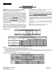
INSTALLATION INSTRUCTIONSMH MINI HORNSIMPORTANT – All audible and visual signaling appliances must beinstalled in accordance with all applicable national and local fire alarmcodes and any other required regulatory agency.Electronic MH Mini Horns are designed to produce high sound outputwith minimal current requirements. They are UL Listed under UL 464,Standard for Audible Signal Appliances and ULC Listed underStandard CAN/ULC-S525-99, Standard for Audible Signal AppliancesFor Fire Alarm Systems. All inputs are polarized for compatibility withstandard reverse polarity supervision of circuit wiring by a Fire AlarmControl Panel (FACP). MH Mini Horns are recommended for alarmsignaling for individual rooms in apartments, motels, hotels and offices.These appliances are attractive in appearance and reliable performers.They mount to standard backboxes to reduce the cost of installation.All models are Listed for indoor use with the backboxes specified inthese instructions (See Mounting Options).They provide a selectable Continuous or Code 3 horn tone whenconnected directly to an unsynchronized Fire Alarm Control Panel(FACP). They can also provide a synchronized Code 3 horn tonewhen connected to a notification appliance circuit running the Siemenssync protocol.MH Mini Horns can be used on coded systems where the appliedvoltage is cycled on and off.SPECIFICATIONS:Table 1: UL and ULC Listed Models and RangesModels Operating Voltage (Special Application) Voltage Range PerPer UL 464CAN/ULC-S525-99(VDC/VRMS)(VDC/VRMS)MH* 16.0-33.0 20.0-31.0* Units available in red and whiteTable 2: UL/ULC dBA Sound OutputDescription Reverberant Per UL 464 @ 10 Ft. Anechoic dBA Per CAN/ULC-S525-9916.0VDC 24.0VDC 33.0VDC 20.0VDC 24.0VDC 31.0VDCContinuous Horn 79 83 85 84 87 90Code 3 Horn 75 78 81 84 87 89Table 3: UL Current Ratings (AMPS)Maximum RMS CurrentDC 16.0-33.0VDC 0.026FWR 16.0-33.0VRMS 0.043Table 3A: ULC Current Ratings (AMPS)Rated Average Current20.0VDC .02424.0VDC .02531.0VDC .02620.0VRMS .02724.0VRMS .03831.0VRMS .043WARNING: FOR UL APPLICATIONS THESE APPLIANCES WERE TESTED TO THE OPERATING VOLTAGE LIMITS OF 16.0-33.0 VOLTSFOR 24.0VDC MODELS USING FILTERED (DC) OR UNFILTERED FULL-WAVE-RECTIFIED (FWR). DO NOT APPLY 80% AND 110% OF THESEVOLTAGE VALUES FOR SYSTEM OPERATION.WARNING: FOR ULC APPLICATIONS THESE APPLIANCES WERE TESTED TO THE OPERATING VOLTAGE LIMITS OF 20.0-31.0 VOLTSFOR 24VDC MODELS USING FILTERED (DC) OR UNFILTERED FULL-WAVE-RECTIFIED (FWR). APPLY 80% AND 110% OF THESE VOLTAGEVALUES FOR SYSTEM OPERATION.NOTE: 1. Anechoic dBA is measured in anechoic chamber with fast meter response. 2. Reverberant dBA is rated per UL 464, Standard for AudibleSignal Appliances. 3. As per ULC requirement, the -3dB off-axis is 15° and the -6dB off-axis is 30°.NOTE: MAKE SURE THAT THE TOTAL RMS CURRENT REQUIRED BY ALL APPLIANCES THAT ARE CONNECTED TO THE SYSTEM’SPRIMARY AND SECONDARY POWER SOURCES DO NOT EXCEED THE POWER SOURCES’ RATED CAPACITY OR THE CURRENT RATINGSOF ANY FUSES ON THE CIRCUITS TO WHICH THESE APPLIANCES ARE WIRED. OVERLOADING POWER SOURCES OR EXCEEDING FUSERATINGS COULD RESULT IN LOSS OF POWER AND FAILURE TO ALERT OCCUPANTS DURING AN EMERGENCY, WHICH COULD RESULT INPROPERTY DAMAGE AND SERIOUS INJURY OR DEATH TO YOU AND/OR OTHERSWhen calculating the total current: use Table 1 to determine the highest value of “Rated Average Current” for an individual horn (across the expectedoperating voltage range of the device); then multiply this value by the total number of devices; be sure to add the current for any other devices poweredby the same source and include any required safety factors.Siemens Building Technologies, Inc.P84408-003 B8 Fernwood Road Sheet 1 of 3<strong>Florham</strong> <strong>Park</strong>, <strong>New</strong> <strong>Jersey</strong> <strong>07932</strong>
Refer to P/N 315-096363 for the maximum number of notification appliances on a single appliance circuit.WIRING INFORMATION:FROM PRECEDING -APPLIANCE OR FIRE ALARM +CONTROL PANEL (FACP)Figure 1: Figure 2:- TO NEXT APPLIANCE+ OR END OF LINERESISTOR (EOLR)APPLIANCE1. Appliances have in-out wiring terminals that accept two #12 to #18 American Wire Gauge (AWG) wires at each screw terminal. Strip leads 3/8inches and connect to screw terminals.2. Break all in-out wire runs on supervised circuits to assure integrity of circuit supervision shown in Figure 2. The polarity shown in the wiringdiagrams is for the operation of the appliances. The polarity is reversed by the FACP during supervision.TEMPORAL (CODE 3) / NON-TEMPORAL (CONTINUOUS) JUMPER SETTINGS:Table 2: Jumper SettingsFACP NAC MH ResultContinuous Continuous ContinuousContinuous Temporal Code 3Code 3 Protocol Continuous Code 3Continuous with Sync Protocol * Temporal Synchronized Code 3* Requires the use of a synchronized Siemens Notification Appliance Circuit.Figure 3: Temporal (Code 3) / Non-Temporal (Continuous) SelectPINSLABELBEAUTYPLUGSTEMPORALNON-TEMPORALTERMINALSNOTE: Temporal (shorted) Non-Temporal (open)Unit is shipped from factory with Temporal (Code 3) selected (jumper to right). Installer can select Non-Temporal (Continuous) audible signal by movingthe factory installed jumper to the left one position. The jumper will be placed only on the left pin, leaving the circuit open to select Continuous. Detach‘Beauty Plugs’ from rear of grille before installing unit.Figure 4: Figure 5:3/8"ROUTE WIRETHROUGHNOTCH ASSHOWNSiemens Building Technologies, Inc.P84408-003 BSheet 2 of 3
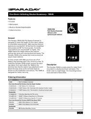
MOUNTING PROCEDURES:Use this mounting procedure to position the field wires in the backbox so that they use minimum space and produce minimum stress on the product.This is especially important for stiff, heavy gauge wires and wires with thick insulation or sheathing.1. Bend the 4 field wires 90° as shown in Figure 4.2. Connect the 2 field wires to each screw terminal (in-out wiring) and dress the 2 wires through the slot as shown in Figure 5 (polarity must beobserved).3. Gently push the 4 field wires into the backbox by hand and screw the unit to the backbox.MOUNTING OPTIONS:CAUTION: The following figures show the maximum number of field wires (conductors) that can enter the backbox used with each mounting option.If these limits are exceeded, there may be insufficient space in the backbox to accommodate the field wires and stresses from the wires could damagethe product.Although the limits shown for each mounting option comply with the National Electrical Code (NEC), Siemens Building Technologies recommends use ofthe largest backbox option shown and the use of approved stranded field wires, whenever possible, to provide additional wiring room for easy installationand minimum stress on the product from wiring.AFLUSH MOUNTINGBSURFACE MOUNTINGSINGLE-GANG X 3-1/2"DEEP BACKBOXSINGLE-GANG X 1-3/4"DEEP WIREMOLDBACKBOXMAXIMUM NUMBER OF CONDUCTORSAWG #18 AWG #16 AWG #14 AWG #124 4 4 4MAXIMUM NUMBER OF CONDUCTORSAWG #18 AWG #16 AWG #14 AWG #124 4 4 4MOUNTING NOTES:CAUTION: Check that the installed product will have sufficient clearance and wiring room prior to installing backboxes and conduit, especially ifsheathed multiconductor cable or 3/4" conduit fittings are used.1. Mounting hardware for each mounting option is supplied.2. When terminating field wires, do not use more lead length than required. Excess lead length could result in insufficient wiring space for thesignaling appliance.3. Use care and proper techniques to position the field wires in the backbox so that they use minimum space and produce minimum stress on theproduct. This is especially important for stiff, heavy gauge wires and wires with thick insulation or sheathing.4. Do not pass additional wires (used for other than the signaling appliance) through the backbox. Such additional wires could result in insufficientwiring space for the signaling appliance.5. Place ‘Beauty Plugs’ over screw heads after installation using the mounting hardware supplied.6. All models are UL Listed for indoor use with a temperature range of +32°F to +120°F (0°C to +49°C) and maximum humidity of 93% RH, ±2%.If this appliance is required to produce a distinctive three-pulse Temporal Pattern Fire Alarm Evacuation Signal (for total evacuation) in accordance withNFPA 72, 1999 Edition, the appliance must be used with a Siemens Fire Alarm Control unit that can generate the temporal pattern signal.Siemens Building Technologies, Inc.P84408-003 BSheet 3 of 3