installation instructions and wiring for p/n 8715 ... - Faraday
installation instructions and wiring for p/n 8715 ... - Faraday
installation instructions and wiring for p/n 8715 ... - Faraday

Create successful ePaper yourself
Turn your PDF publications into a flip-book with our unique Google optimized e-Paper software.
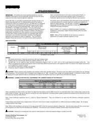
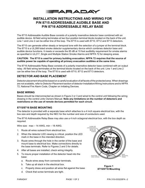
INSTALLATION INSTRUCTIONS AND WIRING FORP/N <strong>8715</strong> ADDRESSABLE AUDIBLE BASE ANDP/N 8716 ADDRESSABLE RELAY BASEThe <strong>8715</strong> Addressable Audible Base consists of a polarity insensitive detector base combined with anaudible device. All field <strong>wiring</strong> terminates at two four-position terminal blocks located on the back of the unit.Line 1 <strong>and</strong> Line 2 can be either line of the loop. The <strong>8715</strong> is used with 8710, 8712 <strong>and</strong> 8713 detectors.The <strong>8715</strong> can generate either steady or temporal tone with the selection of a jumper at the terminal block.The <strong>8715</strong> is a UL268 listed smoke detector supplementary device which combines detector base <strong>and</strong>audible device functions. It meets or exceeds the 85 dB at 10 foot audibility requirement <strong>for</strong> smoke alarmsas specified in UL217, Single <strong>and</strong> Multiple Station Smoke Alarms <strong>and</strong> NFPA 72 <strong>for</strong> sleeping areas.CAUTION: The <strong>8715</strong> is used <strong>for</strong> primary building evacuation; NFPA 72 requires that the source ofaudible power be capable of operating all primary evacuation audibles at the same time.The 8716 Addressable Relay Base consists of a polarity insensitive detector base combined with an outputrelay. All field <strong>wiring</strong> terminates at the terminal blocks located on the back of the unit. Line 1 <strong>and</strong> Line 2can be either line of the loop. The 8716 is used with 8710, 8712 <strong>and</strong> 8713 detectors.DETECTOR AND BASE PLACEMENTDetector placement should be based on a careful evaluation of all facets of the protected area. When drawingsare not available, refer to Detector Placement section of detector Installation/Wiring Instructions <strong>and</strong> to NFPA72, National Fire Alarm Code, Chapter on Initiating Devices.BASE WIRINGBases should be interconnected as shown in Figure 2 or 3 <strong>and</strong> wired to the control unit following the <strong>wiring</strong>drawing in the control units Owners Manual. Note any limitations on the number of detectors <strong>and</strong>restrictions on the use of remote devices permitted <strong>for</strong> each circuit.<strong>8715</strong>/8716 BASE MOUNTINGThe detector is provided with a separate base which attaches to a 4 inch square electrical box, with thebox size <strong>and</strong> depth required by the NEC <strong>for</strong> the number <strong>and</strong> size of conductors used.The 8716 Addressable Relay Base may also use a 4 inch octagonal electrical box, with the box depth asrequired.Wire size: max – 14 AWG, min – 18 AWG.1. Route all wires outward from electrical box.2. When the detector LED viewing is critical, position the LEDmark in the base in the intended direction.3. Route wires through the hole in the center of the base <strong>and</strong>mount base to electrical box. Make connections directly tothe base terminals. Refer to Figures 2 <strong>and</strong> 3 <strong>for</strong> details.4. After all bases are installed, check <strong>wiring</strong> integrity.5. To insure proper <strong>installation</strong> of the detector head into thebase:a. Route wires away from connector terminals.b. Take up all slack in the electrical box.c. Properly dress <strong>and</strong> position all wires flat against the base.d. Check that screw terminals are tight.ALARM LEDLOCATION WITHDETECTORINSTALLEDIN BASEMOUNTINGHOLE COVERSDO NOT PAINT651a1bFigure 1<strong>8715</strong>/8716 MountingBASEMOUNTINGHOLESFARADAYPAGE 1 OF 2P/N 315-033220FA -2
<strong>8715</strong> ADDRESSABLE AUDIBLE BASETO NEXTADDRESSABLEDEVICELINE 1 LINE 2TO NEXT <strong>8715</strong> OR PROPEREND OF LINE RESISTOR(SEE NAC INSTALLATIONINSTRUCTIONS)5678<strong>8715</strong>4321JUMPER FORTONE SELECTIONLINE 1 LINE 2FROM ADDRESSABLE DEVICE CIRCUITOF A COMPATIBLE CONTROL UNIT ORPREVIOUS ADDRESSABLE DEVICENOTES:1. For temporal tone, jumper terminals 3 <strong>and</strong> 4 as shown.For steady tone, do not jumper terminals 3 <strong>and</strong> 4.2. Audible Base electrical ratings:Alarm voltage range: 17-31VDCSupervisory current: 0mAAlarm current:24mA @ 25VDC3. T-tapping of notification appliance circuits is not allowed.FROM NOTIFICATION APPLIANCE CIRCUITOF A COMPATIBLE CONTROL UNIT OR8706 ADDRESSABLE NAC MODULE(POLARITY SHOWN IN ALARM)+4. Terminals 5-8 of the <strong>8715</strong> are polarity insensitive. Line 1<strong>and</strong> Line 2 can be either line of the loop.5. The <strong>8715</strong> shown can be wired as Style Z (Class A) orStyle Y (Class B). Refer to the <strong>installation</strong> <strong>instructions</strong> <strong>for</strong>the addressable device circuit <strong>and</strong> NAC circuit asapplicable.6. Polarity shown in alarm at terminals 1 <strong>and</strong> 2 of the <strong>8715</strong>.Each audible base must be tested to verify operation._Figure 2<strong>8715</strong> Wiring8716 ADDRESSABLE RELAY BASELINE 1LINE 1TO NEXT DEVICEDO NOT USE AN ENDOF LINE DEVICEFROM ADDRESSABLE DEVICECIRCUIT OF A COMPATIBLECONTROL UNIT OR PREVIOUSADDRESSABLE DEVICE87165NOC6NCRELAY CONTACTS3A, 120 VAC3A, 30 VDCRESISTIVELINE 2NOTE: RELAY CONTACTS ARE SHOWN IN THE SYSTEM NORMAL CONDITION.LINE 1 AND LINE 2 CAN BE EITHER LINE OF THE LOOP.LINE 2TO NEXT DEVICEDO NOT USE AN ENDOF LINE DEVICEFigure 38716 WiringPAGE 2 OF 2P/N 315-033220FA -2