
Create successful ePaper yourself
Turn your PDF publications into a flip-book with our unique Google optimized e-Paper software.
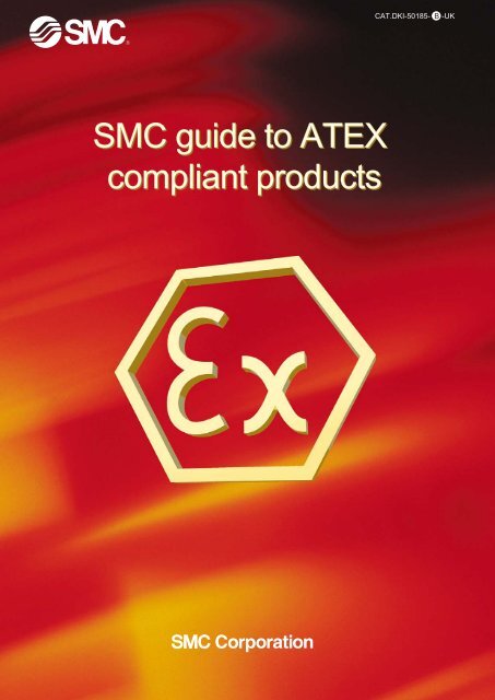
CAT.DKI-50185- B -UK<strong>SMC</strong> guide to <strong>ATEX</strong><strong>compliant</strong> products
<strong>SMC</strong> - provide productOutline of <strong>ATEX</strong> directiveSince 1st July 2003, equipment used in potentially explosive atmospheres withinthe EU is required to comply with the <strong>ATEX</strong> directive.<strong>ATEX</strong> directiveDirective 94/9/ECEquipment and Protective Systems intended for use in potentially Explosive Atmospheres<strong>ATEX</strong>, New Approach directives and CE markingDirective 94/9/EC, known as <strong>ATEX</strong> directive, is one of the directives based on the New Approach towards technical harmonization and standardisation.The New Approach is a new regulatory technique and strategy laid down by the European Council Resolution of 1985, in order to allow free movement ofgoods within the EU market and to prevent barriers to trade.Products in compliance with all provisions of applicable directives (such as Directive 94/9/EC for <strong>ATEX</strong>) must bear the CE marking. This is an indication thatthe products comply with the requirements of applicable directives and have been subjected to the conformity assessment procedure provided for in thesedirectives.<strong>ATEX</strong> definitionsPotentially explosive atmospheres are atmospheres likely to become explosive due to local and operational conditions.The <strong>ATEX</strong> directive regards explosive atmospheres which are defined as mixtures with air, under atmospheric conditions, of flammable substances in theform of gases, vapours, mists or dusts in which, after ignition has occurred, combustion spreads to the entire unburned mixture. (Quotation from Directive94/9/EC)The following applications are explicitly excluded by the <strong>ATEX</strong> directive and must comply with other specific standards: medical devices, equipment or safetydevices to be used with explosive or chemically unstable substances, equipment for domestic and non-commercial environments with explosive atmospheregenerated by leakage of fuel gas, personal protective equipment, offshore vessels, mobile units and means of transport.Certified equipment is designed to prevent the generation of ignition sources as defined by the standard EN1127-1:• hot surfaces• flames and hot gases• mechanically generated sparks• electrical sparks• stray electric currents, cathodiccorrosion protection• static electricity• lightning• electromagnetic fields• electromagnetic radiations• ionising radiations• ultrasonics• adiabatic compression shockwaves, gas flows• chemical reactionsZone 0Category 1Zone 2Category 3Zone 1Category 2ClassificationPotentially explosive environments areclassified into zones in accordance withDirective 1999/92/EC. These are:• 0, 1, 2 for gas explosive atmospheres• 20, 21, 22 for dust explosive atmospheres2The <strong>ATEX</strong> directive defines categories of equipment and protectivesystems, which can be used in the corresponding zones as per thefollowing table.ZoneGas Dust012202122Equipmentcategory123Presence of the explosiveatmosphereContinuously or for long periods>1000 hours/yearOccasionally10~1000 hours/yearRarely or for short periods
s <strong>compliant</strong> to <strong>ATEX</strong> DirectiveNew elements at a glancePrevious legislation covered the most obvious sources of ignition generated by electrical devices.The <strong>ATEX</strong> directive and the corresponding harmonised standards have extended the applicability of legislation to all theequipment that is intended for generation, transfer, storage, measurement, control and conversion of energy.Pneumatic equipment used in potentially explosive atmospheres must, therefore, comply with the new legislation.Products, which do not contain any potential ignition sources, are out of the scope of the directive.<strong>ATEX</strong> label example and explanation<strong>SMC</strong> CORPORATION1-16-4,ShimbashiMinato-ku, Tokyo, Japan"Do not un-plug when energized"II 3 G / DGroupIICategory 1 23EEx nA II T6 XVQCxxxHOTamb =-10°C to +50°CIP65T 80°C<strong>ATEX</strong>complianceAtmosphere* G D G D G D*G=Gas D=DustCategoryStandardsforElectricalproductStandardsforNon-electricalproductGeneral requlrements all EN 50014 EN13463-1Part-numberYearOperating temperatureIP (only for Dust)T temperature(only for Dust)T1T2T3T4T5T6Max. Surfacetemperature450°C300°C200°C135°C100°C85°CDust protection all EN 50281-1-1Types of ProtectionEN13463-1Constructional safety "c" 2 EN13463-5Types of Protection "n" 3 EN50021Increased Safety "e"Encapsulation "m"Flameproof Enclosure "d"Oil lmmersion "o"Pressurized "p"Powder Filling "q"Intrinsically Safety "ia"Intrinsically Safety "ib"22222212EN50019EN50028EN50018EN50015EN50016EN50017EN50020EN50020EN13463-3EN13463-7X=means that special conditions for use are in theoperating manual. E.g.; Not impact proof.INDEXActuatorRotary ActuatorOthers55-C76 Air CylinderP. 0456-CRQ2 Rotary ActuatorP. 2356-PA3000/5000 Process PumpP. 7055-C85 Air CylinderP. 0655-CRB1 Rotary ActuatorP. 2456-VBA Booster RegulatorP. 7155-C95 Air CylinderP. 0855-CRB2 Rotary ActuatorP. 26Directional Valves55-CP95 Air CylinderP. 1055-CRBU2 Rotary ActuatorP. 2852-SY 5 Port Solenoid ValvesP. 7355-CG1 Air CylinderP. 1255-C(D)RQ2 Rotary ActuatorP. 3056-SV 5 Port Solenoid ValvesP. 9455-CS1 Air CylinderP. 1456-C(D)RB1 Rotary ActuatorP. 3256-VQC 5 Port Solenoid ValvesP. 10655-(E)CQ2 Compact CylinderP. 1656-C(D)RB2 Rotary ActuatorP. 3456-VX21/22/23 2 Port ValvesP.12155-CXS Dual Rod CylinderP. 1856-C(D)RBU2 Rotary ActuatorP. 3656-EX250 Serial TransmissionP.13255-MY1B Mechanically Rodless CylinderP. 20Auto SwitchesP. 3856-EX500 Serial TransmissionP. 13355-MY1M Mechanically Rodless CylinderP. 21InstrumentsSafety Precautions55-MY1H Mechanically Rodless CylinderP. 22IP5000 Pneumatic PositionerP. 52Safety InstruictionsP.137IP6000-X14 Electro Pneumatic PositinerP. 53IP8000-X14 Electro Pneumatic PositinerP. 5652-IP8101 Smart PositinerP. 633
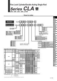
<strong>ATEX</strong> Compliant Air cylinder/ Double actingSeries 55-C76ø32, ø40How to order<strong>ATEX</strong> category 2Built-in magnetDNoneBuilt-in magnet55 - CD76E 3250 C ACushion-CAuto switch mounting typeABRail mountingBand mountingRubber bumperAir cushion (only "E" execution)Mounting styleEF∗Y∗Double end typeFront nose typeFront nose in line type∗ Except for air cushion type.Bore sizeBore size (mm)ø 32ø 40StrokeStandard stroke (mm)10, 25, 40, 50, 80, 100125, 160, 200, 250, 300Max. stroke (mm)1000Parts No. of Mounting BracketMounting bracketBore size (mm)32 40Flange, Foot (1pc.) C76F32A C76F40AFlange, Foot(2 pcs. with mountingMounting bracket nut 1 pc.)C76F32B C76F40BTrunnion C76T32 C76T40Clevis C76C32 C76C40Single knuckle joint KJ10DA KJ12DAAccessories Double knuckle joint GKM10-20A GKM12-24AFloating joint JA25-10-150 JA40-12-175For 55-CD76When using an Auto switch, select the appropriate switch from the following table and order it separately.Applicable auto switch specificationsAuto switch only conforms to Category 3. (II 3GD EEx nA II T5x -10°C ≤ Ta ≤ +60°C IP67)For detailed specifications on the D-A73(H), A80(H), F7P(V), C73, C80, and H7A2, please refer to the relevant pages in Best Pneumatics.(Note: Reed auto switches for AC 100V and DC 100V are not within the specification.)TypeReed D-A80-588auto switch D-A73H-588D-A80H-588Solid stateauto switchRail mountingD-A73-588D-F7PV-588D-F7P-588Model No.Band mountingElectrical entryIndicatorWiring(Output)Load voltageGrommet Yes24V 12V(Perpendicular entry) No24V or less2-wiring48V 48V or lessD-C73-588D-C80-588Grommet(In-line entry)YesNo24V24V or less12V48V 48V or lessGrommet(Perpendicular entry)Yes 3-wiring24V 5V, 12VGrommet (PNP)D-H7A2-588(In-line entry)• Lead wire length 0.5m --- Nil (e.g.) D-A73-5883 m --- L (e.g.) D-A73L-5885 m --- Z (e.g.) D-A73Z-588Note 2) When mounting an auto switch on a 55- series (Category 2) Model,the <strong>ATEX</strong> category of the auto switch cylinder changes to Category 3,which is the same category as the auto switch.4DCNote 1)AC0.5(—)Lead wire ∗ (m)3(L)5(Z)IC circuitIC circuitIC circuitApplicableloadRelayPLCsolid state auto switch is available after receiving an order.When ordering a band mounting type auto switch,also order a mounting bracket from the following listat the same time.Auto switch mounting bracket/ Part no. (Band mounting type)Auto switchModelD-C73-588D-C80-588D-H7A2-588Tube I.D. (mm)32 40BM2-032BM2-040
<strong>ATEX</strong> Compliant Air Cylinder Standard: Double Acting Series 55-C76SymbolStandard: double actionRubber CushionSingle rodSpecificationsBore size<strong>ATEX</strong> category 1)Piston rod. dia. (mm)Piston rod threadPortsActionFluidProof pressureMax. operating pressureMin. operating pressureAmbient and fluid temperatureLubricationOperating piston speedAllowable stroke toleranceCushionPort sizeMountingAllowablekineticenergy (J)Rubber cushionAir cushionø32ø4090°C (T5) Ta –10 to 40°CII 2GDc110°C (T4) Ta 40 to 60°C12 14M10x1.5 M12 x1.75G1/8 G1/4Double actingAir1.5MPa1.0MPa0.05MPa–10 to 60°C (No freezing)Not required (Non-lube)50 to 1000 mm/s0/+1.4Rubber bumper, Air cushionG1/8 G1/4Double end, Front nose, Front nose in line0,651.21,072.35Air CushionSingle rodNote 1) This cylinder can be used in zones 1 and 21 and in zones 2 and 22.If the cylinder is used with <strong>SMC</strong> category 3 type auto switch, then thecylinder can only be used in zones 2 and 22 and not in zones1 and 21.Note) All other specifications(dimensions, drawings, etc.)are the same as the non <strong>ATEX</strong> type.5
TypeReed D-A80-588auto switch D-A73H-588D-A80H-588Solid stateauto switchMounting Bracket Part No.Bore (mm)BracketFoot (1 pc.)Foot (2 pcs. withmounting nut 1 pc.)FlangeTrunnionClevisSingle knuckle jointDouble knuckle jointFloating joint—DStyleStandardNon rotating rod(only rubber bumper)Mounting styleSymbol MountingN Basic integrated clevisE ∗∗∗ Double end typeF∗∗Front nose typeY∗∗Front nose in line type∗ Double acting/Double rod type:Only double end type (E).∗∗ Except for air cushion type8 10 12 16 20 25C85L10AC85L10BC85F10C85T10C85C10KJ4DGKM4-8JA10-4-070C85L16AC85L16BC85F16C85T16C85C16KJ6DGKM6-10JA15-6-100Note) Please order mounting brackets separately.IndicatorHow to OrderC85L25AC85L25BC85F25C85T25C85C25KJ8D KJ10DGKM8-16 GKM10-20JA20 JA30-8-125 -10-125Bore size StrokeBore size (mm)ø8 ∗ø10ø12ø16ø20ø25Cushion— Rubber bumper (Standard)Air cushion (only "N" execution,Cbores 10 to 25mm)Standard stroke (mm) ∗∗10, 25, 40, 50, 80, 10010, 25, 40, 50, 80, 100,125, 160, 20010, 25, 40, 50, 80, 100,125, 160, 200, 250, 300∗ Not available with air cushion.∗∗ Other strokes available on request.For 55-CD85When using an Auto switch, select the appropriate switch from the following table and order it separately.Applicable auto switch specificationsAuto switch only conforms to Category 3. (II 3GD EEx nA II T5x -10°C ≤ Ta ≤ +60°C IP67)For detailed specifications on the D-A73(H), A80(H), F7P(V), C73, C80, and H7A2, please refer to the relevant pages in Best Pneumatics.(Note: Reed auto switches for AC 100V and DC 100V are not within the specification.)Load voltageModel No.Electrical entryWiring(Output) DC ACRail mounting Band mountingD-A73-588Grommet Yes24V 12V(Perpendicular entry) No24V or less2-wiring48V 48V or lessD-C73-588 Grommet Yes24V 12VD-C80-588 (In-line entry) No24V or less 48V 48V or lessD-F7PV-588Grommet(Perpendicular entry)Yes 3-wiringD-F7P-588 D-H7A2-588Grommet (PNP)(In-line entry)24V 5V, 12V• Lead wire length 0.5m --- Nil (e.g.) D-A73-5883 m --- L (e.g.) D-A73L-5885 m --- Z (e.g.) D-A73Z-588Note 2) When mounting an auto switch on a 55- series (Category 2) Model,the <strong>ATEX</strong> category of the auto switch cylinder changes to Category 3,which is the same category as the auto switch.6Double actingSingle rod 55-C D 85 K N 20 40 C ADouble rod 55-C D 85WE 20 40 C BDouble acting<strong>ATEX</strong> Compliant ISO Cylinder/Standard: Double ActingSeries 55-C85ø8, ø10, ø12, ø16, ø20, ø25<strong>ATEX</strong> category 2Magnet— NoneD Built-in magnetNote 1)0.5(—)Lead wire ∗ (m)3(L)Max. stroke (mm)40010005(Z)IC circuitIC circuitIC circuitApplicableloadRelayPLCsolid state auto switch is available after receiving an order.When ordering a band mounting type auto switch,also order a mounting bracket from the following listat the same time.Auto switch mounting bracket/ Part no. (Band mounting type)Auto switchModelD-C73-588D-C80-588D-H7A2-5888 10Auto switch mounting typeA Rail mountingB Band mounting1002001000Tube I.D. (mm)12 16 201002001000BJ2-008 BJ2-010 BJ2-012 BJ2-016 BM2-020 BM2-02525
<strong>ATEX</strong> Compliant ISO Cylinder/Standard: Double Acting Series 55-C85Air Cushion/Single RodRubber Bumper/Single RodSpecificationsBore size (mm)<strong>ATEX</strong> category 1)Piston rod dia. (mm)Piston rod threadPortsActionFluidProof pressureMax. operating pressure8 10 12 16 20 2590°C (T5) Ta –10 to 40°CII 2GDc110°C (T4) Ta 40 to 60°C4 4 6 6 8 10M4 X 0.7 M4 X 0.7 M6 X 1 M6 X 1 M8 X 1.25 M10 X 1.25M5 M5 M5 M5 G1/8 G1/8Double actingAir1.5MPa1.0MPaMin. operating pressure0.1MPa0.08MPa0.05MPaSymbolDouble Acting/Single RodAmbient and fluidtemperatureCushionLubricationPiston speed–10 to 60°C (no freezing)Rubber bumper, Air cushion (Except for ø8)Not required. If necessary turbine oil no.1 ISOVG32 is recommended50 to 1000mm/sRubber BumperAir CushionNote) All other specifications(dimensions, drawings, etc.)are the same as the non <strong>ATEX</strong> type.AllowablekineticenergyRubberbumperAircushionNon-rotating accuracyStroke tolerance0.02J 0.03J 0.04J 0.09J 0.27J 0.4J— 0.17J 0.19J 0.4J 0.64J 0.93J±1° 30' ±1° 30' ±1° ±1° ±0° 42' ±0° 42'0/+1 0/+1.4Note 1) This cylinder can be used in zones 1 and 21 and in zones 2 and 22.If the cylinder is used with <strong>SMC</strong> category 3 type auto switch, then thecylinder can only be used in zones 2 and 22 and not in zones1 and 21.7
<strong>ATEX</strong> <strong>compliant</strong> ISO Cylinder: Double ActingSeries 55-C95ø32, ø40, ø50, ø63, ø80, ø100, ø125, ø160, ø200, ø250<strong>ATEX</strong> category 2How to Order55-C95SD B 32 100 WXC6ExecutionStandard TypeWith MountingCentre TrunnionNon-rotatingpiston rodBuilt-in magnet-DModel SelectionNoneBuilt-in magnetModel55-C95 SB55-C95 SDB55-C95 ST55-C95 SDT55-C95 KB55-C95 KDBBLFGCDTMountingBasic/Without bracketAxial footFront flangeRear flangeSingle rear clevisDouble rear clevisCentre trunnionBore size3240506380100125160200250Bore size32mm40mm50mm63mm80mm100mm125mm160mm200mm250mm32 40 50 63 80 100 125 160 200 250Rod Specifications- Hard chromed rod as standardW Note) Double rodNote) Double rod is not available for bore size diameter125, 160, 200, 250 mm.Stroke (mm)Refer to standard stroke tableAdjustableStroke EndCushioningPiston RodOptionsStandardHard ChromeWW = Double RodOptionsStandardNote1) 55-C95 can be used in zones 1 and 21 and in zones 2 and 22.Note2) If the 55-C95 cylinder is used with <strong>SMC</strong> category 3 type auto switch, then the 55-C95 cylinder can only be used in zones 2 and 22 and not zones 1 and 21.Note3) Piston rod material is stainless steel.For 55-C95When using an Auto switch, select the appropriate switch from the following table and order it separately.Applicable auto switch specificationsAuto switch only conforms to Category 3. (II 3GD EEx nA II T5x -10°C ≤ Ta ≤ +60°C IP67)For detailed specifications on the D-A54, A67, and F5P, please refer to the relevant pages in Best Pneumatics.(Note: Reed auto switches for AC 100V and DC 100V are not within the specification.)TypeReedauto switchSolid stateauto switch• Lead wire lengthPiston rod typeSKModel No.D-A54-588D-A67-588D-F5P-588StandardNon-rotating rod (32~100 only)Electrical entryGrommetGrommet0.5m --- Nil (e.g.) D-A54-5883 m --- L (e.g.) D-A54L-5885 m --- Z (e.g.) D-A54Z-588IndicatorYesNoYesWiring(Output)2-wiring3-wiring(PNP)Note 2) When mounting an auto switch on a 55- series (Category 2) Model,the <strong>ATEX</strong> category of the auto switch cylinder changes to Category 3,which is the same category as the auto switch.24VDCLoad voltage12V24V or less24V5V,12VNote 1)AC0.5(—)Lead wire ∗ (m)3(L)5(Z)IC circuitIC circuitApplicableloadRelayPLCsolid state auto switch is available after receiving an order.When ordering a tie rod mounting type auto switch,also order a mounting bracket from the following listat the same time.Auto switch mounting bracket/ Part no. (Tie rod mounting)Auto switchModelD-A54-588D-A67-588D-F5P-58832,40 50,63BT-03BT-05Note 3Note 3Tube I.D. (mm)80,100 125BT-06Special-XC6BT-08StandardStainless steel rod and nut160BT-16200BT-16250BT-208
Series 55-C95ISO SymbolDouble actingSpecificationsBore size<strong>ATEX</strong> categoryActionFluidProof pressureMax. operating pressureMin. operating pressureAmbient and fluid temperatureLubricationOperating piston speedAllowable stroke toleranceCushionThread tolerancePort sizeMountingø32 ø40 ø50 ø63 ø80 ø100ø125 ø160 ø200 ø25095°C (T5) Ta –10 to 40°CII 2GDc115°C (T4) Ta 40 to 60°CDouble actingAir1.5MPa1.0MPa0.05MPa–10 to 60°C (No freezing)Not required (Non-lube)5050 to 1000 mm/s to 700 50 to 500 mm/smm/sto 250: +1.0, 251 to 1000: +1.4,1001 to 1500: +1.8000Both ends (Air cushion)JIS class 2G1/8 G1/4 G1/4 G3/8 G3/8 G1/2 G1/2 G3/4 G3/4 G1Basic, axial foot, front flange, rear flange,single rear clevis, double rear clevis, centre trunnionNote) All other specifications(dimensions, drawings, etc.)are the same as the non <strong>ATEX</strong> type.Standard StrokeBore size(mm)Mounting Bracket, Mounting AccessoriesStandard stroke (mm)32 25, 50, 80, 100, 125, 160, 200, 250, 320, 400, 50040 25, 50, 80, 100, 125, 160, 200, 250, 320, 400, 50050 25, 50, 80, 100, 125, 160, 200, 250, 320, 400, 500, 60063 25, 50, 80, 100, 125, 160, 200, 250, 320, 400, 500, 60080 25, 50, 80, 100, 125, 160, 200, 250, 320, 400, 500, 600, 700, 800100 25, 50, 80, 100, 125, 160, 200, 250, 320, 400, 500, 600, 700, 800125 Each stroke will be made to order160 Each stroke will be made to order200 Each stroke will be made to order250 Each stroke will be made to order(*) Please consult <strong>SMC</strong> for longer stroke.(*) Max.stroke70080012001200140015001600160020002400DescriptionBore size ø32 ø40 ø50 ø63 ø80 ø100ø125 ø160 ø200ø250LF, GCDDSESEGKMKJJAFoot (1)FlangeSingle rear clevisDouble rear clevisDouble rear clevis(for ES accessory)Angled rear cleviswith ball jointAngled rear clevisRod clevisPiston rod ball jointFloating jointL5032F5032C5032D5032DS5032ES5032E5032GKM10-20KJ10DL5040F5040C5040D5040DS5040ES5040E5040GKM12-24KJ12DL5050F5050C5050D5050DS5050ES5050E5050GKM16-32KJ16DL5063F5063C5063D5063DS5063ES5063E5063GKM16-32KJ16DL5080F5080C5080D5080DS5080ES5080E5080GKM20-40KJ20DJA30-10-125 JA40-12-125 JA50-16-150 JA50-16-150 JAH50-20-150L5100F5100C5100D5100DS5100ES5100E5100GKM20-40KJ20DJAH50-20-150L5125F5125C5125D5125L5160 L5200F5160 F5200C5160 C5200D5160 D5200Note 6)L5250F5250C5250D5250Note 1) Two foot brackets required for one cylinder.Note 2) Accessories for each mounting bracket are as follows.Foot, Flange, Single clevis: Mounting boltsDouble rear clevis: (D,DS): Clevis pinNote 3) GKM according to ISO 8140Note 4) KJ according to ISO 8139Note 5) Piston rod nut is standard (Bore size 32 to 125)Note 6) Please consult <strong>SMC</strong>9
<strong>ATEX</strong> Compliant ISO Cylinder/Standard:Double ActingSeries 55-CP95ø32, ø40, ø50, ø63, ø80, ø100How to Order55-CP95SDB 32100 WPiston rod typeSKStandardNon-rotatingModel SelectionExecutionStandard TypeNon-rotatinpiston rod<strong>ATEX</strong> category 2BLFGCDBuilt-in magnet-DMountingBasic/Without bracketAxial footFront flangeRear flangeSingle rear clevisDouble rear clevisModel55-CP95 SB55-CP95 SDB55-CP95 KB55-CP95KDBNoneBuilt in magnet3240506380100Bore size32mm40mm50mm63mm80mm100mmRod Specifications-WStroke (mm)Refer to standard stroke tablefollowing pageAdjustableStroke EndCushioningPiston RodOptionsStandardHard ChromeNote 3)Note 3)Hard chromed rod as standardDouble rodWW = Double RodOptionsStandardNote1) 55-C95 can be used in zones 1 and 21 and in zones 2 and 22.Note2) If the 55-C95 cylinder is used with <strong>SMC</strong> category 3 type auto switch, then the 55-C95 cylinder can only be used in zones 2 and 22 and not zones 1 and 21.Note3) Piston rod material is stainless steel.For 55-CP95When using an Auto switch, select the appropriate switch from the following table and order it separately.Applicable auto switch specificationsAuto switch only conforms to Category 3. (II 3GD EEx nA II T5x -10°C ≤ Ta ≤ +60°C IP67)For detailed specifications on the D-Z73, Z80, Y7P, and Y7PV, please refer to the relevant pages in Best Pneumatics.(Note: Reed auto switches for AC 100V and DC 100V are not within the specification.)10TypeReedauto switchSolid stateauto switch• Lead wire lengthModel No.D-Z73-588D-Z80-588D-Y7P-588D-Y7PV-588Electrical entryGrommet(in-line)Grommet(in-line)Grommet(Perpendicular)0.5m --- Nil (e.g.) D-Z73-5883 m --- L (e.g.) D-Z73L-5885 m --- Z (e.g.) D-Z73Z-588IndicatorYesNoYesWiring(Output)2-wiring3-wiring(PNP)Note 2) When mounting an auto switch on a 55- series (Category 2) Model,the <strong>ATEX</strong> category of the auto switch cylinder changes to Category 3,which is the same category as the auto switch.24VDC24V or less24VLoad voltage12V48V5V,12VNote 1)AC0.5(—)Lead wire ∗ (m)3(L)5(Z)IC circuitIC circuitApplicableloadRelayPLCsolid state auto switch is available after receiving an order.When ordering a direct mounting type auto switch,also order a mounting bracket from the following listat the same time.Auto switch mounting bracket/ Part no. (Direct mounting type)Auto switchModelD-Z73-588D-Z80-588D-Y7P-588D-Y7PV-58848V or lessTube I.D. (mm)32,40,50,63,80,100BMP1-032
Series 55-CP95ISO SymbolDouble actingNote) All other specifications(dimensions, drawings, etc.)are the same as the non <strong>ATEX</strong> type.SpecificationsBore size<strong>ATEX</strong> category 1)ActionFluidProof pressureMax. operating pressureMin. operating pressureLubricationAmbient and fluid temperatureOperating piston speedAllowable stroke toleranceCushionThread tolerancePort sizeMountingStandard StrokeBore size(mm)ø32 ø40 ø50 ø63 ø80 ø100Double actingAir (Non-lube)1.5MPa1.0MPa0.05MPaNot required (Non-lube)–10 to 60°C50 to 1000mm/s+1.0+1.4to 250: 0 , 251 to 1000: 0Both ends (Air cushion)JIS class 2G1/8 G1/4 G1/4 G3/8 G3/8 G1/2Basic, axial foot, front flange, rear flange,single rear clevis, double rear clevisStandard stroke (mm)II 2GDcNote 1) This cylinder can be used in zones 1 and 21 and in zones 2 and 22.If the cylinder is used with <strong>SMC</strong> category 3 type auto switch, then thecylinder can only be used in zones 2 and 22 and not in zones1 and 21.32 25, 50, 80, 100, 125, 160, 200, 250, 320, 400, 50040 25, 50, 80, 100, 125, 160, 200, 250, 320, 400, 50050 25, 50, 80, 100, 125, 160, 200, 250, 320, 400, 500, 60063 25, 50, 80, 100, 125, 160, 200, 250, 320, 400, 500, 60080 25, 50, 80, 100, 125, 160, 200, 250, 320, 400, 500, 600, 700, 800100 25, 50, 80, 100, 125, 160, 200, 250, 320, 400, 500, 600, 700, 800Intermediate strokes are available.95°C (T5) Ta –10 to 40°C115°C (T4) Ta 40 to 60°CMax. ∗stroke7008001200120014001500Mounting Bracket, Mounting AccessoriesDescriptionLF, GCDDSESEGKMKJJABore size ø32 ø40 ø50 ø63 ø80 ø100Foot (1)FlangeSingle rear clevisDouble rear clevisDouble rear clevis(for ES accessory)Angled rear cleviswith ball jointAngled rear clevisRod clevisPiston rod ball jointFloating jointL5032F5032C5032D5032DS5032ES5032E5032GKM10-20KJ10DJA30-10-125L5040F5040C5040D5040DS5040ES5040E5040GKM12-24KJ12DJA40-12-125L5050F5050C5050D5050DS5050ES5050Note 1) Two foot brackets required for one cylinder.Note 2) Accessories for each mounting bracket are as follows.Foot, Flange, Single clevis: Mounting boltsDouble rear clevis: (D,DS): Clevis pinNote 3) GKM according to ISO 8140Note 4) KJ according to ISO 8139Note 5) Piston rod nut is standardL5063F5063C5063D5063DS5063ES5063E5050 E5063GKM16-32 GKM16-32KJ16D KJ16DJA50-16-150 JA50-16-150L5080F5080C5080D5080DS5080ES5080L5100F5100C5100D5100DS5100ES5100E5080 E5100GKM20-40 GKM20-40KJ20D KJ20DJAH50-20-150 JAH50-20-15011
<strong>ATEX</strong> Compliant Air cylinder/ Double actingSeries 55-CG1ø20, ø25, ø32, ø40, ø50, ø63, ø80, ø100How to OrderStandard55 -CG1L N 25With auto switch55 - CDG1LN 25<strong>ATEX</strong> category 2With auto switch(magnet)MountingB BasicL Axial footF Front flangeG Rear flangeU ∗ Front trunnionT ∗ Rear trunnionD Clevis∗ Not available for boresizes ø80 and ø100.∗∗ Mounting brackets areincluded, not mounted.NACushionRubber bumperAir cushionCylinder stroke (mm)Bore size(mm)Standard stroke (1)(mm)Long Maxstroke (2) stroke(mm) (mm)20 25, 50, 75, 100, 125, 150, 200 201 to 35025301 to 40032301 to 45040 25, 50, 75, 100, 125, 301 to 800 150050/63150, 200, 250, 300301 to 120080301 to 1400100301 to 1500Note 1) Other intermediate strokes can bemanufactured upon receipt of order.Spacers are not used for theintermediate strokes.Note 2) Long stroke applies to the axial footand the front flange style. If othermounting brackets are used or thelength exceeds the stroke limit,the stroke should be determinedbased on the stroke selection tablein the technical data.2025324020mm25mm32mm40mm506380100Bore size50mm63mm80mm100mmThread type of portRubber bumperNilTNTFRcNPTGø20~ø100ø20~ø100ø32~ø100Air cushionNilM5x0.8 ø20~ø25Rc ø32~ø100TNTFNPTGø32~ø100ø32~ø10012
Series 55-CG1Note) All other specifications(dimensions, drawings, etc.)are the same as the non <strong>ATEX</strong> type.SpecificationsBore size (mm)<strong>ATEX</strong> category 1)ActionLubricationFluidProof pressureMax. operating pressureMin. operating pressureAmbient and fluid temperaturePiston speedStroke toleranceCushion20 25 32 40 50 63 80 10090°C (T5) Ta –10 to 40°CII 2GDc110°C (T4) Ta 40 to 60°CDouble acting/Single rodNon-lubeAir1.5MPa1.0MPa0.05MPaWithout auto switch: –10 to +70°C (No freezing)With auto switch: –10 to +60°C (No freezing)50 to 1000mm/s50 to 700mm/s+1.4+1.4+1.8 Up to 1000 0 mmUp to 1000 0 mm, Up to 1200 0 mm+1.8Up to 1500 0 mmRubber bumper/Air cushionJIS symbolDouble actingMounting ∗Basic, Axial foot, Front flange, Rear flange, Front trunnion,Rear trunnion, Clevis(Used for changing the port location by 90° degrees.)∗ Front/Rear trunnion styles are not available for bore sizes ¯80 and ø100.Note 1) This cylinder can be used in zones 1 and 21 and in zones 2 and 22.If the cylinder is used with <strong>SMC</strong> category 3 type auto switch, then thecylinder can only be used in zones 2 and 22 and not in zones1 and 21.AccessoriesMountingRod end nutStandardClevis pinSingle knuckle jointDouble knucklejoint ∗∗Option (With pins)Pivot bracketRod bootBasic——Axialfoot∗ Pivot bracket is not available for bore sizes ø80 and ø100.∗∗ Pins and snap rings for double knuckle joint are included, not mounted.——Frontflange——Rearflange— — ——Fronttrunnion∗Reartrunnion∗ClevisMounting Bracket Part No.Mounting bracketBore size (mm)20 25 32 40 50Axial foot ∗ CG-L020 CG-L025 CG-L032 CG-L040 CG-L050FlangeCG-F020 CG-F025 CG-F032 CG-F040 CG-F050Trunnion CG-T020 CG-T025 CG-T032 CG-T040 CG-T050Clevis ∗∗ CG-D020 CG-D025 CG-D032 CG-D040 CG-D050Pivot bracket CG-020-24A CG-025-24A CG-032-24A CG-040-24A CG-050-24A∗ Order two foot brackets per a cylinder.∗∗ Clevis pins, snap rings and mounting bolts are attached for the clevis.∗∗∗ Mounting bolts are attached for the foot type and the flange type.6380100CG-L063CG-F063CG-T063CG-D063CG-L080CG-F080—CG-D080CG-L100CG-F100—CG-D100CG-063-24A CG-080-24A CG-100-24A13
<strong>ATEX</strong> Compliant Air Cylinder/StandardSeries 55-CS1Non-lube: ø125, ø140, ø160, ø180, ø200, ø250, ø300How to Order55-CDS1 L N 160 300R-DBLFGCDTMounting Bracket Part No.Bore size (mm) 125 140Foot ∗Flange<strong>ATEX</strong> category 2ø125~ø300ø125~ø200Single clevisDouble clevis ∗∗Build in magnetWithout magnetBuilt in magnet-WCS1-L12CS1-F12CS1-C12CS1-D12Rod typeSingle rodDouble rodMountingBasicFootFront flangeRear flangeSingle clevisDouble clevisCentre trunnionMounting optionsfor W type: B, L, F, TCS1-L14CS1-F14CS1-C14CS1-D14160CS1-L16CS1-F16CS1-C16CS1-D16180CS1-L18CS1-F18CS1-C18CS1-D18200CS1-L20CS1-F20CS1-C20CS1-D20Non-lube250CS1-L25CS1-F25CS1-C25CS1-D25∗ Order 2 foot brackets for one cylinder.∗∗ When ordering the double clevis, the clevis pin and the cotter pin (2 pcs.) are attached.300CS1-L30CS1-F30CS1-C30CS1-D30Rod boot/CushionN No cushionR With cushion on rod sideH With cushion on head sideCushion—Cylinder stroke (mm)(Refer to following page for max. stroke table.)Tube materialSymbol Bore size Tube materialø125 to ø160 Aluminum tube—ø180 to ø300 Steel tubeF ø125 to ø160 Steel tubeWith both sides cushionBore sizeNon-lube125 125mm140 140mm160 160mm180 180mm200 200mm250 250mm300 300mmFor 55-CS1When using an Auto switch, select the appropriate switch from the following table and order it separately.Applicable auto switch specificationsAuto switch only conforms to Category 3. (II 3GD EEx nA II T5x -10°C ≤ Ta ≤ +60°C IP67)For detailed specifications on the D-A54, A67, and F5P, please refer to the relevant pages in Best Pneumatics.(Note: Reed auto switches for AC 100V and DC 100V are not within the specification.)Type Model No. Electrical entryWiring(Output)Reedauto switchSolid stateauto switch• Lead wire lengthD-A54-588D-A67-588D-F5P-588GrommetGrommet0.5m --- Nil (e.g.) D-A54-5883 m --- L (e.g.) D-A54L-5885 m --- Z (e.g.) D-A54Z-588IndicatorYesNoYes2-wiring3-wiring(PNP)Note 2) When mounting an auto switch on a 55- series (Category 2) Model,the <strong>ATEX</strong> category of the auto switch cylinder changes to Category 3,which is the same category as the auto switch.24VDCLoad voltage12V24V or less24V5V,12VNote 1)ACLead wire ∗ (m) Note1)0.5(—)3(L)5(Z)IC circuitIC circuitApplicableloadRelayPLCsolid state auto switch is available after receiving an order.When ordering a tie rod mounting type auto switch,also order a mounting bracket from the following listat the same time.Auto switch mounting bracket/ Part no. (Tie rod mounting)Auto switchModelD-A54-588D-A67-588D-F5P-588Tube I.D. (mm)125,140 160 180BT-12BT-16BT-18A200BT-2014
<strong>ATEX</strong> Compliant Air Cylinder/Standard Series 55-CS1Note) All other specifications(dimensions, drawings, etc.)are the same as the non <strong>ATEX</strong> type.SpecificationsStyleFluidProof pressure 2)Max. operating pressure 2)Min. operating pressurePiston speedCushionAmbient and fluid temperatureThread toleranceStroke length tolerance (mm)MountingNon-lube<strong>ATEX</strong> category 1) 95°C (T5) Ta –10 to 40°CII 2GDc115°C (T4) Ta 40 to 60°CAir (Non-lube)1.57MPa0.97MPa0.05MPa50 to 500 mm/sNone, air cushion0 to 60°C (No freezing)JIS class 2+1.0 +1.4 +1.8250 or less: 0 , 251 to 1,000: 0 , 1,001 to 1,500: 0+2.2 +2.61501 to 2000: 0 , 2001 to 2400: 0Basic, Foot, Front flange, Rear flange,Single clevis, Double clevis, Centre trunnionNote 1) This cylinder can be used in zones 1 and 21 and in zones 2 and 22.If the cylinder is used with <strong>SMC</strong> category 3 type auto switch, then thecylinder can only be used in zones 2 and 22 and not in zones1 and 21.Note 2) For the CDS1 diameter 180 and 200 the Proof pressure is 1.2MPaand the Max. operating pressure is 0.7MPa.SymbolAccessoriesStandardAccessoryMountingClevis pin,Cotter pinRod end nutSingleknuckle jointDoubleknuckle joint(Knuckle pin,Cotter pin)BasicFootFrontflangeRearflangeSingleclevisDoubleclevisCentretrunnion— — — — — —Max. StrokeTube material Aluminum alloy Carbon steel tubeBoreMountingbracket125140160180200250300BasicRear flangeSingle clevisDouble clevisCentre trunnion1000 or less1000 or less1200 or less————FootFront flange1400 or less1400 or less1400 or less————BasicRear flangeSingle clevisDouble clevis1000 or less1000 or less1200 or less1200 or less1200 or less1200 or less1200 or lessFootFront flange1600 or less1600 or less1600 or less2000 or less2000 or less2400 or less2400 or less(mm)With auto switchB, G, C, D, T L, F1000 or less 1400 or less1000 or less 1400 or less1200 or less 1400 or less1200 or less 1500 or less998 or less 998 or less----15
16<strong>ATEX</strong> category 2EBAL1216202532Built-in magnetThrough -hole (Standard)Both ends tappedFoot12mm16mm20mm25mm32mm55-Port sizeM5 (ø12~ø25 only)G port (ø32~ø200 only)D40506380100NoneBuilt-in magnetFGDCDQ2 B 2040mm50mm63mm80mm100mmMountingFront flangeRear flangeDouble clevis∗Only B type (Through-hole and both ends tapped) is available forlarge bore cylinder ø125 to ø200.TypeReedauto switchSolid stateauto switch<strong>ATEX</strong> CompliantCompact Cylinder/Standard: Double Acting Single RodSeries 55-CQ2ø12, ø16, ø20, ø25, ø32, ø40, ø50, ø63, ø80, ø100, ø125, ø140,ø160, ø180, ø200Bore size125140160180200Model No.Rail mounting Direct mountingø16 to ø160 ø32 to ø100 ø25 to ø200D-A73-588 D-A93V-588D-A80-588 D-A90V-588D-A73H-588 D-A93-588 D-Z73-588D-A80H-588 D-A90-588 D-Z80-588D-F7PV-588 D-M9PV-588D-Y7PV-588D-F7P-588D-M9P-588 D-Y7P-588125mm140mm160mm180mm200mmElectrical entryGrommet(Perpendicular entry)Grommet(In-line entry)Grommet(Perpendicular entry)Grommet(In-line entry)How to OrderIndicator30 DDActionStroke (mm)Bore size(mm)12~1620, 25125~200Double acting—CM Rod end male thread∗ Combination of body option is possible. (CM)Note2) All large bore cylinder ø125 to ø200have C (rubber bumper) as standard.Mounting Bracket Part No.Bore size(mm)121620253240506380100Body optionStandard stroke (mm)5, 10, 15, 20, 25, 305, 10, 15, 20, 25, 30, 35, 40, 45, 5032~405, 10, 15, 20, 25, 30, 35, 40, 45, 50, 75, 10050~100 10, 15, 20, 25, 30, 35, 40, 45, 50, 75, 100For 55-CDQ2When using an Auto switch, select the appropriate switch from the following table and order it separately.Wiring(Output)Yes24VNo24V or less2-wiringYes24VNo24V or lessYes3-wiring(PNP)24VStandard (Rod end female thread)With rubber bumper10, 20, 30, 40, 50, 75, 100, 125, 150, 175, 200, 250, 300Load voltageDC12V48V12V48V5V, 12VAC48V or less48V or lessFoot (4)CQ-L012CQ-L016CQ-L020CQ-L025CQ-L032CQ-L040CQ-L050CQ-L063CQ-L080CQ-L100FlangeCQ-F012CQ-F016CQ-F020CQ-F025CQ-F032CQ-F040CQ-F050CQ-F063CQ-F080CQ-F100Doubleclevis (6)CQ-D012CQ-D016CQ-D020CQ-D025CQ-D032CQ-D040CQ-D050CQ-D063CQ-D080CQ-D100Note 4) 2 pcs. per cylinder should be ordered when footbrackets are required.Note 5) Each package contains the following parts.Foot, Flange: Body mounting boltDouble clevis: Clevis pin, C shape snap ringfor axis, body mounting boltNote 6) Package for double clevis contains clevis pinand snap ring.Applicable auto switch specificationsAuto switch only conforms to Category 3. (II 3GD EEx nA II T5x -10°C ≤ Ta ≤ +60°C IP67)For detailed specifications on the D-A73(H), A80(H), F7P(V), A93(V), A90(V), Z73, Z80, M9P(V) and Y7P(V), please refer to the relevant pages in Best Pneumatics.(Note: Reed auto switches for AC 100V and DC 100V are not within the specification. Also for D-M9P(V) type, see D-F9P(V) type specifications)• Lead wire length 0.5m --- Nil (e.g.) D-A73-5883 m --- L (e.g.) D-A73L-5885 m --- Z (e.g.) D-A73Z-588Note 2) When mounting an auto switch on a 55- series (Category 2) Model,the <strong>ATEX</strong> category of the auto switch cylinder changes to Category 3,which is the same category as the auto switch.Note 1)0.5(—)Lead wire ∗ (m)3(L)5(Z)IC circuitIC circuitIC circuitApplicableloadRelayPLCsolid state auto switch is available after receiving an order.When ordering a rail mounting type auto switch,also order a mounting bracket from the following listat the same time.Auto switch mounting bracket/ Part no. (Rail mounting type)Auto switch ModelD-A73-588, D-A73H-588D-A80-588, D-A80H-588D-F7P-588, D-F7PV-588Part no.BQ-2 (32~160)BQ1 (12~25)
<strong>ATEX</strong> Compliant Compact Cylinder/Standard: Double Acting Single Rod Series 55-CQ2StyleBore size (mm)12 16 20 25 32 40 50 63 80 100125 140 160 180200Through-hole (Standard)MountingBoth ends tappedBuilt-in magnetPneumaticPipingScrew-in style(1)M5M5 M5 M5 M5 G1/8 G1/4 G1/4 G3/8 G3/8G1/8G3/8 G3/8 G3/8 G1/2G1/2Rod end male threadWith rubber bumperNote 1) Among those without an auto switch, only the 5mm stroke uses M5 piping.SpecificationsBore size (mm) 12 16 20 25 32 40 50 63 80 100 125 140 160 180 200<strong>ATEX</strong> category 1) 85°C (T6) Ta –10 to 40°CII 2GDc105°C (T4) Ta 40 to 60°CStylePneumatic (Non-lube)FluidAirProof pressureMax. operating pressure1.5MPa1.0MPa1.05MPa0.7MPaMin. operating pressure 0.07MPa 0.05MPaAmbient and fluid temperature–10°C to 60°C (No freezing)CushionRod end threadTolerance of rod end threadTolerance of stroke lengthMountingPiston speedNone, rubber bumperMale thread, Female threadJIS class 2+1.00Through-hole, Both end tapped, Foot, Front flange, rear flange, Double clevisNote 1) This cylinder can be used in zones 1 and 21 and in zones 2 and 22.If the cylinder is used with <strong>SMC</strong> category 3 type auto switch, then thecylinder can only be used in zones 2 and 22 and not in zones1 and 21.50 to 500mm/sRubber bumper+1.40Through-hole both end tapped20 to 400 mm/sNote) All other specifications(dimensions, drawings, etc.)are the same as the non <strong>ATEX</strong> type.17
<strong>ATEX</strong>category 2Dual rod cylinderBore size6 6mm10 10mm15 15mm20 20mm25 25mm32 32mm55-CXS W M 20 100-WML<strong>ATEX</strong> Compliant Dual Rod CylinderSeries 55-CXS/Wø6, ø10, ø15, ø20, ø25, ø32How to OrderTypeSingle rodDouble rodBearingSlide bearingBall bushing bearingSymbol-TFPort thread typeTypeM threadRcGBore sizeø6~ø20ø25~ø32ø25~ø32Standard StrokesCXSBore sizeø6ø10ø15ø20ø25ø32CXSWBore sizeø6ø10ø15ø20ø25ø32CXS SpecificationsBore size (mm)Standard stroke10, 20, 30, 40, 5010, 15, 20, 25, 30, 35, 40, 45, 50, 60, 70, 7510, 15, 20, 25, 30, 35, 40, 45,50, 60, 70, 75, 80, 90, 100Standard stroke10, 20, 30, 40, 5010, 20, 30, 40, 5010, 20, 30, 40, 50, 75, 1006 10 15Long stroke80, 90, 100, 110, 120, 125, 150110, 120, 125, 150110, 120, 125,150, 175, 200Long stroke75, 100, 125, 150125, 15, 175, 20020 25<strong>ATEX</strong> category 1) 65°C (T6) Ta –10 to 40°CII 2GDc85°C (T6) Ta 40 to 60°C32(mm)(mm)Min. operating pressure0.15MPa 0.1MPa 0.05MPa18Note) All other specifications(dimensions, drawings, etc.)are the same as the non <strong>ATEX</strong> type.Max. operating pressureProof pressureFluidAmbient and fluid temperaturePiston speedPiping portStroke adjustable rangeBearingCushionCXSW SpecificationsBore size (mm)30 to 300mm/s30 to 800mm/s0.7MPa1.05MPaAir (Non-lube)–10 to 60°C (No freezing)30 to 700mm/s30 to 600mm/sM5 Rc, G1/80 to –5 mm to the standard strokeSlide bearing, Ball bushing bearing (Same dimensions)Rubber bumper6 10 1520 25 32<strong>ATEX</strong> category 1) 65°C (T6) Ta –10 to 40°CII 2GDc85°C (T6) Ta 40 to 60°CFluidAir (Non-lube)Min. operating pressure0.15MPa0.1MPaMax. operating pressureProof pressureAmbient and fluid temperaturePiston speedPiping port0.7MPa1.05MPa–10 to 60°C (No freezing)50 to 500mm/sM5 Rc, G1/8Stroke adjustable rangeBearingCushion0 to –10mm (Extension side: 5mm, Retraction side: 5mm)Slide bearing, Ball bushing (Same dimensions)Rubber bumperNote 1) This cylinder can be used in zones 1 and 21 and in zones 2 and 22.If the cylinder is used with <strong>SMC</strong> category 3 type auto switch, then thecylinder can only be used in zones 2 and 22 and not in zones1 and 21.
<strong>ATEX</strong> Compliant Dual Rod Cylinder Series 55-CXSFor 55-CXSWhen using an Auto switch, select the appropriate switch from the following table and order it separately.Applicable auto switch specificationsAuto switch only conforms to Category 3. (II 3GD EEx nA II T5x -10°C ≤ Ta ≤ +60°C IP67)For detailed specifications on the D-Z73, Z80, Y7P, and Y7PV, please refer to the relevant pages in Best Pneumatics.(Note: Reed auto switches for AC 100V and DC 100V are not within the specification.)TypeReedauto switchSolid stateauto switchModel No.D-Z73-588D-Z80-588D-Y7P-588D-Y7PV-588Electrical entryGrommet(In-line)Grommet(In-line)Grommet(Perpendicular)IndicatorYesNoYesWiring(Output)2-wiring3-wiring(PNP)• Lead wire length 0.5m --- Nil (e.g.) D-Z73-5883 m --- L (e.g.) D-Z73L-5885 m --- Z (e.g.) D-Z73Z-588Note 2) When mounting an auto switch on a 55- series (Category 2) Model,the <strong>ATEX</strong> category of the auto switch cylinder changes to Category 3,which is the same category as the auto switch.24VDCLoad voltage12VAC24V or less 48V 48V or less24V5V,12VNote 1)0.5(—)Lead wire ∗ (m)3(L)5(Z)IC circuitIC circuitApplicableloadRelayPLCsolid state auto switch is available after receiving an order.19
Bore size10 10mm16 16mm20 20mm25 25mm32 32mm40 40mm50 50mm63 63mm80 80mm100 100mm<strong>ATEX</strong> CompliantMechanically Jointed Rodless CylinderSe ries 55-MY1BBasic Type/ø10, ø16, ø20, ø25, ø32, ø40, ø50, ø63, ø80, ø100Symbol-TNTFBasic typeTypeM threadRcNPTGHow to OrderBasic Type 55-MY1B 25 300<strong>ATEX</strong> category 2Piping threadStandard strokesBore size(mm)10, 1620, 25, 32, 40,50, 63, 80, 100Bore sizeø10~ø20ø25~ø100StrokePiping-GRefer to thestandard stroketable below.Standard typeCentralized piping typeStandard stroke (mm)100, 200, 300, 400, 500, 600, 700800, 900, 1000, 1200, 1400, 16001800, 2000SymbolSpecificationsBore size (mm)FluidAction0.2Operating pressure range to 0.8MPaProof pressureAmbient and fluid temperatureRubberCushionbumperLubricaton1000 or less +1.8Stroke length tolerance 1001 to 3000 +2.8010 16 20 25 32 40 50 63 80 100<strong>ATEX</strong> category 1) 75°C (T6) Ta 5 to 40°CII 2Gc95°C (T5) Ta 40 to 60°C0AirDouble acting0.1 to 0.8MPa1.2MPa5 to 60°CAir cushionNon-lube2700 or less +1.8 , 2701 to 5000 +2.80 0Note) All other specifications(dimensions, drawings, etc.)are the same as the non <strong>ATEX</strong> type.Port sizeFront/Side portsOperating piston speed100 to500 mm/sM5 x 0.8Rc, NPT, G1/8Rc, NPT, G1/4100 to 1000 mm/sRc, NPT, G3/8Rc, NPT, G1/2For 55-MY1BNote 1) This cylinder can be used in zone 1 and 2.When using an Auto switch, select the appropriateIf the cylinder is used with <strong>SMC</strong> category 3 type auto switch, then theswitch from the following table and order it separately.cylinder can only be used in zone 2 and not in zone 1.Applicable auto switch specificationsAuto switch only conforms to Category 3. (II 3GD EEx nA II T5x -10°C ≤ Ta ≤ +60°C IP67)For detailed specifications on the D-A93(V), A90(V), Z73, Z80, M9P(V) and Y7PV, please refer to the relevant pages in Best Pneumatics.(Note: Reed auto switches for AC 100V and DC 100V are not within the specification. Also for D-M9P(V) type, see D-F9P(V) type specifications.)TypeReedauto switchSolid stateauto switch• Lead wire lengthø10 to ø20D-A93V-588D-A90V-588D-A93-588D-A90-588D-M9PV-588D-M9P-588Model No.ø25 to ø100D-Z73-588D-Z80-588D-Y7PV-588D-Y7P-5880.5m --- Nil (e.g.) D-A93-5883 m --- L (e.g.) D-A93L-5885 m --- Z (e.g.) D-A93Z-588Electrical entryGrommet(Perpendicular entry)IndicatorYesWiring(Output)24VLoad voltageDC12VACNo24V or less2-wiring48V 48V or lessGrommet(In-line entry)GrommetYesNo24V24V or less12V48V 48V or less(Perpendicular entry)Yes 3-wiringGrommet (PNP)(In-line entry)24V 5V, 12VNote 1)0.5(—)Lead wire ∗ (m)3(L)5(Z)IC circuitIC circuitIC circuitApplicableloadRelayPLCsolid state auto switch is available after receiving an order.Note 2) When mounting an auto switch on a 55- series (Category 2) Model, the <strong>ATEX</strong> category of the auto switch cylinder changes to Category 3, which is the same category as the auto switch.20
<strong>ATEX</strong> CompliantMechanically Jointed Rodless CylinderSe ries 55-MY1MSlide Bearing Type/ø16, ø20, ø25, ø32, ø40, ø50, ø63Standard strokesBore sizeStandard stroke (mm)(mm)16100, 200, 300, 400, 500, 600, 70020, 25, 32, 40 800, 900, 1000, 1200, 1400, 160050, 631800, 2000SymbolHow to OrderSlide BearingGuide Type 55-MY1M 25 300<strong>ATEX</strong> category 2SpecificationsBore size (mm)FluidActionOperating pressure rangeProof pressureAmbient and fluid temperatureCushionLubricationStroke length toleranceSlide bearingguide typeBore size1620253240506316mm20mm25mm32mm40mm50mm63mmPipingSymbol-TNTFStrokeRefer to thestandard stroketable below.TypeM threadRcNPTGBore sizeø16~ø20ø25~ø6316 20 25 32 40 50 63<strong>ATEX</strong> category 1) 75°C (T6) Ta 5 to 40°CII 2Gc95°C (T5) Ta 40 to 60°C1000 or less +1.81001 to 3000 +2.800-GAirDouble acting0.15 to 0.8MPa1.2MPa5 to 60°CAir cushionNon-lubePiping2700 or less +1.8 , 2701 to 5000 + 2.80 0Standard typeCentralized piping typePortsizeFront/Side portsM5 x 0.8Rc, NPT, G1/8Rc, NPT, G1/4Rc, NPT, G3/8Note) All other specifications(dimensions, drawings, etc.)are the same as the non <strong>ATEX</strong> type.Operating piston speed100 to 1000 mm/sNote 1) This cylinder can be used in zones 1 and 2.If the cylinder is used with <strong>SMC</strong> category 3 type auto switch, then thecylinder can only be used in zone 2 and not in zone 1.For 55-MY1MWhen using an Auto switch, select the appropriate switch from the following table and order it separately.Applicable auto switch specificationsAuto switch only conforms to Category 3. (II 3GD EEx nA II T5x -10°C ≤ Ta ≤ +60°C IP67)For detailed specifications on the D-A93(V), A90(V), Z73, Z80, M9P(V) and Y7PV, please refer to the relevant pages in Best Pneumatics.(Note: Reed auto switches for AC 100V and DC 100V are not within the specification. Also for D-M9P(V) type, see D-F9P(V) type specifications.)TypeReedauto switchSolid stateauto switchø16 to ø20D-A93V-588D-A90V-588D-A93-588D-A90-588D-M9PV-588D-M9P-588Model No.ø25 to ø63D-Z73-588D-Z80-588D-Y7PV-588D-Y7P-588Electrical entryGrommet(Perpendicular entry)IndicatorYesWiring(Output)24VLoad voltageDC12VACNo24V or less2-wiring48V 48V or lessGrommet(In-line entry)GrommetYesNo24V24V or less12V48V 48V or less(Perpendicular entry)Yes 3-wiringGrommet (PNP)(In-line entry)24V 5V, 12V• Lead wire length 0.5m --- Nil (e.g.) D-A93-5883 m --- L (e.g.) D-A93L-5885 m --- Z (e.g.) D-A93Z-588Note 2) When mounting an auto switch on a 55- series (Category 2) Model,the <strong>ATEX</strong> category of the auto switch cylinder changes to Category 3,which is the same category as the auto switch.Note 1)0.5(—)Lead wire ∗ (m)3(L)5(Z)IC circuitIC circuitIC circuitApplicableloadRelayPLCsolid state auto switch is available after receiving an order.21
<strong>ATEX</strong> CompliantMechanically Jointed Rodless CylinderSe ries 55-MY1HHigh Precision Guide Type/ø10, ø16, ø20, ø25, ø32, ø40Bore size(mm)10, 16, 2025, 32, 40How to OrderHigh PrecisionGuide Type 55-MY1H 25Standard strokesStandard stroke(mm)50, 100, 150, 200, 300, 350,400, 450, 500, 550, 600SymbolNote) All other specifications(dimensions, drawings, etc.)are the same as the non <strong>ATEX</strong> type.<strong>ATEX</strong> category 2Maximummanufacturablestroke (mm)10001500High precisionguide typeSpecificationsBore size (mm)FluidActionOperating pressure rangeProof pressureAmbient and fluid temperatureCushionLubricationStroke length tolerancePort sizeFront/Side portsBore size10162025324010mm16mm20mm25mm32mm40mm-GPipingSymbol-TNTFStrokeRefer to thestandard stroketable below.PipingTypeM threadRcNPTGBore sizeø10~ø20ø25~ø4010 16 20 25 32 40<strong>ATEX</strong> category 1) 75°C (T6) Ta 5 to 40°CII 2Gc95°C (T5) Ta 40 to 60°COperating piston speed0.2to 0.8MPaRubberbumper100 to500 mm/sM5 x 0.8300AirDouble acting0.1 to 0.8MPa1.2MPa5 to 60°CAir cushionNon-lube+1.80100 to 1000 mm/sNote 1) This cylinder can be used in zone 1 and 2.If the cylinder is used with <strong>SMC</strong> category 3 type auto switch, then thecylinder can only be used in zone 2 and not in zone 1.For 55-MY1HWhen using an Auto switch, select the appropriate switch from the following table and order it separately.Standard typeCentralized piping typeRc, NPT, G1/8Applicable auto switch specificationsAuto switch only conforms to Category 3. (II 3GD EEx nA II T5x -10°C ≤ Ta ≤ +60°C IP67)For detailed specifications on the D-A93(V), A90(V), Z73, Z80, M9P(V) and Y7PV, please refer to the relevant pages in Best Pneumatics.(Note: Reed auto switches for AC 100V and DC 100V are not within the specification. Also for D-M9P(V) type, see D-F9P(V) type specifications.)TypeReedauto switchSolid stateauto switchø10 to ø20D-A93V-588D-A90V-588D-A93-588D-A90-588D-M9PV-588D-M9P-588Model No.ø25 to ø40D-Z73-588D-Z80-588D-Y7PV-588D-Y7P-588Electrical entryGrommet(Perpendicular entry)IndicatorYesWiring(Output)24VLoad voltageDC12VACNo24V or less2-wiring48V 48V or lessGrommet(In-line entry)GrommetYesNo24V24V or less12V48V 48V or less(Perpendicular entry)Yes 3-wiringGrommet (PNP)(In-line entry)24V 5V, 12V• Lead wire length 0.5m --- Nil (e.g.) D-A93-5883 m --- L (e.g.) D-A93L-5885 m --- Z (e.g.) D-A93Z-588Note 2) When mounting an auto switch on a 55- series (Category 2) Model,the <strong>ATEX</strong> category of the auto switch cylinder changes to Category 3,which is the same category as the auto switch.22Note 1)0.5(—)Lead wire ∗ (m)3(L)5(Z)IC circuitIC circuitIC circuitApplicableloadRc, NPT, G1/4RelayPLCsolid state auto switch is available after receiving an order.
<strong>ATEX</strong> CompliantRotary Actuator / Rack Pinion TypeSe ries 56-CRQ2Size: ø10, ø15, ø20,ø30, ø40How to OrderMethod ofdisplaying model56-CDRQ2 W 10TF90CSW<strong>ATEX</strong> category 3-DBuilt-in magnetWithoutBuilt-in magnetSingle shaft with one chamerSingle shaft with keyDouble shaftSingle shaft long, wkey & chamfersShaft typeSize10-1520-4010-1520-401015203040Bore size10mm15mm20mm30mm40mmTape of port threadSize10,1520,30,40Rotation90180Air cushionSizes Air cushion10, 15 Without -20, 30, 40Without -With C10.15 is rubber bumper80°,100°170°,190°Tape of port threadNil M5Nil Rc1/8TF G1/8TN NPT1/8TT NPTF1/8Size10 15 20 30 40Output (N·m) ∗ 0.3 0.75 1.8 3.1 5.3<strong>ATEX</strong> category<strong>ATEX</strong> categoryTemperature: 60°C (T6) Ta 0 to 40°Cindication:II 3G80°C (T5) Ta 40 to 60°CFluidAir (Non-lube)Max. operating pressure0.7 MPa1 MPaMin. operating pressure0.15 MPa0.1 MPaAmbient and fluid temperature0° to 60°C (No freezing)CushionRubber bumperNot attached, Air cushionAngle adjustmentRotation end ±5°Rotation80° to 100°, 170° to 190°Port sizeM5 x 8 Rc 1/8, G 1/8, NPT 1/8, NPTF 1/8∗ Output for an operating pressure of 0.5 MPa.23
<strong>ATEX</strong> Compliant Vane Type: Rotary ActuatorSeries 55-CRB1Sizes: 50, 63, 80, 100How to Order55-CRB1 B W 8090S<strong>ATEX</strong> category 2WMountingB Basic typeL∗ Foot typeRefer to Table 1 belowif only foot assembly isrequired separately.∗ Foot accesory is shippedtogether with the actuatorbut not mounted on it.Table 1: Foot assembly part no.ModelCRB1LW 50CRB1LW 63CRB1LW 80CRB1LW100Unit part no.P411020-5P411030-5P411040-5P411050-5StandardOptionalSDSize506380100Shaft typeDouble shaft (long shaft key & four chamfers)RotationClassification Symbol Single vane Double vane90 90° 90°180 180° —270 270° —100 100° 100°190 190° —280 280° —Vane typeSingle vaneDouble vaneThread PortRc(PT)XF G(PF)XN NPTConnecting port position-EA portSide portsAxial portsSide portsB portB portBoltA portAxial portsBody end of the short-shaft side24
Rotary ActuatorVane Type Series 55-CRB1SpecificationsSize: 100Thrust forceJIS symbolRadial forceSize: 50Size: 80Model (Size)Vane typeStandardRotationOptionalFluidProof pressure (MPa)Ambientand fluid temperatureMax. operatingpressure (MPa)Min. operatingpressure (MPa)Speed regulationrange (sec/90°)Allowable kineticenergy (J)ShaftloadAllowableradial load (N)Allowablethrust load (N)Bearing typePort positionSizeSide portsAxial portsMountingCRB1BW50 CRB1BW63 CRB1BW80 CRB1BW100 CRB1BW50 CRB1BW63 CRB1BW80 CRB1BW1000.082245196Single vane (S)90° , 180° , 270°100° , 190° , 280°0.123903400.398490490Air (non-lube)0.65885391.5MPa5° to 60°C1.0MPa0.15MPa0.1 to 10.112245196Ball bearingSide ports or axial portsBasic, FootDouble vane (D)<strong>ATEX</strong> category 1) 90°C (T5) Ta 5 to 40°CII 2GDc110°C (T4) Ta 40 to 60°C+40+40+40+40+40+40+40+400.1639034090°100°0.544904900.811588539Rc, NPT, G 1/8 Rc, NPT, G 1/4 Rc, NPT, G 1/8 Rc, NPT, G 1/4Rc, NPT, G 1/8 Rc, NPT, G 1/4 Rc, NPT, G 1/8 Rc, NPT, G 1/4Note 1) This actuator can be used in zones 1 and 2.Note) All other specifications(dimensions, drawings, etc.)are the same as the non <strong>ATEX</strong> type.25
<strong>ATEX</strong> Compliant Rotary Actuator: Vane TypeSeries 55-CRB2Sizes: 10, 15, 20, 30, 40How to Order55-CRB2 B W 10180 S E<strong>ATEX</strong> category 2MountingB Basic typeF 1) Flange type∗ When ordering "F" mounting type,flange is shipped together with theactuator, but not mounted.∗ Flange can be mounted at 60degrees intervals.Note1) Not available for size 40.Size1015203040Vane typeSDSingle vaneDouble vaneConnecting port position-ESide portsAxial portsSide portsAxial ports∗ Fittings are sold separately.Standard Shaft typeWDouble shaft with singleflat (sizes 10 to 30)Long shaft key, Short shaftwith single flat (size 40)RotationVane type Symbol RotationSinglevaneDoublevane901802709010090°180°270°90°100°Flange Assembly Part No.Model Assembly part no.CRB2FW10 P211070-2CRB2FW15 P211090-2CRB2FW20 P211060-2CRB2FW30 P211080-226
Rotary ActuatorVane Type Series 55-CRB2Radial forceThrust forceNote) All other specifications(dimensions, drawings, etc.)are the same as the non <strong>ATEX</strong> type.Single Vane SpecificationsModel (Size)Vane typeCRB2BW10-S CRB2BW15-S CRB2BW20-S CRB2BW30-S CRB2BW40-SSingle vane<strong>ATEX</strong> category 1) 130°C (T4) Ta 5 to 40°CII 2Gc150°C (T3) Ta 40 to 60°CRotationFluid90°, 180° 270° 90°, 180° 270° 90°, 180°, 270°Air (non-lube)Proof pressure (MPa)1.051.5Ambient and fluid temperature5° to 60°CMax. operating pressure (MPa)0.71.0Min. operating pressure (MPa) 0.20.15Speed regulation range (sec/90°) Note 2)Allowable kineticenergy (J)0.000150.03 to 0.30.001 0.0030.04 to 0.30.020.07 to 0.50.04Shaft Allowable radial load (N) 15 1525 30 60load Allowable thrust load (N) 10 1020 25 40Bearing typeBall bearingPort positionSide ports or axial portsSizeShaft typeMountingSide portsAxial portsNote 1) This rotary actuator can be used in zones 1 and 2.M5 M3 M5 M3M5M3M5Double shaft (with single flat on both shafts)Basic, FlangeDouble shaft (Long shaftkey & single flat)BasicDouble Vane SpecificationsJIS symbolModel (Size)Vane typeCRB2BW10-D CRB2BW15-D CRB2BW20-D CRB2BW30-D CRB2BW40-DDouble vane<strong>ATEX</strong> category 1) 130°C (T4) Ta 5 to 40°CII 2Gc150°C (T3) Ta 40 to 60°CRotationFluid90°, 100°Air (non-lube)Proof pressure (MPa)1.051.5Ambient and fluid temperature5° to 60°CMax. operating pressure (MPa)0.71.0Min. operating pressure (MPa) 0.20.15Speed regulation range (sec/90°) Note 2)Allowable kinetic energy (J) 0.00030.03 to 0.30.0012 0.00330.04 to 0.30.020.07 to 0.50.04ShaftloadAllowable radial load (N)Allowable thrust load (N)15101510252030256040Bearing typePort positionBall bearingSide ports or axial portsPort size (Side ports, Axial ports)M3M5Shaft typeDouble shaft (double shaft with single flat on both shafts)MountingBasic, FlangeBasic∗ The following notes apply to both Single and Double Vane Specification tables above.Note 2) Make sure to operate within the speed regulation range.Exceeding the maximum speed (0.3 sec/90°) can cause the unit to stick or not operate.27
<strong>ATEX</strong> Compliant Rotary Actuator: Free-Mounting TypeSeries 55-CRBU2Sizes: 10, 15, 20, 30, 40How to Order<strong>ATEX</strong> category 2W55-CRBU2 W 10 180 S EFree-mountingShaft typeDouble shaft withsingle flat (sizes 10 to 30)Long shaft key, Short shaftwith single flat (size 40)Size1015203040RotationVane type Symbol RotationSinglevaneDoublevane901802709010090°180°270°90°100°Vane typeSDSingle vaneDouble vaneConnecting port position-EAxial portsSide portsAxial portsSide ports∗ Fittings are sold separately.28
Rotary ActuatorFree-Mounting Type Series 55-CRBU2Radial forceThrust forceNote) All other specifications(dimensions, drawings, etc.)are the same as the non <strong>ATEX</strong> type.Single Vane SpecificationsModel (Size)CRBU2W10-S CRBU2W15-S CRBU2W20-S CRBU2W30-S CRBU2W40-S<strong>ATEX</strong> category 1) 130°C (T4) Ta 5 to 40°CII 2Gc150°C (T3) Ta 40 to 60°CRotationFluid90°, 180°, 270°Air (non-lube)Proof pressure (MPa)1.051.5Ambient and fluid temperature5° to 60°CMax. operating pressure (MPa)0.71.0Min. operating pressure (MPa) 0.20.15Speed regulation range (sec/90°) Note 2)Allowable kineticenergy (J)0.000150.03 to 0.30.001 0.0030.04 to 0.30.020.07 to 0.50.04ShaftloadAllowable radial load (N)Allowable thrust load (N)1510252030256040Bearing typePort positionPort sizeShaft typeBall bearingSide ports or axial portsSide portsM5Axial portsM3M5Double shaft (Double shaft with single flat on both shafts)Note 1) This rotary actuator can be used in zone 1 and 2.Double shaft (Long shaftkey & Single flat)Double Vane SpecificationsJIS symbolModel (Size)CRBU2W10-D CRBU2W15-D CRBU2W20-D CRBU2W30-D CRBU2W40-D<strong>ATEX</strong> category 1) 130°C (T4) Ta 5 to 40°CII 2Gc150°C (T3) Ta 40 to 60°CRotation90°, 100°FluidAir (non-lube)Proof pressure (MPa)1.051.5Ambient and fluid temperature5° to 60°CMax. operating pressure (MPa)0.71.0Min. operating pressure (MPa) 0.20.15Speed regulation range (sec/90°) Note 2)0.03 to 0.30.04 to 0.3 0.07 to 0.5Allowable kinetic energy (J) 0.0003 0.0012 0.0033 0.02 0.04Shaft Allowable radial load (N)1525 3060load Allowable thrust load (N)1020 2540Bearing typeBall bearingPort positionSide ports or axial portsPort sizeSide portsM5Axial ports M3 M5Shaft typeDouble shaft (Double shaft with single flat on both shafts)∗ The following notes apply to both Single and Double Vane Specification tables above.Note 2) Make sure to operate within the speed regulation range.Exceeding the maximum speeds can cause the unit to stick or not operate.Double shaft (Long shaftkey & Single flat)29
<strong>ATEX</strong> Compliant Compact Rotary ActuatorRack & Pinion TypeSeries 55-CRQ2Size: 10, 15, 20, 30, 40How to Order55-CDRQ2BS 2090<strong>ATEX</strong> category 2Built-inmagnet- NoneD MagnetAir cushionSizes Air cushion10, 1520, 30, 40WithoutWithoutWith--CSWSingle shaft with one chamferSingle shaft with keyDouble shaft with one chamferDouble shaft with keyShaft type10, 1520~4010, 1520~401015203040Size10mm15mm20mm30mm40mmPort thread typeSize Port thread10, 15 NilNilM5Rc1/820, 30, 40TF G1/8TN NPT1/8TT NPTF1/8Rotation90 80° to 100°180 170° to 190°SpecificationsNote) All other specifications(dimensions, drawings, etc.)are the same as the non <strong>ATEX</strong> type.SizeFluidMaximum operating pressureMinimum operating pressureAmbient and fluid temperatureCushionAngle adjustmentRotationPort sizeMounting bracketsOutput Nm at 0.5 MPa10<strong>ATEX</strong> category 1) 70°C (T6) Ta 0 to 40°CII 2Gc90°C (T5) Ta 40 to 60°C1520Air (non-lube)0.7MPa0.15MPa1MPa0.1MPa0 to 60˚C (with no freezing)Rubber bumperNon attached, Air cushion± 5˚80˚ to 100˚, 170˚ to 190˚M5 x 0.8Rc, G, NPT, NPTF 1/8Basic type0.3 0.75 1.83.15.3Note 1) This cylinder can be used in zones 1 and 2.If the cylinder is used with <strong>SMC</strong> category 3 type auto switch, then thecylinder can only be used in zone 2 and not in zone 1.3040JIS symbolAllowable Kinetic Energy and Rotation Time Adjustment RangeSize1015Allowable kinetic energyAllowable kinetic energy (J)Without cushion——Rubber bumper0.25 x 10 - ³0.39 x 10 - ³With air cushion ∗——Cushion angle——Stable operationalrotation timeadjustment rangeRotation time (s/90˚)0.2 to 0.70.2 to 0.7200.025—0.1240˚0.2 to 1300.048—0.2540˚0.2 to 1400.081—0.4040˚0.2 to 1∗) Allowable kinetic energy with cushionMaximum energy absorption with optimal adjustment of cushion needle30
Series 55-CRQ2For 55-CRQ2When using an Auto switch, select the appropriate switch from the following table and order it separately.Applicable auto switch specificationsAuto switch only conforms to Category 3. (II 3GD EEx nA II T5x -10°C ≤ Ta ≤ +60°C IP67)For detailed specifications on the D-A93A, A90, A93V, A90V, M9P, and M9PV, please refer to the relevant pages in Best Pneumatics.(Note: Reed auto switches for AC 100V and DC 100V are not within the specification.)TypeReedauto switchSolid stateauto switchModel No.D-A93-588D-A90-588D-A93V-588D-A90V-588D-M9P-588D-M9PV-588Electrical entryGrommet(In-line)Grommet(Perpendicular)Grommet(In-line)Grommet(Perpendicular)IndicatorWiring(Output)Yes24VNo24V or less2-wiringYes24VNo24V or lessYes3-wiring(PNP)• Lead wire length 0.5m --- Nil (e.g.) D-A93-5883 m --- L (e.g.) D-A93L-5885 m --- Z (e.g.) D-A93Z-588Note 2) When mounting an auto switch on a 55- series (Category 2) Model,the <strong>ATEX</strong> category of the auto switch cylinder changes to Category 3,which is the same category as the auto switch.24VLoad voltageDC12V48V12V48V5V, 12VNote 1)AC48V or less48V or less0.5(—)Lead wire ∗ (m)3(L)5(Z)IC circuitIC circuitIC circuitApplicableloadRelayPLCsolid state auto switch is available after receiving an order.31
<strong>ATEX</strong> Compliant Vane Type: Rotary ActuatorSeries 56-CRB1Sizes: 50, 63, 80, 100How to Order<strong>ATEX</strong> category 356-CDRB1 B W 8090STable 1: Foot assembly part no.ModelCRB1LW 50CRB1LW 63CRB1LW 80CRB1LW100With auto switch unit-DWWithout switch unitWith switch unitUnit part no.P411020-5P411030-5P411040-5P411050-5MountingB Basic typeL∗ Foot typeRefer to Table 1 belowif only foot assembly isrequired separately.∗ Foot accesory is shippedtogether with the actuatorbut not mounted on it.StandardOptionalSDSize506380100Shaft typeDouble shaft (long shaft key & four chamfers)RotationClassification Symbol Single vane Double vane90 90° 90°180 180° —270 270° —100 100° 100°190 190° —280 280° —Vane typeSingle vaneDouble vaneThread PortRc(PT)XF G(PF)XN NPTConnecting port position-EA portSide portsAxial portsSide portsB portB portBoltA portAxial portsBody end of the short-shaft sideFor 56-CDRB1When using an Auto switch, select the appropriate switch from the following table and order it separately.Applicable auto switch specificationsAuto switch only conforms to Category 3. (II 3GD EEx nA II T5x -10°C ≤ Ta ≤ +60°C IP67)For detailed specifications on the D-R73, R80, and S7P, please refer to the relevant pages in Best Pneumatics.(Note: Reed auto switches for AC 100V and DC 100V are not within the specification.)TypeReedauto switchSolid stateauto switchModel No.D-R73-588D-R80-588D-S7P-588Electrical entryGrommet(In-line)Grommet(In-line)IndicatorYesNoYesWiring(Output)2-wiring3-wiring(PNP)24V24VDCLoad voltageAC5V,12V 24V or less5V,12V0.5(—)Lead wire ∗ (m)3(L)5(Z)IC circuitIC circuitApplicableloadRelayPLC• Lead wire length 0.5m --- Nil (e.g.) D-R73-5883 m --- L (e.g.) D-R73L-5885 m --- Z (e.g.) D-R73Z-588Note) Refer to the table below for the <strong>ATEX</strong> temperature class of a rotary actuator (56-CDRB1) with an autoswitch mounted to it.Normal temperature range (5°C to 40°C)Special temperature range (40°C to 60°C)Rotary ActuatorT6T4Auto switchT5T5Rotary actuator with auto switchEquivalent to T5Equivalent to T432
Rotary ActuatorVane Type Series 56-CRB1SpecificationsSize: 100Thrust forceJIS symbolRadial forceSize: 50Size: 80Model (Size)Vane typeStandardRotationOptionalFluidProof pressure (MPa)Ambientand fluid temperatureMax. operatingpressure (MPa)Min. operatingpressure (MPa)Speed regulationrange (sec/90°)Allowable kineticenergy (J)ShaftloadAllowableradial load (N)Allowablethrust load (N)Bearing typePort positionSizeSide portsAxial portsMountingCRB1BW50 CRB1BW63 CRB1BW80 CRB1BW100 CRB1BW50 CRB1BW63 CRB1BW80 CRB1BW1000.082245196Single vane (S)90° , 180° , 270°100° , 190° , 280°0.123903400.398490490Air (non-lube)0.65885391.5MPa5° to 60°C1.0MPa0.15MPa0.1 to 10.112245196Ball bearingSide ports or axial portsBasic, FootDouble vane (D)<strong>ATEX</strong> category 1) 84°C (T6) Ta 5 to 40°CII 3G104°C (T4) Ta 40 to 60°C+40+40+40+40+40+40+40+400.1639034090°100°0.544904900.811588539Rc, NPT, G 1/8 Rc, NPT, G 1/4 Rc, NPT, G 1/8 Rc, NPT, G 1/4Rc, NPT, G 1/8 Rc, NPT, G 1/4 Rc, NPT, G 1/8 Rc, NPT, G 1/4Note 1) This actuator can be used in zone 2 and not in zone 1.Note) All other specifications(dimensions, drawings, etc.)are the same as the non <strong>ATEX</strong> type.33
<strong>ATEX</strong> Compliant Rotary Actuator: Vane TypeSeries 56-CRB2Sizes: 10, 15, 20, 30, 40How to Order56-CDRB2 B W 10180 S<strong>ATEX</strong> category 3WWith auto switch unit-DWithout switch unitWith switch unitMountingB Basic typeF 1) Flange type∗ When ordering "F" mounting type,flange is shipped together with theactuator, but not mounted.∗ Flange can be mounted at 60degrees intervals.Note1) Not available for size 40.Standard Shaft typeDouble shaft with singleflat (sizes 10 to 30)Long shaft key, Short shaftwith single flat (size 40)Size1015203040RotationVane type Symbol RotationSinglevaneDoublevane901802709010090°180°270°90°100°Vane typeSDConnecting port position- Body sizeE Axial position∗ E not possible with switch unitSingle vaneDouble vaneFlange Assembly Part No.ModelCRB2FW10CRB2FW15CRB2FW20CRB2FW30Assembly part no.P211070-2P211090-2P211060-2P211080-2For 56-CDRB2When using an Auto switch, select the appropriate switch from the following table and order it separately.Applicable auto switch specificationsAuto switch only conforms to Category 3. (II 3GD EEx nA II T5x -10°C ≤ Ta ≤ +60°C IP67)For detailed specifications on the D-93A, 90A, S9P, S9PV, R73, R80, and S7P, please refer to the relevant pages in Best Pneumatics.(Note: Reed auto switches for AC 100V and DC 100V are not within the specification.)ApplicableSize10, 1520, 30, 40• Lead wire lengthTypeReedauto switchSolid stateauto switchReedauto switchSolid stateauto switchModel No.D-93A-588D-90A-588D-S9P-588D-S9PV-588D-R73-588D-R80-588D-S7P-5880.5m --- Nil (e.g.) D-R73-5883 m --- L (e.g.) D-R73L-5885 m --- Z (e.g.) D-R73Z-588Electrical entryGrommet(In-line)Grommet (In-line)Grommet (Perpendicular)Grommet(In-line)Grommet(In-line)IndicatorWiring(Output)Yes2-wiringNoYesYesNo3-wiring(PNP)2-wiringYes3-wiring(PNP)24V24V24VLoad voltageDC-AC5V, 12V 24V or less5V, 12V5V, 12V 24V or less5V, 12V0.5(—)Lead wire ∗ (m)3(L)5(Z)IC circuitIC circuitIC circuitIC circuitIC circuitApplicableloadRelayPLCNote) Refer to the table below for the <strong>ATEX</strong> temperature class of a rotary actuator (56-CDRB1) with an autoswitch mounted to it.Normal temperature range (5°C to 40°C)Special temperature range (40°C to 60°C)Rotary ActuatorT5T4Auto switchT5T5Rotary actuator with auto switchEquivalent to T5Equivalent to T434
Rotary ActuatorVane Type Series 56-CRB2Radial forceThrust forceNote) All other specifications(dimensions, drawings, etc.)are the same as the non <strong>ATEX</strong> type.Single Vane SpecificationsModel (Size)Vane typeCRB2BW10-S CRB2BW15-S CRB2BW20-S CRB2BW30-S CRB2BW40-SSingle vane<strong>ATEX</strong> category 1) 100°C (T5) Ta 5 to 40°CII 3G120°C (T4) Ta 40 to 60°CRotationFluid90°, 180° 270° 90°, 180° 270° 90°, 180°, 270°Air (non-lube)Proof pressure (MPa)1.051.5Ambient and fluid temperature5° to 60°CMax. operating pressure (MPa)0.71.0Min. operating pressure (MPa) 0.20.15Speed regulation range (sec/90°) Note 2)Allowable kineticenergy (J)0.000150.03 to 0.30.001 0.0030.04 to 0.30.020.07 to 0.50.04Shaft Allowable radial load (N) 15 1525 30 60load Allowable thrust load (N) 10 1020 25 40Bearing typeBall bearingPort positionSide ports or axial portsSizeSide portsAxial portsShaft typeMountingAuto switchNote 1) This rotary actuator can be used in zone 2.M5 M3 M5 M3M5M3M5Double shaft (with single flat on both shafts)Basic, FlangeMountable (Side ports only)Double shaft (Long shaftkey & single flat)BasicDouble Vane SpecificationsJIS symbolModel (Size)Vane typeCRB2BW10-D CRB2BW15-D CRB2BW20-D CRB2BW30-D CRB2BW40-DDouble vane<strong>ATEX</strong> category 1) 100°C (T5) Ta 5 to 40°CII 3G120°C (T4) Ta 40 to 60°CRotationFluid90°, 100°Air (non-lube)Proof pressure (MPa)1.051.5Ambient and fluid temperature5° to 60°CMax. operating pressure (MPa)0.71.0Min. operating pressure (MPa) 0.20.15Speed regulation range (sec/90°) Note 2)Allowable kinetic energy (J) 0.00030.03 to 0.30.0012 0.00330.04 to 0.30.020.07 to 0.50.04ShaftloadAllowable radial load (N)Allowable thrust load (N)15101510252030256040Bearing typePort positionBall bearingSide ports or axial portsPort size (Side ports, Axial ports)M3M5Shaft typeDouble shaft (double shaft with single flat on both shafts)MountingAuto switchBasic, FlangeMountable (Side ports only)Basic∗ The following notes apply to both Single and Double Vane Specification tables above.Note 2) Make sure to operate within the speed regulation range.Exceeding the maximum speed (0.3 sec/90°) can cause the unit to stick or not operate.35
<strong>ATEX</strong> Compliant Rotary Actuator: Free-Mounting TypeSeries 56-CRBU2Sizes: 10, 15, 20, 30, 40How to Order56-CDRBU2 W 10 180 S<strong>ATEX</strong> category 3With auto switch unit-DWithout switch unitWith switch unitFree-mountingSize1015203040Vane typeSDConnecting port position- Body sizeE Axial position∗ E not possible with switch unitSingle vaneDouble vaneWShaft typeDouble shaft withsingle flat (sizes 10 to 30)Long shaft key, Short shaftwith single flat (size 40)RotationVane type Symbol RotationSinglevaneDoublevane901802709010090°180°270°90°100°For 56-CDRBU2When using an Auto switch, select the appropriate switch from the following table and order it separately.Applicable auto switch specificationsAuto switch only conforms to Category 3. (II 3GD EEx nA II T5x -10°C ≤ Ta ≤ +60°C IP67)For detailed specifications on the D-93A, 90A, S9P, S9PV, R73, R80, and S7P, please refer to the relevant pages in Best Pneumatics.(Note: Reed auto switches for AC 100V and DC 100V are not within the specification.)ApplicableSize10, 1520, 30, 40• Lead wire lengthTypeReedauto switchSolid stateauto switchReedauto switchSolid stateauto switchModel No.D-93A-588D-90A-588D-S9P-588D-S9PV-588D-R73-588D-R80-588D-S7P-5880.5m --- Nil (e.g.) D-R73-5883 m --- L (e.g.) D-R73L-5885 m --- Z (e.g.) D-R73Z-588Electrical entryGrommet(In-line)Grommet (In-line)Grommet (Perpendicular)Grommet(In-line)Grommet(In-line)IndicatorWiring(Output)Yes2-wiringNoYesYesNo3-wiring(PNP)2-wiringYes3-wiring(PNP)24V24V24V24VLoad voltageDC-AC5V, 12V 24V or less5V, 12V5V, 12V 24V or less5V, 12V0.5(—)Lead wire ∗ (m)3(L)5(Z)IC circuitIC circuitIC circuitIC circuitApplicableloadRelayPLCNote) Refer to the table below for the <strong>ATEX</strong> temperature class of a rotary actuator (56-CDRB1) with an autoswitch mounted to it.Normal temperature range (5°C to 40°C)Special temperature range (40°C to 60°C)Rotary ActuatorT5T4Auto switchT5T5Rotary actuator with auto switchEquivalent to T5Equivalent to T436
Rotary ActuatorFree-Mounting Type Series 56-CRBU2Radial forceThrust forceNote) All other specifications(dimensions, drawings, etc.)are the same as the non <strong>ATEX</strong> type.Single Vane SpecificationsModel (Size)CRBU2W10-S CRBU2W15-S CRBU2W20-S CRBU2W30-S CRBU2W40-S<strong>ATEX</strong> category 1) 100°C (T5) Ta 5 to 40°CII 3G120°C (T4) Ta 40 to 60°C90°, 180°, 270°Air (non-lube)RotationFluidProof pressure (MPa)Ambient and fluid temperatureMax. operating pressure (MPa)Min. operating pressure (MPa)Speed regulation range (sec/90°) Note 2)Allowable kineticenergy (J)Shaft Allowable radial load (N)load Allowable thrust load (N)Bearing typePort positionSide portsPort sizeAxial portsShaft type0.20.000151510M31.050.70.03 to 0.3Note 1) This rotary actuator can be used in zones 2 and not in zone 1.5° to 60°C0.001 0.0032520Ball bearing0.150.04 to 0.30.023025Side ports or axial portsM5M5Double shaft (Double shaft with single flat on both shafts)1.51.00.07 to 0.50.046040Double shaft (Long shaftkey & Single flat)Double Vane SpecificationsJIS symbolModel (Size)CRBU2W10-D CRBU2W15-D CRBU2W20-D CRBU2W30-D CRBU2W40-D<strong>ATEX</strong> category 1) 100°C (T5) Ta 5 to 40°CII 3G120°C (T4) Ta 40 to 60°CRotation90°, 100°FluidAir (non-lube)Proof pressure (MPa)1.051.5Ambient and fluid temperature5° to 60°CMax. operating pressure (MPa)0.71.0Min. operating pressure (MPa) 0.20.15Speed regulation range (sec/90°) Note 2)0.03 to 0.30.04 to 0.3 0.07 to 0.5Allowable kinetic energy (J) 0.0003 0.0012 0.0033 0.02 0.04Shaft Allowable radial load (N)1525 3060load Allowable thrust load (N)1020 2540Bearing typeBall bearingPort positionSide ports or axial portsPort sizeSide portsM5Axial portsM3M5Shaft typeDouble shaft (Double shaft with single flat on both shafts)∗ The following notes apply to both Single and Double Vane Specification tables above.Note 2) Make sure to operate within the speed regulation range.Exceeding the maximum speeds can cause the unit to stick or not operate.Double shaft (Long shaftkey & Single flat)37
<strong>ATEX</strong> Compliant Solid-state Switch / Direct MountingD-M9N(V)-588•D-M9P(V)-588•D-M9B(V)-588Auto Switch SpecificationsPLC: Programmable Logic ControllerD-M9/D-M9V (With indicator light)Auto switch part no. D-M9N D-M9NV D-M9P D-M9PV D-M9B D-M9BVElectrical entry direction In-line Perpendicular In-line Perpendicular In-line Perpendicular<strong>ATEX</strong> CategoryII 3GD EEx nA II T5 X -10°C≤Ta≤+60°C IP67Wiring type3-wire2-wireOutput typeNPNPNP—Applicable loadIC circuit, Relay, PLC24 VDC relay, PLCPower supply voltage 5, 12, 24 VDC (4.5 to 28 VDC)—Current consumption10 mA or less—Load voltage28 VDC or less —24 VDC (10 to 28 VDC)Load current40 mA or less2.5 to 40 mAInternal voltage drop0.8 V or less4 V or lessLeakage current100 µA or less at 24 VDC0.8 mA or lessIndicator lightRed LED illuminates up.• Lead wire: oil-proof heavy-duty vinyl cord2.7 x 3.2 elipse, 0.15 mm 2 , 2 cores (D-M9B),Note) All other specificationsor 3 cores (D-M9N and D-M9P)(dimensions, drawings, etc.)are the same as the non <strong>ATEX</strong> type. • This category 3 type autoswitch can only be used in zones 2 and 22.How to OrderInternal circuitsD-M9N, D-M9NVDC (+)BrownStandard Model NumberD-M9 NV L -588Switchmain circuitD-M9P, D-M9PVSwitchmain circuitOUTBlackDC (–)BlueDC (+)BrownOUTBlackSeries Model NumberWiring and outputNPB3-wire NPN3-wire PNP2-wireLead wire lengthNil 0.5mL 3mZ 5mElectrical entryNil In-lineV PerpendicularSuffix for<strong>ATEX</strong> certified CAT.3DC (–)BlueD-M9B, D-M9BVOUT (+)BrownSwitchmain circuitOUT (–)Blue38
<strong>ATEX</strong> Compliant Solid State Switch/Band MountingD-H7A2-588GrommetSpecificationsD-H7 (With indicator light)Auto switch model number<strong>ATEX</strong> CategoryWiringOutputApplicationPower voltageCurrent consumptionLoad voltageLoad currentInternal voltage dropPLC: Programmable Logic ControllerD-H7A2II 3GD EEx nA II T5 X -10°C≤Ta≤+60°C IP673 wirePNPIC circuit/Relay/PLC5/12/24V DC (4.5 to 28 VDC)10mA or less80mA or less0.8V or lessNote) All other specifications(dimensions, drawings, etc.)are the same as the non <strong>ATEX</strong> type.Current leakageIndicator light100µA or less at 24 VDCRed LED lights upLead wire Oilproof heavy-duty vinyl cord, ø3.4, 0.2mm 2 , 3 cores (Brown, Black, Blue)This category 3 type autoswitch can only be used in zones 2 and 22.How to orderD-H7A2-588Suffix for<strong>ATEX</strong> certified CAT.3Internal CircuitD-H7A2DC(+)BrownSwitch No.Lead wire lengthNo numberLZ0.5m3m5mMain Circuitof switchOUTBlackDC(–)Blue39
<strong>ATEX</strong> Compliant Solid State Switch/Rail MountingD-F7P(V)-588GrommetSpecificationsD-F7P, D-F7PV (With indicator light)Auto switch model number<strong>ATEX</strong> CategoryElectrical entryWiringOutputApplicationPower voltageCurrent consumptionLoad voltageLoad currentD-F7PPLC: Programmable Logic ControllerD-F7PVII 3GD EEx nA II T5 X -10°C≤Ta≤+60°C IP673 wirePNPIC circuit/Relay/PLC5/12/24V DC (4.5 to 28VDC)10mA or less80mA or lessInternal voltage drop0.8V or lessCurrent leakage100µA or less at 24VDCIndicator lightRed LED lights upLead wire Oilproof heavy-duty vinily cord, ø3.4, 0.2mm 2 , 3 cores (Brown, Black, Blue)This category 3 type autoswitch can only be used in zones 2 and 22.How to orderNote) All other specifications(dimensions, drawings, etc.)are the same as the non <strong>ATEX</strong> type.D-F7PSwitch No.-588Suffix for<strong>ATEX</strong> certified CAT.3Internal CircuitD-F7P, D-F7PVDC(+)BrownNo numberVElectrical entryRight armPerpendicularLead wire lengthNo numberLZ0.5m3m5mSwitch maincircuitOUTBlackDC(–)Blue40
<strong>ATEX</strong> Compliant Solid State Switch/Tie-rod MountingD-F5P-588GrommetSpecificationsD-F5P (With indicator light)Auto switch model number<strong>ATEX</strong> CategoryWiringOutputApplicationPower voltageCurrent consumptionLoad voltageLoad currentInternal voltage dropPLC: Programmable Logic ControllerD-F5PII 3GD EEx nA II T5 X -10°C≤Ta≤+60°C IP673 wirePNPIC circuit/Relay/PLC5/12/24V DC (4.5 to 28VDC)10mA or less80mA or less0.8V or lessNote) All other specifications(dimensions, drawings, etc.)are the same as the non <strong>ATEX</strong> type.Current leakage≤ 100µA at 24VDCIndicator lightRed LED lights upLead wire Oilproof heavy-duty vinyl cord, ø4, 0.3mm 2 , 3 cores (Brown, Black, Blue)This category 3 type autoswitch can only be used in zones 2 and 22.Internal CircuitHow to orderD-F5PDC(+)BrownD-F5P-588Main circuitof switchOUTBlackSuffix for<strong>ATEX</strong> certified CAT.3DC(–)BlueSwitch No.Lead wire lengthNo numberLZ0.5m3m5m41
<strong>ATEX</strong> Compliant Solid State Switch/Direct MountingD-Y7P(V)-588GrommetSpecificationsD-Y7P/D-Y7PV (With indicator light)Auto switch model number<strong>ATEX</strong> CategoryElectrical entryWiringOutputApplicationPower voltageCurrent consumptionLoad voltageLoad currentD-Y7PPLC: Programmable Logic ControllerD-Y7PVII 3GD EEx nA II T5 X -10°C≤Ta≤+60°C IP67In-linePerpendicular3 wirePNPIC circuit/Relay/PLC5/12/24V DC (4.5 to 28VDC)10mA or less80mA or lessInternal voltage drop0.8V or lessNote) All other specifications(dimensions, drawings, etc.)are the same as the non <strong>ATEX</strong> type.Current leakage100µA or less at 24VDCIndicator lightRed LED lights upLead wire Oilproof heavy-duty vinyl cord, ø3.4, 0.15mm 2 , 3 cores (Brown, Black, Blue)This category 3 type autoswitch can only be used in zones 2 and 22.Internal CircuitD-Y7P, D-Y7PVHow to orderD-Y7PSwitch No.-588Suffix for<strong>ATEX</strong> certified CAT.3Main circuitof switchDC(+)BrownOUTBlackNo numberVElectrical entryRight armPerpendicularLead wire lengthNo numberLZ0.5m3m5mDC(–)Blue42
<strong>ATEX</strong> Compliant Reed Switch/Band MountingD-C73/D-C80-588GrommetNote) All other specifications(dimensions, drawings, etc.)are the same as the non <strong>ATEX</strong> type.Internal Circuit( ): If not applicable for IEC StandardSpecificationsD-C7 (With indicator light)Auto switch model number<strong>ATEX</strong> CategoryApplicationLoad voltageMax. load current and rangeContact protection circuitInternal voltage dropIndicator lightD-C8 (Without indicator light)Auto switch model number<strong>ATEX</strong> CategoryApplicationLoad voltageMax. load currentContact protection circuitInternal resistancePLC: Programmable Logic ControllerD-C73II 3GD EEx nA II T5 X -10°C≤Ta≤+60°C IP67Relay/PLC24V DC5 to 40mANone≤ 2.4VON: When red light emitting diodeD-C80Relay/PLC/IC circuitACAC24V DC or less48V DC50mA40mANone1Ω or less (Including 3m lead wire)• This category 3 type autoswitch can only be used in zones 2 and 22.II 3GD EEx nA II T5 X -10°C≤Ta≤+60°C IP67D-C73Reed switchD-C80Reed switchLEDResistanceZener diodeBrown(Red)Blue(Black)ContactprotectiveboxCD-P11CD-P12ContactprotectiveboxCD-P11CD-P12OUT(±)Brown(Red)OUT( )Blue(Black)Note) q In the case operation load is an inductive load.w In the case the wiring length to load is more than5m.Be sure to use the auto switch with the contact protectionbox in any case mentioned above.±OUT(+)Brown(Red)OUT(–)Blue(Black)How to order7380D-CSwitch No.With indicator lampWithout indicator lampLead wire lengthNo numberLZ-588Suffix for<strong>ATEX</strong> certified CAT.30.5m3m5m (Except D-C80)43
<strong>ATEX</strong> Compliant Reed Switch/Rail MountingD-A73(H)/D-A80(H)-588GrommetSpecificationsD-A73, D-A73H (With indicator light)PLC: Programmable Logic ControllerAuto switch model number<strong>ATEX</strong> CategoryApplicationLoad voltageLoad current rangeContact protection circuitInternal voltage dropIndicator lightD-A73, D-A73HII 3GD EEx nA II T5 X -10°C≤Ta≤+60°C IP67Relay/PLC24V DC5 to 40mANone≤ 2.4VON: When red light emitting diodeD-A80, D-A80H (Without indicator light)Auto switch model number<strong>ATEX</strong> CategoryApplicationD-A80, D-A80HII 3GD EEx nA II T5 X -10°C≤Ta≤+60°C IP67Relay/IC circuit/PLCLoad voltageMax. load currentAC24V DC or less50mA48V ACDC40mAContact protection circuitInternal resistanceNone1Ω or less (Including 3m lead wire)Lead wire Oilproof vinyl heavy insulation cable, ø3.4, 0.2mm 2 , 2 cores (Brown, Blue), 0.5mThis category 3 type autoswitch can only be used in zones 2 and 22.How to orderNote) All other specifications(dimensions, drawings, etc.)are the same as the non <strong>ATEX</strong> type.D-A-588Suffix for<strong>ATEX</strong> certified CAT.3Internal Circuit( ): If not applicable for IEC StandardD-A73, D-A73HReed switchLED Brown(Red)ContactResistanceprotectionboxZener diodeCD-P11CD-P12Blue(Black)OUT(+)Brown(Red)toOUT(–)Blue(Black)7380Switch No.With indicator lampWithout indicator lamp-HElectrical EntryPerpendicularIn-lineLead wire lengthNo numberLZ0.5m3m5m (Except A80)D-A80, D-A80HReed switchContactprotectionboxCD-P11CD-P12OUT(±)Brown(Red)toOUT( )Blue(Black)±Note) qIn the case operation load is an inductive load.wIn the case the wiring length to load is “>” 5m.Be sure to use the auto switch with the contact protectionbox in any case mentioned above.44
<strong>ATEX</strong> Compliant Reed Switch/Tie-rod MountingD-A54/D-A67-588GrommetNote) All other specifications(dimensions, drawings, etc.)are the same as the non <strong>ATEX</strong> type.SpecificationsPLC: Programmable Logic ControllarD-A5 (With indicator light)Auto switch model numberD-A54<strong>ATEX</strong> CategoryII 3GD EEx nA II T5 X -10°C≤Ta≤+60°C IP67ApplicationRelay/PLCLoad voltage24V DCMax. load currentand range5 to 50mAContact protection circuitBuilt-inInternal voltage drop2.4VIndicator lightON: When red light emitting diodeD-A6 (Without indicator light)Auto switch model numberD-A67<strong>ATEX</strong> CategoryII 3GD EEx nA II T5 X -10°C≤Ta≤+60°C IP67ApplicationPLC/IC circuitLoad voltageMAX. 24V DCMax. load current30mAContact protection circuitNoneInternal resistance≤ 1Ω (Including3m lead wire)Lead wire Oilproof vinyl heavy insulation cable, ø4, 0.3mm 2 , 2 cores (Brown, Blue), 0.5m or ø4, 0.2mm 2 ,3 cores (Brown, Black, Blue), 0.5mThis category 3 type autoswitch can only be used in zones 2 and 22.How to orderInternal Circuit( ): If not applicable for IEC StandardD-A-588Suffix for<strong>ATEX</strong> certified CAT.3D-A54OUT(–)to Blue(Black)Reed switchZener diodeLEDResistanceChoke coilOUT(+) toBrown(Red)5467Switch No.With indicator lampWithout indicator lampLead wire lengthNo numberLZ0.5m3m5mSurge absorber45
<strong>ATEX</strong> Compliant Reed Switch/Direct MountingD-A90(V)/D-A93(V)-588GrommetNote) All other specifications(dimensions, drawings, etc.)are the same as the non <strong>ATEX</strong> type.SpecificationsD-A90, D-A90V (Without indicator light)Auto swich modle number<strong>ATEX</strong> CategoryApplicationLoad voltageMax. load currentContact protection circuitInternal resistanceD-A93, D-A93V (With indicator light)Auto switch model numberD-A93, D-A93V<strong>ATEX</strong> CategoryApplicationLoad voltageMax. load current andload current rangeContact protection circuitInternal voltage dropIndicator lightLead wireD-A90(V)/D-A93(V)DimensionsPLC: Programmable Logic ControllerD-A90, D-A90VIC circuit/Relay/PLCACAC24V DC or less48V DC or less50mA40mANone1Ω or less (Including 3m lead wire)II 3GD EEx nA II T5 X -10°C≤Ta≤+60°C IP67Relay/PLC24V DC5 to 40mANone≤ 2.4V (up to 20mA)/≤ 3V (up to 40mA)ON: When red light emitting diodeOilproof vinyl heavy insulation cable, ø2.7, 0.18mm 2 X 2cores (Brown, Blue)This category 3 type autoswitch can only be used in zones 2 and 22.II 3GD EEx nA II T5 X -10°C≤Ta≤+60°C IP67D-A-588Internal Circuit( ): If not applicable for IEC StandardD-A90D-A90VD-A93, D-A93VReed switchReed switchLEDResistanceZener diodeBrown(Red)Blue(Black)ContactprotectiveboxCD-P11CD-P12ContactprotectiveboxCD-P11CD-P12OUT(±)Brown(Red)toOUT( )Blue(Black)±OUT(+)Brown(Red)toOUT(–)Blue(Black)9390Switch No.With indicator lampWithout indicator lampNo numberVElectrical entryIn linePerpendicularLead wire lengthNo numberLZSuffix for<strong>ATEX</strong> certified CAT.30.5m3m5m (Except D-A90)Note) qIn the case operation load is an inductive load.wIn the case the wiring length to load is “>” 5m.Be sure to use the auto switch with the contact protectionbox in any case mentioned above.46
<strong>ATEX</strong> Compliant Reed Switch/Direct MountingD-90A/D-93A-588GrommetLead wire: Heavy insulation cableSpecificationsD-90A (Without indicator light)Auto switch model number<strong>ATEX</strong> CategoryApplicationLoad voltagePLC: Programmable Logic ControllerD-90AII 3GD EEx nA II T5 X -10°C≤Ta≤+60°C IP67Relay/IC circuit/PLCAC24VDCor lessNote) All other specifications(dimensions, drawings, etc.)are the same as the non <strong>ATEX</strong> type.Internal Circuit( ): If not applicable for IEC StandardD-90AReed switchContactprotectionboxCD-P11CD-P12OUT(±)Brown(Red)toOUT( )Blue(Black)±Max. load current50mAInternal resistance1Ω or less (Including 3m lead wire)D-93A (With indicator light)Auto switch model numberD-93A<strong>ATEX</strong> CategoryII 3GD EEx nA II T5 X -10°C≤Ta≤+60°C IP67ApplicationRelay/PLCLoad voltage24V DCLoad current range5 to 40mAInternal voltage drop≤ 2.4VIndicator lightON: When red light emitting diodeLead wire Oilproof vinyl heavy insulation cable, 0.2mm 2 , 2 cores (Brown, Blue), 0.5mThis category 3 type autoswitch can only be used in zones 2 and 22.How to orderD- A -588D-93AReed switchLEDZener diodeResistanceBrown(Red)Blue(Black)ContactprotectionboxCD-P11CD-P12OUT(+)Brown(Red)toOUT(–)Blue(Black)9390Switch No.With indicator lampWithout indicator lampLead wire lengthNo numberLZSuffix for<strong>ATEX</strong> certified CAT.30.5m3m5mNote) qIn the case operation load is an inductive load.wIn the case the wiring length to load is “>” 5m.Be sure to use the auto switch with the contact protectionbox in any case mentioned above.47
<strong>ATEX</strong> Compliant Reed Switch/Direct MountingD-Z73/D-Z80-588GrommetNote) All other specifications(dimensions, drawings, etc.)are the same as the non <strong>ATEX</strong> type.SpecificationsD-Z7 (With indicator light)Auto swich model number<strong>ATEX</strong> CategoryApplicationLoad voltageMax. load current and load current rangeContact protection circuitInternal voltage dropIndicator lightD-Z8 (Without indicator light)Auto switch model number<strong>ATEX</strong> CategoryPLC: Programmable Logic ControllerD-Z73II 3GD EEx nA II T5 X -10°C≤Ta≤+60°C IP67Relay/PLC24V DC5 to 40mANone≤ 2.4V (up to 20mA)/≤ 3V (up to 30mA)ON: When red light emitting diodeD-Z80II 3GD EEx nA II T5 X -10°C≤Ta≤+60°C IP67ApplicationRelay/PLC/IC circuitLoad voltageACAC24VDCor less48VDCor lessMax. load current50mA40mAContact protection circuitInternal resistanceNone1Ω or less (Including 3m lead wire)Lead wire Oilproof vinyl heavy insulation cable, ø3.4, 0.2mm 2 , 3 cores (Brown, Black, Blue), 2 cores (Brown, Blue), 0.5mThis category 3 type autoswitch can only be used in zones 2 and 22.Internal Circuit( ): If not applicable for IEC StandardD-Z73Reed switchD-Z80LED Brown(Red)ContactResistanceprotectionboxZener diodeCD-P11CD-P12Blue(Black)OUT(+)Brown(Red)toOUT(–)Blue(Black)How to order7380D-ZSwitch No.With indicator lampWithout indicator lampLead wire lengthNo numberLZ-588Suffix for<strong>ATEX</strong> certified CAT.30.5m3m5mReed switchContactprotectionboxCD-P11CD-P12OUT(±)Brown(Red)toOUT( )Blue(Black)±Note) qIn the case operation load is an inductive load.wIn the case the wiring length to “>” 5m.Be sure to use the auto switch with the contact protectionbox in any case mentioned above.48
<strong>ATEX</strong> Compliant Reed Switch/Direct MountingD-E73A/D-E80A-588GrommetSpecificationsPLC: Programmable Logic ControllerD-E73A (With indicator light)Auto swich model numberD-E73A<strong>ATEX</strong> CategoryII 3GD EEx nA II T5 X -10°C≤Ta≤+60°C IP67ApplicationRelay/PLCLoad voltage24V DCMax. load current and load current range5 to 40mAContact protection circuitNoneInternal voltage drop≤ 2.4VIndicator lightON: When red light emitting diodeD-E80A (Without indicator light)Auto switch model numberD-E80A<strong>ATEX</strong> CategoryII 3GD EEx nA II T5 X -10°C≤Ta≤+60°C IP67ApplicationRelay/PLC/IC circuitLoad voltageAC24VDCor lessAC48VDCNote) All other specifications(dimensions, drawings, etc.)are the same as the non <strong>ATEX</strong> type.Max. load current50mA40mAContact protection circuitInternal resistanceNone1Ω or less (Including 3m lead wire)Lead wire Oilproof vinyl heavy insulation cable, ø3.4, 0.2mm 2 , 3 cores (Brown, Black, Blue), 2 cores (Brown, Blue), 0.5mThis category 3 type autoswitch can only be used in zones 2 and 22.Internal Circuit( ): If not applicable for IEC StandardD-E73AReed switchLEDResistanceZener diodeBrown(Red)Blue(Black)ContactprotectionboxCD-P11CD-P12OUT(+)Brown(Red)toOUT(–)Blue(Black)How to orderD-EA-588Suffix for<strong>ATEX</strong> certified CAT.3D-E80AReed switchContactprotectionboxCD-P11CD-P12OUT(±)Brown(Red)toOUT( )Blue(Black)±7380Switch No.With indicator lampWithout indicator lampLead wire lengthNo numberLZ0.5m3m5m (Except D-E80A)Note) qIn the case operation load is an inductive load.wIn the case the wiring length to load is “>” 5m.Be sure to use the auto switch with the contact protectionbox in any case mentioned above.49
Reed Switch/Direct Mounting TypeD-R73/D-R80GrommetLead Wire: In-lineApplicable rotary actuator seriesSeriesCDRB1CDRBUMDSUBSize20, 30, 50, 80, 10020, 307, 20D-2Left hand mountingD-1Right hand mountingAuto switch specificatoinsPLC: Programmable Logic ControllerD-R73 (With indicator light) D-R80 (Without indicator light)Auto switch model no. D-R731/D-R732D-R801/D-R802Applicable loadRelay, PLCRelay, IC circuit, PLCACLoad voltage 100V AC 24V DC 24V DC or less 48V DCAC 100V DCACMax. load current andload current range5 to 20mA 5 to 40mA 50mA 40mA 20mAContact protection circuitInternal voltage dropIndicator lightNone2.4V or lessON: Red light emitting diodeNone0NoneLead wire Oil proof vinyl heavy insulation cable 0.2mm 2 , X2 wire (Brown, blue) 0.5mNote 1) Refer to p.6-18 for common specifications of reed switch.Note 2) Refer to p.6-18 for lead wire length.Auto switch internal circuit( ): Before IEC standardD-R731/R732Reed switch Reed switchEmitting diodeResistanceZenerdiodeD-R801/R802Brown(Red)Blue(Black)ContactprotectionboxCD-P11CD-P12ContactprotectionboxCD-P11CD-P12OUT (±)Brown (Red)~OUT (±)Blue (Black)OUT (+)Brown (Red)~OUT (–)Blue (Black)DimensionsD-R731: Right hand mountingD-R801: Right hand mountingD-R732: Left hand mountingD-R802: Left hand mounting50
Reed Switch/Direct Mounting TypeD-R73C/D-R80CConnectorElectrical Entry: In-lineApplicable rotary actuator seriesSeriesCDRB1CDRBUMDSUBSize20, 30, 50, 80, 10020, 307, 20D-CD-CAuto switch specificationsPLC: Programmable Logic ControllerD-R73C ( With indicator light) D-R80C ( Without indicator light)Auto switch model no. D-R731C/D-R732CD-R801C/D-R802CApplicable loadRelay, PLCRelay, PLCACLoad voltage24V DC24V DC or lessLoad current rangeContact protection circuit5 to 40mANone50mANoneInternal voltage drop 2.4V or less0Indicator light ON: Red light emitting diodeNoneLead wire Oil proof vinyl heavy insulation cable ø3.4, 0.2mm 2Note 1) Refer to p.6-18 for common specifications of reed switch.Note 2) Refer to p.6-18 for lead wire length.Left hand mounting Right hand mountingAuto switch internal circuit( ): Before IEC standardD-R731/R732DimensionsD-R731C: Right Hand MountingD-R732C: Left Hand MountingEmitting diodeReed switchResistanceZenerdiodeBrown(Red)Blue(Black)ContactprotectionboxCD-P11CD-P12OUT (+)Brown (Red)~OUT (–)Blue (Black)D-R801/R802Reed switchContactprotectionboxCD-P11CD-P12OUT (±)Brown (Red)~OUT (±)Blue (Black)D-R801C: Right hand mountingD-R802C: Left hand mountingSpecific product precautionsCautionConfirm that there is no looseness after wiring.The looseness will decrease water resistance.51
<strong>ATEX</strong> category555623SpecificationsPneumatic-Pneumatic PositionerSeries 55/56-IP5000 (Lever type)Series 55/56-IP5100 (Rotary type)56 - IP5 000Positioner type000100Input pressure01Lever typeRotary typeStandard 0.02 to 0.1MPa1/2 split, 0.02 to 0.06, 0.06 to 0.1MPaPressure gauge (SUP, OUT1)0123Not provided0.2MPa0.3MPa1.0MPaIndication of opening Note 1)01Not indicatedIndicatedHow to Order0 1 0Note 1) 55/56-IP5000 is available only with option''0'' (no indication).Ambient temperatureNilTLStandard –20 to 80 o C; T5High temperature –5 to 100 o C; T4Low temperature –30 to 60 o C; T6Note ) Please refer to page 3.II 2GDc T4-T6II 3GDc T4-T6NilNFNilABCDEFWithout accesory(standard)With ø0.7 output restrictorintegrated pilot valveWith ø1.0 output restrictorintegrated pilot valveWith fork lever typefitting MWith fork lever typefitting SWith lever unit for a35 to 100 mm strokeWith lever unit for a50 to 140 mm strokeFor more details, other specifications,dimensions, see the specific catalogue.Accessories Note 1)With standard lever (10 to85 mm stroke) for 55/56-IP5000Note 1) If multiple accessories are required, they should beindicated in alphabetical order.Note 2) For ''E'' and ''F'', standard lever is not provided.Pressure gauge / Air portStandard RcNPTGCommon to 55/56-IP5000and 55/56-IP5100 smallcapacity actuatorsOnly for 55/56-IP5100Only for 55/56-IP5000 Note 2)ClassificationII 2GD c T4II 2GD c T5II 2GD c T6Low temp. model55-IP500-L--30°C ≤ Ta • 60°CAmbient temperature rangeStandard model55-IP500---20°C ≤ Ta ≤ 80°C-20°C ≤ Ta ≤ 60°CHigh temp. model55-IP500-T--5°C ≤ Ta ≤ 100°C-5°C ≤ Ta ≤ 80°C-5°C ≤ Ta ≤ 60°CClassificationII 3GD c T4II 3GD c T5II 3GD c T6Low temp. model56-IP500-L--30°C ≤ Ta • 60°CAmbient temperature rangeStandard model56-IP500---20°C ≤ Ta ≤ 80°C-20°C ≤ Ta ≤ 60°CHigh temp. model56-IP500-T--5°C ≤ Ta ≤ 100°C-5°C ≤ Ta ≤ 80°C-5°C ≤ Ta ≤ 60°CItemTypeSupply pressureInput pressureStandard strokeSensitivityLinearityHysteresisRepeatabilityOutput flow rateAir consumptionAmbient and using fluidTemperatureThermal coefficientAir connection portMaterialMassSize55/56-IP5000Lever type lever feedback55/56-IP5100Rotary type cam feedbackSingle action Double action Single action Double action0.14~0.7MPa0.02~0.1MPa10~85mm60°~100°Within 0.1%F.S.Within 0.5%F.S.Within ±1%F.S.Within ±2%F.S.Within 0.75%F.S.Within 1%F.S.Within ±0.5%F.S.80l/min (ANR) or more (SUP.=0.14MPa)200l/min (ANR) or more (SUP.=0.4MPa)Within 5l/min (ANR) or more (SUP.=0.14MPa)Within 11l/min (ANR) or more (SUP.=0.4MPa)-20°C~80°C (Standard model)-30°C~60°C (Low Temp.) -5°C~100°C (High Temp.)Within 0.1%F.S./°CRc1/4 (Standard)Aluminium diecast, Stainless steel, Brass, Nitrile rubberApprox. 1.4kgApprox. 1.2kg118 x 102 x 86 (Body) 118 x 92 x 77.5 (Body)Note) Standard air temperature: 20°, Absolute pressure: 101.3KPa.Relative humidity: 65%52
Electro-Pneumatic PositionerSeries IP6000 (Lever type)Series IP6100 (Rotary type)II 2G EEx ib IIC T5/T6For more details, other specifications,dimensions, see the specific catalogue.IP6 0000 1 0How to OrderX14<strong>ATEX</strong> category 2Positioner type000100Lever typeRotary typePressure gauge (SUP, OUT1)123Specifications0.2MPa (R1/8)0.3MPa (R1/8)1.0MPa (R1/8)Accessories Note 1)Without accesoryNil(standard)With ø0.7 output restrictorAintegrated pilot valveWith ø1.0 output restrictorBintegrated pilot valveWith fork lever typeCfitting MXWith fork lever typeDfitting SXWith lever unit for aE35 to 100 mm strokeWith lever unit for aF50 to 140 mm strokeWith compensationGspring (A)With standard lever (10 to85 mm stroke) for IP6000Common to IP6000and IP6100 smallcapacity actuatorsOnly for IP6100Only for IP6000Common to IP6000and IP6100Note 1) If multiple accessories are required, they should beindicated in alphabetical order.ItemTypeInput currentInput resistanceSupply air pressureStandard strokeSensitivityLinearityHysteresisRepeatabilityThermal coefficientOutput flow rateAir consumptionAmbient and using fluidTemperatureExplosion protectedConstructionAir connection portElectric wiringconnection portMaterialMassClassification ofdegree of protectionParameters(Current circuit)IP6000IP6100Levery type leverRotary type camSingle action Double action Single action Double action4~20mADC (Standard) Note1235 ± 15Ω (4~20mADC)0.14~0.7Mpa10~85mm (External lever allowable60°~100°runout angle 10°~30°Note2Within 0.1%F.S.Within ±1%F.S.Within 0.75%F.S.Within 0.5%F.S.Within ±2%F.S.Within 1%F.S.Within ±0.5%F.S.Within 0.1%F.S./°C80l/min (ANR) or more (SUP.=0.14MPa) Note3Within 5l/min (ANR) (SUP.=0.4MPa)-20°C~80°C (T5)-20°C~60°C (T6)Intrinsic safety type of explosion protection( 0344 II 2G EEx ib II C T5/T6)Approval No. KEMA No.03 <strong>ATEX</strong>11191/4NPT female screwM20 x 1.5Aluminium diecast for the bodyApprox. 2.4kgJISF8007 IP55 (Conform to IEC pub.529)Ui ≤ 28V, Ii ≤ 125mA, Pi ≤ 1.2W, Ci ≤ OnF, Li ≤ OmHNote 1) 1/2 split range is possible with the standard type (by adjusting the span).Note 2) The stroke is adjustable in 0~60 and 0~100.Note 3) Standard air (JIS B0120): temp. 20°C, absolute press. 760mmHg, ratio humidity 65%.53
ESeries IP6000 / 6100Dimensions / IP6000IP6000-00--X14 (lever type)OUT2(OUT2.1/4NPT)Pluged4035110<strong>SMC</strong>MPa{bar}M A<strong>SMC</strong>MPa{bar}SPAN6522.5E35 1138MZero adjusting knobOUT1.1/4NPT15SUP.1/4NPT13010035 15<strong>SMC</strong>MPa{bar}<strong>SMC</strong>MPa{bar}ESpan adjusting knobTwo gauge ports are Rc1/8 thread168B122125150<strong>SMC</strong> ELECTRO-PNEUMATIC POSITIONERMODEL NO. IP6*00-0*0-*-X14-*Serial No.*****SUPPLY 0.14 to 0.7MPa(1.4 to 7bar)INPUT 0/4 to 20mADC20** MADE IN JAPANUI≤28V II≤125mA P≤1.2V CI≤0nf LI≤0nHEExIb CT6 Ta≤60CEExIb CT5 Ta≤80C<strong>SMC</strong> CorporationKEMA No.03<strong>ATEX</strong>11191-16-4 Shinbashi Minatoku Tokyo 105-8659 JapanVIEW OF B6.116At accessory “E”: 110{At accessory “F”: 110}At accessory "E":195{ }542502053125=18046NP14110230OUT2EPMODEL IP60004xM8x1.25 depth12Female thread for mounting,backside.At accessory "F":275VIEW OF A2xM8x1.25 depth12Female threadfor mounting,side positionAMark ''M'' meansthat this port is''M'' threadM20X1.5Porting for electricalconnection54
<strong>SMC</strong>{bar}<strong>SMC</strong>{bar}<strong>SMC</strong> <strong>SMC</strong>{bar} {bar}<strong>SMC</strong> <strong>SMC</strong>{bar}EEPElectro-Pneumatic Positioner (<strong>ATEX</strong> directive category 2)Series IP6000 / 6100Dimensions / IP6100IP6100-00--X14 (rotary type)C70(46)63(39) 721Positioner body24Hold springCView of CC sideLever and pin assemblyFork and shaft assemblyMPaMPaOUT2(OUT2.1/4NPT)PlugedM A0DA6540 1103522.51135Dimension of optional ''Fork lever assembly''( ) Shows dimension of forklever assembly type ''SX''38MScrew thread size M6x1Main shaft of actuatorOUT1.1/4NPTSUP.1/4NPT<strong>SMC</strong> ELECTRO-PNEUMATIC POSITIONERMODEL NO. IP6*00-0*0-*-X14-*Serial No.*****SUPPLY 0.14 to 0.7MPa(1.4 to 7bar)INPUT 0/4 to 20mADC20** MADE IN JAPANUI≤28V II≤125mA P≤1.2V CI≤0nf LI≤0nHEExIb CT6 Ta≤60CEExIb CT5 Ta≤80C<strong>SMC</strong> CorporationKEMA No.03<strong>ATEX</strong>11191-16-4 Shinbashi Minatoku Tokyo 105-8659 JapanVIEW OF BZero adjusting knob13010035 1515MPaMPaETwo gauge ports are Rc1/8 thread168122425020125=1804644OUT2EMODEL IP6100SPANB90 o 60 o30 o O o30 o60 o90 oVIEW OF A4xM8x1.25 depth12Female thread for mounting,backside.A53M20x1.5Porting for electricalconnectionMark ''M'' means thatthis port is ''M'' thread2xM8x1.25 depth12Female threadfor mounting,side positionNP116Note) The certificate of IP6000/6100 Series, can befound on pages for IP8000/8100 Series55
Electro-Pneumatic PositionerSeries IP8000 (Lever type)Series IP8100 (Rotary type)II 2G EEx ib IIC T5/T6For more details, other specifications,dimensions, see the specific catalogue.Positioner type000100IP8 000Lever typeRotary typePressure gauge (SUP, OUT1)0123Not provided0.2MPa (R1/8)0.3MPa (R1/8)1.0MPa (R1/8)0 0 0How to OrderX14NilABCDEFGHL<strong>ATEX</strong> category 2Accessories Note 1)Without accesory(standard)With ø0.7 output restrictorintegrated pilot valveWith ø1.0 output restrictorintegrated pilot valveWith fork lever type fitting MXWith fork lever type fitting SXWith lever unit for a35 to 100 mm strokeWith lever unit for a50 to 140 mm strokeWith compensation spring (A)With external scale plateWith standard lever (10 to85 mm stroke) for IP8000Note 1) If multiple accessories are required, they should beindicated in alphabetical order.Ambient temperatureNil Standar: –20 to 80°CL Low temperature: –40 to 60°CCommon to IP8000and IP8100 smallcapacity actuatorsOnly for IP8100Only for IP8000Common to IP8000 and IP8100Only for IP8100SpecificationsItemTypeInput currentInput resistanceSupply air pressureStandard strokeSensitivityLinearityHysteresisRepeatabilityCoefficient of temperatureOutput flow rateAir consumptionAmbient and using fluidtemperatureExplosionprotectedconstructionAir connection portElectrical wiring connectionMaterialWeightClassification of degreeof protectionParametersLever type lever feedback Rotary type cam feedbackSingle action Double action Single action Double action4 to 20mADC (standard) Note 1)235±15Ω (4 to 20mADC)0.14 to 0.7MPa10 to 85mm (Deflection angle 10 to 30°) 60 to 100° Note 2)Within 0.1%F.S.Within ±1%F.S.IP8000IP8100Within 0.5%F.S.Within ±2%F.S.Within 0.75%F.S.Within 1%F.S.Within 0.5%F.S.Within 0.1%F.S. / °C80l/min (ANR) or more (SUP = 0.14MPa) Note 3)Within 5l/min (ANR) or less (SUP = 0.14MPa)Standard type: –20 to 80°C (T5) / –20 to 60°C (T6)Low temperature type: –40 to 60°C (T6)Intrinsic safety type of explosion protection( 0344 ΙΙ 2G EEx ib ΙΙc T5/T6)Approval no. KEMA 03 <strong>ATEX</strong>11191/4 NPT female screwM20x1.5Aluminum diecast bodyApprox. 2.4kgJISF8007, IP65 (conforms to IEC Pub.529)Ui ≤28 V, li ≤125 mA, Pi ≤ 1.2W, Ci ≤ 0nF, Li ≤ 0mHNote 1) 1/2 Split range is possible with the standard type (by adjusting the span).Note 2) The stroke is adjustable in 0 to 60°C and 0 to 100°Note 3) Standard air (JIS B0120): temp. 20°C, absolute press. 760mmHg, ratio humidity 65%.56
MA<strong>SMC</strong>OUSeries IP8000 / 8100Accessory / OptionPilot valve with output restriction (IP8000, 8100 type)In general, mounting on a small-size actuator may cause hunting. Forprevention, a pilot valve with a built-in output restriction is available.The restriction is removable.(Ambient temperature: Standard)Actuator Capacity Orifice size Part number90cm 3180cm 3ø0.7ø1P36801080P36801081Fork lever joints (IP8100 type)Pilot unit part numberP565010-18P565010-19Two types of the fork lever joints are available dependent upondifferent mounting dimensions.This is recommended because it can absorb off-centering, comparedwith direct mounting type.Part nameFork lever assembly MXFork lever assembly SXPart numberP368010-36P368010-37External feedback lever (IP8000 type)Different feedback levers are available dependent upon valvestrokes. Consult with <strong>SMC</strong> in case of 10mm or less stroke.Stroke10 to 85mm (Accessory “Nil”)35 to 100mm (Accessory “E”)50 to 140mm (Accessory “F”)Unit numberP368010-20P368010-21P368010-226.1N16M 5Size M125110110Size N150195275M6 x 163(SX type: 39)L1=101(SX type: 77)M6 x 1L2=31(MX type: 55)39(MX type: 63)Actuator main shaftCable gland (for -X14)Cable glandDescriptionPart numberCable gland 07-9534-1M2BSuited cable outer diameterø6 to ø12Actuator main shaftSide mounting with the forklever assembly MXSide mounting with the forklever assembly SXM20 x 1.5Exploded View(3) Cover sealP O S I T I O N E RELECTORO PNEUMATIC IP8000Body cover unit(1) Pilot valve unitCompensation springZero adjusting unitFeedback springMini-terminal unit (No terminal box)Span adjusting unitSPANTorque motor unitFeedback shaft assemblyTerminal joint unit(No terminal box)MPaFeedbacklever unit<strong>SMC</strong>MPaSUP(2) Base sealBody unitReplacement Parts (Ambient temperature: Standard)No.123DescriptionPilot valve unitBase sealCover sealPart no.P565010-7P56501012-3P56501013NoteIP8000/810057
1ESeries IP8000 / 8100Dimensions / IP8000IP8000-00--X14 (lever type)2xM8x1.25 depth12Female threadfor mounting,backside403519211058 23.5<strong>SMC</strong>MPa{bar}(OUT2.1/4NPT)PlugedOUT2M A2xM8x1.25 depth12Female thread for mounting,side position<strong>SMC</strong>MPa{bar}22.5100214 30466.1165012265SPANEEVIEW OF A38OUT1.1/4NPTSUP.1/4NPTZero adjusting knob2 x Rc1/819823.5 43BSpan adjusting knob<strong>SMC</strong> ELECTRO-PNEUMATIC POSITIONERMODEL NO. IP8*00-0*0-*-X14-*Serial No.*****SUPPLY 0.14 to 0.7MPa(1.4 to 7bar)INPUT 0/4 to 20mADC20** MADE IN JAPANUI≤28V II≤125mA P≤1.2V CI≤0nF LI≤0nHEExIb CT6 Ta≤60CEExIb CT5 Ta≤80C<strong>SMC</strong> CorporationKEMA No.03<strong>ATEX</strong>11191-16-4 Shinbashi Minatoku Tokyo 105-8659 Japan113939 9<strong>SMC</strong>MPa{bar}OUT242VIEW OF BA147117<strong>SMC</strong>MPa{bar}ELECTORO PNEUMATIC IP80002035M20 x 1.5Porting for electricalconnectionMark ''M'' means thatthis port is ''M'' threadM125=199{ }At accessory “E”: 110At accessory “F”: 110125150At accessory "E":195At accessory "F":275{ }5NP58
E1MAElectro-Pneumatic Positioner (<strong>ATEX</strong> directive category 2) Series IP8000 / 8100Dimensions / IP8100IP8100-00--X14 (rotary type)OUT2(OUT2.1/4NPT)Pluged<strong>SMC</strong>MPa{bar}<strong>SMC</strong>MPa{bar}E<strong>SMC</strong> ELECTRO-PNEUMATIC POSITIONERMODEL NO. IP6*00-0*0-*-X14-*Serial No.*****SUPPLY 0.14 to 0.7MPa(1.4 to 7bar)INPUT 0/4 to 20mADC20** MADE IN JAPANUI≤28V II≤125mA P≤1.2V CI≤0nf LI≤0nHEExIb CT6 Ta≤60CEExIb CT5 Ta≤80C<strong>SMC</strong> CorporationKEMA No.03<strong>ATEX</strong>11191-16-4 Shinbashi Minatoku Tokyo 105-8659 JapanVIEW OF BSPANE39 1138OUT1.1/4NPTSUP.1/4NPTZero adjusting knob1471179392 x Rc1/823.5<strong>SMC</strong>MPa{bar}43198OUT2B4xM8x1.25 depth12Female threadfor mounting,side position42403519211058 23.5A<strong>SMC</strong>MPa{bar}ELECTORO PNEUMATIC IP810012265502022.5M35Positioner bodyM20 x 1.5Porting for electricalconnectionMark ''M'' means thatHold spring this port is ''M'' thread125=199Mark ''M'' means thatthis port is ''M'' thread2xM8x1.25 depth12Female thread for mounting,backside.VIEW OF AC70(46)63(39) 724NP15444610021CView of CC sideLever and pin assemblyFork and shaft assemblyScrew thread size M6x1Main shaft of actuatorDimension of optional ''Fork lever assembly''( ) Shows dimension of forklever assembly type ''SX''59
Smart Positioner (Rotary Type)Series IP8101II 1G EEx ia IIC T4For more details, other specifications,dimensions, see the specific catalogue.Dual wire input - compatible with conventional facilitiesControllable by a conventional dual wire input signal(4 to 20 mA DC) which does not require a different power supply.Calibration function integratedEasier to perform zero/span adjustment than a conventional mechanical positioner.Integrated parameter functionNumerous parameter setting functions are available.Parameter Settings ListFunctionStandardfunctionsOptionalfunctionsParameterNormal/reverse run settingSplit range settingZero/span adjustment settingForced fully-closed/fully-open settingDead band settingValve characteristic settings· Linearity chracteristics· Equal % characteristics (class 2)· Quick open characteristics (class 2)· User’s point settingPID constant settingCalibration settingAlarm 1 output settingAlarm 2 output settingAnalog output (4 to 20 mA DC) settingOutput functionsThe alarm point output function (2 points) and a continuousanalog output (4 to 20 mA DC) function are available.HART transmission modeHART transmission mode is available.<strong>ATEX</strong> <strong>compliant</strong><strong>ATEX</strong> intrinsically safe explosion protection type construction is available.Displayable control conditionThe positioning, deviation, input value are displayed on a LCDinside the body cover.Interchangeable mountingsThe dimensions for mounting the main body and the fork levertype fittings are identical to the conventional mechanical type,IP8100 electro-pneumatic positioner.How to OrderSpecifications4 With intrinsically safe explosion protection construction + Output + HART transmission mode52023<strong>ATEX</strong> <strong>compliant</strong><strong>ATEX</strong> directive category 1 <strong>compliant</strong>10152 IP8101 03 4 MIP8101 03 0 QTypeRotary smart typePressure gauge3 1.0 MPaSpecificationsBasicWith output (Alarm output x 2 + Analog output (4 to 20 mA DC))With HART transmission modeAccessory Note 1)Symbol-CDHElectrical connection port Note 2)M M20 x 1.5Note 2) Please contact us if the NPT or G thread is required.DescriptionNoneFork lever type fitting MFork lever type fitting SWith external scaleNote 1) If two or more accessories are required, the part numbersshould be ordered according to alphabetical order.Example: IP8101-030-CH63
50%Series IP8101SpecificationsDescriptionInput currentVoltage between terminalsSupply air pressureApplicable actuator rotation angleAir consumptionLinearity Note 2)Hysteresis Note 2)Sensitivity Note 2)Note 3)EnclosureOuter sheath protection classOperating temperature rangeModelIP8101Smart positioner (Rotary type)to 20 mA DC12 V DC (Input resistance equivalent to 600 Ω, at 20 mA DC)0.3 to 0.7 MPa60 to 100°11 l/min (ANR) or less (SUP: at 0.4 MPa)Within ±1% F.S.Within 0.5% F.S.Within ±0.2% F.S.<strong>ATEX</strong> intrinsically safe explosion protection construction1G EExia CT4 Ta80°C1D T83°C Ta80°CJISF8007 IP65 (Conforming to IEC Pub.529)–20 to 80°CDimensions4Transmission mode Note 3)HARTNote 1) Values in the specifications are at room temperature (20°C).Note 2) Properties related to the precision may differ depending on the combination between a positioner and theloop components such as an actuator.Note 3) It is required to select the model numbers for the intrinsically safe product with explosion protection typeconstruction and the HART transmission mode.1546231<strong>SMC</strong>MPa0%<strong>SMC</strong>109MPaDA25%75%100%1444121EView A40351921105823.523.54319838OUT1. Rc1/4SUP. Rc1/442939OUT239 1112265502022.5147electro-pneumaticA2 x M8 depth 12Female thread for side mounting4 x M8 depth 12Female thread for bottom mountingNote) When either “0” or “3” is chosenin the model number, the numberof the electrical connection portswill be one.OUT2. Rc1/4≈ 229≈ 262125Resin cable glandApplicable cable O.D. ø6 to 12(attached only to the intrinsically safeexplosion protection type construction)When the external scale is attached. (Accessory: H)11023282 x G1/2 (Standard),Electrical connection Note)2 x M20 x 1.5 (Intrinsically safeexplosion protection type construction)3864
3Approved65
Process Pump. Automatically operated typeAir operated typeSeries 56-PA3000/5000Automatically operated type (internal switching type)Air operated type (external switching type)How to OrderAutomatically operated type (internal switching type)II 3 GD c T6 Ta 0°C to 60°CFor more details, other specifications,dimensions, see the specific catalogue.PA3000PA5000<strong>ATEX</strong> category 3561235PA 3 1 1 0 03Body size3/8 standard1/2 standardLiquid contactbody materialADC12 (Aluminum)SCS14 (stainless steel)030406OptionNil Body onlyN With silencer ∗∗ For AIR EXH: AN200-02Connection port size3/8 (10A): PA31/2 (15A): PA53/4 (20A): PA5SymbolAIR SUP FLUID OUTAIR EXH FLUID INAutomatically operated typeDiaphragm material12PTFENBRThread typeNilT ∗F ∗N ∗RcNPTFGNPT∗ T, F, N are order madespecifications.Automatically operated type-X43Made to OrderStandardNo resin cover andno mounting foot: PA3Note) Contact <strong>SMC</strong> for specificationsand dimensions.Air operated type (external switching type)PA300056PA 3 1 1 3 03PA5000<strong>ATEX</strong> category 335Body size3/8 standard1/2 standardConnection port size0304063/8 (10A): PA31/2 (15A): PA53/4 (20A): PA5P1P2SymbolFLUID INAir operated typeFLUID OUTLiquid contact body material12ADC12 (Aluminum)SCS14 (stainless steel)Diaphragm material1PTFEThread typeNil RcT∗ NPTFF∗ GN∗ NPT∗ T, F, N are order madespecifications.Air operated type-X43Made to OrderStandardNo resin cover andno mounting foot: PA3Note) Contact <strong>SMC</strong> for specificationsand dimensions.70
Booster RegulatorSeries 56-VBA1100 to 4200II 3 GD c T6 Ta 2°C to 50°CFor more details, other specifications,dimensions, see the specific catalogue.How to OrderVBA100056VBA 1 1 10 02 GN<strong>ATEX</strong> category 3Body size1 1/4Pressure settingHandle operated1OptionNil_G Pressure Gauge (MPa)N SilencerGN Pressure Gauge (MPa), SilencerThe option becomespacking simultaneously,and is not attached1Pressure class2.0MPaPort sizeSymbol Port size02 1/4VBA1110-02VBA1111-02Pressure increase ratio012 times4 timesThread typeNilFNRcGNPTVBA2000/400056VBA20A03GN<strong>ATEX</strong>category 3Body size Pressure ClassIntensified Pressure Ratio20 3/8 Standard Pressure class 1.0 MPa 2 times40 1/2 Standard Pressure class 1.0 MPa 2 timesOptionG Pressure Gauge (MPa)N SilencerSGNGSSilencer High Noise Reduction TypePressure Gauge (MPa),SilencerPressure Gauge (MPa),Silencer High Noise Reduction TypeThe option is delivered in the same packingbut it is not mounted.NilTFNThread typeRcNPTFGNPTPort sizeSymbol0304Port size3/81/2VBA1111-0271
Booster RegulatorSeries 56-VBA1100 to 4200II 3 GD c T6 Ta 2°C to 50°CFor more details, other specifications,dimensions, see the specific catalogue.How to OrderNote) "56-VBA2200 and 56-VBA4100-X16 willbe renewed in the next January 2008".VBA2000/400056VBA 2 2 00 F 03 GN<strong>ATEX</strong>category 32Body size243/8 Standard1/2 StandardPressure settingAir pilot operated typeOptionNil_G Pressure Gauge (MPa)N SilencerGN Pressure Gauge (MPa), SilencerThe option becomespacking simultaneously,and is not attachedVBA4200-04VBA2200-030Pressure class1.0MPaPressure increase ratio1 2 timesNilTFNPort sizeSymbol Port size03 3/804 1/2Thread typeRcNPTFGNPT56<strong>ATEX</strong>category 3VBA4100-04-X16VBA 4 1 012Body size41/2 StandardPressure settingHandle operation typeAir pilot operated typeIntensified Pressure Ratio12 times0 F 03 GNThread typeNilTFNRcNPTFGNPTOptionNil_G Pressure Gauge (MPa)N SilencerGN Pressure Gauge (MPa), SilencerThe option becomes packingsimultaneously,and is not attachedPort sizeSymbol Port size03 3/804 1/2OptionPressure settingSecondary pressureX16Max.1.6MPa72
5 Port Solenoid ValveSeries 52-SYII 2G EEx ia IIB T4...T6For more details, other specifications,dimensions, see the specific catalogue52 - SYKEMA 02<strong>ATEX</strong>1099 X5 1 2 0How to OrderL301 F<strong>ATEX</strong>category 212345579Series52-SY500052-SY700052-SY9000Type of actuation2-position single2-position double3-position closed centre3-position exhaust centre3-position pressure centre24Piping styleBody ported typeBase mounted typeNilR*Only the base mounted type.NilABCDEPilotInternal pilotExternal pilot*BarrierWithout barrierZ728.HMTL728P+MTL7128P+MTL5021KFD2-SD-Ex1.17One per solenoid supplied.LLLTTElectrical entryPlug connector typePlug connector with cover typeTerminal type3610152030100Lead wire length300 mm600 mm1000 mm1500 mm2000 mm3000 mm10000 mm (semi-standard)L type has 300mm and 600mm only.NilDENilFNTNilF1F2Thread styleRcGNPTNPTFBracketNo bracketWith foot bracket*With side bracket***Foot bracket only available for 2position single solenoid valve52-SY5000 and 52-SY7000.**Side bracket only for 52-SY5000and 52-SY7000.***No bracket for only body portedtype's 52-SY9000.Type of actuationSign01C4C6C8N3N7N902C8C10N9N110203C8C10Port size1/8ø4 One-touch fittingø6 One-touch fittingø8 One-touch fittingø5/32" One-touch fittingø1/4" One-touch fittingø5/16" One-touch fitting1/4ø8 One-touch fittingø10 One-touch fittingø5/16" One-touch fittingø3/8" One-touch fitting1/43/8ø8 One-touch fittingø10 One-touch fittingCompatible series52-SY500052-SY700052-SY9000C12N9N11ø12 One-touch fittingø5/16" One-touch fittingø3/8" One-touch fittingPort size (Base mounted type)Sign-02Port size1/4Compatible seriesNo sub-plate52-SY500002031/43/803043/81/252-SY700052-SY9000Manual overrideNon locking push stylePush-turn locking slotted stylePush-turn locking lever style73
Series 52-SYSpecificationsSafety InstructionsFor more details, other specifications,dimensions, see the specific catalogueSeriesAmbient and fluid Temperature class T6temperature Temperature class T4, T5Coil temperature riseBarrier input voltage (non hazardous area)Solenoid valve input voltage (hazardous area)Intrinsically safeGas groupElectrical entryL typeT typeplug connectorterminal box52-SY5000 52-SY7000 52-SY900045°C50°C40°C or less (at rated)24VDC (system rated voltage) at 1.1W12VDC at 0.52WiaIIBIP30 (LL type : IP40)IP65Note1) Impact resistance: No malfunction resulted from the impact test using a drop impact tester. Thetest were performed one time each in the axial and right angle directions of the main valve andarmature, in both energised and de-energised states (Valve in the initial stage).Vibration resistance: No malfunction ocurred in a one-sweep test between 8.3 and 2000Hz. The testwas performed for both energised and de-energised states in the axial and right angle directions of themain valve and armature (valve in the initial stage).1) This product is not suitable for Zone 0. The suitable zones are Zones 1 and 2.2) <strong>SMC</strong>-TAS and TAU Series, antistatic tubing, is available if required.3) the solenoid valve has polarity (+ -). Confirm the correct polarity by referring to thecolour of the lead wires. If the polarity is reversed, the barrier maybe damaged.4) Confirm that the solenoid input voltage at the lead wires is DC 10.8V (min).5) The product must be connected to a certified barrier or certified intrinsically safe circuitwith the follow maximum Values:Ui= 28Vli= 225mA (resistively limited)Pi= 1WCi= 0.nFLi= 0 nHNote) The valve is not supplied with barrier.Response timeConfiguration2-position single2-position double3-position52-SY500026 or less22 or less38 or lessResponse time (ms) (0.5MPa)52-SY700038 or less30 or less56 or less52-SY900050 or less50 or less70 or lessNote1) According to dynamic performance test JIS B8375-1981.Note2) Response time when barriers were combined with a valve.System A: Valve + Z728.H (Pepperl + Fuchs)B: Valve + MTL728P+C: Valve + MTL7128P+E: Valve + KFD2-SD-Ex1.17 (Pepperl + Fuchs)Note3) When system D is used, the ON time is delayed 17ms more than response time in table.System D: Valve + MTL5021Manifold specifications for 20 typeModelApplicable valveManifold style1 (SUP)/ 3/5 (EXH)Valve stations4/2 (A/B) LocationPort size 1,3,5 (P,EA,EB) PortSS5Y5-2052-SY5*20SS5Y7-2052-SY7*20Single base/ B mountingCommon SUP/ Common EXH2 to 20 (1)Valve1/44,2 (A,B) Port 1/81/4C4 (One-touch fittings for ø4mm)C8 (One-touch fittings for ø8mm)C6 (One-touch fittings for ø6mm)C10 (One-touch fittings for ø10mm)C8 (One-touch fittings for ø8mm)Manifold base weight W (g) n: Station W=36n+64W=43n+64Note1) For more than 10 stations (more than 5 stations in case of SS5Y7), supply pressure to P port onboth sides and exhaust from EA/EB port on both side.Note2) 52-SY9*20 valve are not available with manifold as standard. Please contact <strong>SMC</strong> if you require it:Note3) 52-SY series are not available with resin type manifold (23 type, 20P type and 45 type).Manifold specifications for 41 and 42 typeModelSS5Y5-41 SS5Y5-42 SS5Y7-42Applicable valveManifold style52-SY5*40Single base/ B mounting52-SY7*401 (SUP)/ 3/5 (EXH)Valve stationsCommon SUP/ Common EXH2 to 20 (1)4/2 (A/B)Porting spec.LocationDirectionBaseSidePort size 1,3,5 (P,EA,EB) Port1/4 1/44,2 (A,B) Port1/81/41/4C6 (One-touch fittings for ø6mm) C6 (One-touch fittings for ø6mm) C10 (One-touch fittingsC8 (One-touch fittings for ø8mm) C8 (One-touch fittings for ø8mm) for ø10mm)Manifold base weight W (g) n: Station W=61n+101 W=79n+127 W=100n+151Note1) For more than 10 stations (more than 5 stations in case of SS5Y7), supply pressure to P port onboth sides and exhaust from EA/EB port on both side.Note2) 52-SY9*40 valve are not available with manifold as standard. Please contact <strong>SMC</strong> if you require it:Note3) 52-SY series are not available with resin type manifold (23 type, 20P type and 45 type).74Manifold specifications for 20 typePort sizeFlow characteristicsModel 1,5,3 4,2 1 > 4/2 (P>A/B) 4/2 > 5/3 (A/B > EA/EB)SS5Y5-20SS5Y7-20(P,EA,EB)1/41/4(A,B)C8C10c[dm 3 /(s.bar)]1.903.60b0.280.93Cv0.483.60c[dm 3 /(s.bar)]2.200.93b0.200.27Cv0.530.88Note) Values for 5 stations manifold with a 2 position single type valve.Manifold specifications for 41 and 42 typePort sizeFlow characteristicsModel 1,5,3 4,2 1 > 4/2 (P>A/B) 4/2 > 5/3 (A/B > EA/EB)SS5Y5-41SS5Y5-42SS5Y7-42(P,EA,EB)1/41/41/4(A,B)C8C8C10c[dm 3 /(s.bar)]1.801.903.00b0.230.200.25Cv0.440.460.75c[dm 3 /(s.bar)]1.901.903.00b0.160.120.12Cv0.450.430.66Note) Values for 5 stations manifold with a 2 position single type valve.
5 Port Solenoid Valve Series 52-SYDimensionsBody ported typeDimensions/ Series 52-SY50002-position singlePlug connector type (L)52-SY5120-L-01(-F2)22.621In case with foot bracket52-SY5120-L-01-F14716.7384.5InsulationBlack(-)InsulationRed(+)Manual override2-ø3.2(Mounting holes)A6516.236(37)2-M3 Threads depth 3.5(For bracket mounting)B11.62-ø3.2(Mounting holes for manifold)2-1/8"{4(A),2(B) Port}4014.716.622292-ø3.2(Mounting holes)(1.2)14.7400.3mm 2ø1.5544(For E type)(32.3)20.532.5(36.7)(40.2)111.8(11.7)L(Lead wire length)109.13-1/8"{1(P),5(EA),3(EB) Ports}32.31.60.82-ø2.2(Positioning formanifold gasket)EA P27.2(45)EB15(20)32.5 10.51.2Plug connector with cover type (LL)52-SY5120-LL-01(-F2)Insulation: red(+)Insulation: black(-)ø4.1Terminal type (TT)52-SY5120-TT-01(-F2)Lead wire markingNo.1(+), No.2(-)0.75mm 2 0.3mm 2ø5.912 14.7L 104(Lead wire length)L 120.8(Lead wire length)Max.1075
Series 52-SYDimensionsBody ported typeDimensions/Series 52-SY50002-position doublePlug connector type (L)52-SY5220-L-01(-F2)22.616.7InsulationBlack(-)65.42-M3 Threads depth 3.5(For bracket mounting)B11.6Insulation: Red(+)Insulation :Black(-)2-1/8"0.75mm 2 360.3mm 2 {4(A),2(B) Port}372-ø3.2(Mounting holes)(1.2)L 153.6(11.7)(Lead wire length)3-1/8"(76.8){1(P),5(EA),3(EB) Ports}EA P EB2-ø2.227.2(Positioning for manifold gasket)(45)143.4(Lead wire length)0.3mm 2(71.7)177(Lead wire length)Lead wire markingNo.1(+), No.2(-)Lø4.1Max.10ø5.9L14.7InsulationRed(+)Plug connector with cover type (LL)52-SY5220-LL-01(-F2)Terminal type (TT)52-SY5220-TT-01(-F2)764014.712ø1.55Manual override44(For E type)1.6A(88.5)16.2(40.2)20.52-ø3.2(Mounting holes for manifold)32.5(36.7)0.815(20)
5 Port Solenoid Valve Series 52-SYDimensionsBody ported typeDimensions/Series 52-SY50003-position closed centre-exhaust centrepressurecentrePlug connector type (L)352-SY5420-L-01(-F2)522.616.72-M3 threads depth 3.5(For bracket mounting)32.7 45.3(89.4)(1.2)14.7InsulationBlack(-)InsulationRed(+)40ø1.5544(For E type)(40.2)L 166.2(Lead wire length)3-1/8"{1(P),5(EA),3(EB) Ports}1.6A11.620.50.82-ø3.2(Mounting holes for manifold)16.2Manual override362-1/8"{4(A),2(B) Port}(37)2-ø3.2(Mounting holes)0.3mm 2B89.432.5(36.7)EAPEB15(20)2-ø2.2(Positioning for manifold gasket)27.2(45)Plug connector with cover type (LL)352-SY5420-LL-01(-F2)5L(Lead wire length)156Insulation: Red(+)Insulation: Black(-)ø4.114.784.3189.6ø5.90.3mm 2Terminal type (TT)352-SY5420-TT-01(-F2)5L(Lead wire length)Max.10Lead wire markingNo.1(+), No.2(-)0.75mm 212101.177
Series 52-SYDimensionsBody ported typeDimensions/Series 52-SY70002-position singlePlug connector type (L)52-SY7120-L-02(-F2)In case with foot bracket52-SY7120-L-02-(F1)2-M4 threads depth 6.5(For bracket mounting)2029.4571.2(14)InsulationBlack(-)InsulationRed(+)14.740Manual override44(For E type)A79.22042(52)B(39.4)24.5 13.6740(42.5)(49.5)2-ø4.2(Mounting holes for manifold)2-1/4"{4(A),2(B) Port}2-É”4.2(Mounting holes)4046 5.514.719.828125380.3mm 2 1/4"L(Lead wire length){1(P) Port}2-1/8"{5(EA),3(EB) Ports}123.339.420.9EAPEB18(23.9)1.22-ø2.2(Positioning for manifold gasket)36(66)39.5 13Plug connector with cover type (LL)52-SY7120-LL-02(-F2)Insulation: Red(+)Insulation: Black(-)ø4.10.3mm 214.7Terminal type (TT)52-SY7120-TT-02(-F2)L 118.2(Lead wire length)Lead wire markingNo.1(+), No.2(-)ø5.90.75mm 21278L(Lead wire length)Max.10135
5 Port Solenoid Valve Series 52-SYDimensionsBody ported typeDimensions/Series 52-SY70002-position doublePlug connector type (L)52-SY7220-L-02(-F2)2072-M4 threads depth 6.5(For bracket mounting)79.60.3mm 20.75mm 2 (78.8)Max.10L 191.2(Lead wire length)0.3mm 2 BInsulationARed(+) Manual override2-ø4.220(Mounting holes for manifold)2-1/4"42{4(A),2(B) Port}(52)2-ø4.2(Mounting holes)(1.2)L 167.8(14)(Lead wire length)1/4"{1(P) Port}(83.9)2-1/8"{5(EA),3(EB) Ports}EA P EB2-ø2.236(Positioning for manifold gasket)(66)L 157.6(Lead wire length)Insulation: Red(+)Insulation: Black(-)Lead wire markingNo.1(+), No.2(-)ø5.9ø4.1InsulationBlack(-)Plug connector with cover type (LL)52-SY7220-LL-02(-F2)14.7Terminal type (TT)52-SY7220-TT-02(-F2)40ø1.5544(For E type)2(95.6)(49.5)13.624.50.91840(23.9)(42.5)79
Series 52-SYDimensionsBody ported typeDimensions/Series 52-SY70003-position closed centre-exhaust centrepressurecentrePlug connector type (L)352-SY7420-L-02(-F2)50.3mm 2 91.835Max.10L 204.2(Lead wire length)0.75mm 2 0.3mm 2 BInsulationARed(+) Manual override2042(52)(1.2)L 180.8(14)(Lead wire length)1/4"{1(P) Port}2-1/8"{5(EA),3(EB) Ports}EA P EB2-ø2.236(Positioning for manifold gasket)(66)35L(Lead wire length)170.6Insulation: Red(+)Insulation: Black(-)Lead wire markingNo.1(+), No.2(-)ø5.9ø4.1InsulationBlack(-)Plug connector with cover type (LL)52-SY7420-LL-02(-F2)Terminal type (TT)52-SY7420-TT-02(-F2)14.740ø1.5544(For E type)239.820(49.5)52.813.624.52-M4 Threads depth 6.5(For bracket mounting)72-ø4.2(Mounting holes for manifold)2-1/4"{4(A),2(B) Port}2-ø4.2(Mounting holes)4096.90.918(23.9)(42.5)80108.6
5 Port Solenoid Valve Series 52-SYDimensionsBody ported typeDimensions/Series 52-SY90002-position singlePlug connector type (L)52-SY9120-L- 02 03InsulationBlack(-)4A109.36.5 56.32B18.4Insulation: Red(+)Insulation: Black(-)0.3mm 2 64.22-1/4",3/8"{4(A),2(B) Port}(12)2-ø4.4(Mounting holes)24.9 43.85L153.4(Lead wire length)0.3mm 2 3-1/4"{1(P),3(EB),5(EA) Ports}56.35EA1P 3EB49.816.7ø4.1InsulationRed(+)Plug connector with cover type (LL)52-SY9120-LL- 02 0342ø1.55Manual override14.746(For E type)33.63-ø3.2(Mounting holes of manifold)100.5 23 0.536.651.5L 148.3(Lead wire length)Terminal type (TT)52-SY9120-TT- 02 0381Lead wire markingNo.1(+), No.2(-)0.75mm 2L 165.1(Lead wire length)Max.10
Series 52-SYDimensionsBody ported typeDimensions/Series 52-SY90002-position doublePlug connector type (L)52-SY9220-L- 02 2B0.3mm 2 InsulationBlack(-)4A0.3mm 203InsulationManual overrideRed(+)33.63-ø3.264.2(Mounting holes for manifold)2-1/4",3/8"{4(A),2(B) Port}(12)2-ø4.4(Mounting holes)24.9L194.2(Lead wire length)3-1/4"97.1{1(P),3(EB),5(EA) Ports}5EA1P 3EB49.8Plug connector with cover type (LL)52-SY9220-LL- 02 03Insulation: Red(+)Insulation: Black(-)ø4.116.74214.7ø1.5546(For E type)6.51061036.618.451.50.5 23 0.5L(Lead wire length)184Terminal type (TT)52-SY9220-TT- 02 03Lead wire markingNo.1(+), No.2(-)0.75mm 2L(Lead wire length)Max.10217.682
5 Port Solenoid Valve Series 52-SYDimensionsBody ported typeDimensions/Series 52-SY90002-position closed centre - exhaust centre -pressure centrePlug connector type (L)B0.3mm 2 InsulationBlack(-)4A20.3mm 23Insulation Manual overrideRed(+)33.6564.2(12)2-ø4.4(Mounting holes)24.9L210.7(Lead wire length)3-1/4"{1(P),3(EB),5(EA) Ports}5EA1P 3EB49.83(108.5)552-SY9420-L- 02 03Plug connector with cover type (LL)Insulation: Red(+)Insulation: Black(-)ø4.116.752-SY9420-LL- 02 034214.7ø1.5546(For E type)6.51231018.436.651.50.5 23 0.53-ø3.2(Mounting holes for manifold)2-1/4",3/8"{4(A),2(B) Port}113.6L(Lead wire length)201Terminal type (TT)352-SY9420-TT- 02 035(125.3)Lead wire markingNo.1(+), No.2(-)0.75mm 2L(Lead wire length)Max.10234.183
PESeries 52-SYDimensionsBase mounted typeDimensions/Series 52-SY50002-position singlePlug connector type (L)52-SY5140(R)-L-0218199.517.537.22-ø4.360.3(Mounting holes)15.5 488.3M515.5Manual override(External pilot port)InsulationA BBlack(-)A B17M5(Pilot EXH. port)InsulationRed(+)EA109.1P5665EB44.33562.5X170.3mm 2L(Lead wire length)ø1.5566.5 (For E type)9.52218 18285-1/4"(Piping ports)Plug connector with cover type (LL)52-SY5140(R)-LL-02Insulation: Red(+)Insulation: Black(-)L 104(Lead wire length)Lead wire markingNo.1(+), No.2(-)0.75mm 20.3mm 2Terminal type (TT)52-SY5140(R)-TT-02Max.1034.5 37.2L 120.8(Lead wire length)ø5.9ø4.184
5 Port Solenoid Valve Series 52-SYDimensionsBase mounted typeDimensions/Series 52-SY50002-position doublePlug connector type (L)52-SY5240(R)-L-0218199.537.22-ø4.315.5(Mounting holes)48 4M515.5Manual override(External pilot port)InsulationBlack(-)A BAInsulationBEA P EBXRed(+)17M55617(Pilot EXH. port)65.462.5153.617.5PE43517.50.3mm 2L(Lead wire length)ø1.55(For E type)66.52218 18289.55-1/4"(Piping ports)Plug connector with cover type (LL)52-SY5240(R)-LL-02Insulation: Red(+)Insulation: Black(-)L(Lead wire length)143.40.3mm 2ø4.137.2(71.7)Terminal type (TT)52-SY5240(R)-TT-02Lead wire markingNo.1(+), No.2(-)L(Lead wire length)Max.101770.75mm 2ø5.934.5(88.5)85
PESeries 52-SYDimensionsBase mounted typeDimensions/Series 52-SY50003-position closed centre - exhaust centre -pressure centrePlug connector type (L)352-SY5440(R)-L-02518199.537.22-ø4.315.5(Mounting holes)48 4M515.5Manual override(External pilot port)InsulationBlack(-)A BABInsulationEA P EBX17Red(+)M55617(Pilot EXH. port)7844.162.5166.217.543517.50.3mm 2L(Lead wire length)ø1.55(For E type)66.5225-1/4"(Piping ports)18 18289.589.4Plug connector with cover type (LL)352-SY5440(R)-LL-025LInsulation: Red(+)Insulation: Black(-)(Lead wire length)1560.3mm 2ø4.137.284.3Terminal type (TT)352-SY5440(R)-TT-025LLead wire markingNo.1(+), No.2(-)(Lead wire length)Max.10189.60.75mm 2ø5.934.586101.1
5 Port Solenoid Valve Series 52-SYDimensionsBase mounted typeDimensions/Series 52-SY70002-position singlePlug connector type (L)52-SY7140(R)-L-022122.513.52321.541.7PEInsulationBlack(-)InsulationRed(+)Manual override79.2612-ø4.3(Mounting holes)AEAAPBBEB10.438 446M5(External pilot port)X2121696.421.5M5(Pilot EXH. port)123.367.20.3mm 2L(Lead wire length)ø1.55(For E type)71.226.55-3/8",1/4"(Piping ports)20.5 20.53311.513.5Plug connector with cover type (LL)52-SY7140(R)-LL-02Insulation: Red(+)Insulation: Black(-)L 118.2(Lead wire length)0.3mm 2ø4.1Terminal type (TT)52-SY7140(R)-TT-02Lead wire markingNo.1(+), No.2(-)Max.10L 135(Lead wire length)0.75mm 239ø5.941.787
PESeries 52-SYDimensionsBase mounted typeDimensions/Series 52-SY70002-position doublePlug connector type (L)52-SY7240(R)-L-0221 22.513.52321.541.7InsulationBlack(-)InsulationRed(+)Manual overrideAAEA61PBBEB438 42-ø4.3(Mounting holes)M5(External pilot port)46X212321M5(Pilot EXH. port)6979.6167.867.221.50.3mm 2L(Lead wire length)ø1.55(For E type)71.226.55-3/8",1/4"(Piping ports)20.5 20.53311.513.5Plug connector with cover type (LL)52-SY7240(R)-LL-02Insulation: Red(+)Insulation: Black(-)L 157.6(Lead wire length)0.3mm 2ø4.141.7(78.8)Terminal type (TT)52-SY7240(R)-TT-02Lead wire markingNo.1(+), No.2(-)L(Lead wire length)Max.10191.20.75mm 2ø5.939(95.6)88
PE5 Port Solenoid Valve Series 52-SYDimensionsBase mounted typeDimensions/Series 52-SY70003-position closed centre - exhaust centre -pressure centrePlug connector type (L)352-SY7440(R)-L-0252321.541.7InsulationBlack(-)InsulationRed(+)Manual override21 22.561A BABEA P EB13.5438 42-ø4.3(Mounting holes)M5(External pilot port)46X212321M5(Pilot EXH. port)6992.6180.844.167.221.50.3mm 2L(Lead wire length)ø1.55(For E type)71.226.55-3/8",1/4"(Piping ports)20.5 20.53311.596.913.5Plug connector with cover type (LL)352-SY7440(R)-LL-025Insulation: Red(+)Insulation: Black(-)L 170.6(Lead wire length)0.3mm 2ø4.141.791.8Terminal type (TT)352-SY7440(R)-TT-025Lead wire markingNo.1(+), No.2(-)L(Lead wire length)Max.10204.20.75mm 239ø5.9108.689
Series 52-SYDimensionsBase mounted typeDimensions/Series 52-SY90002-position singlePlug connector type (L)52-SY9140(R)-L- 02 0329 3017.5109.328.52551.2PEInsulationBlack(-)Manual override86.52-ø5.4(Mounting holes)A4B216.851/8"(External pilot port)27InsulationRed(+)A5EA1PB3EB4757X27 96.511.8251/8"(Pilot EXH. port)153.476.5Plug connector with cover type (LL)52-SY9140(R)-LL- 02 Insulation: Red(+)Insulation: Black(-)ø4.1L(Lead wire length)ø1.550.3mm 229.5 29.55-3/8",1/2"44.5(Piping ports)03L 148.3(Lead wire length)0.3mm 2(For E type)80.515.517.534Terminal type (TT)52-SY9140(R)-TT- 02 Lead wire markingNo.1(+), No.2(-)0.75mm 2 03Max.10L 165.1(Lead wire length)48.5ø5.951.290
5 Port Solenoid Valve Series 52-SYDimensionsBase mounted typeDimensions/Series 52-SY90002-position doublePlug connector type (L)52-SY9240(R)-L- 02 0329 3017.510628.52551.2PEInsulationBlack(-)Manual override86.52-ø5.4(Mounting holes)4A2B51/8"(External pilot port)27InsulationRed(+)A5EA1PB3EB4757X271/8"(Pilot EXH. port)96.5194.276.525Plug connector with cover type (LL)52-SY9240(R)-LL- 02 Insulation: Red(+)Insulation: Black(-)030.3mm 2Terminal type (TT)52-SY9240(R)-TT- 02 Lead wire markingNo.1(+), No.2(-)030.75mm 20.3mm 2L(Lead wire length)ø5.9 ø1.55ø4.1L(Lead wire length)L(Lead wire length)(For E type)80.55-3/8",1/2"(Piping ports)Max.1051.229.5 29.544.5184217.615.5(92)48.517.534(108.8)91
Series 52-SYDimensionsBase mounted typeDimensions/Series 52-SY90003-position closed centre -exhaust centre - Pressure centrePlug connector type (L)352-SY9440(R)-L- 02 03529 3012317.528.52551.2PEInsulationBlack(-)Manual override86.52-ø5.4(Mounting holes)AA4B2B547571/8"(External pilot port)27InsulationRed(+)5EA1P3EBX271/8"(Pilot EXH. port)0.3mm 2L(Lead wire length)ø1.55(For E type)80.596.5210.769.176.52517.5345-3/8",1/2"(Piping ports)Plug connector with cover type (LL)352-SY9440(R)-LL- 02 03L5Insulation: Red(+)Insulation: Black(-)(Lead wire length)29.5 29.544.5113.620015.50.3mm 2ø4.1108Terminal type (TT)352-SY9440(R)-TT- 02 035Lead wire markingNo.1(+), No.2(-)L(Lead wire length)Max.10234.10.75mm 2ø5.948.551.292125.3
5 Port Solenoid ValveSeries 56-SV(+COM, -COM common)II 3GD EEx nA II T5X T90° IP67For more details, other specifications,dimensions, see the specific catalogueHow to Order56 - SV1 1 0 05FZ<strong>ATEX</strong>category 3Manual override12345ABC1234Series56-SV100056-SV200056-SV300056-SV4000Configuration2-position single solenoid2-position double solenoid3-position closed centre3-position exhaust centre3-position pressure centre4-position dual 3 port valve: N.C./N.C.4-position dual 3 port valve: N.O./N.O.4-position dual 3 port valve: N.C./N.O.* 4-position dual 3 port valve is only available in56-SV1000 and 2000 series.PilotNilInternal pilotRExternal pilot* External pilot specification is notavailable in 4-position dual 3-port valve.56Rated voltage24VDC12VDC* Only 24VDC is applicable to the56-EX500 series.Back pressure check valveNilNilNot built-inKBuilt-in* Backpressure check valve type is onlyavailable in the 56-SV1000 series* Backpressure check valve is not incorporatedin the 3-position closed centre and 3-positionpressure center configurations.DNon lock/ Push typePush turn lock typeDriver operation typeIndicator light and surge voltage suppressorSZWith surge voltage suppressorWith indicator light/ surge voltage suppressorPart No. for blanking plate assemblySV 000 67 1A1Series123456-SV100056-SV200056-SV300056-SV400094
5 Port Solenoid ValveSeries 56-SVII 3GD EEx nA II T5X T90°C IP67For more details, other specifications,dimensions, see the specific catalogueApplicable to Serial 56-EX500>Manifold numbering system (Base piping type/ Tie rod base)56 - SS5VHow to Order1 W 10 N S A2W D 06 U R C6<strong>ATEX</strong>category 31234Series56-SV100056-SV200056-SV300056-SV4000IP67 specificationPosition of P, E portUDBU side (4 to 10 stations)D side (4 to 10 stations)Both sides (4 to 10 stations)SUP/EXH blockass'y specificationNilRInternal pilot specificationExternal pilot specificationManifold base common specificationNilN04060804060810+COM-COM4 stations6 stations8 stations4 stations6 stations8 stations10 stationsSI unitApplicable to ProfibusA2WFor gateway (+COM)Applicable to ProfibusA2WNFor gateway (-COM)* Common specification for manifoldand SI unit should be identical.Manifold stationDouble wiring Note1)Specified layout(Possible upto 16 solenoids)Note2)Only the manifold stations above are available.When a valve number does not correspond to a manifold station,use a blanking plate to match both numbers.Note1) Double wiring specification: single, double, 3-position, and4-position solenoid valve can be used for all manifold station.When using a single solenoid, some control signals will not becounted. Therefore, specify the signal layout at the time an orderis placed.Note2) Layout specification:Please use the Manifold Specification Sheet to provide wiring.(The double solenoid valve and 3-position or 4-position solenoidvalve are not available when single wiring is specified. Please notethis.)A, B port size (mm)SymbolC3C4C6C4C6C8C6C8C10C8C10C12020302F03FMA & B portø3.2 One-touch fittingø4 One-touch fittingø6 One-touch fittingø4 One-touch fittingø6 One-touch fittingø8 One-touch fittingø6 One-touch fittingø8 One-touch fittingø10 One-touch fittingø8 One-touch fittingø10 One-touch fittingø12 One-touch fittingRc 1/4Rc 3/8G 1/4G 3/8Mixture of A and B portsA, B port size (inch)SymbolN1N3N7N3N7N9N7N9N11N9N1102N03N02T03TMA & B portø1/8" One-touch fittingø5/32" One-touch fittingø1/4" One-touch fittingø5/32" One-touch fittingø1/4" One-touch fittingø5/16" One-touch fittingø1/4" One-touch fittingø5/16" One-touch fittingø3/8" One-touch fittingø5/16" One-touch fittingø3/8" One-touch fittingNPT 1/4NPT 3/8NPTF 1/4NPTF 3/8Mixture of A and B portsP & E portø8 One-touchfittingø10 One-touchfittingø12 One-touchfittingø12 One-touchfittingRc 3/8G 3/8P & E portø5/16" One-touchfittingø3/8" One-touchfittingø3/8" One-touchfittingø3/8" One-touchfittingNPT 3/8NPTF 3/8Series56-SV1000series56-SV2000series56-SV3000series56-SV4000seriesSeries56-SV1000series56-SV2000series56-SV3000series56-SV4000seriesNote 1: Please complete the Manifold Specification Sheet when specifying themixture specification (M).Note2: For the external pilot specification (R), the X and PE port size are as follows:- ø4mm or ø5/32" for the 56-SV1000 and 56-SV2000 series- ø6mm or ø1/4" for the 56-SV3000 and 56-SV4000 series95
5 Port Solenoid ValveSeries 56-SVII 3GD EEx nA II T5X T90° IP67For more details, other specifications,dimensions, see the specific catalogueApplicable to multi-connector>Manifold numbering system (Base piping type/ Tie rod base)56 - SS5VHow to Order1 W 10 N CD 06 U R C6<strong>ATEX</strong>category 31234Series56-SV100056-SV200056-SV300056-SV4000IP67 specificationPosition of P, E portUDBU side (4 to 10 stations)D side (4 to 10 stations)Both sides (4 to 10 stations)SUP/EXH blockassembly specificationNilRInternal pilot specificationExternal pilot specificationNil12VVoltage specification24VDC12VDC* Please pay attention to the polaritybecause a diode for protectingagainst miswiring is not incorporatedin the 12VDC version.Manifold base common specificationNilN04060810040608104 stations6 stations8 stations10 stations4 stations6 stations8 stations10 stations+COM-COMManifold stationDouble wiring Note1)Specified layoutNote2)Only the manifold stations above are available.When a valve number does not correspond to a manifold station,use a blanking plate to match both numbers.Note1) Double wiring specification: single, double, 3-position, and4-position solenoid valve can be used for all manifold station.When using a single solenoid, some control signals will not becounted. Therefore, specify the signal layout at the time an orderis placed.Note2) Layout specification:Please use the Manifold Specification Sheet to provide wiring.(The double solenoid valve and 3-position or 4-position solenoidvalve are not available when single wiring is specified. Please notethis.)A, B port size (mm)SymbolC3C4C6C4C6C8C6C8C10C8C10C12020302F03FMA & B portø3.2 One-touch fittingø4 One-touch fittingø6 One-touch fittingø4 One-touch fittingø6 One-touch fittingø8 One-touch fittingø6 One-touch fittingø8 One-touch fittingø10 One-touch fittingø8 One-touch fittingø10 One-touch fittingø12 One-touch fittingRc 1/4Rc 3/8G 1/4G 3/8Mixture of A and B portsA, B port size (inch)SymbolN1N3N7N3N7N9N7N9N11N9N1102N03N02T03TMA & B portø1/8" One-touch fittingø5/32" One-touch fittingø1/4" One-touch fittingø5/32" One-touch fittingø1/4" One-touch fittingø5/16" One-touch fittingø1/4" One-touch fittingø5/16" One-touch fittingø3/8" One-touch fittingø5/16" One-touch fittingø3/8" One-touch fittingNPT 1/4NPT 3/8NPTF 1/4NPTF 3/8Mixture of A and B portsP & E portø8 One-touchfittingø10 One-touchfittingø12 One-touchfittingø12 One-touchfittingRc 3/8G 3/8P & E portø5/16" One-touchfittingø3/8" One-touchfittingø3/8" One-touchfittingø3/8" One-touchfittingNPT 3/8NPTF 3/8Series56-SV1000series56-SV2000series56-SV3000series56-SV4000seriesSeries56-SV1000series56-SV2000series56-SV3000series56-SV4000seriesNote 1: Please complete the Manifold Specification Sheet when specifying themixture specification (M).Note2: For the external pilot specification (R), the X and PE port size are as follows:- ø4mm or ø5/32" for the 56-SV1000 and 56-SV2000 series- ø6mm or ø1/4" for the 56-SV3000 and 56-SV4000 series96
PE3/51A BA BPE31512111310231422249152116252681172072181963455 Port Solenoid Valve Series 56-SVDimensionsConform to <strong>ATEX</strong> directiveDimensions/ Series 56-SV1000Circular ConnectorTie-rod base manifold: 56-SS5V1-W10CD- StationsUDB(R)-C3,N1C4,N3C6,N7*When P,E port outlets are indicated on the U side or D side, the P,E ports on the opposite side are plugged.*External pilot port positions are the same as P,E port outlet positions.With external pilot specification18.3(pitch)P=10.5 13.560.614.18.4BBBBP12B 2B 2B2BP12B 2B 2B2BE354A 4A 4A4AE3/54A 4A 4A4A47.8D side43.7PEOne-touch fitting[X:External pilot port]Applicable tubing O.D.:ø4ø5/32"XXPEAAAA1056.54324.623108.6One-touch fitting[1(P),3/5(E) port]Applicable tubingO.D.:ø10ø5/16"U sideL2L18.958.92.771.392.6One-touch fitting[4(A),2(B) port]Applicable tubing O.D.:ø3.2,ø1/8"ø4, ø5/32"ø6, ø1/4"One-touch fitting[PE:Pilot EXH.port]Applicable tubing O.D.:ø4ø5/32"Earth terminal(M4)(C6:3.2)(N7:7)(4.9)92.283.74.6 836.2 29.6 10.84-ø4.3(For mounting)Manual overridePress and turn for(the locking type. )4(A) port side:Orange2(B) port side:Green26.438.427.5Notch(To align connector position)(Station n)(Station 1)Light/Surge voltage suppressor67.559.545.5(Cable assembly)(Min.bending radius 20mm)52.2L:dimensionsn:stationsL n 4 6 8 10L1 137.3 158.3 179.3 200.3L2 84 105 126 147(81)(When circular connector is mounted)97
513EPA BAA B513EPSeries 56-SVDimensionsConform to <strong>ATEX</strong> directiveDimensions/ Series 56-SV100056-EX500 Decentralised Serial WiringTie-rod base manifold: 56-SS5V1-W10SAWD- StationsUDB(R)-C3,N1C4,N3C6,N7*When P,E port outlets are indicated on the U side or D side, the P,E ports on the opposite side are plugged.*External pilot port positions are the same as P,E port outlet positions.18.3(pitch)P=10.513.546.911.8With external pilot specification14.18.4BBBBC2PE1352B 2B 2B2BE354A 4A 4A4A4A 4A 4A4A56.543B2BB 2B 221PC2XPEXPEC12-M12C1L134.19.29.592.24.6 8383.76.2 29.6 10.843.219.724.6AAA10239.58.6One-touch fitting[1(P),3/5(E) port]Applicable tubing O.D.:ø8ø5/16"One-touch fitting[4(A),2(B) port]Applicable tubing O.D.:ø3.2,ø1/8"ø4,ø5/32"ø6,ø1/4"One-touch fitting[X:External pilot port]Applicable tubing O.D.:ø4ø5/32"One-touch fitting[PE:Pilot EXH.port]Applicable tubing O.D.:ø4ø5/32"U sideD sideL2Earth terminal(M4)(C6:3.2)(N7:7)COMPWR68.592.69.63.4 108.526.467.559.545.558.765.4(4.9)SI unit4-ø4.3(For mounting)Manual overridePress and turn forthe locking type.4(A) port side:Orange2(B) port side:Green(Station n)(Station 1)Light/Surge voltage suppressorL:dimensionsn:stationsL n 4 6 8 10L1 123.6 144.6 165.6 186.6L2 84 105 126 14798
11.99.220.5(pitch)P=1617.560.715.89.530.625.2P 1P 1EB2B2B 2B2E 3/5 E3/5A4A4A 4A463.549.912111310231422249152116252681172072181963455 Port Solenoid Valve Series 56-SVDimensionsConform to <strong>ATEX</strong> directiveDimensions/ Series 56-SV2000Circular ConnectorTie-rod base manifold: 56-SS5V2-W10CD- StationsUDB(R)-C4,N3C6,N7C8,N9*When P,E port outlets are indicated on the U side or D side, the P,E ports on the opposite side are plugged.*External pilot port positions are the same as P,E port outlet positions.With external pilot specificationP 1P1E3/5BA24BA24BA24BA24E3/5One-touch fitting[1(P),3/5(E) port]Applicable tubingO.D.:ø10ø3/8"U side4-ø5.3(For mounting)Earth terminal(M4)L2L1(4.9)(5.3)One-touch fitting[4(A),2(B) port]Applicable tubing O.D.:ø4,ø5/32"ø6,ø1/4"ø8,ø5/16"46.243.7D sidePEOne-touch fitting[PE:Pilot EXH port]Applicable tubingO.D.:ø4ø5/32"One-touch fitting[X:External pilot port]Applicable tubing O.D.:ø4ø5/32"PEXBBBB1115.55.4 97.56.2 29.6 12.2AA BManual override( Press and turn forthe locking type.)4(A) port side:Orange2(B) port side:GreenAA BAA11.4 58.95.2 71.3102.9109.426.440.829.5Notch(To align connector position)(Station n)(Station 1)Light/Surge voltage suppressor(Cable assembly)(Min.bending radius 20mm)71.563.552.51254.2L:dimensionsn:stationsL n 4 6 8 10L1 164.2 196.2 228.2 260.2L2 112 144 176 208(81)(When circular connector is mounted)99
Series 56-SVDimensionsConform to <strong>ATEX</strong> directiveDimensions/ Series 56-SV200056-EX500 Decentralised Serial WiringTie-rod base manifold: 56-SS5V2-W10SAWD- StationsUDB(R)-C4,N3C6,N7C8,N9*When P,E port outlets are indicated on the U side or D side, the P,E ports on the opposite side are plugged.*External pilot port positions are the same as P,E port outlet positions.20.5(pitch)P=1617.5 46.511.8With external pilot specification15.8 9.530.625.211.99.244.120.663.549.9P1P 1P1P 1C2E 3/5BA24BA24BA24BA24E 3/5C2E 3/5BA24BA24BA24BA24E 3/5One-touch fitting[1(P),3/5(E) port]Applicable tubingO.D.:ø10ø3/8"U side4-ø5.3(For mounting)Earth terminal(M4)L2L12-M12One-touch fitting[4(A),2(B) port]Applicable tubing O.D.:ø4,ø5/32"ø6,ø1/4"ø8,ø5/16"D side32 9.2SI unit(4.9)(5.3)C1One-touch fitting[PE:Pilot EXH port]Applicable tubing O.D.:ø4ø5/32"PEXPEOne-touch fitting[X:External pilot port]Applicable tubing O.D.:ø4ø5/32"XC1115.55.4 97.56.2 29.6 12.2BAA BManual overridePress and turn for( the locking type. )4(A) port side:Orange2(B) port side:Green68.5 9.5102.9109.410.7108.54.526.4(Station n)Light/Surge voltage suppressor(Station 1)1271.563.552.566.359.6BAA BBABACOMPWRL:dimensionsn:stationsL n 4 6 8 10L1L2150 182 214 246112 144 176 208100
5 Port Solenoid Valve Series 56-SVDimensionsConform to <strong>ATEX</strong> directiveDimensions/ Series 56-SV3000Circular ConnectorTie-rod base manifold: 56-SS5V3-W10CD- StationsUDB(R)-C6,N7C8,N9C10,N11*When P,E port outlets are indicated on the U side or D side, the P,E ports on the opposite side are plugged.*External pilot port positions are the same as P,E port outlet positions.(pitch)23.5 P=20.5 21.361.3With external pilot specification18 1137.636.113.576.860.311.6One-touch fitting[1(P),3/5(E) port]Applicable tubingO.D.:ø12ø3/8"U sideL2L1One-touch fitting[4(A),2(B) port]Applicable tubing O.D.:ø6 ,ø1/4"ø8 ,ø5/16"ø10,ø3/8"44.3D side43.7One-touch fitting[X:External pilot port]Applicable tubingO.D.:ø6ø1/4"One-touch fitting[PE:Pilot EXH.port]Applicable tubing O.D.:ø6ø1/4"Earth terminal(M4)(5.3)(5.1)BBBBP1B2P1P1B2B2B2B2P1E35A4E35XPEXPEB2B2B2A4A4A4E35A 4A 4A 4A4E35128.8115.883.829.6 14.356.24-ø5.3(For mounting)AA BManual overridePress and turn for( the locking type. )4(A) port side: Orange2(B) port side: GreenAAA10.1 58.93.9 71.326.439.642.8Notch(To align connector position)(Station n)(Station 1)Light/Surge voltage suppressor88.982.763.8(Cable assembly)(Min.bending radius 20mm)L:dimensionsn:stationsL n 4 6 8 10L1 188.8 229.8 270.8 311.8L2 138 179 220 261121211131023142224915162125268117207218196345A B(81)(When circular connector is mounted)101
Series 56-SVDimensionsConform to <strong>ATEX</strong> directiveDimensions/ Series 56-SV300056-EX500 Decentralised Serial WiringTie-rod base manifold: 56-SS5V3-W10SAWD- StationsUDB(R)-C6,N7C8,N9C10,N11*When P,E port outlets are indicated on the U side or D side, the P,E ports on the opposite side are plugged.*External pilot port positions are the same as P,E port outlet positions.23.5(pitch)P=20.5 21.3 48.611.8With external pilot specification18 1136.113.5BBBBC1PEC1XPEXP 1C2 B 2 B 2 B 2B2P1C2PE135B 2A4B 2A4B 2A4BA24PE135E35A4A4A4A4E353637.659.576.860.311.6One-touch fitting[1(P),3/5(E)port]Applicable tubingO.D.:ø12ø3/8"2-M12One-touch fitting[4(A),2(B) port]Applicable tubing O.D.:ø6 ,ø1/4"ø8 ,ø5/16"ø10,ø3/8"One-touch fitting[X:External pilot O.D.]Applicable tubing O.D.:ø6ø1/4"One-touch fitting[PE:Pilot EXH port]Applicable tubing O.D.:ø6ø1/4"U sideL16.5 L231.6D side9.2Earth terminal(M4)(5.3)(5.1)SI unit128.8115.883.829.6 14.39.556.24-ø5.3(For mounting)AA BAA BAManual overridePress and turn forthe locking type.4(A) port side: Orange2(B) port side: GreenAPWR COM10.1 68.53.9 108.526.4(Station n)(Station 1)Light/Surge voltage suppressor88.982.763.87581.7L:dimensionsn:stationsL n 4 6 8 10L1 176.1 217.1 258.1 299.1L2 138 179 220 26112102
12111310231422249151621252681172072181963455 Port Solenoid Valve Series 56-SVDimensionsConform to <strong>ATEX</strong> directiveDimensions/ Series 56-SV4000Circular ConnectorTie-rod base manifold: 56-SS5V4-W10CD- Stations(R)-U02,C8,D03,C10,N9B C12,N11*When P,E port outlets are indicated on the U side or D side, the P,E ports on the opposite side are plugged.*External pilot port positions are the same as P,E port outlet positions.25(pitch)P=24 2465With external pilot specification20 113514.5BBBXBP 1 B 2 B 2 B 2E 3/5 A 4 A 4 A 4 AB 24P 1E 3/5P 1 B 2 B 2 B 2E 3/5 A 4 A 4 A 4 AB 24P 1E 3/535.813.774.858.3One-touch fitting[1(P), 3/5(E) port]Applicable tubingO.D.:ø12ø3/8"One-touch fitting[4(A), 2(B) port]Applicable tubingO.D.:ø8,ø5/16"ø10,ø3/8"U side ø12Rc3/8[1(P),3/5(E) port]Rc1/4,3/8[4(A),2(B) port]D sidePEOne-touch fitting[X:External pilot port]Applicable tubingO.D.:ø6ø1/4"One-touch fitting[PE:Pilot EXH port]Applicable tubing O.D.:ø6ø1/4"XPE4-ø6.2(For mounting)L2L147.343.7Earth terminal(M4)164.7148.213.3[for Rc1/4,3/8](5.4)75AAAA29.6 17.56.2A BManual overridePress and turn forthe locking type.4(A) port side: Orange2(B) port side: GreenA B12.2 58.96 71.381.726.441.633.8Notch(To align connector position)(Station n)(Station 1)Light/Surge voltage suppressor93.585.561.8(Cable assembly)(Min.bending radius 20mm)58.5L:dimensionsn:stationsL n258.8 306.8 354.8L2 210.84 6 8 10L1157 205 253 30116.2(84.5)(When circular connector is mounted)103
BBSeries 56-SVDimensionsConform to <strong>ATEX</strong> directiveDimensions/ Series 56-SV400056-EX500 Decentralised Serial WiringTie-rod base manifold: 56-SS5V4-W10SAWD- Stations(R)-U02,C8,D03,C10,N9B C12,N11*When P,E port outlets are indicated on the U side or D side, the P,E ports on the opposite side are plugged.*External pilot port positions are the same as P,E port outlet positions.25(Pitch)P=24 2448.611.8With external pilot specification20 113514.5E3/5A4A 4 A 4 A 4E3/5E3/5A 4 A 4 A 4 A 4 E 3/513.735.840.463.91POne-touch fitting[1(P), 3/5(E) port]Applicable tubingO.D.: ø12ø3/8" One-touch fitting[4(A),2(B) port]Applicable tubingO.D.: ø8,ø5/16"ø10,ø3/8"ø12U side2B2B2L1L2B2B1PC2C12-M12Rc3/8[1(P),3/5(E) port]Rc1/4,3/8[4(A),2(B) port]9.2D side1P2B2BPE X PE X2B2B1PC2C1Earth terminal(M4)BB13.3[with Rc1/4,3/8]7574.858.34-ø6.2(For mounting)30.1One-touch fitting[X: External pilot port]Applicable tubing O.D.: ø6ø1/4"One-touch fitting[PE:Pilot EXH.port]Applicable tubing O.D.:ø6ø1/4"(5.4)164.7148.217.529.6BAABAA9.5AAPWR COM68.5102.381.726.46.2Manual overridePress and turn for(the locking type.)4(A) port side: Orange3(B) port side: Green6.2SI unit(Station n)Light/Surge voltage suppressor93.585.561.8(Station 1)79.486.1L:dimensionsn:stationsL n 4 6 8 10L1 193.6 241.6 289.6 337.6L2 157 205 253 30116.2104
105
EX5 0series5-Port Solenoid ValveSeries 56-VQC1000II 3GD EEx nA II T5X T85°C IP67For more details, other specifications,dimensions, see the specific catalogue.How to Order Manifolds56 -VV5QC 1 1 08 C3 TD0N ⋅⋅⋅⋅⋅⋅ MF/ T /LS Kit<strong>ATEX</strong> category 3Series1 56-VQC1000Manifold model1 Plug-in unitStations01 1 stationThe maximum number ofstations differs depending onthe electrical entry (refer toElectrical entry/Cable length).OptionsNilBDDKNRCOM.NNoneAll stations with back pressure check valveWith DIN rail (rail length: standard)With DIN rail (rail length: special)Special wiring specifications(except for double wiring)With name plateExternal pilot(–) COM.C3C4C6M5CML3L4L6L5LMB3B4B6B5BMCylinder port sizeWith ø3.2 One-touch fittingWith ø4 One-touch fittingWith ø6 One-touch fittingM5 threadMixed sizes and with port plugTop ported elbow Wtih ø3.2 One-touch fittingTop ported elbow With ø4 One-touch fittingTop ported elbow With ø6 One-touch fittingM5 threadElbow port, mixture sizesBottom ported elbow With ø3.2 One-touch fittingBottom ported elbow With ø4 One-touch fittingBottom ported elbowWith ø6 One-touch fittingM5 threadElbow for bottom port, mixture sizesKit designation/Electrical entry/Cable lengthM Kit(Multiple connector kit)T Kit(Terminal block box kit)S Kit(Serial output kit)MD0MD1MD2MD3Multiple connector kit (26P) without cableMultiple connector kit (26P) with 1.5m cableMultiple connector kit (26P) with 3.0m cableMultiple connector kit (26P) with 5.0m cable1 to 12 stations(24 stations)TD0 Terminal block box kit1 to 10 stations Serial kit for(20 stations) SDA2 PROFIBUS-DP1 to 8 stations(16 stations)106
Series 56-VQC Base-Mounted Type Plug-in UnitHow to Order Valves56 -VQC 1 1 0 0 5<strong>ATEX</strong> category 3Series1 56-VQC1000Coil voltage5 24VDCManual overrideNil: Non-lockingpush type(Slotted)1232-position single(A)(B)4 25 1 3(R1)(P)(R2)2-position double (metal)(A)(B)4 25 1 3(R1)(P)(R2)2-position double (rubber)(A)(B)4 25 1 3(R1)(P)(R2)3-position closed centre(A)(B)4 2ANote)BNote)CNote)Type of actuation4-position dual 3-port valve(A) (A) (B)4 25 3(R1) 1 (R2)N.C (P) N.C4-position dual 3-port valve(B) (A) (B)4 25 3(R1) 1 (R2)N.O (P) N.O4-position dual 3-port valve(C) (A) (B)4 25(R1)N.C1(P)3(R2)N.ONote) For rubber seal typeonly.Seal type01Metal sealRubber sealFunctionNilRStandard typeExternal pilotB: Locking type(Slotted)C: Locking type(Manual)D: Slide locking type(Manual)455 1 3(R1)(P)(R2)3-position exhaust centre(A)(B)4 25 1 3(R1)(P)(R2)3-position pressure centre(A)(B)4 2Note) ''56-'' solenoid valve should be installed in ''56-VV5QC11'' manifold.Power consumption when starting is 1W, when maintaining 0.35W.5 1 3(R1)(P)(R2)107
EX5 0series5-Port Solenoid ValveSeries 56-VQC2000II 3GD EEx nA II T5X T85°C IP67For more details, other specifications,dimensions, see the specific catalogue.How to Order Manifolds56 -VV5QC 2 1 08 C4 TD0N ⋅⋅⋅⋅⋅⋅ MF/ T /LS Kit<strong>ATEX</strong> category 3Series2 56-VQC2000Manifold model1 Plug-in unitStations01 1 stationOptionsNilBDDKNRTNoneAll stations with back pressure check valveWith DIN rail (rail length: standard)With DIN rail (rail length: special)Special wiring specifications(except for double wiring)With name plateExternal pilotBranched P and R ports on U sideThe maximum number ofstations differs depending onthe electrical entry (refer toElectrical entry/Cable length).COM.C4C6C8CML4L6L8LMB4B6B8BMCylinder port sizeWith ø4 One-touch fittingWith ø6 One-touch fittingWith ø8 One-touch fittingMixed sizes and with port plugTop ported elbow With ø4 One-touch fittingTop ported elbow With ø6 One-touch fittingTop ported elbow With ø8 One-touch fittingElbow port, mixture sizesBottom ported elbow With ø4 One-touch fittingBottom ported elbow With ø6 One-touch fittingBottom ported elbow With ø8 One-touch fittingElbow for bottom port, mixture sizesN(–) COM.Kit designation/Electrical entry/Cable lengthM Kit(Multiple connector kit)T Kit(Terminal block box kit)S Kit(Serial output kit)MD0MD1MD2MD3Multiple connector kit (26P) without cableMultiple connector kit (26P) with 1.5m cableMultiple connector kit (26P) with 3.0m cableMultiple connector kit (26P) with 5.0m cable1 to 12 stations(24 stations)TD0 Terminal block box kit1 to 10 stations(20 stations) SDA2 Serial kit forPROFIBUS-DP1 to 8 stations(16 stations)108
Series 56-VQC Base-Mounted Type Plug-in UnitHow to Order Valves56 -VQC 2 1 0 0 512345<strong>ATEX</strong> category 32-position single(A)(B)4 25 1 3(R1)(P)(R2)2-position double (metal)(A)(B)4 25 1 3(R1)(P)(R2)2-position double (rubber)(A)(B)4 25 1 3(R1)(P)(R2)3-position closed centre(A)(B)4 25 1 3(R1)(P)(R2)3-position exhaust centre(A)(B)4 25 1 3(R1)(P)(R2)3-position pressure centre(A)(B)4 25 1 3(R1)(P)(R2)Series2 56-VQC2000ABCNote)Type of actuation4-position dual 3-port valve(A) (A) (B)4 2Note)5 3(R1) 1 (R2)N.C (P) N.C4-position dual 3-port valve(B) (A) (B)4 2Note)5 3(R1) 1 (R2)N.O (P) N.O4-position dual 3-port valve(C) (A) (B)4 25(R1)N.C1(P)3(R2)N.ONote) For rubber seal typeonly.Seal type01Metal sealRubber sealCoil voltage5 24VDCFunctionNilRStandard type (1W)External pilotNote) ''56-'' solenoid valve should be installed in ''56-VV5QC21'' manifold.Power consumption when starting is 1W, when maintaining 0.35W.Manual overrideNil: Non-lockingpush typeø4.2 (Slotted)B: Locking type(Slotted)ø4.2C: Locking type(Manual)11mmD: Slide locking type(Manual)ø2OFFON109
EX5 0series5-Port Solenoid ValveSeries 56-VQC4000II 3GD EEx nA II T5X T85°C IP67For more details, other specifications,dimensions, see the specific catalogue.How to Order Manifolds56 -VV5QC 4 1 08 02 TD0N ⋅⋅⋅⋅⋅⋅ MF/ T /LS Kit<strong>ATEX</strong> category 3Series4 56-VQC4000Manifold model1 Plug-in unitStations01 1 stationThe maximum number ofstations differs depending onthe electrical entry (refer toElectrical entry/Cable length).COM.NOptionsNilKNNoneSpecial wiring specifications(except for double wiring)With name plate (T kit only)(–) COM.Cylinder port sizeC8 With ø8 One-touch fittingC10 With ø10 One-touch fittingC12 With ø12 One-touch fittingCM Mixed sizes and with port plug02 1/4 thread03 3/8 threadB Bottom port 1/4Thread typeNilFNTRcGNPTNPTFKit designation/Electrical entry/Cable lengthM Kit(Multiple connector kit)T Kit(Terminal block box kit)S Kit(Serial output kit)MD0MD1MD2MD3Multiple connector kit (26P) without cableMultiple connector kit (26P) with 1.5m cableMultiple connector kit (26P) with 3.0m cableMultiple connector kit (26P) with 5.0m cable1 to 12 stations(16 stations)TD0 Terminal block box kitSerial kit for gateway (56-EX500)1 to 10 stations Serial kit for(16 stations) SDA2 PROFIBUS-DP1 to 8 stations(16 stations)110
Series 56-VQC Base-Mounted Type Plug-in UnitHow to Order Valves56 - VQC 4 1 0 0 5<strong>ATEX</strong> category 3Manual overrideNil: Non-lockingpush type(Slotted)Series4 56-VQC400012-position single(A)4 (B)24Type of actuation3-position exhaust center(A)4 (B)2B: Locking type(Slotted)5 1 3(R1)(P)(R2)2-position double (metal)(A)4 (B)255 1 3(R1)(P)(R2)3-position pressure center(A)4 (B)2Coil voltage5 24VDC25 1 3(R1)(P)(R2)2-position double (rubber)(A)4 (B)265 1 3(R1)(P)(R2)3-position perfect(A)4 (B)2FunctionNil Standard type (1W)R External pilot35 1 3(R1)(P)(R2)3-position closed centre(A)4 (B)25 1 3(R1)(P)(R2)5 1 3(R1)(P)(R2)Seal type0 Metal seal1 Rubber sealNote) ''56-'' solenoid valve should be installed in ''56-VV5QC41'' manifold.Power consumption when starting is 1W, when maintaining 0.35W.111
M 56-VQC1000Kit (Multiple Connector Kit)56-VV5QC11(12) 1365721.5(L4)(L3)L2L1P=10.5Indicator light281.5(5.25)Manual override93.5=220 (40)Power saving unit(5.5)(35)66754xM4 Mounting holesD SIDESTATIONS1 2 3 4 5 6 7 8 n U SIDE2xC8:3(R)EXH.portC8:One-touch fitting for ø8DIN rail clamp screwMulti-connector cable assemblyAXT100-MC26-015:1.5mAXT100-MC26-030:3mAXT100-MC26-050:5m60182nxC3,C4,C6,M5C3:One-touch fitting for ø3.2C4:One-touch fitting for ø4C6:One-touch fitting for ø6M5:M5 ThreadsP=10.520.5347.59.518.562.5(7.5) 40.5(12)2xC8:1(P)SUP.portC8:One-touch fitting for ø8LL1L2L3L4n155.5133.5162.5266144175376.5154.5487165187.5175173 185.5 185.5 198597.5175.5200210.56108186212.52237118.5196.5225235.58129207237.52489139.5217.5237.524810150228250260.5FormulasL1 = 10.5n + 45L2 = 10.5n + 123 (1~12 stations w/1 power saving unit)L2 = 10.5n + 144 (13~24 stations w/2 power saving unit)11160.5238.5262.51217124927513181.5280.514192291312.5300273 285.5 310.5 32315202.5301.5325335.516213312337.534817223.5322.5350360.518234333362.537319 20244.5 255343.5 354375 375385.5 385.5n: Stations (Max. 24 stations)21265.5364.5387.539822276375400410.523286.5385.5412.542324297396425435.5112
S 56-VQC1000Kit (Serial Transmission Kit) Decentralised Serial wiring56-VV5QC11SDA2 Kit (Serial Transmission Kit: 56-EX500)(12) 13657 2163.5211.5(L4)(L3)L2L1P=10.5Indicator light281.5(5.25)Manual overridePWR93.5COM(35)6675P=10.53420.57.59.5(5.5)(40)EX500series=9SI unitPower saving unit=24xM4 Mounting holesD SIDESTATIONS1 2 3 4 5 6 7 8 n U SIDEC1(M12)C2(M12)2xC8:3(R)EXH.portC8:One-touch fitting for ø80DIN rail clamp screw(12) 60(7.5)12nxC3,C4,C6,M5C3:One-touch fitting for ø3.2C4:One-touch fitting for ø4C6:One-touch fitting for ø6M5:M5 Threads18.52540.562.52xC8:1(P)SUP.portC8:One-touch fitting for ø8LL1L2L3L4n155.5125150160.5266135.5162.5173376.5146175185.5487156.5187.5198597.5167187.51986108177.5200210.5FormulasL1 = 10.5n + 45L2 = 10.5n + 114.5 (1~12 stations w/1 power saving unit)L2 = 10.5n + 135.5 (13~16 stations w/2 power saving unit)7118.5188212.52238129198.5225235.59139.5209237.524810150219.5250260.511160.5230250260.512171240.5262.527313181.5272300310.5n: Stations (Max. 16 stations)14192282.5312.532315202.5293312.532316213303.5325335.5113
D sideT 56-VQC1000Kit (Terminal Block Box Kit)56-VV5QC11(12) 137112421(L4)(L3)L21.5L1P=10.5Indicator light281.5(5.25)Manual overrideU side(59)(40)12680A B A B A B A B A B A B A(5.5)(35)667593.5Power saving unit4xM4 Mounting holes2xM5Mounting holesD SIDESTATIONS1 2 3 4 5 6 7 8 nU SIDE2xG3/4"Conduit port2xC8:3(R)EXH.portC8:One-touch fitting for ø877.745.5RR33XXB B B B B B B B1212PP1 A A A A A A A A 1DIN rail clamp screw18.72540.562.5(12)(7.5)352nxC3,C4,C6,M5C3:One-touch fitting for ø3.2C4:One-touch fitting for ø4C6:One-touch fitting for ø6M5:M5 Threads20.5P=10.5 347.79.52xC8:1(P)SUP.portC8:One-touch fitting for ø8LL1L2L3L4n155.5186212.5223266196.5225235.5376.5207237.5248487217.5237.5248597.5228250260.56108238.5262.52737118.5249275285.58129259.5287.5298FormulasL1 = 10.5n + 45L2 = 10.5n + 175.5 (1~12 stations w/1 power saving unit)L2 = 10.5n + 196.5 (13~20 stations w/2 power saving unit)9139.5270300310.510150280.5300310.511160.5291312.532312171301.5325335.513181.5333362.537314192343.5375385.515202.5354375385.516213364.5387.5398n: Stations (Max. 20 stations)17223.5375400410.518234385.5412.542319244.5396425435.520255406.5437.5448114
M 56-VQC2000Kit (Multiple Connector Kit)56-VV5QC21(L4)(L3)L268L1(12)1376.52134.51Indicator lightManual overrideP=1638.51Power saving unit4xM5 Mounting holes(35)80105.5(5.5)=5.5127=3.52xC10:3(R)EXH.portC10:One-touch fitting for ø10DIN rail clamp screwMulti-connector cable assemblyAXT100-MC26-015:1.5mAXT100-MC26-030:3mAXT100-MC26-050:5m(12) 6018(7.5)2xC10:1(P)SUP.portC10:One-touch fitting for ø10P=16254510(53.5)D SIDESTATIONS1 2 3 4 5 6 7 8 n U SIDE13.52549.576.52nxC4,C6,C8C4:One-touch fitting for ø4C6:One-touch fitting for ø6C8:One-touch fitting for ø8LL1L2L3L4n173147.5175185.5289163.5187.53105179.52004121195.52255137211.5237.56153227.52507169243.52758185259.5287.5198 210.5 235.5 248 260.5 285.5 2989201275.5300310.5FormulasL1 = 16n + 57L2 = 16n + 131.5 (1~12 stations w/1 power saving unit)L2 = 16n + 152.5 (13~24 stations w/2 power saving unit)10217291.5 307.5312.532311233337.534812249323.5350360.513265360.5387.539814281376.5400410.515297392.5 408.5412.542316313437.544817329424.5450460.518345440.5 456.5462.547319361487.549820377472.5500510.5n: Stations (Max. 24 stations)21393488.5512.522409504.552523425520.555024441536.5562.5523 535.5 560.5 573115
S 56-VQC2000Kit (Serial Transmission Kit) Decentralised Serial wiring56-VV5QC21SDA2 Kit (Serial Transmission Kit: 56-EX500)(12)1376.559.521 2134.51(L4)(L3)L2L1Indicator lightManual overrideP=1638.51(5.25)127PWRCOM(35)80105.5(53.5)EX500series(5.5)=3.5SI unitPower saving unit=5.54xM5 Mounting holesD SIDESTATIONS1 2 3 4 5 6 7 8 n U SIDE2xC10:3(R)EXH.portC10:One-touch fitting for ø10C1(M12)C2(M12)DIN rail clamp screw076.560149.5(12)10(7.5)25302xC10:1(P)SUP.portC10:One-touch fitting for ø102nxC4,C6,C8C4:One-touch fitting for ø4C6:One-touch fitting for ø6C8:One-touch fitting for ø8P=16452513.5LL1L2L3L4n173139162.5173289155175185.53105171200210.54121187212.52235137203225235.56153219250260.57169235262.5273∗ With signal cut block, L4 is obtained by adding approximately 30 mm to L2.FormulasL1 = 16n + 57L2 = 16n + 123 (1~12 stations w/1 power saving unit)L2 = 16n + 144 (13~16 stations w/2 power saving unit)8185251275285.59201267287.529810217283312.532311233299325335.512249315337.534813265352375385.5n: Stations (Max. 16 stations)14281368387.539815297384412.542316313400425435.5116
D sideT 56-VQC2000Kit (Terminal Block Box Kit)56-VV5QC21(12) 1376.57120(L4)(L3)L2L11Indicator lightP=16 38.51Manual override(5.25)U sidePower saving unitD SIDE STATIONS 1 2 3 4 5 6 7 8 nU SIDE4xM5 Mounting holes2xC10:3(R)EXH.portC10:One-touch fitting for ø102xG3/4Conduit portDIN rail clamp screw1045.52549.577.5(5.5)(35)80105.5=5.580(12)(7.5)30(59)132.52xC10:1(P)SUP.portC10:One-touch fitting for ø10P=16254513.52nxC4,C6,C8C4:One-touch fitting for ø4C6:One-touch fitting for ø6C8:One-touch fitting for ø8LL1L2L3L4n173200225235.5289216237.52483105232262.52734121248275285.55137264287.52986153280300310.57169296325335.58185312337.5348FormulasL1 = 16n + 45L2 = 16n + 184 (1~12 stations w/1 power saving unit)L2 = 16n + 205 (13~20 stations w/2 power saving unit)9201328350360.510217344375385.511233360387.539812249376400410.513265413437.544814281429450460.515297445475485.516313461487.5498n: Stations (Max. 20 stations)17329477500510.518345493512.552319361509537.554820377525550560.5117
AAAA B A B A B A B A B A AAAAAM 56-VQC4000Kit (Multiple Connector Kit)56-VV5QC41L26921L1Indicator lightManual overrideP=25 65.5(6.5)74.5BBBBBPower saving unit10Multi-connector cable assemblyAXT100-MC26-015:1.5mAXT100-MC26-030:3mAXT100-MC26-050:5m<strong>SMC</strong><strong>SMC</strong><strong>SMC</strong><strong>SMC</strong><strong>SMC</strong><strong>SMC</strong><strong>SMC</strong>2xRc3/43(R)EXH.port2xRc1/21(P)SUP.port43.577.595.591431639D SIDESTATIONS1 2 3 4 5 6 7 8 n U SIDE6042.71815.7101(6.5)1220.521.5 272xRc1/838.731Pilot EXH.port38.7P=252xRc1/865.5 (6.5)External pilot port2n-Rc1/4,3/8,C8,C10,C12Rc1/4:Rc1/4 ThreadRc3/8:Rc3/8 ThreadC8 :One-touch fitting for ø8C10:One-touch fitting for ø10C12:One-touch fitting for ø1211.521.5LL1L2n11312156FormulasL1 = 25n + 106L2 = 25n + 181.5 (1~12 stations w/1 power saving unit)L2 = 25n + 202.5 (13~16 stations w/2 power saving unit)3181420652316256728183069331206.5 231.5 256.5 281.5 306.5 331.5 356.5 381.5 406.5 431.5 456.5 481.5 527.5 552.5 577.5 602.5103561138112406n: Stations (Max. 16 stations)13431144561548116506118
AABAABAABAABAABAAAAS 56-VQC4000Kit (Serial Transmission Kit) Decentralised Serial wiring56-VV5QC41SDA2 Kit (Serial Transmission Kit: 56-EX500)60.521 21L2L1Indicator lightManual overrideP=25 65.56.5PWRCOM143163EX500seriesBB99BBBSI unit10(101)Power saving unitD SIDE STATIONS 1 2 3 4 5 6 7 8 nU SIDE2xRc3/43(R)EXH.port2xRc1/21(P)SUP.portM12<strong>SMC</strong> <strong>SMC</strong> <strong>SMC</strong> <strong>SMC</strong> <strong>SMC</strong> <strong>SMC</strong> <strong>SMC</strong>42.7 6015.712012 B4 A2 B4 A2 B4 A2 B4 A2 B4 A2 B4 A2 B4 A2 B4 A1220.543.577.595.5101M12(6.5)21.52xRc1/82738.731Pilot EXH.port38.72xRc1/8P=25 65.5 (6.5)External pilot port2n-Rc1/4,3/8,C8,C10,C12Rc1/4:Rc1/4 ThreadRc3/8:Rc3/8 ThreadC8 :One-touch fitting for ø8C10:One-touch fitting for ø10C12:One-touch fitting for ø1211.521.4LnL1L2113119821562233181248420627352312986256323FormulasL1 = 25n + 106L2 = 25n + 173 (1~12 stations w/1 power saving unit)L2 = 25n + 194 (13~16 stations w/2 power saving unit)72813488306373933139810356423113814481240647313431519n: Stations (Max. 16 stations)144565441548156916506594119
U sideD sideAABAABAABAABAABAAAAT 56-VQC4000Kit (Terminal Block Box Kit)56-VV5QC417100.5L2L1Indicator lightManual overrideP=2565.56.59(101)45.5 77.542.734.5802xG3/4"Conduit port15.712D SIDE STATIONS 1 2 3 4 5 6 7 8 n(6.5)Power saving unit2 B4 A2 B4 AB<strong>SMC</strong> <strong>SMC</strong> <strong>SMC</strong> <strong>SMC</strong> <strong>SMC</strong> <strong>SMC</strong> <strong>SMC</strong>2 B4 A2 B4 AB2 B4 AB2 B4 A21.52xRc1/82738.731Pilot EXH.port38.72xRc1/8P=25 65.5 (6.5)External pilot port2n-Rc1/4,3/8,C8,C10,C12Rc1/4:Rc1/4 ThreadRc3/8:Rc3/8 ThreadC8 :One-touch fitting for ø8C10:One-touch fitting for ø10C12:One-touch fitting for ø12B2 B4 AB2 B4 A11.521.4U SIDE2xRc3/43(R)EXH.port2xRc1/21(P)SUP.port1220.5910 14316343.577.595.5101LL1L2n1131238215626331812884206313FormulasL1 = 25n + 106L2 = 25n + 213 (1~12 stations w/1 power saving unit)L2 = 25n + 234 (13~16 stations w/2 power saving unit)52313386256363728138883064139331438103564631138148812406513n: Stations (Max. 16 stations)13431559144565841548160916506634120
ACDC<strong>ATEX</strong> category 3ModelRefer to the table (1)shown below for availability.Solenoid valve optionRefer to the table (2)shown below for availability.How to Order (Single Unit)56-VX 21 2 0 0156-VX 21 2 0 01-ZTable (1) Port/Orifice Size – Port SizeNormally Closed (N.C.)Normally Open (N.O.)OptionsymbolNilGVMSolenoid valve (Port size)Model VX21 VX22 VX23Port no.(Port size)ModelPort no.(Port size)For Air/Single UnitDirect Operated 2 Port Solenoid ValveSeries 56-VX21/22/23Valve/Body configuration0 N.C. / Single unit2 N.O. / Single unit01 (1/8)02 (1/4)SealmaterialNBRFKM12345Suffix—Oil-free spec.02 (1/4) 02 (1/4)03 (3/8) 03 (3/8)04 (1/2) 04 (1/2)Solenoid valve (Port size)VX2101 (1/8)02 (1/4)Orifice sizeRefer to the table (1)shown below for availability.Select "-" because the solenoidvalve options “V”, “M” are theoil-free treatment.100 VAC 50/60 Hz200 VAC 50/60 Hz110 VAC 50/60 Hz220 VAC 50/60 Hz24 VDCVX2202 (1/4)03 (3/8)Table (2) Solenoid Valve OptionBodymaterialBrass (C37)Stainless steelBrass (C37)Stainless steel1(2 mmø)VX2302 (1/4)03 (3/8)Coilinsulation typeThread type-TFNPort sizeRefer to the table (1)shown below for availability.RcNPTFGNPTPlease consider the VCA series when using air because it was specifically designed for it.(The VCA series is limited to air to improve its function and service life.)B678J∗ Refer to the table (3) shown below for availability.2(3 mmø)Orifice symbol (Diameter)3 4(4.5 mmø) (6 mmø)1(2 mmø)Rated voltage12 VDC240 VAC 50/60 Hz48 VAC 50/60 Hz230 VAC 50/60 HzNote5(8 mmø)Orifice symbol (Diameter)2 3(3 mmø) (4.5 mmø)6(10 mmø)4(6 mmø)Non-leak (10 –6 Pam 3 /sec), Oil-free,Medium vacuum (0.1 Pa.abs)When the fluid is air.15G -GrommetGS- With grommet surgevoltage suppressorGGT -With conduit terminalTS - With conduit terminal andsurge voltage suppressorTL - With conduit terminaland lightTZ - With conduitterminal, surgevoltagesuppressor and lightWhen you operate the VX series (AC spec.) with air, select the built-in full-wave rectifiertype.• The special construction of the armature reduces abrasion, resulting in a longer service life.• Reduced buzz noiseTable (3) Rated Voltage – Electrical OptionClass BRated voltageS LAC/ VoltageWith surge WithVoltage voltageDC symbolsuppressor lightACDCII 3GD EEx nA II T3X -20°C≤Ta≤+60°CR 11Built-infull-waverectifier type123478J56Table (4) Bracket Part No.ModelVX21 1 2 03VX22 2 3 04VX23 2 3 04VX22 5 6 0VX23 5 6 0For more details, other specifications,dimensions, see the specific catalogue.C- Conduit100 V200 V110 V220 V240 V48 V230 V24 V12 V-BBracketNoneWith bracket∗ Brackets VX021N-12A andVX022N-12A are packagedtogether with the valve.∗ Refer to the table (4) if abracket is ordered separately.Electrical entryD -DIN terminal ConnectorDS - DIN terminal with surgevoltage suppressorDL - DIN terminal with lightDZ - DIN terminal withsurge voltagesuppressor and lightDO- For DIN terminal (withoutconnector, gasket is included.)∗ DIN type is available with Class B coils only.∗ Refer to the table (3) for the available combinations between each electrical option(S, L, Z) and the rated voltage.∗ Option “S”, “Z” are not available as a surge voltage suppressor is integrated into theAC/Class B coil, as standard.Part no.VX021N-12AVX022N-12AVX023N-12A-LZWith light andsurge voltagesuppressor∗ Option “S”, “Z” are not available as a surge voltagesuppressor is integrated into the AC/Class B coil, asstandard.121
122AC 56-VX21 2 1 00 1 G R 1DC 56-VX21 2 1 00 5 G 1ModelRefer to the table (1) shown below for availability.Orifice sizeRefer to the table (1) shown below for availability.Valve/Body configuration13N.C. (For manifold)N.O. (For manifold)Solenoid valve optionRefer to the table (2) shown below for availability.12345100 VAC 50/60 Hz200 VAC 50/60 Hz110 VAC 50/60 Hz220 VAC 50/60 Hz24 VDCRated voltage6 12 VDC7 240 VAC 50/60 Hz8 48 VAC 50/60 HzJ 230 VAC 50/60 Hz∗ Refer to the table (3) shown below for availability.How to Order Manifold BasesVVX21VVX22VVX23Port size(Out port)12For Air/ManifoldDirect Operated 2 Port Solenoid ValveSeries 56-VX21/22/23<strong>ATEX</strong> category 31/81/4∗ All IN ports are 3/8.Manifold base¡Blanking plate part no.For VX21: VX011-001For VX22/23: VX011-006How to Order Manifold Assemblies (Example)Enter the valve and blanking plate to be mounted under themanifold base part number.ExampleVVX211-05-1 ........ 1 set∗ VX2111-00-1G1 ..... 4 sets∗ VX011-001........... 1 set1 07Thread type-TFNSeal material-FNBRFKMStation 1 2 3 4 5 nHow to Order (Solenoid Valve for Manifold)RcNPTFGNPTBase-V1-ZNumber ofmanifolds02 2 stations10Enter the product’spart number in order,counting from the 1ststation on the left inthe manifold arrangement,when viewedwith the individualports in front.Suffix—Oil-free spec.Select "-" because the solenoid valveoptions “V”, “R” are the oil-free treatment.10 stationsSuffix- —Z Oil-free spec.Common SUP typeIndividual SUP type“∗” is the symbol for mounting.Add an “∗” in front of the part numbersfor solenoid valves, etc. to be mounted.G -GrommetGS- With grommet surgevoltage suppressorT -With conduit terminalTS - With conduit terminal andsurge voltage suppressorTL - With conduitterminal andlightTZ - With conduitterminal, surgevoltage suppressorand lightC- ConduitElectrical entryD -DIN terminalDS - DIN terminal with surge voltagesuppressorDL - DIN terminal with lightDZ - DIN terminal with surgevoltage suppressorand lightDO- For DIN terminal (withoutconnector, gasket is included.)∗ DIN type is available with Class B coils only.∗ Refer to the table (3) for the available combinations between each electrical option(S, L, Z) and the the rated voltage.∗ Option “S”, “Z” are not available as a surge voltage suppressor is integrated into theAC/Class coil B, as standard.Table (1) Port/Orifice SizeSolenoidvalveVX21VX22VX23Table (2) Solenoid Valve OptionOptionsymbol-VR1(2 mmø)Body, BasematerialAluminumOrifice symbol (Diameter)2(3 mmø)SealmaterialNBRFKM3(4.5 mmø)CoilinsulationtypeNote) The nuts (non-wetted parts), are nickel-plated brass (C37).Table (3) Rated Voltage – Electrical OptionClass BRated voltageS L ZAC/ VoltageWith surge With With light andVoltage voltagesurge voltageDC symbolsuppressor light suppressor1 100 V2 200 V3 110 VAC 4 220 V7 240 V8 48 VJ 230 V5 24 VDC6 12 VBuilt-in full-wave rectifier typeBFor more details, other specifications,dimensions, see the specific catalogue.4(6 mmø)Note—Non-leak, Medium vacuum, Oil-freeNon-leak, Copper-free, Oil-free Note)When the fluid is air.When you operate the VX series (AC spec.) with air, selectthe built-in full-wave rectifier type.• The special construction of the armature reduces abrasion,resulting in a longer service life.• Reduced buzz noiseBest suited for medical equipment, low-noise environments,etc.∗ Option “S”, “Z” are notavailable as a surgevoltage suppressor isintegrated into theAC/Class B coil, asstandard.
∗ Brackets VX021N-12A andVX022N-12A are packagedtogether with the valve.∗ Refer to the table (4) if abracket is ordered separately.56-VX56-VXAC 21DC 21<strong>ATEX</strong> category 3ModelRefer to the table (1)shown belowfor availability.Orifice sizeRefer to the table (1)shown below for availability.Solenoid valve optionRefer to the table (2) shown below for availability.-ZSuffix—Oil-free spec.12345100 VAC 50/60 Hz200 VAC 50/60 Hz110 VAC 50/60 Hz220 VAC 50/60 Hz24 VDCTable (1) Port/Orifice Size – Port SizeNormally Closed (N.C.)678JPort sizeRefer to the table (1)shown below for availability.Thread type-TFN∗ Refer to the table (3) shown below for availability.Solenoid valve (Port size)Model VX21 VX22 VX23Port no.(Port size)01 (1/8)02 (1/4)For Water/Single UnitDirect Operated 2 Port Solenoid ValveSeries 56-VX21/22/23Valve/Body configuration0 N.C. / Single unit2 N.O. / Single unitSelect "-" because the solenoid valve option“L” is the oil-free treatment.AC/Class B oil-free coils are applicable to thefull-wave rectifier type only.Select the full-wave rectifier type.02 (1/4) 02 (1/4)03 (3/8) 03 (3/8)04 (1/2) 04 (1/2)1(2 mmø)222(3 mmø)How to Order (Single Unit)00RcNPTFGNPTRated voltage12 VDC240 VAC 50/60 Hz48 VAC 50/60 Hz230 VAC 50/60 HzOrifice symbol (Diameter)3 4(4.5 mmø) (6 mmø)5(8 mmø)01 1 G R 101 5 G 1G -GrommetGS- With grommet surgevoltage suppressorT -With conduit terminalTS - With conduit terminal andsurge voltage suppressorTL - With conduit terminaland lightTZ - With conduitterminal, surgevoltagesuppressor and light6(10 mmø)Table (2) Solenoid Valve OptionOptionsymbol-GEPLFull-wave rectifier- NoneBuilt-in full-waveR rectifier type(Class B only)SealmaterialNBREPDMFKMBody/Shadingcoil materialBrass (C37)/CuStainless steel/AgBrass (C37)/CuStainless steel/AgStainless steel/AgFor more details, other specifications,dimensions, see the specific catalogue.C- Conduit-BCoilinsulation typeBHBBracketNoneWith bracketElectrical entryD -DIN terminalConnectorDS - DIN terminal with surgevoltage suppressorDL - DIN terminal with lightDZ - DIN terminal withsurge voltagesuppressor and lightDO- For DIN terminal (withoutconnector, gasket is included.)∗ DIN type is available with Class B coils only.∗ Refer to the table (3) for the available combinations between each electrical option(S, L, Z) and the rated voltage.∗ Option “S”, “Z” are not available as a surge voltage suppressor is integrated into theAC/Class B coil (Built-in full-wave rectifier type), as standard.Note—Heated water(AC only)High corrosive, Oil-freeNormally Open (N.O.)ModelPort no.(Port size)Solenoid valve (Port size)VX2101 (1/8)02 (1/4)VX2202 (1/4)03 (3/8)VX2302 (1/4)03 (3/8)Table (3) Rated Voltage – Electrical OptionAC/DCACDCRated voltageVoltagesymbol123478J56100 V200 V110 V220 V240 V48 V230 V24 V12 VSWith surgeVoltage voltagesuppressorClass BLWithlightZWith light/surge voltagesuppressor1(2 mmø)Orifice symbol (Diameter)2 3(3 mmø) (4.5 mmø)SWith surgevoltagesuppressorClass HLWithlight∗ Option “S”, “Z” are not available as surge voltage suppressor is integrated into theAC/Class B coil (Built-in full-wave rectifier type), as standard.ZWith light/surge voltagesuppressorDC spec. is not available.4(6 mmø)Table (4) Bracket Part No.Model123VX21 0VX22 2 3 042 345 65 6VX23 0VX22 0VX23 0Part no.VX021N-12AVX022N-12AVX023N-12A-L123
124How to Order (Solenoid Valve for Manifold)AC 56-VX21 2 1 1 G R 1DC 56-VX21 2 1 5 G 1ModelRefer to the table (1)shown below for availability.-ZSuffix—Oil-free spec.Select "-" because thesolenoid valve option “L”is the oil-free treatment.AC/Class B oil-free coilsare applicable to the fullwaverectifier type only.Select the full-wave rectifiertype.12345How to Order Manifold BasesVVX21VVX22VVX23Port size(OUT port)12For Water/ManifoldDirect Operated 2 Port Solenoid ValveSeries 56-VX21/22/23<strong>ATEX</strong> category 3Valve/Body configuration1 N.C. (For manifold)3 N.O. (For manifold)1/81/4∗ All IN ports are 3/8.Manifold base Blanking plate part no.For VX21: VVX21-3AFor VX22: VVX22-3AFor VX23: VVX23-3AOrifice sizeRefer to the table (1) shownbelow for availability.100 VAC 50/60 Hz200 VAC 50/60 Hz110 VAC 50/60 Hz220 VAC 50/60 Hz24 VDCSolenoid valve optionRefer to the table (2)-(1)shown below for availability.678J∗ Refer to the table (3) shown below for availability.How to Order Manifold Assemblies (Example)Enter the valve and blanking plate to be mounted under themanifold base part number.ExampleVVX211C-05-1 ...... 1 set∗ VX2111-1G1 ........ 4 sets∗ VVX21-3A ........... 1 set1 C 07Thread type-TFNSeal material-FERcNPTFGNPTNBRFKMEPDMStation 1 2 3 4 5 n“∗” is the symbol for mounting.Add an “∗” in front of the part numbersfor solenoid valves, etc. to be mounted.Enter the product’spart number in order,counting from the 1ststation on the left inthe manifold arrangement,when viewedwith the individualports in front.Rated voltage12 VDC240 VAC 50/60 Hz48 VAC 50/60 Hz230 VAC 50/60 HzNumber ofmanifolds02 2 stations10Suffix-Z110 stations—Oil-free spec.Base, Seal materialRefer to the table (2)-(2).Full-wave rectifierNil NoneBuilt-in full-waveR rectifier type(Class B only)Table (1) Port/Orifice SizeSolenoidvalveVX21VX22VX23Table (2) Solenoid Valve OptionSolenoidvalve optionsymbol (1)Electrical entryG -Grommet C- ConduitGS-With grommet surgevoltage suppressorTable (3) Rated Voltage – Electrical OptionAC/DCACDC-GEPLRated voltageVoltagesymbol123478J561(2 mmø)Base, Sealmaterialsymbol (2)CSCESESFVoltage100 V200 V110 V220 V240 V48 V230 V24 V12 VT -With conduitterminalTS - With conduitterminal and surgevoltage suppressorTL - With conduitterminal and lightTZ - With conduitterminal, surgevoltage suppressorand lightOrifice symbol (Diameter)2(2 mmø)Body, Base/Shadingcoil materialBrass (C37)/CuStainless steel/AgBrass (C37)/CuStainless steel/AgStainless steel/AgSWith surgevoltagesuppressor3(4.5 mmø)Class BLWithlightFor more details, other specifications,dimensions, see the specific catalogue.SealmaterialNBREPDMFKMZWith light/surge voltagesuppressorD -DIN terminalDS - DIN terminal withsurge voltagesuppressorDL - DIN terminal withlightDZ - DIN terminal withsurge voltagesuppressor andlightDO- For DIN terminal(without connector,gasket is included.)∗ DIN type is availablewith Class B coils only.∗ Refer to the table (3) for the available combinationsbetween each electrical option (S, L, Z) andthe rated voltage.∗ Option “S”, “Z” are not available as a surge voltagesuppressor is integrated into the AC/Class B coil(Built-in full-wave rectifier type), as standard.4(6 mmø)CoilinsulationtypeBHBSWith surgevoltagesuppressorClass HLWithlightNote—Heated water(AC only)High corrosive, Oil-freeZWith light/surge voltagesuppressorDC spec. is not available.∗ Option “S”, “Z” are not available as a surge voltage suppressor is integrated into theAC/Class B coil (Built-in full-wave rectifier type), as a standard.
<strong>ATEX</strong> category 3Solenoid valve optionRefer to the table (2)shown below for availability.56-VX 21 2 0 A 01 1 G R 156-VX 21 2 0 A 01 5 G 112345-ZTable (1) Port/Orifice SizeNormally Closed (N.C.)Normally Open (N.O.)Suffix—Oil-free spec.100 VAC 50/60 Hz200 VAC 50/60 Hz110 VAC 50/60 Hz220 VAC 50/60 Hz24 VDC678JThread type-TFN∗ Refer to the table (3) shown below for availability.Solenoid valve (Port size)Model VX21 VX22 VX23Port no.(Port size)ModelPort no.(Port size)01 (1/8)02 (1/4)Solenoid valve (Port size)VX2101 (1/8)02 (1/4)VX2202 (1/4)03 (3/8)1(2 mmø)VX2302 (1/4)03 (3/8)2(3 mmø)Table (3) Rated Voltage – Electrical OptionAC/DCACDCACDCRated voltageVoltagesymbol123478J56For Oil/Single UnitDirect Operated 2 Port Solenoid ValveSeries 56-VX21/22/23ModelRefer to the table (1)shown below for availability. Orifice sizeRefer to the table (1) shownbelow for availability.Valve/Body configuration0 N.C. / Single unit2 N.O. / Single unit100 V200 V110 V220 V240 V48 V230 V24 V12 VAC/Class is oil-free coils are applicableto the full-wave rectifier typeonly.Select the full-wave rectifier type.02 (1/4) 02 (1/4)03 (3/8) 03 (3/8)04 (1/2) 04 (1/2)SWith surgeVoltage voltagesuppressorClass BLWithlightZWith light/surge voltagesuppressorPort sizeRefer to the table (1)shown below for availability.RcNPTFGNPTRated voltage12 VDC240 VAC 50/60 Hz48 VAC 50/60 Hz230 VAC 50/60 HzOrifice symbol (Diameter)3 4(4.5 mmø) (6 mmø)1(2 mmø)5(8 mmø)Orifice symbol (Diameter)2 3(3 mmø) (4.5 mmø)∗ Option “S”, “Z” are not available as a surge voltage suppressor is integrated into theAC/Class B coil, (built-in full-wave rectifier type), as a standard.How to Order (Single Unit)SWith surgevoltagesuppressorClass HLWithlightZWith light/surge voltagesuppressorDC spec. is not available.G -GrommetGS- With grommet surgevoltage suppressorT -With conduit terminalTS - With conduit terminal andsurge voltage suppressorTL - With conduit terminaland lightTZ - With conduitterminal, surgevoltagesuppressor and light6(10 mmø)4(6 mmø)Full-wave rectifierNil NoneBuilt-in full-waveR rectifier type(Class B only)OptionsymbolAHDNModel123VX21 0VX22 2 3 042 345 65 6VX23 0VX22 0VX23 0C- ConduitSealmaterialFKM-BTable (4) Bracket Part No.For more details, other specifications,dimensions, see the specific catalogue.BracketNoneWith bracket∗ Brackets VX021N-12A andVX022N-12A are togetherwith the valve.∗ Refer to the table (4) if abracket is ordered separately.Table (2) Solenoid Valve OptionBody/Shadingcoil materialBrass (C37)/CuStainless steel/AgBrass (C37)/CuStainless steel/AgElectrical entryD -DIN terminalConnectorDS - DIN terminal with surgevoltage suppressorDL - DIN terminal withlightDZ - DIN terminal withsurge voltagesuppressor and lightDO-For DIN terminal (withoutconnector, gasket is included.)∗ DIN type is available with Class B coils only.∗ Refer to the table (3) for the available combinations between each electrical option(S, L, Z) and the rated voltage.∗ Option “S”, “Z” are not available as a surge voltage suppressor is integrated into theAC/Class B coil (built-in full-wave rectifier type), as standard.Coilinsulation typeAdditives contained in oil are different depending on thetype and manufacturer, therefore the durability of the sealmaterials may vary. For details, please consult with <strong>SMC</strong>.BHPart no.VX021N-12AVX022N-12AVX023N-12A-L125
ModelRefer to the table (1)shown below for availability.126ACDCValve/Body configuration1 N.C. (For manifold)3 N.O. (For manifold)Suffix- —Z Oil-free spec.AC/Class B oil-free coilsare applicable to the fullwaverectifier type only.Select the full-wave rectifiertype.12345How to Order Manifold BasesVVX21VVX22VVX23Port size(OUT port)12For Oil/ManifoldDirect Operated 2 Port Solenoid ValveSeries 56-VX21/22/23<strong>ATEX</strong> category 31/81/456-56-1∗ All IN ports are 3/8.Manifold base Blanking plate part no.For VX21: VVX21-3A-FFor VX22: VVX22-3A-FFor VX23: VVX23-3A-FVX 21 2VX 21 2Orifice sizeRefer to the table (1)shown below for availability.100 VAC 50/60 Hz200 VAC 50/60 Hz110 VAC 50/60 Hz220 VAC 50/60 Hz24 VDC678J11Solenoid valve optionRefer to the table (2)-(1)shown below for availability.∗ Refer to the table (3) shown below for availability.How to Order Manifold Assemblies (Example)Enter the valve and blanking plate to be mounted under themanifold base part number.ExampleVVX211CF-05-1..... 1 set∗ VX2111A-1G1....... 4 sets∗ VVX21-3A-F ......... 1 setThread type-TFNSeal material: FKMStation 1 2 3 4 5 nHow to Order (Solenoid Valve for Manifold)CF 07RcNPTFGNPT“∗” is the symbol for mounting.Add an “∗” in front of the part numbersfor solenoid valves, etc. to be mounted.Rated voltage12 VDC240 VAC 50/60 Hz48 VAC 50/60 Hz230 VAC 50/60 HzNumber ofmanifolds02 2 stations10AA110 stationsSuffix- —Z Oil-free spec.Base, Seal materialRefer to the table (2)-(2).Enter the product’spart number in order,counting from the 1ststation on the left inthe manifold arrangement,when viewedwith the individualports in front.1 G R 15 G 1Full-wave rectifier- NoneBuilt-in full-waveR rectifier type(Class B only)Table (1) Port/Orifice SizeSolenoidvalveVX21VX22VX23Electrical entryG -GrommetGS-With grommet surgevoltage suppressorT -With conduitterminalTS - With conduitterminal and surgevoltage suppressorTL - With conduitterminal and lightTZ - With conduitterminal, surgevoltage suppressorand lightTable (2) Solenoid Valve OptionSolenoidvalve optionsymbol (1)AHDN1(2 mmø)Base, Sealmaterialsymbol (2)CFSFCFSFC- ConduitD -DIN terminalDS - DIN terminal withsurge voltagesuppressorDL - DIN terminal withlightDZ - DIN terminal withsurge voltagesuppressor andlightDO- For DIN terminal(without connector,gasket is included.)∗ DIN type is availablewith Class B coils only.∗ Refer to the table (1) for the available combinationsbetween each electrical option (S, L, Z) andthe rated voltage.∗ Option “S”, “Z” are not available as a surge voltagesuppressor is integrated into the AC/Class B coil(Built-in full-wave rectifier type), as standard.Orifice symbol (Diameter)2(3 mmø)Body, Base/Shadingcoil materialBrass (C37)/CuStainless steel/AgBrass (C37)/CuStainless steel/Ag3(4.5 mmø)SealmaterialFKM4(6 mmø)CoilinsulationtypeBHNote—AC onlyAdditives contained in oil are different depending on the type and manufacturer, thereforethe durability of the seal materials may vary. For details, please consult with <strong>SMC</strong>.Table (3) Rated Voltage – Electrical Entry – Electrical OptionAC/DCACDCRated voltageVoltagesymbol123478J56Voltage100 V200 V110 V220 V240 V48 V230 V24 V12 VSWith surgevoltagesuppressorClass BLWithlightFor more details, other specifications,dimensions, see the specific catalogue.ZWith light/surge voltagesuppressorSWith surgevoltagesuppressorClass HLWithlightZWith light/surge voltagesuppressorDC spec. is not available.∗ Option “S”, “Z” are not available as a surge voltage suppressor is integrated into theAC/Class B coil (Built-in full-wave rectifier type), as a standard.
For Steam/Single UnitDirect Operated 2 Port Solenoid ValveSeries 56-VX21/22/23How to Order (Single Unit)For more details, other specifications,dimensions, see the specific catalogue.<strong>ATEX</strong> category 3∗ Brackets VX021N-12A andVX022N-12A are packagedtogether with the valve.∗ Refer to the table (4) if abracket is ordered separately.56-VX21 0 S 01AC 21 G 1ModelRefer to the table (1)shown below for availability.Orifice sizeRefer to the table (1)shown below for availability.Valve/Body configuration0 N.C. / Single unit2 N.O. / Single unit-ZSuffix—Oil-free spec.Solenoid valve optionRefer to the table (2)shown below for availability.Port sizeRefer to the table (1) shown below for availability.Thread type-TFNRcNPTFGNPTG -GrommetGS- With grommet surgevoltage suppressorC- ConduitBracket- NoneB With bracketElectrical entry1234100 VAC 50/60 Hz200 VAC 50/60 Hz110 VAC 50/60 Hz220 VAC 50/60 Hz78J∗ Refer to the table (3) shown below for availability.Rated voltage240 VAC 50/60 Hz48 VAC 50/60 Hz230 VAC 50/60 HzT -With conduit terminalTS - With conduit terminal andsurge voltage suppressorTL - With conduit terminaland lightTZ - With conduitterminal, surgevoltage suppressorand lightTable (1) Port/Orifice SizeNormally Closed (N.C.)Solenoid valve (Port size)Model VX21 VX22 VX23Port no.(Port size)Normally Open (N.O.)ModelPort no.(Port size)01 (1/8)02 (1/4)02 (1/4) 02 (1/4)03 (3/8) 03 (3/8)04 (1/2) 04 (1/2)Solenoid valve (Port size)VX2101 (1/8)02 (1/4)VX22Table (2) Solenoid Valve OptionOptionSeal materialsymbolSPTFEQSolenoid coil: AC/Class H only02 (1/4)03 (3/8)1(2 mmø)VX2302 (1/4)03 (3/8)2(3 mmø)Body/Shadingcoil materialBrass (C37)/CuStainless steel/AgOrifice symbol (Diameter)3 4(4.5 mmø) (6 mmø)(VX22)1(2 mmø)Coilinsulation typeH5(8 mmø)Orifice symbol (Diameter)2 3(3 mmø) (4.5 mmø)∗ Refer to the table (3) for the available combinations betweeneach electrical option (S, L, Z) and the rated voltage.6(10 mmø)4(6 mmø)Table (3) Rated Voltage – Electrical OptionAC/DCACDCRated voltageVoltagesymbol123478J56Table (4) Bracket Part No.Model123VX21 0VX22 2 3 042 345 65 6VX23 0VX22 0VX23 0With surgeVoltage voltagesuppressor100 V200 V110 V220 V240 V48 V230 V24 V12 VSClass HLWithlightDC spec. is not available.Part no.VX021N-12AVX022N-12AVX023N-12A-LZWith light/surge voltagesuppressor127
For Steam/ManifoldDirect Operated 2 Port Solenoid ValveSeries 56-VX21/22/23How to Order (Solenoid Valve for Manifold)For more details, other specifications,dimensions, see the specific catalogue.<strong>ATEX</strong> category 3AC 56- VX 21 2 3 S 1 G 1ModelRefer to the table (1)shown below for availability.Orifice sizeRefer to the table (1)shown below for availability.Electrical entryG -GrommetGS-With grommet surgevoltage suppressorC- ConduitSolenoid valve optionRefer to the table (2)-(1)shown below for availability.-ZSuffix—Oil-free spec.1234Valve type13100 VAC 50/60 Hz200 VAC 50/60 Hz110 VAC 50/60 Hz220 VAC 50/60 HzN.C.N.O.78J∗ Refer to the table (3) shown below for availability.Rated voltage240 VAC 50/60 Hz48 VAC 50/60 Hz230 VAC 50/60 HzT -With conduit terminalTS - With conduit terminal andsurge voltage suppressorTL - With conduitterminal and lightTZ - With conduit terminal,surge voltagesuppressor and light∗ Refer to the table (3) for the available combinationsbetween each electrical option (S, L, Z) and the rated voltage.How to Order Manifold BasesVVX21VVX22VVX23Port size(OUT port)121/81/4∗ All IN ports are3/8.Manifold base Blanking plate part no.For VX21: VVX21-3A-PFor VX22: VVX22-3A-PFor VX23: VVX23-3A-PHow to Order Manifold Assemblies (Example)Suffix- —Z Oil-free spec.Enter the valve and blanking plate to be mounted under themanifold base part number.ExampleVVX211CP-05-1..... 1 set∗ VX2111S-1G1....... 4 sets∗ VVX21-3A-P......... 1 set1 CP 07Thread type-TFNRcNPTFGNPTSeal material: PTFEStation 1 2 3 4 5 nNumber ofmanifolds02 2 stations10110 stationsBase, Seal materialRefer to the table (2)-(2).“∗” is the symbol for mounting.Add an “∗” in front of the part numbersfor solenoid valves, etc. to be mounted.Table (1) Port/Orifice SizeSolenoidvalveVX21VX22VX23Table (2) Solenoid Valve OptionSolenoidvalve optionsymbol (1)SQTable (3) Rated Voltage – Electrical OptionAC/DCACDCRated voltageVoltagesymbol123478J561(2 mmø)Base, Sealmaterialsymbol (2)CPSPVoltage100 V200 V110 V220 V240 V48 V230 V24 V12 VOrifice symbol (Diameter)2(3 mmø)(N.O.)SWith surgevoltagesuppressor3(4.5 mmø)Body, Base/Shadingcoil materialBrass (C37)/CuStainless steel/AgClass HLWithlightZWith light/surge voltagesuppressorDC spec. is not available.4(6 mmø)SealmaterialPTFECoilinsulationtypeH128Enter the product’spart number in order,counting from the 1ststation on the left inthe manifold arrangement,when viewedwith the individualports in front.
Series 56-VX21/22/23For Air, Water, Oil, SteamDimensions: Single Unit/Body Material: Brass, Stainless SteelNormally closed (N.C.): 56-VX210/56-VX220/56-VX230Normally open (N.O.): 56-VX212/56-VX222/56-VX232Grommet: GConduit: C2-J, thread depth K≈ 300QFMD25 252-J, thread depth KDIN terminal: DConduit terminal: TMM≈ 280 Q FDG1/2Width acrossflats HRC(C)Width acrossflats HERCEB 2-PPort sizeAB2-PPort sizeAMCable ø6to ø12G1/2QSF2-J, thread depth KDG1/22-J, thread depth KQ ± 2FD3425Width acrossflats HRCRCWidth acrossflats HTB2-PPort sizeAES ± 2B2-PPort sizeAEModelN.C.VX210VX220VX220VX230VX230ModelN.C.VX210VX220VX220VX230VX230N.O.VX212VX222—VX232—N.O.VX212VX222—VX232—Orificesizeø2, ø3, ø4.5ø3, ø4.5, ø6ø8, ø10ø3, ø4.5, ø6ø8, ø10Orificesizeø2, ø3, ø4.5ø3, ø4.5, ø6ø8, ø10ø3, ø4.5, ø6ø8, ø10Port sizeP1/8, 1/41/4, 3/81/4, 3/8, 1/21/4, 3/81/4, 3/8, 1/2Port sizeP1/8, 1/41/4, 3/81/4, 3/8, 1/21/4, 3/81/4, 3/8, 1/2GrommetQ R19.5 506022.5636625.569Electrical entry Note 2)Conduit DIN terminal Conduit terminalQ R Q R S Q R S T40434642.552.555.558.561.558.561.5Note 1) The figures in parentheses are the normally open (N.O.) type dimensions.Note 2) Add 1.5 mm to “R” and “T” dimensions for the N.O. spec.A1822302230B404550455068788585.592CNote 1)(76)(86)—(93)—D30354064E910.51410.5144252555861F19.522.52546.549.552H273236929598(mm)BracketmountingJM4M5M5M5M542.552.555.558.561.5K68888616466.5M12.81923192383.595101.5101107.5(mm)Electrical entry (Built-in full-wave rectifier type) Note 2)Grommet Conduit DIN terminal Conduit terminalQ3033333636R4656596265Q48.551.551.55454R4151545760Q65.568.568.57171R4252555861S53.556.556.55959Q100.5103.5103.5106106R4151545760S69.572.572.57575T8293.510099.5106129
Series 56-VVX21/22/23For AirDimensions: Manifold/Base Material: AluminumNormally closed (N.C.) : 56-VVX21/56-VVX22/56-VVX23Normally open (N.O.)D side Stations 1 2 3 4 5 n U side(N)NX44TRYDHFCB (B)ADE2-3/8IN port (Common SUP type)OUT port (Individual SUP type)FHn-1/8, 1/4OUT port (Common SUP type)IN port (Individual SUP type)FL2KL1KUAWVSQJ2 x øMG1/2≈ 280≈ 3003225130ModelVVX21VVX22VVX23ModelVVX21VVX22VVX23ModelVVX21VVX22VVX23DimensionL1L2L1L2A384949GrommetQ19.522.525.5B28610010812620.526.526.5R48.558.5633122136154172(B)IndividualSUPtype17.522.522.5ConduitS40434610.51313T415155.541581722002185194208246264n (Stations)623024429231072662803383568302316384402Note 1) The figures in parentheses are the normally open (N.O.) type dimensions.Note 2) Add 1.5 mm to “R”, “T” and “Y” dimensions for the N.O. spec.CD111313E253030F324040H364646J1215159338352430448K799M6.58.58.5(mm)1037438847649457.566.571.5N(mm)Note 1)(65.5)(74.5)(80)(mm)Electrical entry Electrical entry (Built-in full-wave rectifier type) Note 2)DIN terminal Conduit terminal Grommet Conduit DIN terminal Conduit terminalU V T W X Y Q R S T U V T W X Y46.549.55258.561.56440.550.555616466.5929598738387.530333644.554.55948.551.55440505453.556.55965.568.57141515569.572.575100.5103.5106728286
Series 56-VVX21/22/23For Water, Oil, SteamDimensions: Manifold/Base Material: Brass, Stainless SteelNormally closed (N.C.) : 56-VVX21/56-VVX22/56-VVX23Normally open (N.O.)D side Stations 1 2 3 4 5 n U side44TR16YHJ(Pitch)n-1/4, 1/8OUT portH25.5 21(N)N2-3/8IN portL3L2L12.5XCBQADFE16UWVSG1/2≈ 280≈ 3003225(mm)Model Dimensionn (Stations)2 3 4 5 6 7 8 9 10VVX21VVX22VVX23L1L2L3L1L2L3L1L2L369819377891018395107103.5115.5127.5115.5127.5139.5124.5136.5148.5138150162154166178166178190172.5184.5196.5192.5204.5216.5207.5219.5231.5207219231231243255249261273241.5253.5265.5269.5281.5293.5290.5302.5314.5276288300308320332332344356310.5322.5334.5346.5358.5370.5373.5385.5397.5345357369385397409415427439Manifold composition 2 stns. x 1 3 stns. x 1 2 stns. x 2 2 stns. + 3 stns. 3 stns. x 2 2 stns. x 2 + 3 stns. 2 stns. + 3 stns. x 2 3 stns. x 3 2 stns. x 2 + 3 stns. x 2ModelVVX21VVX22VVX23ModelVVX21VVX22VVX23A495757GrommetQ19.522.525.5B24.528.528.5R4756.564C2025.525.5283030(mm)Electrical entry Note 2) Electrical entry (Built-in full-wave rectifier type) Note 2)Conduit DIN terminal Conduit terminal Grommet Conduit DIN terminal Conduit terminalS T U V T W X Y Q R S T U V T W X Y40434639.54956.546.549.55258.561.5643948.556616466.592959871.58188.53033364352.56048.551.5543847.55553.556.55965.568.5713948.55669.572.575100.5103.5106708087Note 1) The figures in parentheses are the normally open (N.O.) type dimensions.Note 2) Add 1.5 mm to “R”, “T” and “Y” dimensions for the N.O. spec.DE4.55.55.5F384242H17.319.320.8J34.538.541.55664.572.5N(mm)Note 1)(64)(72.5)(81)131
Decentralised Serial WiringSeries 56-EX250II 3GD EEx nA II T5 X 5°C ≤ Ta ≤ 45°C IP67For more details, other specifications,dimensions, see the specific catalogue.How to OrderInput blockSI unit<strong>ATEX</strong> category 356 -EX250 S PR1X42Communication protocolPR1 PROFIBUS-DPSI Unit SpecificationsHow to OrderInput block<strong>ATEX</strong> category 356 -2EX250 IE 2Block typeM12 connector, 4 inputsModelApplicable PLC/CommunicationprotocolCommunication speedOutputspecificationsInputspecificationsCurrent consumptionProtection structureWeight (g)X43Output pointOutput styleConnectionloadPower supply for blockResidual voltageInput pointInput styleConnection blockPower supply for blockCurrent supply for blockInput Block Specifications56-EX250-SPR1-X42PROFIBUS-DP(9.6/19.2/45.45/93.75/187.5/500 kbit/sec), (1.5/3/6/12 Mbit/sec)Max. 32 pointsP-ch MOS-FET open drain typeSolenoid valve with protection circuit for 24 VDCand 1.5 W or less surge voltage (made by <strong>SMC</strong>)24 VDC + 10%/–5%0.3 VDC or lessMax. 32 pointsTTL56-EX250-IE2-X4324 VDC ± 20%Max. 1 A0.1A or less (inside o SI unit)IP67250132ModelApplicable sensorRated voltage VeLogical ''1''input voltage VHLogical ''0''input voltage VLLogical ''1''input current IHLogical ''0''input current IL2 wire type sensor connectionInput delay timeSensor supply currentProtection structureWeight (g)56-EX250-IE2-X43Current source type (PNP output)Current sink type (NPN output) / converted by a switch24 VDC(Max. 1V of voltage effect against SI unit supply voltage)+11 to 30 VDC-3 to +5 VDC8 mA Min.2.5 mA Max.Possible3 m sec. Typ.Maximum 30 mA/SensorIP6790 g
Decentralised Serial WiringSeries 56-EX500II 3GD EEx nA II T4 X 5°C ≤ Ta ≤ 45°C IP65 (Gateway 56-EX500-GPR1A)For more details, other specifications,dimensions, see the specific catalogue.II 3GD EEx nA II T5 X 5°C ≤ Ta ≤ 45°C IP67 (SI Unit 56-EX500-Q01, 56-EX500-S01)II 3GD EEx nA II T5 X 5°C ≤ Ta ≤ 45°C IP65 (Input Unit 56-EX500-IB1, Input Block 56-EX500-IE)How to OrderGateway (GW) Unit<strong>ATEX</strong> category 356 -EX500G PR1ACommunication protocolPR1A PROFIBUS-DPInput Unit ManifoldGateway (GW) Unit SpecificationsModelApplicable PLC/CommunicationprotocolCommunication speedRated voltagePower supplyvoltage rangeCurrent consumptionInputs/outputs pointsInput/output branchesBranch cableBranch cable lengthCommunication connectorPower connectorAmbient operatingtemperature/humidityProtection structureWeight (g)EX500-GPR1APROFIBUS-DP (EN50170)(9.6/19.2/45.45/93.75/187.5/500 kbit/sec), (1.5/3/6/12 Mbit/sec)24 VDCInput and control unit power supply: 24 VDC ± 10%Solenoid valve power supply: 24 VDC + 10%/–5%(Warning of voltage drop at approx. 20 V or less)200 mA or less (single GW unit)Maximum 32 inputs/64 outputs4 branches (8 inputs/16 outputs per 1 branch)8 core PVC coated cable5 m or less (Max. total length: 10 m or less)M12 connector (8 pins, socket)M12 connector (5 pins, plug)+5 to +45°C at 35% to 85% RH (without condensation)IP65470133
Series 56-EX500How to OrderInput manifoldInput block<strong>ATEX</strong> category 3EEX500Input unit specificationConnector typeE M8 connectorT M12 connectorM M8 and M12 mixed56 -123456IB1EX500 IE 11…4E 4Stations1 station…4 stationsBlock typeM8 connector, PNP specificationM8 connector, NPN specificationM12 connector, PNP specificationM12 connector, NPN specification8-point integrated type,M8 connector, PNP specifications8-point integrated type,M8 connector, NPN specificationsExampleM8 and M12 on a single manifoldInput block56-EX500-IE1 (2 sets)Unit sideInput block56-EX500-IE3 (2 sets)56-EX500-IB1EEX500-IB1-M4 ••••••• 1 set∗ 56-EX500-IE1 ••••••• 2 sets∗ 56-EX500-IE3 ••••••• 2 setsEnd block sideWhen ordering an input block manifold, enter theInput manifold part no. + Input block part no. together.The input block , end block and DIN rail are includedin the input manifold. Refer to How to Order below.Input Unit SpecificationsInput Block SpecificationsConnection blockCommunication connectorNumber of connection blocksBlock supply voltageBlock supply currentCurrent consumptionShort circuitprotectionEnclosureWeight (g) Note)Note) Not including the DIN rail weight.Current source type input block (PNP input block)orCurrent sink type input block (NPN input block)M12 connector (8 pins, plug)Maximum 4 blocks24 VDC0.3 A maximum100 mA or less (at rated voltage)1A Typ. for each unit (shut off power supply)To restart, remove power to the GW unit once,then reapply it.IP65100 (Input unit + end block)Applicable sensorSensor connectorNumber of inputsRated voltageLogical ''1''input voltageLogical ''0''input voltageLogical ''1''input currentLogical ''0''allowable currentInput delayIndicatorInsulationSensor supply currentAmbient operatingtemperature/humidityEnclosureWeight (g)Current source type(PNP output)M8 connector (3 pins) or, M12 connector (4 pins)2 inputs/8 inputs (M8 only)24 VDC15 V to 26.4 V0 V to 5 V5 mA Typ.1.5 mA1 m sec. or lessGreen LEDNot providedMaximum 30 mA/Sensor+5 to +45°C at 35% to 85% RH(without condensation)IP65Current sink type(NPN output)0 V to 8 V19 V to 26.4 V–5 mA Typ.–1.5 mA[For M8: 20] [For M12: 40] [8 point integrated type, for M8: 55]134
Series 56-EX500Dimensions8 point integrated type Input Block83147(Pitch)P=1221DIN rail35495.5110125(Rail mounting pitch:12.5)135.5(12.5)544.256-EX500-IB1(7.5)32.239.7M12 Input Block84731(Pitch)P=20 25DIN rail35605.5L1L2(Rail mounting pitch:12.5)L3544.256-EX500-IB1(7.5)32.246.9Stations 1 2 3 4L1L2L382100110.5102112.5123122137.5148142162.5173135
Series 56-EX500Dimensions8 Input Block83147(Pitch)P=1221DIN rail35495.5L1L2(Rail mounting pitch:12.5)L3544.256-EX500-IB1(7.5)32.239.7Stations 1 2 3 4L1L2L37487.59886100110.598112.5123110125135.5M8 and M12 mixed Input Block84731(Pitch) (Pitch)P=12 P=20 25DIN rail35605.5L544.256-EX500-IB1(7.5)32.239.746.9StationsM12 Input Block(n)01234M8 input block(m)0 1 2 3 40 1 2 31 2 3 42 34 56Connector type:For M12 InputBlock(n=1 to 4)136Connector type:For M8 InputBlock(n=1 to 4)4L dimensionConnector type:For M8 and M12mixed(m+n=2 to 4)No.0123L98110.5123135.5No.456L148160.5173
Safety InstructionsThe following safety instructions are intended to prevent hazardous situationsand/or equipment damage. The instructions indicate the level of potential hazardby labeling "Caution", "Warning", or "Danger". To ensure safety, please observeall safety practices, including ISO 4414 Note 1) , JIS B8370 Note 2) .Caution : Operator error could result in injury or equipment damage.Warning : Operator error could result in serious injury or loss of life.Danger : In extreme conditions, there is a possibility of serious injury or loss of life.Note 1) ISO 4414: Pneumatic fluid power -- Recommendations for the application of equipment to transmission and controlsystems.Note 2) JIS B 8370: Pneumatic system axionWarning1. The compatibility of pneumatic equipment is the responsibility of theperson who designs the pneumatic system or decides itsspecifications.Since the products specified here are used in various operating conditions, their compatibility with aspecific pneumatic system must be based on specifications or post analysis and/or tests to meet aspecific requirement.2.Only trained personnel should operate pneumatically machinery andequipment.Compressed air can be dangerous if an operator is unfamiliar with it. Assembly, handling or repair ofpneumatic systems should be performed by trained and experienced operators.3. Do not service machinery/equipment or attempt to remove components untilthe safety of the worker is confirmed.1. Inspection and maintenance of machinery/equipment should only be performed after confirming thatall safety locked-out control positions are engaged.2. When equipment is to be removed, confirm that all safety precautions have been followed. Cut thepressure supply for the equipment and exhaust all residual compressed air in the system.3. Before restarting any machinery/equipment exercise caution to prevent quick extension of a cylinderpiston rod, etc. (Bleed air into the system gradually to create back pressure.)4. Contact <strong>SMC</strong> if the product will be used in any of the followingconditions.1. Conditions and environments beyond the given specifications or if product is used outdoors.2. Installation on equipment in conjunction with atomic energy, railway, air navigation, vehicles, medicalequipment, food and beverage, recreation equipment, emergency stop circuits, press applications orsafety equipment.3. An application which has the possibility of having a negative affect on people, property, or applicationswith special safety requirements.137
Common PrecautionsBe sure to read before handing.Warning1. Confirm specifications.SelectionProducts represented in this catalogue are designed for use incompressed air applications only (including vacuum), unlessotherwise indicated. Do not use the products outside of theirdesigned parameters. Contact <strong>SMC</strong> when using the productwith fluids other than compressed air (including vacuum).3. DrainIf condensation in the air filter is not emptied on a regularbasis, condensation that flows to the outlet side can cause amalfunction. If it is difficult to check and remove, installation ofa filter with an auto-drain function is recommended. Refer toBest Pneumatics for details on compressed air quality.4. Use clean airDo not use compressed air which includes chemicals,synthetic oils containing organic solvents, salt, or corrosivegases, etc., as this can cause damage or malfunction.WarningCautionWarningInstallation1. Do not install unless the safety instructions havebeen read and understood.Keep this catalogue on file for future reference.2. MaintenanceWhen installing the product, allow for maintenance access.3. Tightening torqueWhen installing the product, follow the torque specification.Piping1. Before pipingBefore piping is connected, it should be thoroughly blown outwith air (flushing) or washed to remove chips, cutting oil andother debris from inside the pipe.2. Sealant tapeWhen installing piping or a fitting into a port, make sure thatthe sealant material does not clog the pressure port. Leavethe first 1.5 to 2 thread turns exposed at the end of the pipe/fitting when using sealant tape.Air Supply1. Operation fluidConsult with <strong>SMC</strong> when using the product in applicationswhich use fluids other than compressed air (includingvacuum).Regarding products for general fluids, consult with <strong>SMC</strong>regarding applicable fluids.2. Large amount of drainage.Compressed air containing larger mount of drainage cancause malfunction of pneumatic equipment.Please installation of an air dryer and mist separator (DrainCatch) before air filter.WarningWarningEnvironment1. Do not use in an environment where the product isdirectly exposed to corrosive gases, chemicals, seawater, water or steam.2. In locations which receive direct sunlight, provide aprotective cover, etc.3. Do not operate in locations where vibration or impactoccurs.4. Do not use in locations where radiated heat will bereceived from nearby heat sources.5. Avoid striking the product with a metallic object.6. Avoid using this product in a non-explosive environmentwhich can become explosive due to air leakage.Maintenance1. Maintenance procedures are outlined in theoperation manual.Failure to follow proper procedures can result in productmalfunction and or lead to damage to the equipment ormachine.2. MaintenanceIf handled improperly, compressed air can be dangerous.Assembly, handling and repair of pneumatic systems shouldonly be performed by qualified personnel.3. DrainRemove condensation from the filter bowl on a regular basis.4. Shut down before maintenanceBefore attempting any kind of maintenance confirm that thesupply pressure is shut off and all residual air pressure isreleased from the system to be worked on.5. Start-up after maintenanceApply operating pressure and power to the equipment, thencheck for proper operation and possible air leaks. If operationis abnormal, verify product set-up parameters.6. Do not make any modification to the product.138
<strong>SMC</strong> product informationOthersProductHand valveRegulatorManifold regulatorAir filterMist separatorMicro mist separatorFilter regulatorLubricatorFinger valve3 port residual pressurerealase valveCross interfaceSpeed controllerCheck valveShuttle valveQuick exhaust valveFittingOne-touch fittingsMulti-connectorInsert fittingsSelf-align fittingsMiniature fittingsS CouplersTubeBooster relayLock up valvePrecision regulatorVacuum RegulatorFilter RegulatorAir-hydro ConverterHeavy duty Auto DrainMain line FilterMist SeparatorMicro mist SeparatorSuper mist SeparatorOdour Removal FilterWater SeparatorMicro mist Separator with PrefilterMR unitSilencerNote 1) An "Out of scope" product is one that can be used withoutcertification in Zone 1, 2 (gas) or Zone 21, 22 (dust).SeriesVH200/201/400/401AR10/20/25/30/40/50/60ARM2500/3000AF10/20/30/40/50/60AFM20/30/40AFD20/30/40AW10/20/30/40AL10/20/30/40/50/60VHK2/3VHS20/30/40/50CategoryY24~54ASAK,AKHVR12AQKQKA, KAB, KC, KEC, KG, KJ, KM, KP*, KQ*, KR*, KS, KW, KXOut of scope 1)DM*, KDMKF*H, DL, L, LLM, MSKK*T, TS, TUIL100IL201/211/220IR1000~3000IRV1000~3000IW212~217CCTADH4000AFF2B~AFF75BAM150~850AMD150~850, AMD800~1000AME150~850AMF150~1000AMG150~850AMH150~850AMR3000~6000AN200-900, AN103Consult <strong>SMC</strong> for individual part numbersand details of <strong>compliant</strong> models.139
© DiskArt 1988EUROPEAN SUBSIDIARIES:Austria<strong>SMC</strong> Pneumatik GmbH (Austria).Girakstrasse 8, A-2100 KorneuburgPhone: +43 2262-62280, Fax: +43 2262-62285E-mail: office@smc.athttp://www.smc.atFrance<strong>SMC</strong> Pneumatique, S.A.1, Boulevard de Strasbourg, Parc Gustave EiffelBussy Saint Georges F-77607 Marne La Vallee Cedex 3Phone: +33 (0)1-6476 1000, Fax: +33 (0)1-6476 1010E-mail: contact@smc-france.frhttp://www.smc-france.frNetherlands<strong>SMC</strong> Pneumatics BVDe Ruyterkade 120, NL-1011 AB AmsterdamPhone: +31 (0)20-5318888, Fax: +31 (0)20-5318880E-mail: info@smcpneumatics.nlhttp://www.smcpneumatics.nlSpain<strong>SMC</strong> España, S.A.Zuazobidea 14, 01015 VitoriaPhone: +34 945-184 100, Fax: +34 945-184 124E-mail: post@smc.smces.eshttp://www.smces.esBelgium<strong>SMC</strong> Pneumatics N.V./S.A.Nijverheidsstraat 20, B-2160 WommelgemPhone: +32 (0)3-355-1464, Fax: +32 (0)3-355-1466E-mail: post@smcpneumatics.behttp://www.smcpneumatics.beGermany<strong>SMC</strong> Pneumatik GmbHBoschring 13-15, D-63329 EgelsbachPhone: +49 (0)6103-4020, Fax: +49 (0)6103-402139E-mail: info@smc-pneumatik.dehttp://www.smc-pneumatik.deNorway<strong>SMC</strong> Pneumatics Norway A/SVollsveien 13 C, Granfos Næringspark N-1366 LysakerTel: +47 67 12 90 20, Fax: +47 67 12 90 21E-mail: post@smc-norge.nohttp://www.smc-norge.noSweden<strong>SMC</strong> Pneumatics Sweden ABEkhagsvägen 29-31, S-141 71 HuddingePhone: +46 (0)8-603 12 00, Fax: +46 (0)8-603 12 90E-mail: post@smcpneumatics.sehttp://www.smc.nuBulgaria<strong>SMC</strong> Industrial Automation Bulgaria EOOD16 kliment Ohridski Blvd., fl.13 BG-1756 SofiaPhone:+359 2 9744492, Fax:+359 2 9744519E-mail: office@smc.bghttp://www.smc.bgGreece<strong>SMC</strong> Hellas EPEAnagenniseos 7-9 - P.C. 14342. N. Philadelphia, AthensPhone: +30-210-2717265, Fax: +30-210-2717766E-mail: sales@smchellas.grhttp://www.smchellas.grPoland<strong>SMC</strong> Industrial Automation Polska Sp.z.o.o.ul. Poloneza 89, PL-02-826 Warszawa,Phone: +48 22 211 9600, Fax: +48 22 211 9617E-mail: office@smc.plhttp://www.smc.plSwitzerland<strong>SMC</strong> Pneumatik AGDorfstrasse 7, CH-8484 WeisslingenPhone: +41 (0)52-396-3131, Fax: +41 (0)52-396-3191E-mail: info@smc.chhttp://www.smc.chCroatia<strong>SMC</strong> Industrijska automatika d.o.o.Crnomerec 12, 10000 ZAGREBPhone: +385 1 377 66 74, Fax: +385 1 377 66 74E-mail: office@smc.hrhttp://www.smc.hrHungary<strong>SMC</strong> Hungary Ipari Automatizálási Kft.Budafoki ut 107-113, H-1117 BudapestPhone: +36 1 371 1343, Fax: +36 1 371 1344E-mail: office@smc.huhttp://www.smc.huPortugal<strong>SMC</strong> Sucursal Portugal, S.A.Rua de Engº Ferreira Dias 452, 4100-246 PortoPhone: +351 22-610-89-22, Fax: +351 22-610-89-36E-mail: postpt@smc.smces.eshttp://www.smces.esTurkeyEntek Pnömatik San. ve Tic Ltd. Sti.Perpa Tic. Merkezi Kat: 11 No: 1625, TR-80270 Okmeydani IstanbulPhone: +90 (0)212-221-1512, Fax: +90 (0)212-221-1519E-mail: smc-entek@entek.com.trhttp://www.entek.com.trCzech Republic<strong>SMC</strong> Industrial Automation CZ s.r.o.Hudcova 78a, CZ-61200 BrnoPhone: +420 5 414 24611, Fax: +420 5 412 18034E-mail: office@smc.czhttp://www.smc.czIreland<strong>SMC</strong> Pneumatics (Ireland) Ltd.2002 Citywest Business Campus, Naas Road, Saggart, Co. DublinPhone: +353 (0)1-403 9000, Fax: +353 (0)1-464-0500E-mail: sales@smcpneumatics.iehttp://www.smcpneumatics.ie© DiskArtRomaniaUK<strong>SMC</strong> Romania srl<strong>SMC</strong> Pneumatics (UK) LtdStr Frunzei 29, Sector 2, BucharestVincent Avenue, Crownhill, Milton Keynes, MK8 0ANPhone: +40 213205111, Fax: +40 213261489 Phone: +44 (0)800 1382930 Fax: +44 (0)1908-555064E-mail: smcromania@smcromania.ro E-mail: sales@smcpneumatics.co.ukhttp://www.smcromania.rohttp://www.smcpneumatics.co.ukDenmark<strong>SMC</strong> Pneumatik A/SKnudsminde 4B, DK-8300 OdderPhone: +45 70252900, Fax: +45 70252901E-mail: smc@smc-pneumatik.dkhttp://www.smcdk.comItaly<strong>SMC</strong> Italia S.p.AVia Garibaldi 62, I-20061Carugate, (Milano)Phone: +39 (0)2-92711, Fax: +39 (0)2-9271365E-mail: mailbox@smcitalia.ithttp://www.smcitalia.itRussia<strong>SMC</strong> Pneumatik LLC.4B Sverdlovskaja nab, St. Petersburg 195009Phone.:+7 812 718 5445, Fax:+7 812 718 5449E-mail: info@smc-pneumatik.ruhttp://www.smc-pneumatik.ruEstonia<strong>SMC</strong> Pneumatics Estonia OÜLaki 12, 106 21 TallinnPhone: +372 6510370, Fax: +372 65110371E-mail: smc@smcpneumatics.eehttp://www.smcpneumatics.eeLatvia<strong>SMC</strong> Pneumatics Latvia SIASmerla 1-705, Riga LV-1006Phone: +371 781-77-00, Fax: +371 781-77-01E-mail: info@smclv.lvhttp://www.smclv.lvSlovakia<strong>SMC</strong> Priemyselná Automatizáciá, s.r.o.Námestie Matina Benku 10, SK-81107 BratislavaPhone: +421 2 444 56725, Fax: +421 2 444 56028E-mail: office@smc.skhttp://www.smc.skFinland<strong>SMC</strong> Pneumatics Finland OyPL72, Tiistinniityntie 4, SF-02231 ESPOOPhone: +358 207 513513, Fax: +358 207 513595E-mail: smcfi@smc.fihttp://www.smc.fiLithuania<strong>SMC</strong> Pneumatics Lietuva, UABOslo g.1, LT-04123 VilniusPhone: +370 5 264 81 26, Fax: +370 5 264 81 26Slovenia<strong>SMC</strong> industrijska Avtomatika d.o.o.Mirnska cesta 7, SLO-8210 TrebnjePhone: +386 7 3885412 Fax: +386 7 3885435E-mail: office@smc.sihttp://www.smc.siOTHER SUBSIDIARIES WORLDWIDE:ARGENTINA, AUSTRALIA, BOLIVIA, BRASIL, CANADA, CHILE,CHINA, HONG KONG, INDIA, INDONESIA, MALAYSIA, MEXICO,NEW ZEALAND, PHILIPPINES, SINGAPORE, SOUTH KOREA,TAIWAN, THAILAND, USA, VENEZUELAhttp://www.smceu.comhttp://www.smcworld.com<strong>SMC</strong> CORPORATION Akihabara UDX 15F, 4-14-1, Sotokanda, Chiyoda-ku, Tokyo 101-0021, JAPAN Phone: 03-5207-8249 FAX: 03-5298-53621st printing LS printing LS 00 UK Printed in SpainSpecifications are subject to change without prior noticeand any obligation on the part of the manufacturer.