High Precision Inventory Tank Gauging System
High Precision Inventory Tank Gauging System
High Precision Inventory Tank Gauging System

You also want an ePaper? Increase the reach of your titles
YUMPU automatically turns print PDFs into web optimized ePapers that Google loves.
Technical Description<strong>High</strong> <strong>Precision</strong> <strong>Inventory</strong> <strong>Tank</strong> <strong>Gauging</strong> <strong>System</strong>
Technical DescriptionContentsAvailable technical documentation for Saab <strong>Tank</strong>Radar Rex 4Abbreviations used in this document 5Saab <strong>Tank</strong>Radar Rex – the industry standard tank gauging system 6Installation and commissioning of the <strong>Tank</strong>Radar Rex <strong>System</strong>Radar level gauging 9The FMCW methodAccuracy enhancementTemperature controlDigital referenceDrip-off means no condensationMeasurement close to tank wallSaab’s patented method for detecting the surface echoNo risk to be exposed to the microwaves from the <strong>Tank</strong>Radar Rex antennaLightning ProtectionRadar <strong>Tank</strong> Gauges 12Transmitter HeadTransmitter Head ElectronicsMetrological Seal (option)Cable Connections to the Transmitter HeadHorn Antenna Gauge RTG 3920Parabolic Antenna Gauge RTG 3930Still-Pipe Gauge RTG 3940Still-Pipe Gauge RTG 3945LPG/LNG Gauge RTG 3960Temperature measurement 22Data Acquisition Unit DAU 2100 24Slave Data Acquisition Unit DAU 2100Independent Data Acquisition Unit DAU 2130Local ReadoutRemote Display Unit RDU 40 27Field Communication Unit FCU 2160 282
Saab <strong>Tank</strong>Radar RexField Bus Modem FBM 2170 30Junction Boxes 31Junction Box JB 8 for connection of RTG to Slave DAUJunction Box JB 12 for connection of RTG to Slave DAUJunction Box JB 16 for connection to RTG and Independent DAUJunction Box JB 36 for connection of temperature sensorsConnection to other systems 32<strong>Tank</strong> inventory, density & hybrid calculations 33Density measurement with pressure transmittersWater interface measurement 34<strong>Tank</strong>Master HMI software 34PC RequirementsRadio Link 38Saab <strong>Tank</strong>Radar Rex <strong>System</strong> Configurations 39The TRL/2 Bus - A fast and reliable data busStand-Alone Application<strong>System</strong>s with a <strong>Tank</strong>Master Work StationConnecting the Field Communication Unit FCU 2160Redundant connection of Field Communication UnitsExample of a General <strong>System</strong>Certificates 43Accuracy approvals/legal metrological certificatesApprovals for installation in hazardous areasEmission ApprovalsMiscellaneous ApprovalsVapor Influence on Radar MeasurementPatents 453
Technical DescriptionCopyright © September 2001 by Saab Marine Electronics AB.First edition. September 2001 Ref. no. 703010E.Technical data is subject to change without prior notice.Saab Marine Electronics AB accepts no responsibility forany errors that may appear in this description.Allen-Bradley, Bailey, DEC, Enraf, Fisher, Foxboro, GPE,Honeywell, IBM, L&J, Profibus, Rosemount, Saab,Saab <strong>Tank</strong>Radar, Siemens, Tiway, Varec, Vega, Whessoeand Yokogawa are registered trademarks andtrademarks of these organizations and companies.Available technical documentation forSaab <strong>Tank</strong>Radar Rex:• Technical Description• Installation Manual• <strong>Tank</strong>Master WinSetup User’s Guide• <strong>Tank</strong>Master WinOpi User’s Guide• Commissioning Manual• Commissioning Checklist• Installation Drawings• Service ManualThe Technical Description includes technical data on thevarious parts of the <strong>Tank</strong>Radar Rex system.The Installation Manual is used for planning andperforming the installation.The Commissioning Manual & Commissioning Checklistinclude information on how to commission the Saab<strong>Tank</strong>Radar Rex <strong>System</strong>. They are used together with the<strong>Tank</strong>Master WinSetup User’s Guide.The <strong>Tank</strong>Master WinSetup User’s Guide describes howto start-up the system using the WinSetup software on apersonal computer. <strong>Tank</strong>Master is the Human MachineInterface (HMI) software for <strong>Tank</strong>Radar Rex. It includesthe WinSetup and WinOpi software modules.The <strong>Tank</strong>Master WinOpi User’s Guide describes theinventory and display functions included in the optional<strong>Tank</strong>Master WinOpi software.The Service Manual is used for service and troubleshooting4
Saab <strong>Tank</strong>Radar RexAbbreviations used in this document:APC Analog Processing CardAPI American Petroleum InstituteDAU Data Acquisition UnitDCS Digital Control <strong>System</strong>.EEPROM Electrically Erasable Programmable Read Only MemoryFBM Field Bus ModemFCC Field Communication CardFCU Field Communication UnitFMCW Frequency Modulated Continuous WaveFSK Frequency Shift KeyedHMI Human Machine InterfaceISIntrinsically SafeISO International Standard OrganizationJBJunction BoxLCD Liquid Crystal DisplayOIML International Organization of Legal MetrologyPCPersonal ComputerPCB Printed Circuit BoardPROM Programmable Read Only MemoryPTB Physikalisch Technische BundesanstaltPTFE Polytetrafluoroethylene. A polymer also marketed as Teflon ® .RDU Remote Display UnitRF-head A device for emitting and receiving microwaves.ROC Relay Output CardRTD Resistance Temperature DetectorsRTG Radar <strong>Tank</strong> GaugeSCADA Supervisory Control and Data Acuisisition <strong>System</strong>SPC Signal Processing CardTH Transmitter HeadTHE Transmitter Head ElectronicsTIC Transmitter Interface CardTM <strong>Tank</strong>MasterTMC Transmitter Multiplexer CardTRC Transformer Rectifier CardTRL Saab <strong>Tank</strong>Radar L (First generation)TÜV Technischer Übervachungs-VereinVAC Volts Alternating CurrentVDC Volts Direct Current5
Technical DescriptionSaab <strong>Tank</strong>Radar Rex– the industry standard tank gauging systemSaab <strong>Tank</strong>Radar Rex is a state-of-the art inventoryand custody transfer radar tank gauging system forstorage tanks . It fulfills the highest requirements onperformance and safety. The development of Saab<strong>Tank</strong>Radar Rex is based on 25 years experience inradar level gauging. More than 50 000 radar gaugeshave been delivered by Saab Rosemount.Features• Excellent reliability (gauge MTBF is 65 years).• <strong>High</strong>est accuracy with custody transferapprovals, including OIML certificate.• Drip-off antennas according to API.ApplicationsBulk liquid storage tanks at:• Refineries• Independent tank terminals•Marketing terminals• Pipeline terminals• Petrochemical industry• Liquefied gas terminals•Aviation fuel depotsThe extensive range of <strong>Tank</strong>Radar Rex RTG 3900Series level gauges fits all types of tanks, fixed orfloating roofs, pressurized or non-pressurized.The Saab <strong>Tank</strong>Radar Rex system measures theentire storage tank site.• Antennas for all types of tanks.• Proven performance and installations atall major oil companies.• Patented method for accurate measuringin still-pipes.• Overfill protection certified by TÜV forhigh environmental safety.• Gauge emulation for cost-effective installationin systems supplied by other vendors.• All functions for complete tank farmmonitoring available in one system.• OPC compatible HMI software.• Worldwide service and support.6
Saab <strong>Tank</strong>Radar RexSummary of functions & systemoverview<strong>Tank</strong>Radar Rex system measures and calculates tankdata for:• <strong>Inventory</strong> calculations• Custody transfer• Oil movement• Loss control• Operational & blending control• Leak detection and overfill protectionThe system is configured with the functions asrequired by the user. Available functions are:• Level, temperature, and water interfacelevel measurement.•Vapor pressure and hydrostatic pressuremeasurement.•Gross volume, mass and observed densitycalculations in the gauge.•Net volume calculations according to API(with the <strong>Tank</strong>Master software package).• Complete inventory, hybrid and custodytransfer functions (with the <strong>Tank</strong>Mastersoftware package).•Profibus DP, Tiway and proprietary TRL/2bus communication.• Emulation of other field buses for costefficient installation in older systemsdelivered by other vendors.• Built-in multiple temperature inputs, analoginputs/outputs, HART inputs for pressuretransmitters and relay outputs in radargauge.• Local field display.<strong>Tank</strong>Radar Rex system overview.7
Technical DescriptionMeasured values are communicated on a field busor directly to a PC. In larger systems there are FieldCommunication Units (FCU:s) that collect datafrom separate field buses. In this way both standalonegauges and large systems with severalhundred gauges are economical and have anexcellent performance.The Saab <strong>Tank</strong>Radar Rex system is configured andoperated using the OPC compatible <strong>Tank</strong>Mastersoftware package. Its a user-friendly HumanMachine Interface (HMI) software that gives theoperator a good overview and quick access to anymeasured values. The software also provides awide range of inventory and custody transferfunctions such as net standard volumes accordingto API standards, reporting, alarms, graphics,trends etc.A whole range of plant host computer systems,DCS or SCADA systems can be connected to theSaab <strong>Tank</strong>Radar Rex system for display ofmeasured and calculated values. Protocols forcommunication with major suppliers of plant hostcomputers have been developed and certified.<strong>Tank</strong>Master Rex gauges can also be incorporated inother tank gauging manufacturers’ systems usingthe emulation features.The <strong>Tank</strong>Radar Rex system can include variousintegrated equipment, such as:Installation and commissioning of the<strong>Tank</strong>Radar Rex <strong>System</strong>The Saab <strong>Tank</strong>Radar Rex system is easily installedby the customer or the customer’s contractor. Nospecial tools are required and all parts can becarried onto the tank roof.Normally existing field cabling is used.There are clear instructions in the InstallationManual and installation drawings. Installation canbe done with the tanks in operation, except forpressurized tanks such as LPG tanks.Commissioning is normally done by a trainedengineer from our local representative, or in somecases by the customer.The <strong>Tank</strong>Master WinSetup PC software is used toconfigure the system.• Multi-spot temperature sensors.•Water Interface measurement sensorsintegrated with temperature sensors.•Vapor pressure transmitters.• Hydrostatic pressure transmitters.•<strong>Tank</strong>Master PC workstations in network.• Radio link between <strong>Tank</strong>Master PCworkstation and Field Communication Unit.• Local data display on the Data AcquisitionUnits or on the Remote Display Units.Rex gauges are installed using existing nozzles and manways.8
W12FORINTRINSICALLYSAFE CIRCUITSONLY"i"W11Saab <strong>Tank</strong>Radar RexRadar level gaugingSaab <strong>Tank</strong>Radar Rex gauges provide outstandingreliability using non-contact radar measurementwith no moving parts and only the antenna insidethe tank atmosphere.For radar level measurement, there are mainly twomodulation techniques:• Pulse method. Measures the time it takes fora pulse to travel to the surface and back.Pulse radar level gauges are mainly availablefor lower accuracy applications.•Frequency Modulated Continuous Wave,FMCW. This method is used by highperformance radar level gauges.The FMCW methodThe radar gauge transmits microwaves towards thesurface of the liquid. The microwave signal has acontinuously varying frequency around 10 GHz.When the signal has travelled down to the liquidsurface and back to the antenna, it is mixed with thesignal that is being transmitted at that moment. Thefrequency of the transmitted signal has changedslightly during the time it takes for the echo signalto travel down to the surface and back again. Whenmixing the transmitted and the received signal theresult is a signal with a low frequency proportionalto the distance to the surface. This signal providesa measured value with high accuracy. The methodis called the FMCW-method (Frequency ModulatedContinuous Wave).This gauge is still operating and gauging accurately despite the heavycontamination. The parabolic antenna has for several months beenexposed to blown bitumen heated to over 220° C (430° F).The FMCW-method is based on a radar sweep with varying frequency.9
Technical DescriptionAccuracy enhancementTo enhance accuracy further, <strong>Tank</strong>Radar Rex hassome built-in unique features:Temperature control<strong>Tank</strong>Radar Rex gauges are designed to operate inall climates. The gauge is continuously controllingthe temperature of the electronics and keeps itconstant. This is one of the reasons for the highaccuracy and the 65 years of mean time betweenfailure (MTBF) for the gauge.Antenna design with no horizontal surfaces according to the AmericanPetroleum Institute Standard (API ch. 3.1B).Digital referenceA radar gauge needs an internal reference to makethe radar sweep absolutely linear. Each deviationfrom the linearity produces a correspondinginaccuracy. To achieve highest precision, Saab<strong>Tank</strong>Radar Rex uses a digital crystal oscillator. Thisgives the most stable reference that is available withtoday’s technology.<strong>Tank</strong>wallNotaccepted<strong>Tank</strong>wallAcceptedDrip-off means no condensationIf the antenna has an inclined polished PTFEsurface(Teflon ® ) where the microwaves are emitted,it will be less susceptible to condensed water orproduct. The drops of condensation will not coatthe active part of the antenna. In this way the radarsignal will be less weakened resulting in higheraccuracy and better reliability.LiquidLiquidGauges emitting microwaves with circular polarization can be installedcloser to the tank wall.Measurement close to tank wallA standard manway (or flange) is normally 0.3-1 m(1-3 feet) from the tank wall. Both the Saab RTG3920 Horn Antenna Gauge and the RTG 3930Parabolic Antenna Gauge are specially designed tobe mounted close to the wall.The RTG 3920 Horn Antenna Gauge radar signal ispolarized so that the direct reflection from theliquid surface is the only detectable reflection. Anywall disturbance will be blanked out. The RTG 3930Parabolic Antenna has a narrow radar beam due tothe large 20-inch antenna diameter resulting in asmall and uncritical wall echo.10
Saab <strong>Tank</strong>Radar RexSaab’s patented method for detecting thesurface echo<strong>Tank</strong>Radar Rex uses a patented method fordetecting the surface echo. The measured signalpasses through a digital filter. First, one filterremoves any echoes smaller than a threshold value.Then a narrow filter “window” is placed aroundthe frequency corresponding to the surface echo.The remaining frequency is compared with thefrequency calculated in the previous radar sweep,resulting in a very accurate measurement. Thismethod uses the calculating power of the processorvery efficiently and focuses on accuracy as well asfast and reliable results.No risk to be exposed to the microwavesfrom the <strong>Tank</strong>Radar Rex antennaThere are no health hazards from the Saab <strong>Tank</strong>Radarmicrowave output. As the emitted power from eachtransmitter is very low, there is no health hazardeven when you are very close to the antenna. A fewfigures will illustrate this:most international standards state that a powerdensity of up to 1 mW/cm 2 is considered safe forcontinuous human exposure. The power densityclose to the antenna is 0.001 mW/cm 2 , and furtherdown in the tank it is much lower. The transmittedmicrowave power is less than 1 mW. As acomparison, the normal sunshine a person isexposed to a sunny day corresponds to a powerdensity of 100-150 mW/cm 2 .DisturbingobjectsRadarTransmitterRadarSignalDisturbingechoesSignalAmplitudeFHASTMethodCommonMethodLightning ProtectionLightning strikes can induce very high voltages intank farm field cables. The <strong>Tank</strong>Radar Rex systemhas been designed to minimize the risk of lightningdamage to the equipment.FrequencySurfaceechoThe FHAST filter limits the region around the liquid surface to beanalyzed, resulting in a much more efficient signal processing.• Every node of the system is galvanically isolatedon both the mains supply and the TRL/2 bus.• Standard protection components and filters ableto handle fast transients are applied.• Multiple varistors (fast transient protection) andgas tube arrestors (surge protection) inside thegauge protect the electronics from over-voltages.Since any sparking will occur inside theflameproof enclosure, the tank is also protectedfrom expolsion hazard.• Mains supply is protected by fuses.11
Technical DescriptionRadar <strong>Tank</strong> GaugesThere are five types of RTG 3900 Series Radar <strong>Tank</strong>Gauges to fit any storage tank:• Horn Antenna Gauge, RTG 3920, for fixed roofinstallation without still pipe.• Parabolic Antenna Gauge, RTG 3930, forinstallation without still pipe, for general use andin demanding environments.• Still Pipe Gauge, RTG 3940, for measurement inexisting still pipes.• Still Pipe Gauge, RTG 3945, for measuring in stillpipes in pressurized tanks (other than liquefiedgas tanks).• LPG/LNG Gauge, RTG 3960, for liquiefied gas,LPG and LNG.The RTG 3900 Transmitter Head with different antennas.The Radar <strong>Tank</strong> Gauge (RTG) measures thedistance to the surface of the product in the tank.Using tank distances stored locally in the memoryof the gauge, it calculates the level of the liquid’ssurface. The level is communicated on the digitalTRL/2 field bus to the Field Communication Unitsand to the PC workstations or other host computers.Transmitter HeadThe radar gauges are built up by the TransmitterHead (TH) and the antenna. The same TransmitterHead is used on all types of Rex tank gaugesminimizing spare parts requirements. It is freelyinterchangeable between different gauges,regardless of antenna type. The Transmitter Headweight is only 8 kg (18 lbs).The enclosure of the Transmitter Head is a ruggedair and watertight protection against salt sprayatmosphere in coastal areas.Transmitter Head ElectronicsThe Transmitter Head Electronics (THE) is aseparate unit located inside the safety enclosure ofthe Transmitter Head. It is easily exchangeable andnot in contact with the tank atmosphere. The THEincludes the microwave unit, circuit boards forsignal processing, data communication, powersupply and transient protection.Transmitter Head with optional junction box for deliveries according toCENELEC standards.12
Saab <strong>Tank</strong>Radar RexThe unit contains no analog reference lines that cancause drift by age or temperature changes. It uses adigitally synthesized feedback channel from themicrowave unit as a reference for the measurement.The Rex gauge requires no recalibration, not evenafter the THE has been exchanged.Following circuit boards are included in the THE:Signal Processing Card (SPC)The SPC card includes a high performance signalprocessor plus memories for tank specific data setvia remote programming.Analog Processing Card (APC)The APC card is used for filtering and multiplexingof analog input signals. Keeping the analogcircuitry on a separate card improves measuringaccuracy by giving a high signal to noise ratio.Transmitter Interface Card (TIC)The Transmitter Interface Card (TIC) is required forintrinsically safe inputs. The TIC card includes:•Two supply zener barriers and two returnbarriers for 4-20 mA current loops.• One supply zener barrier for a Slave DataAcquisition Unit or a Remote Display Unit• Signal/supply connection for optionalTemperature Multiplexer Card (TMC).Temperature Multiplexer Card - TMCThe Temperature Multiplexer Card (TMC) is usedto connect up to 6 temperature sensors directly tothe RTG.Relay Output Card – ROCThe Relay Output Card (ROC) includes two relays.It allows controlling external devices such asvalves, pumps, heating coils, overfill protectionaccording to TÜV etc.Field Communication Card – FCCThe FCC card handles communication withexternal devices. There are different versions ofthe FCC card allowing the use of various types ofcommunication protocols and also emulation ofgauges from other vendors.Metrological Seal (option)An optional metrological seal in the TransmitterHead prevents unauthorized changes in thedatabase. The metrological seal is a requirementfrom fiscal authorities in some countriesTransformerRectifier CardField Communication CardSignal Processing CardAnalog Processing CardTransmitterInterface CardTemperatureMultiplexingCardMotherboardRTG 3900 Transmitter Head Electronics.13
Technical DescriptionTechnical Data for the Transmitter HeadInstrument accuracy:acy:±0.5 mm ± (5/256 in.) [The instrument accuracy is given as a 2σ value.This means that approximately 97% of the measured values are within the 0.5 mm tolerance.]Maximum instrument deviation:±0.8 mm (1/32 in.)Ambient operating temperature:-40°C to +70°C (-40°F to +158°F)Hazardous locations certiftifications:ications: EEx d[ia] IIB T6 (EN50014, EN50018 and EN50020 Europe) and Class 1, Div I,Groups C and D (UL1203, UL913 USA).See also the list on page 43 “Approvals for Installation in Hazardous Areas.”Ingress protection: IP 66 & 67Housing Material:Anodized AluminiumPower Supply:100-240 VAC, 50-60 Hz, average 15 W (max. 80 W at gauge power up in temperaturesbelow freezing point)34-70 VAC (option)48-99 VDC (option)Analog outputs:One output 4-20 mA passive or active (non-intrinsically safe)Analog inputs:alt 1) One or two 4-20 mAalt 2) One 4-20 mA standard plus one 4-20 mA superimposed with HART(the RTG is HART master).Relay y outputs:Max 2 relays, only 1 output available if analog outputs are included. See also under“Field bus (options)” and “Other vendor’s communication protocols” below.Field bus (standard):TRL/2 Bus (FSK, half duplex, two wires, galvanically isolated, 4800 Baud, Modbus based)Field bus (options):1) Profibus® DP2) Tiway® (Only one relay available, analog out not available)Other vendor’endor’s 1) Enraf® (Requires special Field Bus Modem EBMcommunication protocols: 2) Varec® (Only one relay available, analog output not available)3) L&J® (Only one relay available, analog output not available)4) Whessoe (Only one relay available, analog output not available)5) GPE® (Only one relay available, analog output not available)Temperemperature inputs:Up to 6 Pt 100 Resistance Temperature Detector (RTD) inputs with common return or3 RTD inputs with individual wiring, directly in TH.Up to 14 RTD inputs via separate Data Acquisition Unit, see page 24Field data display:In separate DAU (page24) or RDU (page 27).14
Saab <strong>Tank</strong>Radar RexCable Connections to the Transmitter HeadThe Transmitter Head is either delivered with anintegrated junction box (JBi) for cable connections,or with two cable outlets only. The JBi includes twoconnection terminals; one for power, field bus andrelays, and one for intrinsically safe connectionsfrom temperature, pressure and water bottomsensors, Data Acquisition Unit, Remote DisplayUnit etc.If the JBi is not included, the gauge is deliveredwith two separate cable outlets as follows:For power and field bus:Number of wires: 8Length: 2.5 m (8 ft)[Optional cable length 20 m (50 ft)]Transmitter Head with JBi.For IS connections such as e.g. temperature:Number of wires: 8 or 15Length: 2.5 m (8 ft)[Optional cable length is 20 m (50 ft)]The TH version with cables and no JBi is alwaysdelivered with shipments to the USA (UL certification).The field bus uses a 2-core twisted and shieldedstandard instrument cable for distances up to 4 km(2.5 miles).Transmitter Head with cable outlets and no JBi.For more details about installation, see separateinstallation manual and installation drawings.15
EEx ia II C T4Tamb = -40°to +65°CBASEEFAEx91C2069Umax:in = 28 VDC Wmax:in = 1.3 WImas:in = 394 mADCCeq = 0 Leq = 0Serial no:Data Acquisition Unit Type DAU 2130ExUI:A division of Saab Marine Electronics ABFor intrinsically safe circuits onlyHazardous Location Class I Gorup Cand D. T emperature Code T4. The deviceprovides intrinsically safe outputs.See control drawing 9150 057-901Warning: any substitution of any componentsmay impair intrinsic safety.See service manualAmbient temperature -40°to +65∞C©Listed 9390MADE IN SWEDEN1/2"NPT3/4"NPTJunction Box Type JBI IP 651/2"NPTEx EEx e[ia] IIC T6PTB Nr. Ex-97.D.3131Tamb = -40°to +70 °C"DO NOT OPEN WHILE ENERGIZED"A division of Saab Marine Electronics ABTAG NO:1/2"NPT3/4"NPT3/4"NPTMADE IN SWEDENTechnical DescriptionTechnical data for integrated junction box (JBi)For data on available separate junction boxes, see page 31.Hazardous locations certiftifications:ications:Increased safety according to EExe IIB T4. There is one EExe side for power and bus cables(W11 wire terminal), and one EExi side for intrinsically safe connections (W12 wire terminal).Ingress Protection:IP65.Material:Cast aluminium coated with grey polyesterTemperemperature range:-40° C to +70° C (-40° F to +158° F)Cable inlets EExe side (W11):1): Standard: 2 pcs M25, 1 pc M20Option: 2 pcs ¾-in. with NPT thread and 1 pc ½-in. with NPT thread.Wire terminals EExe side (W11):1): 8 terminals. (For power and Field Bus)Cable inlets EExi side IS cabling (W12):Standard: 1 pc M25, 2 pcs M20Option: 1 pc ¾-in. with NPT thread, 2 pcs ½-in. with NPT thread.Wire terminals EExi side (W12):15 terminals. (For intrinsically safe cables, e.g. to a slave DAU, temp sensors etc.)Cable glands:All cable glands must be of EExe type. Each cable inlet is, as standard, sealed with an Ex approved metalblind plug at delivery.DAUU LAnalogoutputsAnaloginputsVTHTRL/2 BusTypical TH connections.Power230/11516
Saab <strong>Tank</strong>Radar RexHorn Antenna Gauge RTG 3920The Horn Antenna Gauge is designed for easymounting on 200 mm (8-inch) or larger nozzleson tanks with fixed roofs. The RTG 3920 gaugemeasures on a variety of oil products and chemicalsexcept for asphalt and similar products where theParabolic Antenna Gauge RTG 3930 is recommended.The Horn Antenna Gauge is delivered with a flangefor straight mounting or one for inclined mounting.The inclined flange is used when the gauge ismounted close to the tank wall and highestaccuracy is required. Otherwise the straight flangecan be used.The entire horn antenna is inside the tank and hasalmost the same temperature as the tankatmosphere preventing condensation on the insideof the antenna.Installation is normally made without taking thetank out of operation.780 (30.7)TransmitterHead175 (6.9)mm (inch)WeatherProtectionHood<strong>Tank</strong> NozzleMin. 8-inchHornAntennaRTG 3930 Horn Antenna GaugeTechnical Data for RTG 3920See also technical data for the Transmitter Head.Instrument accuracy acy (2σ value):± 0.5 mm (5/256 inch)Maximum instrument deviation:± 0.8 mm (1/32 inch).Operating temperature in tank:Max. +230° C (+445° F).Measuring range (standard):0.85 to 20 m (2.8 to 65 ft) below flange.Measuring range (option):0.3 to 30 m (1 to 98 ft) below flange with reduced accuracy.Pressure:-0.2 to 2 bar (-2.9 to 30 psig).Total weight:Appr. 20 kg (44 lbs).Material exposed to tank atmosphere: Antenna: Acid proof steel type EN 1.4436 (AISI 316).Sealing: PTFE (Teflon®).O-ring: FPM (Viton®).Antenna dimension:175 mm (7 in.).Nozzle diameter:Minimum 200 mm (8 in.).Mounting flange: 8-in. ANSI B 16.5 150 lbs/DN 200PN 10 DIN 2632/SS2032Monting flange can be horizontal or 4° inclined for mounting close to tank wall.(Other flanges available on request.)Field data display:In separate DAU (page 24) or RDU (page 27).17
Technical DescriptionParabolic Antenna Gauge RTG 3930The RTG 3930 gauge is designed for mounting ontanks with fixed roofs. It measures levels ofproducts ranging from clean products to verydifficult ones like bitumen/asphalt. The design ofthe parabolic antenna gives extreme toleranceagainst sticky and condensing products.The large antenna diameter provides high antennagain and a high signal to noise ratio. The ParabolicAntenna Gauge can be mounted on existingmanhole covers. The standard parabolic reflectorhas a diameter of 440 mm (17 inch) and it fits onto,for example, a 20 inch manway. For easy access inextremely dirty applications, the gauge can bemounted on a manhole cover with hinges.The Parabolic Antenna Gauge can also be used ontanks with floating roofs. The RTG is then mountedat the tank top and measures the distance down to atarget plate on the floating roof.Installation is normally made without taking thetank out of operation.750 (29.5)TransmitterHeadParabolicReflector440 (17.3)mm (inch)WeatherProtectionHoodAntennaFeederRTG 3930 Parabolic Antenna GaugeTechnical Data for RTG 3930See also technical data for the Transmitter Head.Instrument accuracy acy (2σ value):± 0.5 mm (5/256 inch).Maximum instrument deviation:± 0.8 mm (1/32 inch).Operating temperature in tank:Max. +230°C (+450°F).Measuring range:0.8 to 40 m (2.6 to 130 ft.) below flange.Pressure:Clamped: -0.2 to 0.2 bar (-2.9 to 2.9 psig).Welded: -0.2 to 10 bar (-2.9 to 145 psig).Total weight:Appr. 25 kg (55 lbs).Material exposed to tank atmosphere: Antenna: Acid proof steel type EN 1.4436 (AISI 316).Sealing: PTFE (Teflon®).O-ring: FPM (Viton®).Antenna dimension:440 mm (17 inch).Manway y size:Min. 20-in.<strong>Tank</strong> connection:Gauge is clamped or welded in a 96 mm (3.78 inch) diameter hole in manway cover,see installation manual.Field data display:In separate DAU (page 24) or RDU (page 27).18
Saab <strong>Tank</strong>Radar RexStill-Pipe Gauge RTG 3940The Still-Pipe Gauge RTG 3940 is used on tankswith still-pipes and with all products suitable forstill-pipes such as crude oil, gasoline etc. Ittransmits radar waves from a cone shaped antennatowards the liquid surface inside the pipe. The stillpipecan be mounted in a tank with an external orinternal floating roof or on a fixed roof tank.To get custody transfer accuracy the gauge uses aunique patented Low Loss Mode to transmit theradar waves in the center of the pipe. This virtuallyeliminates degradation of the accuracy due to rustand product deposits inside the pipe. The Low LossMode accuracy has been tested by custody transferauthorities in rusty and deposit coated still-pipes.The Still-Pipe Gauge can be mounted on existingstill-pipes. Standard antenna cones and flanges areavailable for 5-, 6-, 8-, 10- and 12-inch pipes.Theflanges are made with or without pressure sealing.The Waveguide Connection can be removed fortaking product samples or for hand dippingthrough a Ø110 mm (4.33 inch) opening.Installation is normally made without taking thetank out of operation.WaveguideUnitWaveguideConnectionRTG 3940 Still-Pipe Gauge500 (19.7)Weather ProtectionHoodTransmitterHeadTransitionConeSealStand450 (17.7)mm (inch)Pipe seen from aboveH 11is the normal radar Saab Low Loss Mode.mode of a circular Very low losses fromwaveguide.rust or deposits.Removable Wave-Guide Unit allows hand dips and sampling.19
Technical DescriptionStill-Pipe Gauge RTG 3945The RTG 3945 gauge meets the German PTBrequirements for installation in zone 0 (PTB Zone 0).The RTG 3945 gauge can also be used generally onpressurized tanks with still-pipes as well as incavern applications with long measuring distances.If required, the gauge can be removed to open thetank, if the tank is depressurized.The RTG 3945 gauge is available with the sameantenna cone sizes as RTG 3940.Technical Data for RTG 3940See also technical data for the Transmitter Head.Instrument accuracy acy (2σ value):± 0.5 mm (5/256 inch).Maximum instrument deviation:± 0.8 mm (1/32 inch).Operating temperature in tank:Max. +230° C (+445° F).Measuring range:0 to 40 m from cone end (0 to 130 ft).Pressure (two verersions availabvailable):le):1) Atmospheric2)-0.2 to 0.5 bar (-2.9 to 7.3 psig)Total weight:Appr. 20 kg (44 lbs)Material exposed to tank atmosphere: Antenna: Acid proof steel type EN 1.4436 (AISI 316), Aluminium.Sealing: PTFE (Teflon®).O-ring: FPM (Viton®).Still-pipe dimensions:5-, 6-, 8-, 10- or 12-inch.Field data display:In separate DAU (page 24) or RDU (page 27).Technical Data for RTG 3945For all other data see “Technical data for RTG 3940” above.Measuring range:0 to 40 m (0 to 130 ft) from cone end.0 to 200 m (0 to 650 ft) from cone end, with reduced accuracy.Pressure:-0.2 to 2 bar (-2.9 to 30 psig) with standard flange. Up to 10 bar (145 psig) with optional pressure flange.Material exposed to tank atmosphere: Antenna: Acid proof steel type EN 1.4436 (AISI 316).Sealing: PTFE (Teflon®).O-ring: FPM (Viton®) or PFPM (Kalrez ®).LPG/LNG Gauge RTG 3960The RTG 3960 gauge is designed for levelmeasurement of liquefied gas in LPG or LNG tanks.A still-pipe enables the gauge to have a sufficientlystrong echo even under surface boiling conditions.The radar signals are transmitted inside the still pipe.The pressure sealing is a quartz/ceramic windowapproved for use in pressure vessels. As an optionthe gauge is equipped with a fire-proof ball valveand a vapor space pressure sensor. The pressuresensor is required for highest accuracy.The installation flange of the LPG/LNG Gauge isavailable in three different versions; 6-in. 150 psi,6-in. 300 psi or 6-in. 600 psi.A patented reference device function enablesmeasurement verification with the tank inoperation. A reference pin mounted in a still-pipehole, and a deflection plate with a reflection ring atthe lower pipe end provides measured distancevalues which are compared with stored positions.Installation is made with the pressurized tank takenout of operation.20
ExSaab <strong>Tank</strong>Radar RexTransmitterHead300 (11.8)WeatherProtectionHood670 (26.4)PressureTransducerValveReferencePinLower Flange6 inch Existingpressurevesselflange4 inch or ø 100 mmStill PipePipe Conemm (inch)Still-PipeØ100 mmThe reference pin mounted inside the 4-inch still-pipe and a bottomreflection ring enable the measurement to be checked during operation.Technical Data for RTG 3960Instrument accuracy acy (2σ value):± 0.5 mm (5/256 inch).Maximum instrument deviation:± 0.8 mm (1/32 inch).Operating temperature in tank:-66° C to 90°C (-87° F to 194° F). Version for LNG -162 °C (-260 °F) available.Measuring range:0.5 m to 60 m (1.6 ft to 200 ft) from cone end.Maximum pressure:Up to 25 bar (365 psig). (Note! Flanges may have higher pressure rating than 25 bar,but maximum tank pressure is still 25 bar.)Pressure rating:PN 10 bar/150 psi.PN 20 bar/300 psi.PN 40 bar/600 psi.Pressure sensor (option): Druck PTX 110.Flange:6-in.Still-pipe dimension alternativnatives:4-in. sch. 10 or sch 40100 mm (99 mm inner diameter).Total weight:38 kg (84 lbs) for 6-in. 150 psi.48 kg (106 lbs) for 6-in. 300 psi.68 kg (150 lbs) for 6 in. 600 psi.Material exposed to tank atmosphere: Antenna: Acid proof steel type EN 1.4436 (AISI 316).Sealing: Quartz.Ball valve sealing kit (option):20 bar or 70 bar (290 psi or 1015 psi), the higher pressure for 600 psi flange only.Field data display:In separate DAU (page 24) or RDU (page 27).21
<strong>Tank</strong>Radar L/2ExDISPLAYMODE©Technical DescriptionTemperature measurementProduct temperature is an important parameter foraccurate custody transfer and inventorymeasurement in liquid bulk storage tanks. <strong>High</strong>quality Multiple Spot Thermometers (MST) can beincluded in the Rex system delivery as an essentialpart.The Multiple Spot Thermometer (MST) measuresthe temperature with a number of Pt 100 spotelements placed at different heights to provide atank temperature profile and an averagetemperature. Only the elements that are fullyimmersed are used to determine the producttemperature. The spot elements are placed in aflexible gas tight protection tube made fromconvoluted stainless steel. A flange can be attachedto a top fitting and the tube can be anchored to thebottom.API chapter 7 recommends minimum one elementper 10 feet (3 m) tank height for custody transferapplications.The Multiple Spot Thermometer is easy to install,even if the tank is in service. In pressurized tanksthe MST can be installed in a closed thermowell sothat it can be removed for service or inspectionwhile the tank is in operation. For LPG tanks singlespot temperatures sensors in thermowells are used.Temperature sensors can be connected in two waysto the RTG:• Directly into the RTG with common returnconnection (up to six temperature elements)•Via the DAU (up to 14 temperatureelements)A water bottom sensor can be integrated in theMST, se page 34.RTGDAURTGMultispotThermometerMultispotThermometerAnchor weight or alternativelya loop with steel wire pulledthrough and to top of tank.Anchor weight or alternatively aloop with steel wire pulledthrough and to top of tank.Up to 6 temperature elements can be connected directly tothe radar gauge.When the number of temperature elements is above 6 they areconnected via a Data Acquisition Unit. Maximum 14 temperatureelements can be connected.22
Saab <strong>Tank</strong>Radar Rex1/2-in. BSP thredTo RTG or DAU1/2-in. BSP thredTo RTG or DAU<strong>Tank</strong> roof<strong>Tank</strong> roofEnd of MSTMultiple SpotThermometer(MST)Multiple SpotThermometer(MST)Still-pipeWeightFirst spotelement500 mm(19.7 in.)Anchor weightPipe anchor weightAlternative 1: Anchoring weightAlternative 2: Still-pipeTechnical Data for Multispot ThermometerElements type: Pt 100 spot elements according to EN 60751Accuracy:1/6 DIN class B (std): ±0.25° C (0.45° F)1/10 DIN class B (option): ±0.17° C (0.31° F)-40° C to 40° C (-40° F to 104° F)Overerall temp range (standard): -50° C to 120° C (-58° F to 248° F)Overerall temp range (optional): -20° C to 250° C (-4° F to 482° F)Number of elements:6 elements per MST as standard. Max. 14 elements for each MSTOvererall length:0.95-70 m (3.1-230 ft)Sheath diameter:¾-in. (standard), 1-in. (option)<strong>Tank</strong> connection:1/2-in. BSP thread, length 250 mm (9.8 in.)Top fitting:Steel pipe ½-in. BSP thread, length 305 mm (12-in.)<strong>Tank</strong> opening:Min. ∅ 2-in. (50.8 mm)Outer Material:Stainless steel, AISI 316Flange (option):¾-in. or 1-in.Lead wire length:3 m (9.8 ft). longer wires optionalNo of wires:3 independent wires per element or 1 wire per element plus 2 common return wiresBottom weight:2-12 kg (4.4-26 lbs)Connection to Rex system:Max. 14 elements via DAU, or max 6 elements with common return directly to Rex Gauge(max. 3 elements with independent wires)Designed according to:IEC 751 and ATEX Directive 94/9/ECTechnical Data for Single Spot Temperature Sensor – LPG tanksElement type:Pt100 1/6 DIN or optional 1/10 DIN 3 wireTemperemperature range (standard): -50° C to 260° C (-58° F to 500° F)Sheath:8 mm (0.31 in.) outer diameterSheath material:Stainless steel AISI 316TIMounting thread:½-in. BSP threadLength (standard):160 mm (6.30 in.)Thermomowell:12 mm (0.5-in.) outer diameter.Thermomowell material:Stainless steel AISI 316TIDesigned according to:IEC 751 and ATEX Directive 94/9/EC23
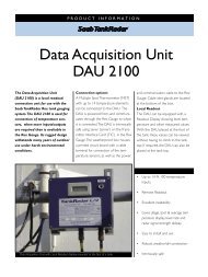
EEx ia II C T4Tamb = -40°to +65°CBASEEFAEx91C2069Umax:in = 28 VDC Wmax:in = 1.3 WImas:in = 394 mADCCeq = 0 Leq = 0A division of Saab Marine ElectronicsAmbient temperature -40°to +65°CABListed 9390MADE IN SWEDENTechnical DescriptionData Acquisition UnitsThe Data Acquisition Unit (DAU) is used togetherwith an associated Radar <strong>Tank</strong> Gauge for localreadout and for connection of temperature sensors,pressure transmitters, on/off switches etc whenmore inputs/outputs are required than is availablein the RTG.There are two versions of the Data Acquisition Unit,the Slave DAU and the Independent DAU.Slave Data Acquisition Unit DAU 2100A Multiple Spot Thermometer (MST) with up to 14temperature elements can be connected to the SlaveDAU. The unit is powered from, and communicatesthrough the Radar <strong>Tank</strong> Gauge to which it isconnected. The Slave DAU is intrinsically safeusing zener barriers on the Transmitter InterfaceCard (TIC) in the Radar <strong>Tank</strong> Gauge.The weatherproof box houses a printed circuitboard with a cable terminal for connection of thetemperature sensors, as well as the power andcommunication cable. Cable inlet cable glands arelocated at the bottom of the box.The Slave Data Acquisition Unit withLocal Readout Display mounted at thefoot of a tank.LCD display forlocal readout0.28 m (11 in.)0.23 m (9 in.)Data Acquisition Unit Type DAU 2100Hazardous Location Class I Group Cand D. T emperature Code T4.Intrinsically safe for use in connectionwith Radar Unit TH 2000- TH 2014.See control drawing 9150 057-901Warning: any substitution of componentsmay impair intrinsic safetySee service manualSerial no:UI:For intrinsically safe circuits onlyCable glands (not for US market)DAU 2100 Slave Data Acquisition Unit.24
EEx ia II C T4Tamb = -40 °to +65°CBASEEF AEx91C2069Umax:in = 28 VDC Wmax:in = 1.3 WImas:in = 394 mADCCeq = 0 Leq = 0Serial no:EEx ia II C T4Tamb = -40 °to +65°CBASEEFAEx91C2069Umax:in = 28 VDC Wmax:in = 1.3 WImas:in = 394 mADCCeq = 0 Leq = 0Serial no:UI:A division of Saab Marine Electronics ABFor intrinsically safe circuits only"i"W11Data Acquisition Unit Type DAU 2100UI:A division of Saab Marine Electronics ABFor intrinsically safe circuits onlyHazardous Location Class I Group Cand D. T emperature Code T4. The deviceprovides intrinsically safe outputs.See control drawing 9150 057-901Warning: any substitution of any componentsmay impair intrinsic safety .See service manualAmbient temperature -40°to +65°C©Listed 9390MADE IN SWEDEN©Listed 9390MADE IN SWEDENSaab <strong>Tank</strong>Radar RexIndependent Data Acquisition Unit DAU 2130Also to the Independent DAU a Multiple SpotThermometer with up to 14 temperature elementscan be connected. In addition the unit has four 4-20mA inputs, eight digital inputs and four relayoutputs.The Independent Data Acquisition Unit is used forconnecting temperature sensors, various pressuresensors, as well as other types of sensors, such aswater interface sensors in case they are not directlyconnected to the RTG. The Independent DAU canalso be equipped with four relays for controllingother equipment.The Independent DAU has its own power supplyand communicates directly on the TRL/2 Bus.Part of the Independent DAU is intrinsically safe,part of it is explosion proof. The non-intrinsicallysafe circuits are placed in a flameproof enclosurewhere the power, communication and relay cablesare connected. The intrinsically safe sensors areconnected at the bottom of the weatherproof box.0.33 m (13 in.)Cable inlets for power, TRL/2Bus and relay outputData Acquisition Unit Type DAU 2130FlameproofenclosureLCDdisplay forlocalreadoutLocal ReadoutBoth types of DAU:s can be equipped with aReadout Display showing level, temperature andother measured values. With the DAU placed at thefoot of the tank, these values can be viewed at thetank without having to climb to the tank top.If required, the DAU can also be placed at the tank top.0.28 m (11 in)Cable inlets forintrinsicallysafeconnectionsTRL/2 BusW12FORINTRINSICALLYSAFE CIRCUITSONLYRTGHazardous Location Class I Group A, B, Cand D. Temperature Code T4.Intrinsically safe for use in connectionwith Radar Unit TH 2000- TH 2014.See control drawing 9150 057-901Warning: any substitution of componentsmay impair intrinsic safetySee service manualAmbient temperature -40°to +65°CIndependentDAU<strong>Tank</strong>DAU 2130 connection to TRL/2 Bus.25
Technical DescriptionTechnical Data For Both Types of DAU:sAmbient operating temperature:-40° C to 70° C (-40° F to+158° F)Number of sensor elements:Max. 14 per DAUTemperemperature ranges:Range 1: -50° C to 125° C (-58° F to 257° F) Range 2: -50° C to 300° C (-58° F to 572° F)Range 3: -200° C to +150° C (-330° F to 302° F)Temperemperature resolution: 0.1° C (0.18° F)Accuracy (excl. sensor): ±0.2° C (±0.36° F)[for -20° C to 100° C (-4° F to 212° F)]±0.5° C (±0.9° F) [for other ranges]Sensor elements:Pt 100 single or multispot.Display y (optional):LCD with 6 digits,Availabvailable le data on display:Level, Ullage, Spot temperature, Average temperature, Level rate, Signal strength.Ingress protection: IP 66 & 67.Technical Data for Slave DAU 2100Explosion protection:EEx ia IIC T4 (EN50020 Europe) and Class 1, Div I, Groups C and D (UL913 USA).See also the list on page 43. Approvals for Installation in Hazardous Areas.Power Supply:Intrinsically safe supply from Radar <strong>Tank</strong> GaugeField bus:Intrinsically safe local line from Radar <strong>Tank</strong> GaugeTechnical Data for Independent DAU 2130Explosion protection:EEx d[ia] IIB T4 (EN50014, EN50018 and EN50020 Europe) Class 1, Div I, Groups C and D (UL1203,UL913 USA). See also the list in page 43. “Approvals for Installation in Hazardous Areas.”Power Supply:115 or 230 VAC, +10% to -15%, 50-60 Hz, max. 10 W Field bus. TRL/2 BusAnalog inputs:4-20 mA. Intrinsically safe. Max. 4. Multiplexed (only one is powered at a time)Status and frequency inputs:Max. 8. Intrinsically safeRelay y outputs (option): Max. 4Relay y contact rating:250 VAC / 5A (resistive load)26
LevelmSaab <strong>Tank</strong>Radar RexRemote Display UnitRDU 40The Remote Display Unit (RDU 40) is a robustdisplay unit for outdoor use in hazardous area. Ifthe number of temperature elements per tank is 6 orless, the RDU 40 is the most cost-effective solutionfor field display. In this case the temperatureelements can be connected directly to the<strong>Tank</strong>Radar gauge (RTG) without using a DataAcquisition Unit (DAU). The display functions aresoftware controlled by the connected <strong>Tank</strong>Radargauge. It is easy to work with via the 4-key displaykeyboard. Each screen view can display 7 text lineswith 16 characters per line.The RDU 40 is connected by a 3-wire cable up to100 m (330 ft) from the RTG. Up to two units can beconnected to one <strong>Tank</strong>Radar Rex gauge. It displayscalculated data, such as level, average temperature,volume, signal strength, etc. The data can bedisplayed in lists or as single values in very easilyreadable 25 mm (1 inch) solid fonts. The operatorcan set up a user-defined window where the mostuseful information is presented. This window willbe shown as the default view. TheRDU 40 can view up to six spot temperatureelements connected to a <strong>Tank</strong>Radar Rex gauge.The rugged design of the RDU 40 makes it withstand many years ofoutdoor use under harsh environmental conditions.6.767The RDU is connected toThe <strong>Tank</strong>Radar Rex gauge.Technical Data for RDU 40View/Software: Available data: Level, Ullage, Spot temperature , Average temperature,Volume, Level rate, Signal strength,Electrical:Display type: Graphic LCD display 128 x 64 pixelsAmbient temperature:-20°C to 55 °C (-4°F to 130 °F)Hazardous locations certifications: Cenelec Ex ib IIC T4FM: Class 1 Div 1 Group A, B, C, DMax cable length:100 m (330 ft) (total length if two units are connected to the same gauge)Mechanical: Material housing: Die cast aluminiumDimensions (width x height x depth): 150 x 120 x 70 mm (6 x 4 x 3 inch)Weight:1.2 kg (2.6 lbs)Cable entry:2 x M20, 1x M25Optional:½ inch NPT and ¾ inch NPT by external adaptersIngress protection: IP 66 & 6727
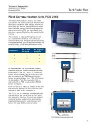
Serial no:Serial no:Field Connection Unit Type FCU 2160UI:A division of Saab Marine Electronics ABA division of Saab Marine ElectronicsUI:MADE IN SWEDENABMADE IN SWEDENTechnical DescriptionField Communication Unit FCU 2160The Field Communication Unit (FCU) is a dataconcentrator that continuously polls data from fielddevices such as Radar <strong>Tank</strong> Gauges, Data AcquisitionUnits and Remote Display Units and stores them ina buffer memory. Whenever a request for data isreceived, the FCU can immediately send data froma group of tanks from the updated buffer memory.The FCU acts as a slave on the group bus and as amaster on the field bus. The unit has sixcommunication ports. The ports can be individuallyconfigured as either group bus ports or as field busports according to one of the alternatives below:Alternative No. of field No. ofbus ports group bus ports1 4 22 3 33 2 4Group busesFCUAn interface board can be connected for eachcommunication port. These boards can be eitherFCM boards for the TRL/2 Bus or FCI boards forRS-485 communication. Two group bus ports canalso be configured as RS-232 by connecting ajumper connector instead of an FCM or FCI board.As standard the Field Communication Unit isdelivered with six FCM boards and two RS-232jumper connectors.Each RTG and each Independent DAU has anindividual address on the field bus. Slave DAU:sand RDU:s use the same address as the RTG theyare connected to and do not have separateaddresses.Two FCU:s can be connected in parallel with oneunit operational and one working as “hot” redundantbackup for the other. The units are softwaremonitored and the backup unit is automaticallytriggered and activated in case of primary unitfailure. See page 41 for more information.0.23 m (9 in.)0.28 m (11 in.)Field Connection Unit Type FCU 2160Cable InletsFieldbusesFCU 2160 Field Communication Unit.28
Saab <strong>Tank</strong>Radar RexTechnical Data for FCU 2160Explosion protection:NoneAmbient operating temperature:-40° C to 70° C (-40° F to 158° F)Power Supply:115 or 230 VAC, +10% to -15%, 50-60 Hz, max. 10 W.Ingress protection: IP 65.Communication:Field bus ports: TRL/2 Bus, modified Modbus protocol.Total number of RTG:s andIndependent DAU:s per field bus port: Max 8.Group bus ports:TRL/2 Bus, RS 232 or RS 485, Modbus based protocol.Group bus baud rate:Programmable up to 19 200 Baud.Host communication via group bus ports: Various protocols available, see page 32.Number of tanks per FCU: With RTG:s and Slave DAU:s or RDU:s: Max 32 (max 8 per field bus).With RTG:s and Independent DAU:s: Max 16 (max 4 per field bus).The FCU works as a data concentrator for a group of tanks ensuring fast data communication from the tanks to the control room.29
MADE IN SWEDENTechnical DescriptionField Bus Modem, FBM 2171The Field Bus Modem (FBM) converts the signalfrom RS-232 to the TRL/2 Bus. It is used to connecta PC with the <strong>Tank</strong>Master HMI software to theTRL/2 Bus. The Field Bus Modem is delivered withthe cable for connection to the PC. The Field BusModem has its own power supply through an AC/DC converter.mm (inch)Connectionto PCDCconnectorField Bus ModemTyp FBM 2170RS-232120 (4.7)TRL/2 Bus1 2 3 4A division of Saab Marine Electronics ABFBM 2170 Field Bus Modem.Connection to Field busTechnical Data for FBM 2171Explosion protection:NonePower supply:From AC/DC converter suppliedby Saab Rosemount <strong>Tank</strong> Control(6-15 V, 10 mA).Cable to PC:3 m (10 ft) included in delivery.Field bus overvoltage protection:Galvanic insulation, transient protection,suppressors and fuses.30
EEx ia II C T4Tamb = -40°to +65°CBASEEFAEx91C2069Umax:in = 28 VDC Wmax:in = 1.3 WImas:in = 394 mADCCeq = 0 Leq = 0Serial no:EEx ia II C T4Tamb = -40 °to +65°CBASEEFAEx91C2069Umax:in = 28 VDC Wmax:in = 1.3 WImas:in = 394 mADCCeq = 0 Leq = 0Serial no:Data Acquisition Unit Type DAU 2130Hazardous Location Class I Gorup Cand D. T emperature Code T4. The deviceData Acquisition Unit Type DAU 2130Hazardous Location Class I Gorup Cand D. T emperature Code T4. The deviceprovides intrinsically safe outputs.See control drawing 9150 057-901Warning: any substitution of any componentsmay impair intrinsic safety.See service manualAmbient temperature -40°to +65°CUI:A division of Saab Marine Electronics ABFor intrinsically safe circuits onlyprovides intrinsically safe outputs.See control drawing 9150 057-901Warning: any substitution of any componentsmay impair intrinsic safety.See service manualAmbient temperature -40°to +65°CUI:A division of Saab Marine Electronics ABFor intrinsically safe circuits onlyListed 9390MADE IN SWEDENListed 9390MADE IN SWEDEN"i""i"W11W11"i"W11EEx ia II C T4Tamb = -40 °to +65°CBASEEFAEx91C2069Umax:in = 28 VDC Wmax:in = 1.3 WImas:in = 394 mADCCeq = 0 Leq = 0Serial no:Data Acquisition Unit Type DAU 2130Hazardous Location Class I Gorup Cand D. T emperature Code T4. The deviceUI:A division of Saab Marine Electronics ABFor intrinsically safe circuits onlyprovides intrinsically safe outputs.See control drawing 9150 057-901Warning: any substitution of any componentsmay impair intrinsic safety.See service manualAmbient temperature -40°to +65°CListed 9390MADE IN SWEDENEEx ia II C T4Tamb = -40°to +65°CBASEEFAEx91C2069Umax:in = 28 VDC Wmax:in = 1.3 WImas:in = 394 mADCCeq = 0 Leq = 0Serial no:Data Acquisition Unit Type DAU 2100Hazardous Location Class I Group A, B, Cand D. T emperature Code T4.Intrinsically safe for use in connectionwith Radar Unit TH 2000- TH 2014.See control drawing 9150 057-901Warning: any substitution of componentsmay impair intrinsic safetySee service manualAmbient temperature -40°to +65°CUI:A division of Saab Marine Electronics ABFor intrinsically safe circuits onlyListed 9390MADE IN SWEDENSaab <strong>Tank</strong>Radar RexJunction BoxesAs optional equipment a series of junction boxescan be delivered with the <strong>Tank</strong>Radar Rex system.They are used to connect the various system units.(The junction box integrated in the TransmitterHead is described on page 15.)Note: Other junction boxes are available for the USmarket.Junction Box JB 8 for connection of RTGto Slave DAUJunction Box JB 8 should only be used forintrinsically safe connections. It can be used when aSlave DAU or an RDU 40 is located more than 2 maway from the RTG. It contains eight terminals andtwo openings with PG 16 glands cable diameter 11-15 mm.Junction Box JB 16 for connection toRTG and Independent DAUJunction Box JB 16 is an EEx “e” approved junctionbox. It can be used to connect power and TRL/2 Busto the RTG and the Independent DAU. It includes16 terminals, a flexible hose for the cabling to theRTG or Independent DAU, a mounting plate andvarious openings for glands for PG16-21. Fourglands are included for cable diameters 8-18 mm.Note: EEx “e” is not an approved protection on allmarkets.~2 m wireswithprotectivehoseTHJB 16JB 16 forRelay OutputIndependentDAUFour PG 21DAUTHW12FORINTRINSICALLYSAFE CIRCUITSONLY~2 m wires withprotective hoseJB 16Two PG 16SignalPower 230/1 15 VCableTwo PG 16~ 2 m wires withprotective hoseW12FORINTRINSICALLYSAFE CIRCUITSONLYJunction box JB 16.Junction box JB 8.Junction Box JB 12 for connection ofRTG to Slave DAUJunction Box JB 12 should only be used forintrinsically safe connections. It includes 12 wireterminals, various openings for glands fromPG 13.5-PG 16. Six glands PG 13.5 for cablediameters 11-15 mm are included.Junction Box JB 36 for connection oftemperature sensorsJunction Box JB 36 can be used for the intrinsicallysafe connection of up to 14 temperature sensors to aData Acquisition Unit (12 if 3-wire connection isused). The DAU may also be placed on top of thetemperature sensors.DAUAnaloginputsAnalogoutputsCableSix PG 13.5~ 2 m wires withprotective hoseTHW12FORINTRINSICALLYSAFE CIRCUITSONLYDAUExtensioncableTwo PG 21One PG 16TemperatureelementsTwo PG 16Junction box JB 12.Junction box JB 36.31
LevelTemp AvgPre sureLevelTemp AvgPre sureValue Entry<strong>Tank</strong>1Value Hi Lim Lo Lim H Lim LimAutoAutoAuto18. 0120.02.000.2 000Delay Hyst5.00.52. 080.00.020. 0 1. 0Leak LimitEnter CancelNew <strong>Tank</strong>0.2 0EnableTechnical DescriptionConnection to other systemsThe Saab <strong>Tank</strong>Radar Rex system can be connectedto all major suppliers of DCS, SCADA systems,plant host computers or terminal automationsystems. The connnection can be made in two ways:• To a <strong>Tank</strong>Master PC workstation.• Directly to a Field Communication Unit.The advantage of connecting to a <strong>Tank</strong>Masterworkstation is that not only the measured values,but also the values calculated by the <strong>Tank</strong>Mastercan be communicated.Examples of available protocols is given below.Certified test reports are available for most of theprotocols.If you require a protocol which is not included inthe list, contact Saab Rosemount as new protocolsare developed on a regular basis.FBMFCUTMFCUFBMMeasured data:Level, Temperature, Pressure, etc.Calculated data:Volume, Mass, Density, etc.Measured data:Level, Temperature, Pressure, etc.The host computer can be connected either to a <strong>Tank</strong>Master(TM) PCor directly to the FCU.Communication protocols (examples only, more are available)Vendor Unit Rex Unit InterfaceAllen-Bradley ® PLC-5 <strong>Tank</strong>Master RS-232 Data <strong>High</strong>way PlusAllen Bradley ® PLC-5 (CSI) OPI RS-232/485 ModbusAllen Bradley ® PLC-5 (Wonderware) OPI RS-232/485 ModbusBailey ® B90 FCU RS-232/485 ModbusCSI ® Allan Bradley 1771 OPI RS-232 ModbusBasic ModuleDEC ® Not hardware OPI Ethernet Decmessage QdependentE+H ® MDP -11-1/F <strong>Tank</strong>Master RS-232 ModbusENRAF ® CIU OPI RS-232 ModbusENRAF ® Microlect FCU+PC RS-232 EnrafENRAF ® MODCIU FCU RS-232 ModbusENRAF ® MSU PC-ENTIS OPI RS-232 EF_CIU protocolFisher Controls ® CL6921 (Provox) FCU RS-232 ModbusFoxboro ® I/A Gateway (MDG) FCU RS-232/485 ModbusFoxboro ® I/A Gateway (MDG) OPI RS-232/485 ModbusHoneywell ® PLCG, APM-SI or CLM FCU RS-232/485 ModbusHoneywell ® APM-SI OPI EthernetHoneywell ® S-9000 OPI RS-232/485 ModbusIBM ® IBM9121 OPI SDLCRosemount ® RS 3 FCU RS-232/485 ModbusSiemens ® S5 FCU RS-232 ModbusVega ® Vegacom 556 OPI RS-232Yokogawa ® Centum-XL EFGW FCU RS-232/485 ModbusYokogawa ® Centum-CS FCU RS-232/485 Modbus(OPI is the previous generation HMI software.)32
Saab <strong>Tank</strong>Radar Rex<strong>Tank</strong> inventory, density & hybrid calculationsThe <strong>Tank</strong>Radar Rex gauge, with its high capacitysignal processor is designed to make basicinventory calculations directly in the gauge, or giveprecise inputs for complete tank calculations inanother computer. The gauge can receive andprocess signals from analog and digital pressuretransmitters, water bottom sensors etc. Timeconsuming manual density measurements can beavoided. All measured data are transmitted on thefield bus and can be further processed in the controlroom by the <strong>Tank</strong>Master PC software or by theplants host computer/DCS system.Density measurement with pressure transmittersWhen the RTG is connected with a pressuretransmitter near the bottom of the tank, the densityof the product can be calculated and presented online.The accuracy of the density calculation largelydepends on the accuracy of the pressure transmitter.Saab <strong>Tank</strong>Radar Rex can interface to any pressuretransmitter with a standard output of 4-20 mA orHART. The 4-20 mA signal is converted fromanalog to digital form in the RTG.The standard pressure transmitter supplied withthe <strong>Tank</strong>Radar Rex system for in-liquid mounting isRosemount 3051.The gauge calculates (or receives inputs for)the following data:•Gross volume using the tank strapping table(100 strapping points).• Mass (if pressure sensor connected)• Observed density (if pressure sensorconnected)• Level (corrected for thermal tank wallexpansion)•Temperature• Oil/Water interface level.•All data is calculated according to updatedAPI and ISO standards. The temperaturecalculations include API algorithms tohandle elements close to the bottom.• The level value is software corrected forchanges in tank reference height.Both metric and USA/UK units are supported.If net volume calculations with very high accuracyusing up to 2000 strapping points are required, the<strong>Tank</strong>Master PC software package is to be used, seepage 34. Normally less than 100 points per tank arenecessary for 1 liter accuracy. <strong>Tank</strong>Master is usingquadratic interpolation for spheres and horizontalcylinders, which increases volume accuracy andreduces number of strapping points.<strong>Tank</strong>MasterField BusModemTRL/2 BusFieldCommunicationUnit• Level• Temperature• Density• Volume• MassRadar <strong>Tank</strong>GaugeDataAcquisitionUnitTemperatureSensorsPressureSensorTo OtherFCU:sBy complementing the level measurement with temperature andpressure measurement, the density of the product in the tank can becontinuously calculated and provided on-line.33
Technical DescriptionWater interface measurementThe capacitive Water Bottom Sensor WBS 500continuously measures free water level below theoil surface and provides input for on-line netinventory. The sensor is integrated with theMultiple Spot Thermometer. WBS 500 outputs a 4-20 mA signal, which is connected directly to anRTG, or to an Independent DAU. There is a Pt100temperature sensor inside the probe at the bottom,allowing measurements at low levels. The WBS 500is detachable for repair.Technical Data for WBS 500Hazardous locationscertiftifications:ications: EEx ia IIB T5 (EN 50014, EN 50020)Accuracy:2 mm (0.08 in.)Repeatability:±0.5 mm (0.02 in.)Product temperature:0° C to 60° C (32° F to 380° F)Storage temperature:-40° C to 90° C (-40° F to 194° F)Max. pressure:5 bar (73 psig)Active length:Standard: 500 mm (20 in.)Option: 300-1500 mm (12-60 in.)Cabling:Shielded pair. Min. 0.75 mm 2Material exposed totank atmosphere:Acid proof steel type 316, PTFE(Teflon®), FEP, Viton®The WBS 500 Water Interface Sensor measures thelevel of the interface in most types of tanks but isnot recommended for use in crude oil.A typical applicationThe WBS 500 is installed together witha MST to be hung from the top of thetank. The vertical position is chosenaccording to the actual bottom waterrange. The WBS 500 should be anchoredto the tank bottom to ensure a fixedposition in case of turbulence.mm (inch)Protective cablehose or MultipleSpot ThermometerConnectionActive length (L) =Standard: 500 (19.69)Option: 1000 (39.37) or 1500 (59.06)L+340 (13.39)Sensor electrodeOptional temperaturespot element Pt100Multiple SpotThermometer<strong>Tank</strong> wallWBS 500Interface level38 (1.50)Anchoringfacility34
Saab <strong>Tank</strong>Radar Rex<strong>Tank</strong>Master HMI software•WinOpi is a complete inventory softwarepackage.<strong>Tank</strong>Master is a powerful Windows-based HumanMachine Interface (HMI) for complete tankinventory management. It provides configuration,service and set up, inventory and custody transferfunctions for <strong>Tank</strong>Radar Rex systems. Allcalculations are based on current API and ISOstandards. <strong>Tank</strong>Master follows the OPC standardand can communicate with Microsoft® programsand OPC compatible systems like Intellution’s iFIX ®and Wonderware’s InTouch ® . <strong>Tank</strong>Master isdeveloped and supported by Saab Rosemount <strong>Tank</strong>Control. <strong>Tank</strong>Master has two main softwaremodules:•WinSetup is the software package used forconfiguration of the total Rex system.The WinSetup package is included with all<strong>Tank</strong>Radar Rex deliveries as a set-up andconfiguration tool. Other functions are optionsdepending on which package is used.Available main functions in <strong>Tank</strong>Master includethe following:Interactive configuration and installation withset-up wizard<strong>Inventory</strong> and custody transfer functions• Real time tank gauging data such as level,temperature, water interface level and pressure.•Real time, gross and net volume inventorycalculations based on API and ISO.• Hybrid tank gauging with pressure inputsgiving data for density and mass calculation.•Metrologically sealed data.• API calculator.<strong>Tank</strong>Master distributes essentialinventory tank gauging data.SCADAOPC Client LevelEngineeringManagementEthernetModbusModbus<strong>Tank</strong>MasterOPC Server<strong>Tank</strong>MasterOPC ServerDCSModbusTRL2 Field BusFCU<strong>Tank</strong> Data, Level, Temperature, Pressure, Volume etcPLC35
Technical DescriptionReports and data sampling• Batch report for internal and externaltransfers.•Customized Reports to Microsoft Officeprograms.• Automatic reports.• Reports via e-mail.• Audit log for events.• Historical data sampling.<strong>Tank</strong>Master gives the most important inventory data for a specific tankin one easy-to-read window.Networking and interfacing•OPC server with browser for easy interfacewith other plant computer systems.• Full network capabilities.• SCADA / DCS communication via MODBUS.• SCADA / DCS communication via OPC.• Integration with other tank gauging systemsby taking in and displaying data from othervendors’ gauges.Alarms• Reliable alarm handling of measured valueswith high, high-high, low and low-low levelalarms.• Alarms to mobile phones.• Alarms via e-mail.• Leakage alarms based on net volume.You can easily organize the tanks in e.g. geographical or product groups,with associated sub-groups. For example you can choose to see theactual tank gauging and inventory data in a bargraph group, giving a quickoverview of tank farm activity.36
Saab <strong>Tank</strong>Radar RexOthers• User manager with different access levels forpersonnel.• Customized views with graphic plantlayouts.• Easy translation to other languages thanEnglish.• Advanced group configuration ingeographical or product groups etc.• Compatibility with Saab’s earlier platformOPI which can easily be replacedby <strong>Tank</strong>Master.PC RequirementsRequired operating system:Windows 2000, NT 4.0 SP5 or later. DistributedCOM (DCOM), which is used for networkcomputing.Required hardware (PC):Windows 2000/NT approved PC. 350 MHz Intel orcompatible. 128 MB RAM. 4 GB disk drive(<strong>Tank</strong>Master requires approx. 200 MB).Graphics card 1024*768 pixels, 65536 colors.Required hardware (network server PC):1-2 Network clients – same/better performance onthe server than on the client PC.3 or more Network clients – 500 MHz Intel orcompatible, 256 MB RAM on the server PC.For further information a separate <strong>Tank</strong>Masterbrochure is avaialble.The “tank farm explorer” makes it easy to navigate in <strong>Tank</strong>Master. Justlike in “Windows explorer” it is possible to expand and minimize fieldsand get direct group and tank access by double-clicking the specificgroup or tank icon.37
Technical DescriptionRadio LinkIt is possible to use a high speed UHF Radio Linkinstead of cable between the control room and theField Communication Unit (FCU). The link consistsof two small size UHF radio modems that areconnected to the serial RS-232 port on the<strong>Tank</strong>Master PC and to the group bus port of an FCU.The Radio Link is completely transparent andworks just like a cable connection. A HostComputer can also be connected using the samemethod.Depending on the antennas and the surroundingtopography the range is up to five kilometers (threemiles). Longer distances can be covered by usingdirectional antennas.Rex<strong>System</strong>FCURadioModemRadioModem<strong>Tank</strong>MasterPCUsing a radio link can reduce the cable cost betweenhost computer and FCU.Technical Data for Radio LinkAnntenna:Arrangement for 450 MHzFrequency range:405 - 470 MHz,Basic tuning range:2 MHzChannel separation:ation:25 kHzNumber of channels: 16Transmitteransmitter: RF Power: 500 mW / 50ΩDeviation:±2,5 kHzAdjacent channel power: < 200 nWSpurious radiation:Meets ETSI 300-113Receiver er Sensitivity:< - 108 dBmRadio Modem: Ambient temperature: -25°C to + 55 °C (-13° F to 131 °F)Size:11 x 65 x 26 mm (0.43 x 2.6 x 1.0 inch)Weight:260 g (0.6 lbs)Power supply:12 VDC at 500 mA maxApprovals:Sweden, Finland, Denmark, U.K., Switzerland, Hong Kong, FCC approval pending38
Saab <strong>Tank</strong>Radar RexSaab <strong>Tank</strong>Radar Rex <strong>System</strong> ConfigurationsThe Saab <strong>Tank</strong>Radar Rex <strong>System</strong> can be applied toa single tank or to large and very complex systems.All system configurations are based on the samebasic parts.TMorDCSFBMTRL/2 Group BusTRL/2 Group BusTMorDCSFBMThe TRL/2 Bus - A fast and reliable data busIn the descriptions below the TRL/2 Bus is dividedinto two parts:•Group bus• Field bus.Both buses work in the same way with the sametechnical specifications. However, the Group Bus isdefined as the TRL/2 Bus between the<strong>Tank</strong>Master/host computer and the FCU:s, whilethe field buses connect the DAU:s, RDU:s and theRTG:s with the FCU:s.<strong>Tank</strong>Master communicates on the TRL/2 Bus via aField Bus Modem. The Field Bus Modem translatesthe signals from RS-232 to TRL/2 Bus and vice versa.The TRL/2 Bus was developed to minimize theupdating times as well as to provide a robust andreliable field bus for transferring the measuredvalues from the tanks to the control room.The recommended maximum total number of RTG:splus IDAU:s on one field bus is 8 (The maximumnumber of RTG:s plus IDAU:s per FCU:s is 32).This means for example that for tanks with RTG:sand SDAU:s (or RDU:s) there should be max 8tanks per field bus. Each Field Communication Unitcontinuously collects data from up to four TRL/2field buses and stores the values in a buffermemory. When a query reaches the FieldCommunication Unit from the <strong>Tank</strong>Master or froma plant host computer on the group bus, it canquickly send data directly from the database.FCU FCU FCU FCU FCU FCUUp to 8units on eachTRL/2 BusR TG /DAUUp to four TRL/2 Field Buses from each FCUR TG /DAUR TG /DAUTRL/2 Field BusR TG /DAUR TG /DAUUp to 8TRL/2 BusR TG /DAUFigure showing how the TRL/2 Bus is used in the <strong>Tank</strong>Radar Rex system.Technical Data for TRL/2 field busNumber of units:Max 8 units arerecommended on one TRL/2 Bus.(Each RTG and each IDAUcorresponds to one unit.)Cable:Twisted and shielded pairCable area: Min 0.50 mm 2 AWG 20Cable length:Max 4 km (2.5 miles)Modulation type:FSK (frequency shift keyed), half duplex39
A division of Saab Marine Electronics ABField Bus ModemTyp FBM 2170RS-232TRL/2 Bus1 2 3 4MADE IN SWEDENTechnical DescriptionStand-Alone ApplicationA stand-alone Radar <strong>Tank</strong> Gauge can be used tomeasure on a single tank. The measured level isoutput on the field bus or as an analog 4-20 mAsignal. The RTG can also include 4-20 mA inputs ortemperature inputs.FBMFCU<strong>Tank</strong>MasterMax. 15 m(45') withoutan FBM<strong>Tank</strong>MasterFCUA Slave Data Acquisition Unit or an RDU can beconnected to the stand-alone gauge.<strong>Tank</strong> groupsThe connection between <strong>Tank</strong>Master and FCU.<strong>Tank</strong> groupsAnalog outputsAnalog inputsLevel6.767 mPower230/115VConnecting the Field CommunicationUnit FCU 2160The FCU is very flexible. There are six communicationports on the FCU. Normally four of these ports areused for field buses. However, it can have up tofour group bus ports.The FCU can handle up to 32 RTG:s and 32 DAU:s(or RDU:s). Each field bus could connect up to 16units (RTG:s and/or Independent DAU:s. One RTGwith one Slave DAU or RDU is considered as oneunit ). However in order to ensure robust datacommunication maximum 8 units are recommendedper field bus.In a stand-alone configuration the analog output can be used to connectan analog display. If connecting a Slave Data Acquisition Unit or theRDU 40, all measured values can be displayed.To increase the updating speed of the FCU, thenumber of connected RTG:s and DAU:s should beapproximately the same on each field busconnected to one FCU.<strong>System</strong>s with a <strong>Tank</strong>Master Work StationThe <strong>Tank</strong>Master PC can be connected via RS-232directly (without a Field Bus Modem) to one FieldCommunication Unit if the FCU is placed close tothe PC. If more than one FCU is used, FBM:s orRS 485 communication is required.Normally the Field Bus Modem, FBM, is connectedto the <strong>Tank</strong>Master PC. The FBM is then connected tothe FCU and uses the TRL/2 Bus. The FCU does notneed to be close to the <strong>Tank</strong>Master PC in this case.RTG/DAUFCURTG/DAUShorterUpdatingTimesRTG/DAURTG/DAURTG/DAULongerUpdatingTimesRTG/DAURTG/DAUFCURTG/DAUThe updating times are improved if the units are evenly spread out onthe field buses of the FCU.Both communication ports of the <strong>Tank</strong>Master can beused to connect TRL/2 group buses.40
Saab <strong>Tank</strong>Radar RexRedundant connection of FieldCommunication UnitsThe Field Communication Units can be connectedin parallel to provide automatic redundancy in theSaab <strong>Tank</strong>Radar Rex system.Redundancy can be made in different ways:• The FCU can connect up to four group buses withdifferent masters asking the FCU for data. Asystem can for example have two <strong>Tank</strong>MasterPC:s connected via two different group buses.•Using two FCU:s provides redundancy on bothFCU and host computer level. With two FCU:sconnected in parallel to the field buses, one ofthe FCU:s will be configured as the primary FCUand will be in an active state. The other FCU willbe in a back-up state. The backup FCU listensto the communication on the field bus. If thecommunication on the field bus ceases for acertain delay time, the backup FCU will takeover and communication will be resumed. Amessage is sent to the <strong>Tank</strong>Master (or DCS) thatthe primary FCU has failed and that the backupFCU has taken over the communication.•A complete redundancy from control room toRTG:s and DAU:s is achieved by using doubleFCU:s as well as double <strong>Tank</strong>Master work stations.TMorDCSTMTMorDCSFBMFCUFCUGroup BusesTMorDCSTRL/2 Group BusesField Bus 1Field Bus 2DCSFCUField Bus 1Field Bus 2Field Bus 3TMorDCSThere can be up to four connections to <strong>Tank</strong>Master (TM) or DCS unitson the Group Bus ports of the FCU.By using double FCU:s, the FCU:s can be made redundant as well.DCSTMTMFBMFBMFCUFCUField Bus 1Field Bus 2Field Bus 3Field Bus 4Two FCU:s and two <strong>Tank</strong>Master work stations provide a high degree ofredundancy.41
Technical DescriptionExample of a General <strong>System</strong>The figure below shows an example of a generalSaab <strong>Tank</strong>Radar Rex system.TMDCSPlant HostComputer(DCS)AlternativeconnectionsRS-232RS-232FBMRS-232FBMFCUPortableServicePCTRL/2 Group BusTRL/2 Group BusFCUFCUFCUTRL/2 Field BusesTRL/2 Field BusTRL/2 Field BusRTG/DAURTG/DAURTG/DAURTG/DAURTG/DAURTG/DAUTRL/2 Field BusAnalogOutTRL/2 Field BusSlaveDAURTGRTG/DAURTG/DAUIndependentRTG RTG RTG/DAUDAURTG/DAUAnalogIn42
Saab <strong>Tank</strong>Radar RexCertificatesThe list below includes the certificates andapprovals of the Saab <strong>Tank</strong>Radar Rex system at thetime of the printing of this description. Please notethat the list does not give any detailed informationon each certificate or approval. There may berestrictions in them, for example, a certificate maybe valid for only parts of the Saab <strong>Tank</strong>Radar Rexsystem. Saab Rosemount <strong>Tank</strong> Control should becontacted if you require more information on any ofthe certificates.Accuracy approvals / Legal metrologicalcertificates• OIML R85 (E) International• BEV, Austria• Belgium Metrological Inspection, BMS, Belgium• China Metrological Institute, China• Physikalisch Technische Bundesanstalt, PTB,Germany• Ministry of Civil Supplies, W & M, India• Nederland Meet Institute Ijkwesen, NMI,The Netherlands• SIM, France, pending• GUM, Poland• BRML, Romania• GOSStandart, Russia• Statens Provningsanstalt, SP, Sweden• SIRIM, Malaysia• Thai Excise and Customs, Thailand• GOSStandart, UkraineApprovals for installation in hazardousareas• BASEEFA / CENELEC, Europe• Underwriters Laboratory, UL, USA•C-UL, Canada• JIS, Japan, part of approval pending• TÜV, Austria• PTB, Germany (Zone 0 approval)• GOSStandart, Russia• GOSStandart, Ukraine• Department of Explosives, IndiaEmission ApprovalsThe listed approvals below deal with how muchradiated power that is sent out from the radargauge. In most countries there are no formulatedrequirements on equipment like a radar gauge, dueto the very low output power and the fact that it isnormally installed in a metallic tank. Saab <strong>Tank</strong>Radarhas been tested in accordance with CISPR-22 andCISPR-16.The certificates listed below are exceptionsfor specific countries:• Bundes Ministerium für Post undTelekommunikationen, BMPT, Germany• Federal Communications Commission, FCC, USA• Post und Telegraf Direktion, Austria• Department of Trade and Industry / RadioCommunication Agency DTI / RCA, UnitedKingdomIn addition to the accuracy approvals listed above,many countries are presently in the process todefine custody transfer requirements.43
Technical DescriptionMiscellaneous Approvals• CE Mark, European Community• TÜV Overfilling Protection, Germany• TÜV Pressure Approval, Germany•TÜV Firesafe Approval, GermanyIn addition to the list above, there are a number ofcertificates or approvals for optional equipmentwhich can be delivered by Saab Rosemount <strong>Tank</strong>Control. Junction boxes, pressure transducers,water interface sensors, etc. have approvals in thename of their manufacturers. Copies of these can berequested from Saab Rosemount <strong>Tank</strong> Control.Vapor Influence on Radar MeasurementFor a few specific products there can be ameasurable influence on the level accuracy, if thecomposition of the vapor varies between no vaporand fully saturated vapor condition. However,there is no noticeable influence, if the vaporvariation is small.For these specific products it is in many casessufficient that the pressure and temperature ismeasured. The software in the Radar <strong>Tank</strong> Gaugethen automatically corrects for the influence fromthe vapor. This is for example performed whenmeasuring in LPG tanks.Gases that are known to affect the transmission ofradar waves are:•Propylene oxide• Etylether•Propylether• Acetaldehyde•Propionaldehyde• Isobutyraldehyde• Acetone• 2-Butanone• MethanolOne gas that dampens (or attenuates) the radarsignal is ammonia. In applications where ammoniais involved, Saab Rosemount <strong>Tank</strong> Control shouldalways be contacted for evaluation of the application.44
Saab <strong>Tank</strong>Radar RexPatentsThis product is protected by the following patents:Australia 578279, 623980, 616357, 600679,others pendingBelgium 0167505, 0457801, 0419636,0324731, others pendingBrazil PI 8501945, PI 8502625,others pendingCanada1294357, others pendingChina, PRC 85103379.2, 85104668.1CroatiaPatents pendingDenmark 160374, 161261, 0457801,0419636, others pendingFinland 73836, 80961, others pendingFrance 0167505, 0457801, 0419636,0324731, others pendingGermany 0167505, 69008514.108,P69005245.6-08, P3688141.408,others pendingIndia 164742, 164799Italy 0457801, 0419636, 0324731,others pendingJapan1734107, others pendingKuwaitPatents pendingMexico 158252, 158486Norway 166345, 172911, others pendingSaudi Arabia Patents pendingSlovenia Patents pendingSouth Korea 36650, 72075, others pendingSpain 0542528, 0543730, 0457801,0419636, others pendingSweden 8402247-4, 8402960-2, 8900424-6,8901260-3, 8504317-2,others pendingThe Netherlands 0167505, 0457801, 0419636,0324731, others pendingUSA 4641139, 4665403, 5136299,5070730, 4933915, others pendingUnited Kingdom 0167505, 0457801, 0419636,0324731, others pendingVenezuela 47537, 4760645
Saab Rosemount <strong>Tank</strong> Control Local Representative:Saab Rosemount <strong>Tank</strong> ControlBox 13045S-402 51 GöteborgSWEDENPhone: +46 31 337 00 00Fax: +46 31 25 30 22e-mail: sales.stc@marine.saab.seInternet: www.tankradar.com