Performance of the rapid spanning tree protocol in ... - RuggedCom
Performance of the rapid spanning tree protocol in ... - RuggedCom
Performance of the rapid spanning tree protocol in ... - RuggedCom

Create successful ePaper yourself
Turn your PDF publications into a flip-book with our unique Google optimized e-Paper software.
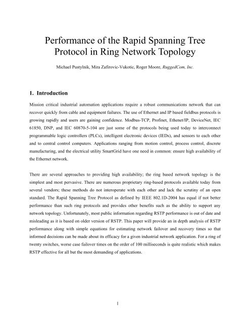
<strong>Performance</strong> <strong>of</strong> <strong>the</strong> Rapid Spann<strong>in</strong>g TreeProtocol <strong>in</strong> R<strong>in</strong>g Network TopologyMichael Pustylnik, Mira Zafirovic-Vukotic, Roger Moore, <strong>RuggedCom</strong>, Inc.1. IntroductionMission critical <strong>in</strong>dustrial automation applications require a robust communications network that canrecover quickly from cable and equipment failures. The use <strong>of</strong> E<strong>the</strong>rnet and IP based fieldbus <strong>protocol</strong>s isgrow<strong>in</strong>g <strong>rapid</strong>ly and users are ga<strong>in</strong><strong>in</strong>g confidence. Modbus-TCP, Pr<strong>of</strong><strong>in</strong>et, E<strong>the</strong>net/IP, DeviceNet, IEC61850, DNP, and IEC 60870-5-104 are just some <strong>of</strong> <strong>the</strong> <strong>protocol</strong>s be<strong>in</strong>g used today to <strong>in</strong>terconnectprogrammable logic controllers (PLCs), <strong>in</strong>telligent electronic devices (IEDs), and sensors to each o<strong>the</strong>rand to central control computers. Applications rang<strong>in</strong>g from motion control, process control, discretemanufactur<strong>in</strong>g, and <strong>the</strong> electrical utility SmartGrid have one need <strong>in</strong> common: ensure high availability <strong>of</strong><strong>the</strong> E<strong>the</strong>rnet network.There are several approaches to provid<strong>in</strong>g high availability; <strong>the</strong> r<strong>in</strong>g based network topology is <strong>the</strong>simplest and most pervasive. There are numerous proprietary r<strong>in</strong>g-based <strong>protocol</strong>s available today fromseveral vendors; <strong>the</strong>se methods do not <strong>in</strong>teroperate with each o<strong>the</strong>r and lack <strong>the</strong> scrut<strong>in</strong>y <strong>of</strong> an openstandard. The Rapid Spann<strong>in</strong>g Tree Protocol as def<strong>in</strong>ed by IEEE 802.1D-2004 has equal if not betterperformance than such r<strong>in</strong>g <strong>protocol</strong>s and provides o<strong>the</strong>r benefits such as <strong>the</strong> ability to support anynetwork topology. Unfortunately, most public <strong>in</strong>formation regard<strong>in</strong>g RSTP performance is out <strong>of</strong> date andmislead<strong>in</strong>g as it is based on older version <strong>of</strong> RSTP. This paper will provide an <strong>in</strong> depth analysis <strong>of</strong> RSTPperformance along with simple equations for estimat<strong>in</strong>g network failover and recovery times so that<strong>in</strong>formed decisions can be made about its efficacy for a given <strong>in</strong>dustrial network application. For a r<strong>in</strong>g <strong>of</strong>twenty switches, worse case failover times on <strong>the</strong> order <strong>of</strong> 100 milliseconds is quite realistic which makesRSTP effective for all but <strong>the</strong> most demand<strong>in</strong>g <strong>of</strong> applications.1
Bridge Diameter: The maximum number <strong>of</strong> switches between any two end stations.Root Port: The port that <strong>of</strong>fers <strong>the</strong> lowest cost path to <strong>the</strong> root bridge.Designated Port: The port that propagates Root <strong>in</strong>formation to <strong>the</strong> attached network segment.Alternate Port: The port that <strong>of</strong>fers <strong>the</strong> next best cost path to <strong>the</strong> root bridge and will become Root Port,if <strong>the</strong> current Root Port loses connectivity with <strong>the</strong> root bridge.Discard<strong>in</strong>g port state: The state <strong>in</strong> which <strong>the</strong> port is only send<strong>in</strong>g and receiv<strong>in</strong>g STP BPDUs whileblock<strong>in</strong>g any regular network traffic.Forward<strong>in</strong>g port state: The state <strong>in</strong> which <strong>the</strong> port is send<strong>in</strong>g and receiv<strong>in</strong>g both STP BPDUs and regularnetwork traffic.2.2.2 RSTP – IEEE 802.1w [2]The STP <strong>protocol</strong> was first published <strong>in</strong> <strong>the</strong> IEEE 802.1D-1990 standard and has proven to be a reliablemethod for provid<strong>in</strong>g path redundancy while elim<strong>in</strong>at<strong>in</strong>g loops. However, STP was not orig<strong>in</strong>allydesigned for speed; when a l<strong>in</strong>k fails or a failed l<strong>in</strong>k returns to service, STP requires at least 30 seconds torestore network connectivity. RSTP is an evolution <strong>of</strong> STP. It was <strong>in</strong>troduced <strong>in</strong> <strong>the</strong> standard extensionIEEE 802.1w, and provides for faster <strong>spann<strong>in</strong>g</strong> <strong>tree</strong> convergence after a topology change. The 802.1Dterm<strong>in</strong>ology rema<strong>in</strong>ed primarily <strong>the</strong> same, and most parameters have been left unchanged. However,RSTP uses several new concepts:Tak<strong>in</strong>g advantage <strong>of</strong> a physical l<strong>in</strong>k failure/recovery detection: While STP was passively wait<strong>in</strong>g for atimer to expire to react to a change <strong>in</strong> a l<strong>in</strong>k state, RSTP may act immediately upon a l<strong>in</strong>k failure/recoverydetection.Proposal-Agreement mechanism: This is a feedback mechanism that takes place between RSTPcompliantbridges. While STP was passively wait<strong>in</strong>g for <strong>the</strong> network to converge before turn<strong>in</strong>g a port<strong>in</strong>to <strong>the</strong> forward<strong>in</strong>g state, RSTP is able to actively confirm that a port can safely transition to forward<strong>in</strong>gwithout rely<strong>in</strong>g on any timer configuration. This leads to a faster convergence.Edge ports: All ports that have been configured as edge ports are placed <strong>in</strong> forward<strong>in</strong>g state withoutcheck<strong>in</strong>g for loops.The new enhanced mechanisms allow RSTP to reduce failover and recovery times to just a few seconds.3
2.2.3 Enhanced RSTP (eRSTP TM )Although RSTP <strong>of</strong>fered a significant performance improvement compared to <strong>the</strong> legacy STP, it still hadseveral weaknesses:1. Even <strong>the</strong> failover and recovery time <strong>of</strong> a few seconds was not good enough for mission critical<strong>in</strong>dustrial E<strong>the</strong>rnet applications2. RSTP doesn’t support LANs with a bridge diameter greater than 40<strong>RuggedCom</strong> Inc. developed an enhanced version <strong>of</strong> <strong>the</strong> RSTP algorithm referred to as eRSTP TM which isfully compatible with <strong>the</strong> IEEE 802.1w RSTP <strong>protocol</strong> while enhanc<strong>in</strong>g it <strong>in</strong> several aspects:‐ eRSTP TM reduces failover and recovery times to just a few milliseconds (5ms per a pair <strong>of</strong> bridges<strong>in</strong>volved <strong>in</strong> <strong>the</strong> topology change)‐ eRSTP TM is able to operate <strong>in</strong> larger LANs with a bridge diameter greater than 20Be<strong>in</strong>g a proprietary enhancement, <strong>the</strong> eRSTP TM algorithm was never published.2.2.4 RSTP – IEEE 802.1D-2004 [3]The IEEE Standard 802.1D-2004 edition is a very important step <strong>in</strong> <strong>the</strong> STP/RSTP evolution because it:‐ Obsoletes <strong>the</strong> legacy STP.‐ Addresses weaknesses <strong>of</strong> <strong>the</strong> IEEE 802.1w RSTP and def<strong>in</strong>es a significantly revised and highlyoptimized version <strong>of</strong> RSTP. The new RSTP provides for very short failover and recovery times(identical to those <strong>of</strong> eRSTP TM ).Although not adopted yet by most network<strong>in</strong>g equipment vendors, <strong>the</strong> optimized RSTP seems to exceed<strong>the</strong> performance <strong>of</strong> different proprietary solutions.NOTE: The <strong>RuggedCom</strong> eRSTP TM has been recently enhanced to <strong>in</strong>corporate <strong>the</strong> strengths <strong>of</strong> <strong>the</strong>optimized IEEE 802.1D-2004 RSTP, while still support<strong>in</strong>g 4 times longer bridge diameters than thosesupported by a standard implementation.4
3. Analytical Method for Calculat<strong>in</strong>g R<strong>in</strong>g Failover TimesRSTP is a complicated <strong>protocol</strong> as it allows for any network topology from a r<strong>in</strong>g to a full mesh.Analytical determ<strong>in</strong>ation <strong>of</strong> <strong>the</strong> failover and recovery performance for an arbitrary network and faultscenario is a non trivial exercise. However, a r<strong>in</strong>g topology is simple enough to perform such analysiswhich is detailed <strong>in</strong> <strong>the</strong> rest <strong>of</strong> section 3 and <strong>the</strong> f<strong>in</strong>al result is summarized here. The worst case r<strong>in</strong>gnetwork failover time <strong>in</strong> case <strong>of</strong> a s<strong>in</strong>gle l<strong>in</strong>k failure can be calculated us<strong>in</strong>g <strong>the</strong> follow<strong>in</strong>g formulae:where:NT LT PAT L + (N - 3)*T PA , if N is evenT L + (N - 2)*T PA , if N is odd- number <strong>of</strong> switches <strong>in</strong> <strong>the</strong> r<strong>in</strong>g- time required by a switch to detect a l<strong>in</strong>k failure- time required by a pair <strong>of</strong> switches to perform RSTP Proposal-Agreement handshak<strong>in</strong>g;equal to <strong>the</strong> sum <strong>of</strong> <strong>the</strong> BPDU process<strong>in</strong>g times <strong>in</strong> both switches <strong>of</strong> <strong>the</strong> pair.The worst case failover time <strong>in</strong> case <strong>of</strong> a root bridge failure can be calculated us<strong>in</strong>g <strong>the</strong> formulae:T L + (2*N - 5)*T PA , if N is evenT L + (2*N - 4)*T PA , if N is oddHowever, <strong>the</strong> worst root bridge failure case can be easily avoided by adjust<strong>in</strong>g some RSTP managementparameters and thus <strong>the</strong> failover time can be reduced to a value identical to that <strong>of</strong> <strong>the</strong> s<strong>in</strong>gle l<strong>in</strong>k failurecase.T L and T PA values may differ from vendor to vendor, from product to product, and for different porttypes. For <strong>RuggedCom</strong> products, <strong>the</strong>se values are:T PAT L= 5ms= 4-6ms for 100Base-TX and 100Base-FX l<strong>in</strong>ks= 20ms for 1000Base-X l<strong>in</strong>ks= 700ms for 1000Base-T l<strong>in</strong>ks (def<strong>in</strong>ed by <strong>the</strong> IEEE Standard 802.3)5
3.1 Symbols and AssumptionsThe symbol legend def<strong>in</strong>ed <strong>in</strong> <strong>the</strong> IEEE 802.1D standard will be used <strong>in</strong> network diagrams to helpillustrate <strong>the</strong> state transition changes <strong>in</strong>curred by RSTP dur<strong>in</strong>g a topology change.Port Role Port State Legend Transmitted BPDU LegendForward<strong>in</strong>gDesignated ProposalDesignatedDiscard<strong>in</strong>gRoot AgreementRoot Forward<strong>in</strong>g Root with TCTCAlternateDiscard<strong>in</strong>gFor <strong>the</strong> matter <strong>of</strong> our analysis we use <strong>the</strong> follow<strong>in</strong>g assumptions:1. The r<strong>in</strong>g conta<strong>in</strong>s an even number <strong>of</strong> switches N = n*2. Derivation <strong>of</strong> <strong>the</strong> formulas for an odd number<strong>of</strong> switches is very similar and, <strong>the</strong>refore, is omitted.2. L<strong>in</strong>ks are not longer than a few kilometers, so BPDU frame propagation time on <strong>the</strong> wire can becompletely ignored.A time variable T TC is used <strong>in</strong> <strong>the</strong> analysis. It is <strong>the</strong> time required by a pair <strong>of</strong> switches to deliver aTopology Change notification from one switch to ano<strong>the</strong>r. As BPDU carry<strong>in</strong>g a Topology Changenotification is only propagat<strong>in</strong>g <strong>in</strong> one direction and no handshak<strong>in</strong>g is <strong>in</strong>volved, T TC is roughly half <strong>of</strong>T PA .3.2 Derivation <strong>of</strong> a S<strong>in</strong>gle L<strong>in</strong>k Failover TimeFigure 1 shows a simple r<strong>in</strong>g network with all l<strong>in</strong>ks <strong>in</strong>tact <strong>in</strong> a steady state condition; switch S 0 is <strong>the</strong> rootbridge and switch S n has one port <strong>in</strong> <strong>the</strong> discard<strong>in</strong>g state. In order to determ<strong>in</strong>e <strong>the</strong> worst case one shouldperform <strong>the</strong> analysis for each possible l<strong>in</strong>k failure <strong>in</strong> <strong>the</strong> r<strong>in</strong>g. Perform<strong>in</strong>g <strong>the</strong> analysis on all possible l<strong>in</strong>kswould show that <strong>the</strong> worst case is: <strong>the</strong> failed l<strong>in</strong>k is <strong>the</strong> one fur<strong>the</strong>st from <strong>the</strong> switch with an Alternateport; <strong>in</strong> this case, it is <strong>the</strong> l<strong>in</strong>k between S 0 and S 1 . Similarly, <strong>the</strong> “best” case would be <strong>the</strong> l<strong>in</strong>k between S (n-1) and S n . The worst case scenario <strong>in</strong>volves <strong>the</strong> maximum number <strong>of</strong> switches required for propagat<strong>in</strong>gand negotiat<strong>in</strong>g RSTP <strong>in</strong>formation around <strong>the</strong> r<strong>in</strong>g.6
After <strong>the</strong> l<strong>in</strong>k failure, <strong>the</strong> r<strong>in</strong>g is divided <strong>in</strong>to two segments S 0 -S -(n-1) and S 1 -S n because connectivitybetween <strong>the</strong>m is blocked by <strong>the</strong> S n ’s Alternate port S n -S -(n-1) . (Figure 2)Traffic sourceTraffic dest<strong>in</strong>ationS 0S 0S -1Root BridgeS 1S -1S 1S -2. . .S -(n-2)S -(n-1)S (n-2)S 2AlternatePortS (n-1)S n. . .S -2. . . . . .S -(n-2)S -(n-1)S (n-2)S 2S (n-1)S nFigure 1:Steady state before l<strong>in</strong>k failureFigure 2.R<strong>in</strong>g segments after l<strong>in</strong>k failureThe follow<strong>in</strong>g activities are required to restore <strong>the</strong> r<strong>in</strong>g connectivity – note that <strong>the</strong> activities are differentfor <strong>the</strong> two segments:• Segment S 0 -S -(n-1) does not require any topology reconfiguration because <strong>the</strong> old path to <strong>the</strong> Root isstill valid for all switches <strong>in</strong> that segment.• Switch S n must change its former Alternate port role to Root and its former Root port to Designated;all o<strong>the</strong>r switches <strong>in</strong> segment S 1 -S n should swap <strong>the</strong>ir Designated and Root port roles.• Switch S n must <strong>in</strong>itiate a Topology Change notification which must be propagated from S n up to S 0 sothat S 0 will flush its MAC address table on <strong>the</strong> failed l<strong>in</strong>k S 0 -S 1 .Table 1 describes how <strong>the</strong> above activities will proceed at different time po<strong>in</strong>ts.7
Table 1. Time-l<strong>in</strong>e <strong>of</strong> RSTP actions by different switches <strong>in</strong> <strong>the</strong> r<strong>in</strong>g (s<strong>in</strong>gle l<strong>in</strong>k failure)TimeS 0Switchact<strong>in</strong>gAction DescriptionS 0 doesn’t do anyth<strong>in</strong>g because it is <strong>the</strong> Root.FigureS 1 detects <strong>the</strong> l<strong>in</strong>k failure and immediately ages out itsT LS 1Root <strong>in</strong>fo on port S 1 -S 0 . S 1 -S 0 is S 1 ’s only path to <strong>the</strong>Root, so S 1 will declare itself as a new root bridge andFigure 3T L + T PA S 2… {S 3 ,…,S n-2 }start Proposal-Agreement handshak<strong>in</strong>g with S 2 .New Root <strong>in</strong>formation comes to S 2 from its only pathto <strong>the</strong> previous Root, so S 2 replaces <strong>the</strong> previous Root<strong>in</strong>fo with <strong>the</strong> new one, puts S 2 -S 3 to Discard<strong>in</strong>g state,sends Agreement BPDU to S 1 and starts Proposal-Agreement handshak<strong>in</strong>g with S 3 .In a similar fashion, <strong>the</strong> Proposal-Agreementhandshak<strong>in</strong>g will occur on each hop up to S (n-1) .Figure 4-T L + (n-2)*T PA S n-1 {S 1 ,…,S n-1 }all agree about recogniz<strong>in</strong>g S 1 as Root. Figure 5T L + (n-2+1)*T PA S n-1… {S n-2 ,…,S 2 }T L + (n-2+1)*T PA + (n-2)*T PA S 1T L + (n-2+1)*T PA + (n-1)*T TC S 0S nSuccessful Proposal-Agreement cont<strong>in</strong>ues until S n isreached. As S n has a better Root (S 0 ) <strong>in</strong>formation, itturn its Alternate Port <strong>in</strong>to Root Port and reply with itsown Proposal ra<strong>the</strong>r than Agreement. NOTE: Whenchang<strong>in</strong>g <strong>the</strong> former Alternate port role to Root <strong>the</strong>switch will put that port to forward<strong>in</strong>g and send aTopology Change notification to S -(n-1) .S n-1 starts Proposal-Agreement handshak<strong>in</strong>g with S n-2 .Also, approximately at this time Topology Changenotification also reaches S -(n-1) .The Proposal-Agreement handshak<strong>in</strong>g occurs on eachhop back to S 1 (and <strong>the</strong> Topology Change notificationpropagates to S 0 ).All switches agree about <strong>the</strong> new path to <strong>the</strong> Root (S 0 )and all ports are <strong>in</strong> Forward<strong>in</strong>g state.Topology Change Notification reaches S 0 and causesit to flush its MAC address table on port S 0 -S 1 (this is<strong>the</strong> purpose <strong>of</strong> TCN). Network connectivity restored.Figure 6--Figure 7Figure 88
S 0S 0S -1S 1S -1S 1S -2. . . . . .S -(n-2)S -(n-1)S (n-2)S 2S (n-1)S nS -2. . . . . .S -(n-2)S -(n-1)S (n-2)S 2S (n-1)S nFigure 3. Figure 4.S 1 declares itself as new RootS 2 agrees about S 1 be<strong>in</strong>g RootS 0S -1S 1S -2S 2S 0S -1S -2S -(n-1). . . . . .S -(n-2)S (n-2)S -(N-2)S (n-2)S (n-1)S -(n-1)S (n-1)Sn. . . . . .TCS 1S nS 2Figure 5.{S 1 ,…,S (n-1) } all agree about S 1 be<strong>in</strong>g RootFigure 6.S n turns its Alternate Port <strong>in</strong>to Root Port andreplies with proper Root (S 0 ) <strong>in</strong>formation9
Traffic sourceTraffic dest<strong>in</strong>ationS 0S 0S -1S 1S -1Root BridgeS 1S -2. . . . . .S -(N-2)S -(n-1)S (n-2)S 2S (n-1)S nFigure 7.All switches agree about newRoot pathS -2. . . . . .S -(n-2)S -(n-1)S 2S (n-1)S nFigure 8.Steady state after network recoveryS (n-2)So <strong>the</strong> overall failover time isT L + (n-2+1)*T PA + max( (n-1)*T TC , (n-2)*T PA )As we expla<strong>in</strong>ed above, T PA is significantly longer than T TC , and <strong>the</strong>n <strong>the</strong> overall failover time isT L + (n-2+1+n-2)*T PA = T L + (2*n-3)*T PA = T L + (N-3)*T PA3.3 Derivation <strong>of</strong> a Root Bridge Failover TimeFailure <strong>of</strong> <strong>the</strong> root bridge requires elect<strong>in</strong>g a new root bridge which adds fur<strong>the</strong>r complexity compared to<strong>the</strong> s<strong>in</strong>gle l<strong>in</strong>k failure analysis. Figure 9 shows <strong>the</strong> network <strong>in</strong> steady state before <strong>the</strong> root bridge fails.After <strong>the</strong> root bridge failure, <strong>the</strong> r<strong>in</strong>g is divided <strong>in</strong>to two segments S -1 -S -(n-1) and S 1 -S n becauseconnectivity between <strong>the</strong>m is blocked by <strong>the</strong> S n ’s Alternate port S n -S -(n-1) . (Figure 10). Each switch canhave a different bridge priority configured. Determ<strong>in</strong><strong>in</strong>g <strong>the</strong> worst case failover time demands analyz<strong>in</strong>gall cases where <strong>the</strong> new bridge could become any one <strong>of</strong> <strong>the</strong> switches <strong>in</strong> <strong>the</strong> r<strong>in</strong>g. Repeat<strong>in</strong>g <strong>the</strong> analysisfor all switches would show that <strong>the</strong> worst case has S 1 and S- 1 becom<strong>in</strong>g <strong>the</strong> next best root candidates withS 1 tak<strong>in</strong>g precedence over S- 1 . Table 2 describes how RSTP will proceed at different po<strong>in</strong>ts <strong>in</strong> time for <strong>the</strong>worst case.10
Traffic sourceTraffic dest<strong>in</strong>ationS 0S 0S -2S -(n-2)S -1S -(n-1)Root Bridge. . . . . .S 2AlternatePortS (n-1)S nFigure 9.Steady state before root bridge failureS 1S (n-2)S -1S -2S 1. . . . . .S -(n-2)S (n-2)S -(n-1)S 2S (n-1)S nFigure 10.R<strong>in</strong>g segments after root bridge failureTable 2. Time-l<strong>in</strong>e <strong>of</strong> RSTP actions by different switches <strong>in</strong> <strong>the</strong> r<strong>in</strong>g (root bridge failure)TimeSwitchact<strong>in</strong>gT L S -1 and S 1…{S 2 ,…,S n-2 } and{S -2 ,…,S -(n-2) }Action DescriptionEach <strong>of</strong> S 1 and S -1 detects <strong>the</strong> l<strong>in</strong>k failure, agesout its Root <strong>in</strong>fo and advertises itself as a newroot bridge.Proposal-Agreement handshak<strong>in</strong>g occurs <strong>in</strong>parallel on each hop <strong>in</strong> two segments, up to S (n-1)and S -(n-1)FigureFigure 11-T L + (n-2)*T PAS n-1 andS -(n-1){S 1 ,…,S n-1 }all agree about S 1 be<strong>in</strong>g Root, while{S -1 ,…,S -(n-1) } agree about S -1 be<strong>in</strong>g Root.Figure 1211
T L + (n-2+1+1)*T PA S n-1… {S n-2 ,…,S 3 }T L + (n-2+1+1)*T PA + (n-3)*T PA S 2T L + (n-2+1+1)*T PA + (n-3)*T PA+ T PAS nS 1S 2… {S 3 ,…,S -2 }S n receives proposal BPDUs from S n-1 and S -(n-1)at virtually <strong>the</strong> same time. For <strong>the</strong> worst casescenario, we assume that <strong>the</strong> proposal from S n-1is received and processed first (as you will seebelow, this case causes certa<strong>in</strong> network“confusion” and thus requires more RSTPactions to resolve it).S<strong>in</strong>ce S n doesn’t have any <strong>in</strong>formation about <strong>the</strong>S 0 failure yet, it will change its old AlternatePort role to Root Port and “reject” <strong>the</strong> S n-1 ’sproposal by send<strong>in</strong>g its own proposal with betterbut actually obsolete <strong>in</strong>formation about S 0 . This<strong>in</strong>fo will “confuse” all { S n-1 ,…,S 1 } switches.Right after that, S n will process S -(n-1) ’s proposalabout S -1 as Root. As S n receives that proposalfrom its only path to <strong>the</strong> Root, it immediatelyages out <strong>the</strong> old Root <strong>in</strong>formation and startsProposal-Agreement handshak<strong>in</strong>g with S n-1aga<strong>in</strong> – this time propos<strong>in</strong>g S -1 as Root. The newProposal is now fix<strong>in</strong>g <strong>the</strong> “confusion” justcaused by <strong>the</strong> previous Proposal about S 0 .S n-1 starts Proposal-Agreement handshak<strong>in</strong>gwith S n-2 about S -1 as Root.The Proposal-Agreement handshak<strong>in</strong>g occurs oneach hop back to S 2 .All switches <strong>in</strong> <strong>the</strong> r<strong>in</strong>g except S 1 erroneouslyagree about S -1 be<strong>in</strong>g Root. S 2 sends Proposal toS 1 about S -1 as Root.Be<strong>in</strong>g a better Root candidate, S 1 responds withits own Proposal about itself as Root.F<strong>in</strong>al round <strong>of</strong> handshak<strong>in</strong>g starts from S 2towards S -1 – this time for <strong>the</strong> real best Rootcandidate S 1 .The Proposal-Agreement handshak<strong>in</strong>g occurs oneach hop all <strong>the</strong> way to S -1 .Figure 13Figure 14--Figure 15Figure 16--12
T L + (n-2+1+1)*T PA + (n-3)*T PA+ T PA + (2*n-3)*T PAS -1All switches <strong>in</strong> <strong>the</strong> network agree about S 1 be<strong>in</strong>gRoot and all ports are <strong>in</strong> Forward<strong>in</strong>g state.Connectivity is restored.Figure 17Note that <strong>in</strong> <strong>the</strong> analysis Topology Change notification was not even mentioned because it propagatesalong with <strong>the</strong> <strong>in</strong>itial round <strong>of</strong> handshak<strong>in</strong>g, i.e. much before <strong>the</strong> f<strong>in</strong>al topology is achieved.S 0S 0S -1S -2S 1. . . . . .S -(n-2)S (n-2)S -(n-1)S 2S (n-1)S nS -1S -2S 1. . . . . .S -(n-2)S (n-2)S -(n-1)Root=S-1S 2S (n-1)S nRoot=S1Figure 11.S 1 and S -1 declare <strong>the</strong>mselves as RootFigure 12.{S 1 ,…,S n-1 } agree about S 1 , while{S -1 ,…,S -(n-1) } agree about S -1S 0S 0S -1S -2S 1. . . . . .S -(n-2)S (n-2)S -(n-1)S 2S (n-1)S nFigure 13.Root=S0S -1S -2S 1. . . . . .S -(n-2)S (n-2)S -(n-1)Root=S- 1S 2S (n-1)S nFigure 14.Root=S-1 Root=S0Root=S0S n sends obsolete proposal about S 0be<strong>in</strong>g Root13S n sends new proposal about S -1be<strong>in</strong>g Root
S 0S 0S -1S -2S 1. . . . . .S -(n-2)S (n-2)S -(n-1)Root=S-1S 2S (n-1)S nS -1S -2S 1. . . . . .S -(n-2)S (n-2)S -(n-1)Root=S1S 2S (n-1)S nFigure 15.All switches except S 1 agree about S -1 be<strong>in</strong>gRootFigure 16.S 1 rejects proposal about S -1 and declaresitself as RootTraffic sourceTraffic dest<strong>in</strong>ationS -1S 1S -2. . . . . .S -(n-2)S -(n-1)S 2S (n-1)S nFigure 17.Steady state after network recoveryS (n-2)14
So <strong>the</strong> overall root bridge failover time isT L + (n-2+2)*T PA + (n-3)*T PA + T PA + (2*n-3)*T PA = T L + (4*n – 5)*T PA = T L + (2*N – 5)* T PAPlease note that <strong>the</strong> described scenario is an uncontrolled <strong>the</strong>oretical worst case. This extensive failovertime can be easily and significantly reduced by tak<strong>in</strong>g a controlled case approach. If S n ’s Bridge Priorityis configured <strong>in</strong> such a way that it is <strong>the</strong> best root bridge candidate after <strong>the</strong> failed S 0 , <strong>the</strong> scenario getsmuch simpler. Events <strong>in</strong> <strong>the</strong> network will proceed like <strong>in</strong> <strong>the</strong> uncontrolled case until <strong>the</strong> step <strong>in</strong> Figure 12,but <strong>in</strong> <strong>the</strong> Figure 13 step S n will advertise itself as a Root to both half-r<strong>in</strong>g segments, thus start<strong>in</strong>g a f<strong>in</strong>alround <strong>of</strong> handshak<strong>in</strong>g. So <strong>the</strong> failover time gets reduced toT L + (n-2+1)* T PA + (n-2)* T PA = T L + (2*n – 3)* T PA = T L + (N – 3)* T PA ,which is identical to <strong>the</strong> formula derived for <strong>the</strong> s<strong>in</strong>gle l<strong>in</strong>k failure case.3.4 L<strong>in</strong>k and Root Bridge RecoveryThe connectivity recovery mechanism <strong>in</strong> case <strong>of</strong> a l<strong>in</strong>k or root bridge recovery is different from <strong>the</strong> l<strong>in</strong>k orroot bridge failure case <strong>in</strong> <strong>the</strong> follow<strong>in</strong>g aspects:1. L<strong>in</strong>k detection time is not <strong>in</strong>cluded <strong>in</strong> <strong>the</strong> network outage time – RSTP activities only start after <strong>the</strong>l<strong>in</strong>k is detected2. All l<strong>in</strong>ks are available for <strong>the</strong> Root <strong>in</strong>formation propagation, so multiple “reconfiguration” <strong>of</strong> certa<strong>in</strong>network segments does not occurAs a result, network outage time <strong>in</strong> <strong>the</strong> case <strong>of</strong> a l<strong>in</strong>k or root bridge recovery is always shorter than <strong>in</strong> <strong>the</strong>case <strong>of</strong> a l<strong>in</strong>k or Root Ridge failure. S<strong>in</strong>ce only <strong>the</strong> worst case is <strong>of</strong> importance, l<strong>in</strong>k or root bridgerecovery case analysis is omitted.15
4. Extrapolation to Meshed NetworksAs meshed network topology analysis is more complex than that <strong>of</strong> a r<strong>in</strong>g, <strong>the</strong> first impression could bethat RSTP performance must be always worse <strong>in</strong> meshed topology compared to a s<strong>in</strong>gle r<strong>in</strong>g. However,that is not generally true although it is <strong>in</strong> some scenarios.4.1 S<strong>in</strong>gle L<strong>in</strong>k FailureA meshed network can be looked as a r<strong>in</strong>g network with some <strong>in</strong>ter-switch connections which result <strong>in</strong>shortcuts for BPDU propagation. Figure 18 presents a simplified example <strong>of</strong> this.Traffic sourceTraffic dest<strong>in</strong>ationS 0S -1Root BridgeS 1S -2Port. . . . . .S -(n-2)AlternateS -(n-1)S 2AlternatePortAlternatePortS (n-1)S nFigure 18.S (n-2)Analyz<strong>in</strong>g this network behavior <strong>in</strong> <strong>the</strong> same case <strong>of</strong> <strong>the</strong> l<strong>in</strong>k S 0 -S 1 failure, shows that RSTP handshak<strong>in</strong>gsteps don’t have to go all <strong>the</strong> way from S 1 to S n. Information about <strong>the</strong> root bridge (S 0 ) location canalready be obta<strong>in</strong>ed from <strong>the</strong> switch S (n-2) or S -2 which will make <strong>the</strong> network recovery faster. Anobservation can be made that meshed networks provide shorter paths for RSTP <strong>in</strong>formation propagationwhich allows handshak<strong>in</strong>g sequence to complete faster. As a result, a meshed network s<strong>in</strong>gle l<strong>in</strong>k failovertime should be same or better than <strong>the</strong> failover time <strong>of</strong> <strong>the</strong> largest outer r<strong>in</strong>g <strong>in</strong> that network topology(assum<strong>in</strong>g <strong>the</strong> given topology does have such an outer r<strong>in</strong>g).16
4.2 Root Bridge FailureUnfortunately, <strong>the</strong> additional complexity <strong>of</strong> meshed topology causes root bridge failure failover times to<strong>in</strong>crease compared with <strong>the</strong> simple r<strong>in</strong>g. The problem <strong>of</strong> <strong>the</strong> root bridge failure scenario is that, after <strong>the</strong>failure, every switch hold<strong>in</strong>g <strong>the</strong> obsolete Root <strong>in</strong>formation is feed<strong>in</strong>g it back to <strong>the</strong> network, thus“confus<strong>in</strong>g” all o<strong>the</strong>r switches and mak<strong>in</strong>g <strong>the</strong>m “reject” <strong>the</strong> right new Root <strong>in</strong>formation. The sameproblem exists <strong>in</strong> <strong>the</strong> r<strong>in</strong>g topology as well but, due to <strong>the</strong> topology simplicity, <strong>the</strong>re are no loops where<strong>the</strong> obsolete <strong>in</strong>formation would circulate and <strong>the</strong> “confusion” is fixed very quickly. This is not <strong>the</strong> case <strong>in</strong>meshed networks.A meshed network can be looked at as multiple smaller r<strong>in</strong>gs <strong>in</strong>terconnected with each o<strong>the</strong>r at multiplepo<strong>in</strong>ts. This topology allows <strong>the</strong> obsolete Root <strong>in</strong>formation to circulate multiple times back and forth<strong>in</strong>side and between <strong>the</strong> smaller r<strong>in</strong>gs. The network will not be confused forever - accord<strong>in</strong>g to <strong>the</strong> RSTPstandard, <strong>the</strong> old <strong>in</strong>formation will be aged out after it traverses <strong>the</strong> maximum allowed number <strong>of</strong> hops(normally 20). However, <strong>the</strong> network outage time can last as long as seconds. It is caused by <strong>the</strong> fact thatmultiple switches <strong>in</strong> <strong>the</strong> network are cont<strong>in</strong>uously busy with process<strong>in</strong>g and forward<strong>in</strong>g contradictoryBPDUs be<strong>in</strong>g cont<strong>in</strong>uously received on different ports.Root bridge failure <strong>in</strong> a meshed network is very hard to analyze and predict, and a result may be totallydifferent for every specific topology. The common conclusion is though, that <strong>the</strong> root bridge failover timegrows exponentially as more redundant paths are added to <strong>the</strong> network topology. The root bridge failure<strong>in</strong> meshed topology is a well recognized problem. Although some proprietary mechanisms are <strong>of</strong>fered to<strong>in</strong>directly improve <strong>the</strong> RSTP performance, no common solution is known for this case. This is <strong>the</strong> pricepaid for <strong>the</strong> high level <strong>of</strong> l<strong>in</strong>k redundancy provided by meshed network topology.17
5. Empirical <strong>Performance</strong> DataTo corroborate <strong>the</strong> RSTP analysis, test<strong>in</strong>g <strong>of</strong> failover performance was done on a test network. The sameworst case setup is used on r<strong>in</strong>g networks with 4 to 40 switches as illustrated <strong>in</strong> Figures 1 and 9. Thenetwork consists <strong>of</strong> RuggedSwitch TM RS900 and RSG2100 switches <strong>in</strong>terconnected with 100Base-TXl<strong>in</strong>ks. The switches were us<strong>in</strong>g <strong>the</strong> Rugged Operat<strong>in</strong>g System (ROS TM ) v3.4 operat<strong>in</strong>g system that has anIEEE 802.1D-2004 RSTP implementation. A SmartBits E<strong>the</strong>rnet packet blaster was used to generate highrates <strong>of</strong> traffic and determ<strong>in</strong>e <strong>the</strong> number <strong>of</strong> dropped frames dur<strong>in</strong>g <strong>the</strong> failover event. 45Mbpsunidirectional traffic was generated. No o<strong>the</strong>r application was runn<strong>in</strong>g on <strong>the</strong> network. The switches wereconfigured <strong>in</strong> such way that MAC address tables are not purged by l<strong>in</strong>k loss, mak<strong>in</strong>g <strong>the</strong> measuredfailover times due to RSTP only.Failover performance was measured for <strong>the</strong> worst case l<strong>in</strong>k failure and root bridge failure. L<strong>in</strong>k failurewas accomplished by simply disconnect<strong>in</strong>g <strong>the</strong> cable while root bridge failure was done by power<strong>in</strong>g <strong>of</strong>f<strong>the</strong> switch. The failover time was calculated by multiply<strong>in</strong>g <strong>the</strong> number <strong>of</strong> dropped packets (determ<strong>in</strong>edby <strong>the</strong> SmartBits) by <strong>the</strong> time between start <strong>of</strong> transmission <strong>of</strong> two consecutive messages (which is aconstant). The measured and analytical failover times are shown <strong>in</strong> Figure 19 and Table 3.[ms]RSTP Failover Times if L<strong>in</strong>k Fails20015010050Failover TimeMeasuredTheoretical UpperBound00 10 20 30 40Number <strong>of</strong> SwitchesFigure 19. Measured vs. <strong>the</strong>oretical RSTP failover time <strong>in</strong> r<strong>in</strong>g network if s<strong>in</strong>gle l<strong>in</strong>k fails.18
The measured failover times <strong>in</strong> case <strong>of</strong> a l<strong>in</strong>k failure are smaller than <strong>the</strong> <strong>the</strong>oretical upper bound that isanalytically derived <strong>in</strong> Section 3.2 which is a result <strong>of</strong> somewhat conservative choices for <strong>the</strong> failoverequation constants. Measur<strong>in</strong>g <strong>the</strong> slope <strong>of</strong> <strong>the</strong> measured failover times yields T P =2.1ms to give moreaccurate results from <strong>the</strong> failover equation. However, it is prudent to use <strong>the</strong> more conservative timeconstants for any network plann<strong>in</strong>g activities.Table 3. Measured vs. <strong>the</strong>oretical RSTP failover time <strong>in</strong> r<strong>in</strong>g network if <strong>the</strong> root bridge fails.Number <strong>of</strong>Switches <strong>in</strong> R<strong>in</strong>gMeasured FailoverTime [ms]Theoretical UpperBound [ms]40 93.50 38139 142.53 37636 244.69 34135 124.53 33630 67.59 28129 100.31 27626 59.85 24125 89.71 236The measured failover times <strong>in</strong> case <strong>of</strong> <strong>the</strong> root bridge failure are smaller than <strong>the</strong> <strong>the</strong>oretical upper bound<strong>of</strong> Section 3.3. However, <strong>the</strong> measured values show significant randomness, with no apparent l<strong>in</strong>ear<strong>in</strong>crease <strong>in</strong> failover times, while <strong>the</strong> correspond<strong>in</strong>g <strong>the</strong>oretical upper bound is l<strong>in</strong>ear. This can beexpla<strong>in</strong>ed by <strong>the</strong> significant randomness <strong>of</strong> <strong>the</strong> events that contribute to <strong>the</strong> actual sequence <strong>of</strong> RSTP<strong>protocol</strong> state mach<strong>in</strong>e events for <strong>the</strong> root bridge failure scenario.6. Comparison <strong>of</strong> STP, RSTP and eRSTP with Proprietary Solutions.For many years, <strong>the</strong>re was no standard redundant LAN solution that would provide short networkrecovery times sufficient for Industrial E<strong>the</strong>rnet applications. As a result, some network<strong>in</strong>g equipmentvendors <strong>of</strong>fered different proprietary <strong>protocol</strong>s designed to solve <strong>the</strong> problem for r<strong>in</strong>g network topology.The table on <strong>the</strong> next page compares some <strong>of</strong> such proprietary solutions with STP/RSTP and with eacho<strong>the</strong>r.19
ProtocolVendorCan be used <strong>in</strong>multi-vendorenvironmentMax BridgeDiameterTopologyS<strong>in</strong>gle r<strong>in</strong>g l<strong>in</strong>k failover time(for different number <strong>of</strong>switches)10 15 20STP IEEE Standard Yes 40 Any >30sRSTP (802.1w) IEEE Standard Yes 40 Any Several secondsHiPER R<strong>in</strong>g [4],[5] Hirschmann NoVirtually200-500ms, <strong>in</strong>dependent <strong>of</strong>R<strong>in</strong>gunlimitednumber <strong>of</strong> switchesTurbo R<strong>in</strong>g [4],[6] Moxa NoVirtuallyunlimitedR<strong>in</strong>g
7. ConclusionRSTP performance is both predictable and repeatable for failure and recovery <strong>of</strong> switches and cabl<strong>in</strong>g <strong>in</strong> ar<strong>in</strong>g topology. Precise equations can be used to determ<strong>in</strong>e <strong>the</strong> network outage time; for a r<strong>in</strong>g <strong>of</strong> twentyswitches, worse case failover times on <strong>the</strong> order <strong>of</strong> 100 milliseconds are quite realistic - typical RSTPperformance is much better. Unfortunately, most literature to date states RSTP failover performance <strong>of</strong>several seconds based on results from <strong>the</strong> older IEEE 802.1w RSTP. The analysis <strong>in</strong> this paper hopefullywill put this misconception to rest and give confidence to designers <strong>of</strong> such networks; RSTP is more thancapable <strong>of</strong> be<strong>in</strong>g deployed <strong>in</strong> very demand<strong>in</strong>g automation networks.RSTP has o<strong>the</strong>r advantages over <strong>the</strong> ‘r<strong>in</strong>g’ <strong>protocol</strong>s such as <strong>the</strong> ability to support any network topology<strong>in</strong>clud<strong>in</strong>g mesh which allows for an even greater degree <strong>of</strong> redundancy. RSTP tends to have faster notslower network recovery times. RSTP works <strong>in</strong> a multi-vendor environment and is supported by all <strong>the</strong>major switch vendors. F<strong>in</strong>ally, RSTP was created by and is supported by an <strong>in</strong>ternational standardsorganization which ensures scrut<strong>in</strong>y by peers and future harmony with <strong>the</strong> myriad <strong>of</strong> o<strong>the</strong>r E<strong>the</strong>rnetstandards under development. RSTP is an excellent solution for many mission critical <strong>in</strong>dustrial E<strong>the</strong>rnetapplications which is why it has seen so much success to date and why it will cont<strong>in</strong>ue to be <strong>the</strong> dom<strong>in</strong>antE<strong>the</strong>rnet redundancy <strong>protocol</strong> <strong>in</strong> <strong>the</strong> future.8. References[1] ANSI/IEEE Std 802.1D, 1998 Edition[2] ANSI/IEEE Std 802.1w, 2001 Edition[3] ANSI/IEEE Std 802.1D, 2004 Edition[4] “High Availability Networks”, The Industrial E<strong>the</strong>rnet Book,[5] M. Schaub, H. Kell, “Redundancy Process with Hirschmann Switches”, ComConsultKommunikationstechnik GmbH, 2003,[6] “Stay Connected with Turbo R<strong>in</strong>g”, Moxa Technologies, Inc.,[7] “RapidR<strong>in</strong>g TM – Redundancy from Contemporary Controls”, Contemporary Control Systems, Inc.,2004[8] “Secure Web Management User Guide for Magnum 6K family <strong>of</strong> Switches, Release 3.6”,GarrettCom, Inc.21
9. BiographiesMichael Pustylnik is a senior s<strong>of</strong>tware eng<strong>in</strong>eer and project leader for <strong>RuggedCom</strong>, Inc., a lead<strong>in</strong>gmanufacturer <strong>of</strong> <strong>in</strong>dustrially hardened communications technology for mission-critical applications <strong>in</strong>harsh environments. Michael has over 10 years <strong>of</strong> experience <strong>in</strong> develop<strong>in</strong>g embedded s<strong>of</strong>tware forwireless and wired communications. Prior to jo<strong>in</strong><strong>in</strong>g <strong>RuggedCom</strong> Michael was a s<strong>of</strong>tware project leaderfor Motorola Communications division where he developed mobile and portable wireless communicationequipment. Michael graduated from <strong>the</strong> Technion - Israel Institute <strong>of</strong> Technology <strong>in</strong> 1994 with a Bachelor<strong>of</strong> Electrical Eng<strong>in</strong>eer<strong>in</strong>g degree major<strong>in</strong>g <strong>in</strong> communications.Mira Zafirovic-Vukotic is a quality manager <strong>of</strong> <strong>RuggedCom</strong> Inc. Mira has over 20 years experience<strong>in</strong> communication <strong>protocol</strong>s, performance analysis, system verification, security and control systems. Herprevious employers were M. Pup<strong>in</strong> Institute from Belgrade, and Agilent Technologies. Mira hasgraduated from University <strong>of</strong> Belgrade, Faculty <strong>of</strong> Ma<strong>the</strong>matics, major <strong>in</strong> computer science, <strong>in</strong> 1981 andobta<strong>in</strong>ed PhD <strong>in</strong> technical sciences from University <strong>of</strong> Twente, <strong>the</strong> Ne<strong>the</strong>rlands <strong>in</strong> 1988. Mira hasauthored 6 IEEE/ACM journal papers related to communication systems. She is a senior member <strong>of</strong> IEEEand member <strong>of</strong> IEC TC57 WG15.Roger Moore is <strong>the</strong> Eng<strong>in</strong>eer<strong>in</strong>g Vice President <strong>of</strong> <strong>RuggedCom</strong>, Inc. Prior to found<strong>in</strong>g <strong>RuggedCom</strong>,Roger was a project manager for General Electric’s Power Management division where he developedadvanced protective relay<strong>in</strong>g systems and substation automation technology. Roger graduated from <strong>the</strong>University <strong>of</strong> Toronto <strong>in</strong> 1990 with a Bachelor <strong>of</strong> Applied Science degree major<strong>in</strong>g <strong>in</strong> computer scienceand physics. He holds patents related to advances <strong>in</strong> communications and protective relay<strong>in</strong>g technology.He is also an active member <strong>of</strong> <strong>the</strong> IEEE and is <strong>in</strong>volved <strong>in</strong> develop<strong>in</strong>g <strong>the</strong> new IEEE 1588 standard forprecision time synchronization <strong>of</strong> devices via a communications network.22