Self Balancing Robot Using Android Phone - IRNet Explore
Self Balancing Robot Using Android Phone - IRNet Explore
Self Balancing Robot Using Android Phone - IRNet Explore

Create successful ePaper yourself
Turn your PDF publications into a flip-book with our unique Google optimized e-Paper software.
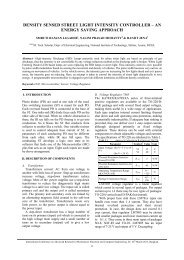
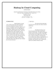
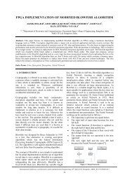
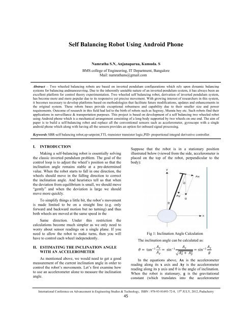
<strong>Self</strong> <strong>Balancing</strong> <strong>Robot</strong> <strong>Using</strong> <strong>Android</strong> <strong>Phone</strong>Namratha S.N, Anjanaparua, Kumuda. SBMS college of Engineering, IT Department, BangaloreMail: namrathans@gmail.comAbstract – Two wheeled balancing robots are based on inverted pendulum configurations which rely upon dynamic balancingsystems for balancing andmanoeuvring. Due to the inherently unstable nature of an inverted pendulum system, it has always been anexcellent platform for control theory experimentation. Two wheeled self balancing robot, derivation of inverted pendulum system,has become more and more popular due to its responsive yet precise movement. With growing interest of researchers in this system,it becomes necessary to develop platforms based on methodologies that facilitate future modifications, updates and enhancements inthe original system. These robots bases provide exceptional robustness and capability due to their smaller size and powerrequirements. Outcome of research in this field had led to the birth of robots such as Segway, Murata boy etc. Such robots find theirapplications in surveillance & transportation purposes. This project is based on development of a self balancing two wheeled robotusing <strong>Android</strong> phone which is a mechanical arrangement consisting of a long body supported by two wheels on one end. The aim ofpaper is to build a self-balancing robot and replace all the conventional sensors such as accelerometer, gyroscope with a singleandroid phone which along with having all the sensors provides an option for onboard signal processing.Keywords:SBR-self balancing robot,sp-setpoint,TTL-transistor transistor logic,PID- proportional integral derivative controller.I. INTRODUCTIONMaking a self-balancing robot is essentially solvingthe classic inverted pendulum problem. The goal of thecontrol loop is to adjust the wheel’s position so that theinclination angle remains stable at a pre-determinedvalue. When the robot starts to fall in one direction, thewheels should move in the falling direction to correctthe inclination angle. And heuristics tell us that whenthe deviation from equilibrium is small, we should move“gently” and when the deviation is large we shouldmove more quickly.To simplify things a little bit, the robot’s movementis made limited to be on a straight line (e.g. onlyforward and backward motion but no turning) and thusboth wheels are moved at the same speed in theSame direction. Under this restriction thecalculations become much simpler as we only need toworry about sensor readings on a single plane. If youneed to allow the robot to make turns, then you willhave to control each wheel independently.II. ESTIMATING THE INCLINATION ANGLEWITH AN ACCELEROMETERAs mentioned above, we would need to get a goodmeasurement of the current inclination angle in order tocontrol the robot’s movements. Let’s first examine howto use an accelerometer alone to measure the inclinationangle.Suppose that the robot is in a stationary positionillustrated below (viewed from the side, accelerometer isplaced on the top of the robot, perpendicular to thebody):Fig 1: Inclination Angle CalculationThe inclination angle can be calculated as: tan sin sin In the equations above, Ax is the accelerometerreading along its x axis and Ay is the accelerometerreading along its y axis and θ is the angle of inclination.When the robot is stationary, g is the gravitationalconstant (which translates into the accelerometerInternational Conference on Advancement in Engineering Studies & Technology, ISBN : 978-93-81693-72-8, 15 th JULY, 2012, Puducherry45
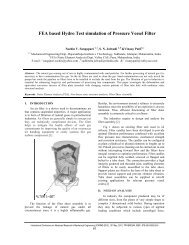
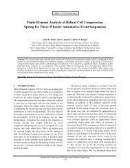
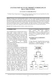
<strong>Self</strong> <strong>Balancing</strong> <strong>Robot</strong> <strong>Using</strong> <strong>Android</strong> <strong>Phone</strong>reading on they axis whenthe accelerometer is lyingflat). In this inverted pendulum application, we are onlyinterested in calculations where the inclination angle issmall since our goal is to ensure that the deviation fromequilibrium (typically equilibrium is reached when theinclination angle is close to 0 depending on the weightdistribution ofthe robot) is as small as possible. So wecan further simply the above equation for smallinclination angles:By only measuring the x axis reading of theaccelerometer we can get a rough estimate of theinclination angle. Of course, this isunder theassumption that the robot is standing still. In reality,when the robot is not in balance it will acceleratetowards the direction itis falling and thus the x axisreading of theaccelerometerr will be slightless than Axdue to the acceleration. At the same time, the y axisreading will be slightly more than the reading instandstill condition (Ay). As a result, the combinedvector will deviate from g. But when the accelerometeris placed nearthe center of gravity of the robot, theacceleration along the x axis is small in near-equilibriumconditions. Sothe above equation will exhibit somesmall error, but it remains a good approximation of theinclination angle.Accelerometer tends tobe very sensitive to theaccelerations introduced dueto movement or vibrationand thus the sensor readingswill contain some level ofnoise, which cannot be removed easily. So by relying onaccelerometer readings alone, we cannot get a reliableinclination angle estimate.III. ESTIMATING THE NCLINATIONN ANGLEWITH A GYROSCOPEGyroscope can measure the rate at which therotation is taking place. And the rotationangle for agiven time interval is governed by:Where G( (t) is the gyroscope reading with respect tothe rotation direction and θ(t) is the angle of inclination.When the time interval is small enough, the gyroscopereading can betreated as a constant and thus the aboveequation can be approximated as:Unlike the accelerometer, gyroscope measurementis largely immune to none angular movement and thusfar less susceptible to vibrations and laterall accelerationsmentionedpreviously. Butsince the angularmeasurement is cumulative, any minute error inmeasurements will manifest over time which causes theestimated angle to deviate from thetrue value. This isthe so called driftingeffect. Thus gyroscope alonecannot be used to reliably measure the inclination angleeither.Fig 2:Sensor FusionFromthe above diagram, we cansee that in order tomake the accelerometer readings more reliable, thereadingsare passed through a low pass filter (e.g.averaging over time) to smooth out any sudden changein values. And the gyroscope readings are integrated andthen added to the previous estimate to give the currentinclination angle reading. Each ofthe component isweightedand then added togetherto give the finalestimate. Mathematically, the estimated angle can beexpressed as follows:Where G is the gyroscope reading and angle Ax isthe angle calculated from the accelerometer reading inequation(1) above.Theweights are chosen such that the gyroscopedrift canbe corrected reasonably fast while the transienterrors inaccelerometer measurements do not cause theestimates to vary too much from iteration to iteration.These parameters are sensitive to the sampling periodbut as a rule of thumb, gyroscope readings should begiven a much higher weight (e.g. >0.9) since they areless noise-prone and accelerometer readings should begiven a lower weight (e.g.
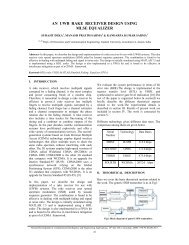
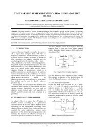
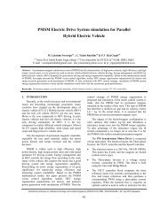
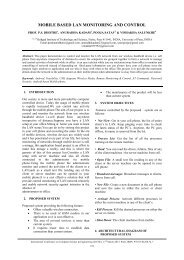
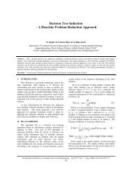
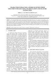
<strong>Self</strong> <strong>Balancing</strong> <strong>Robot</strong> <strong>Using</strong> <strong>Android</strong> <strong>Phone</strong>systems – a PID is the most commonly used feedbackcontroller. Controllers calculate an "error"" value as thedifference between a measured process variable and adesired setpoint. The controller attempts tominimize theerror by adjusting the process control inputs.The PIDcontroller calculation involves threeseparate constant parameters, and is accordinglysometimes called three-term control:the proportional,the integral and derivativee values,denoted P, I, and D. Heuristically, these values can beinterpreted in terms of time: P depends onthe present error, I on the accumulation of past errors,and D is a prediction of future errors, based on currentrate of change. The weightedsum of thesee three actionsis used to adjust the processs via a control element suchas the positionof a control valve, or the power suppliedto a heating element.In the absence of knowledge of the underlyingprocess, a PID controller has historically beenconsidered to be the best controller. By tuning the threeparameters inthe PID controller algorithm, thecontroller canprovide control action designed forspecific process requirements.Some applications mayrequire usingonly one ortwo actions toprovide the appropriate system control.This is achieved by setting the other parameters to zero.A PID controller will be called a PI, PD, P or Icontroller in the absence of the respective controlactions. PI controllers are fairly common, sincederivative action is sensitive to measurement noise,whereas the absence of anintegral mayprevent thesystem from reaching its target value due to the controlaction.Where:Fig 3:PID Controller: Proportional gain, a tuning parameter: Integral gain, a tuning parameter: Derivative gain, a tuning parameter: Error: Time or instantaneous time (the present)V. MAIN BLOCK DIAGRAMTheblock diagramconsists of android phone, IO-phone provides a platform to write android applicationwhich isopen source helps to build application to makeIO board, not gate, motor driver, motors. The androidit user efficient .In our project weare using androidphone which has accelerometer andgyroscope sensorswhich are needed for the orientation of the robot.Theandroid phone acquires the sensor values,filters and processes and calculates the necessary pwmvalues needed to stabilize the bot. these values aresentto the o-io board which generates the pwm signals andsent to motor driver tocontrol the motors. Since the iomotorio boardcan output only 3.3V signals and the driver needs 5v signals, the level has to be shifted. Forthis a TTL NOT gate is used whichh converts 0-3. 3V to0-5V.ANDROIDPHONEUSBWIFIO‐IOBOARDVOLTAGELEVELCONVERTERPCMOTORDRIVERL298Fig 4:Block DiagramThemotor driver controls the direction and speed ofthe motors based on the input from the io-io board. ThePC is connected to thephone using Wifi and is used todisplay the images gotfrom phone as well as to controlthe movement of the robot.VI. HARDWARE IMPLEMENTATION6.1 IO-IO BOARDIOIOO (pronounced: yo-yo) is a product whichallows to connect electronic circuits to an <strong>Android</strong>device and control them from an <strong>Android</strong> application.MMInternational Conference on Advancement in Engineering Studies & Technology, ISBN : 978-93-81693-72-8, 15 th JULY, 2012, Puducherry47
<strong>Self</strong> <strong>Balancing</strong> <strong>Robot</strong> <strong>Using</strong> <strong>Android</strong> <strong>Phone</strong>It is comprised of a small (2.7x1.2" = 7x3cm) PCB thatconnects to an <strong>Android</strong> device with a USB cable and asoftware library (Java .jar file) that we use in our<strong>Android</strong> app which handles all communications with theboard.Fig 6: Samsung Galaxy S2Fig 5: IO-IO BoardNeither firmware programming is required -only<strong>Android</strong> application authoring with a very simple APIfor controlling the pins on the board nor modification ofthe <strong>Android</strong> device is required thus avoiding thecomplication of modification and the voiding ofwarranty.6.2 PWM OUTPUTA Pulse Width Modulation (PWM) signal is a kindof a digital output, which has a certain structure in itstemporal behavior. Specifically, the signal has a fixedperiod. Every time a period starts, the signal moves fromLOW to HIGH.Then it stays HIGH for a certain duration, calledthe pulse width, after which it becomes LOW again forthe rest of the period. The pulse width may change overtime, but the period stays the same. The figure belowpresents a typical waveform of a PWM signal.6.3 ANDROID PHONEThe android phone we are using for the control ofrobot is Samsung Galaxy S2 (I9100). It has a powerful1.2 Ghz dual core processor on board and a variety ofintegrated sensors. The processor on the phone is muchmore powerful than a conventional DSP processor.6.4 SENSORS6.5 AccelerometerAn accelerometer is a device that measures properacceleration, also called the four-acceleration. Forexample, an accelerometer on a rocket acceleratingthrough space will measure the rate of change of thevelocity of the rocket relative to any inertial frame ofreference.LIS3DH accelerometerThe accelerometer used in the Samsung Galaxy S2is STMicroelectronics LIS3DH accelerometer. TheLIS3DH is an ultra low-power high performance threeaxes linear accelerometer belonging to the “Nano”family, with digital I2C/SPI serial interface standardoutput. The device features ultra low-power operationalmodes that allow advanced power saving and smartembedded functions.Fig 7: Accelerometer6.6 GyroscopeA gyroscope is a device for measuring ormaintaining orientation, based on the principlesof angular momentum. In essence, a mechanicalgyroscope is a spinning wheel or disk whose axle is freeto take any orientation. Although this orientation doesnot remain fixed, it changes in response to anInternational Conference on Advancement in Engineering Studies & Technology, ISBN : 978-93-81693-72-8, 15 th JULY, 2012, Puducherry48
<strong>Self</strong> <strong>Balancing</strong> <strong>Robot</strong> <strong>Using</strong> <strong>Android</strong> <strong>Phone</strong>external torquemuch less and in a different directionthan it wouldwithout thelarge angular momentumassociated with the disk's high rate of spinand momentof inertia. Since external torque is minimized bymounting the device in gimbals, its orientation remainsnearly fixed, regardless of any motion of the platform onwhich it is mounted.L3G4200D gyroscopeThe Gyroscope used in the Samsung Galaxy S2 isSTMicroelectronics L3G4200D gyroscope.VII. PHYSICAL CONSTRUCTIONThe completed robot contains the phone attachedsideways as shown in Fig with the circuits and thebattery kept onthe top. The designing is done such thatthe centre of gravity lies inthe centre ofthe structureand some weight is there onthe top. The phone is keptas close as possible to the aluminum base for propervalues from the sensors.Steps toset up <strong>Android</strong> Software development kit(SDK)1. Prepare your development computer and ensure itmeets the system requirements.2. Install the SDK starter package.3. Install the ADT Plugin for Eclipse (if you'll bedeveloping in Eclipse).4. Addd <strong>Android</strong> platforms and other packages toyourSDK.5. <strong>Explore</strong> the contents of the <strong>Android</strong>(optional).SDKIX. DESIGN AND TESTINGTheinitial design of the <strong>Robot</strong> involved the androidphone, ATmega 128 microcontroller and a Bluetoothmodule. The block diagram and circuit diagram of thissystem is shown below.Fig 8:The Complete <strong>Robot</strong>VIII.SOFTWARE IMPLEMENTATIONN8.1 ANDROIDD<strong>Android</strong> is a Linux-based operatingsystem formobile devices such as smart phones and tabletcomputers. Itis developed by the Open HandsetAlliance, led by Google, and other companies. Googlepurchased the initial developer of the software, <strong>Android</strong>Inc., in 2005. The unveilingof the <strong>Android</strong> distributionin 2007 was announced withthe foundingof the OpenHandset Alliance, a consortium of 86 hardware,software, and telecommunication companies devoted toadvancing open standards for mobile devices. Googlereleases the <strong>Android</strong> code as open-source, under theApache License.Fig 9: Initial Block DiagramX. CONCLUSIONTheself balancingrobot was successfully builtwiththe conventional sensor system and control systemreplacedby the <strong>Android</strong> phone. Thestabilization of theself balancing robot was found to be satisfactory. Withthe phones inbuilt camera and Wifi unit a real timevideo feed was established wirelessly. The selfbalancing robot was to able to recover from externaldisturbances. The video feed was tested to a distance of200 feet highlighting its surveillance capabilities.Applications:surveillance,mapping,transportation,telepresenceInternational Conference on Advancement in Engineering Studies & Technology, ISBN : 978-93-81693-72-8, 15 th JULY, 2012, Puducherry49
<strong>Self</strong> <strong>Balancing</strong> <strong>Robot</strong> <strong>Using</strong> <strong>Android</strong> <strong>Phone</strong>11. FUTURE SCOPE:There are manypromisingapplications of selfbalancingrobots that can be implemented in near futureand one of them being one-wheeled vehicles (OWVs).Instead of using two wheels the robot balances itselfon one wheel. This reduces the space required by therobot even further. The concept of balancing it on onewheel is that the controller will be a 2 axis controllerinstead of one as being used in this project.<strong>Using</strong> the android phone gives us many moreadvantages which can be useful for future scope of thisrobot. The applications that can be built on androidinclude voice recognition, navigation using gps,mapping of indoor environments using the camera andtelepresence. <strong>Android</strong> users can dictate text messagesand e-mail, as well as get directions by simply speaking.For operation in human centric environments, we feelthat a mobile manipulator should have morphologysimilar to that of a human. Key aspects of thismorphology are sensors at a sufficient height to overseea bimanual workspace and a small footprint and narrowaspect ratio. The most natural way to achieve thesegoals is to build upon a base characterized by dynamicstability, either using wheels or legs.REFERENCES[1]. Hua Sun, Haixu Zhou, Xiang Li, Yanhui Wei,Xiao Li, "Design of two-wheel self-balancedelectric vehicle based on MEMS," nems, pp.143-146, 2009 4th IEEE International Conference onNano/Micro Engineered and Molecular Systems,2009[2]. K. Pathak, J. Franch and S. K. Agrawal,“Velocity and Position Control of a WheeledInverted Pendulum by Partial FeedbackLinearization”, IEEE Transactions on <strong>Robot</strong>ics,Vol. 21, No. 3, 2005, pp. 505-513.[3]. H. Tirmant, M. Baloh, L. Vermeiren, T. M.Guerra and M. Parent, “B2, an Alternative TwoWheeled Vehicle for an Automated UrbanTransportation System,” Proceedings of IEEEIntelligent Vehicles Symposium, Vol. 2, 2002,pp. 594-603.[4]. D. Voth, “Segway to the Future [autonomousmobile robot],” IEEE Intelligent Systems, Vol.20, 2005, pp. 5-8.[5]. http://www.segway.comInternational Conference on Advancement in Engineering Studies & Technology, ISBN : 978-93-81693-72-8, 15 th JULY, 2012, Puducherry50