density sensed street light intensity controller â an ... - IRNet Explore
density sensed street light intensity controller â an ... - IRNet Explore
density sensed street light intensity controller â an ... - IRNet Explore
Create successful ePaper yourself
Turn your PDF publications into a flip-book with our unique Google optimized e-Paper software.
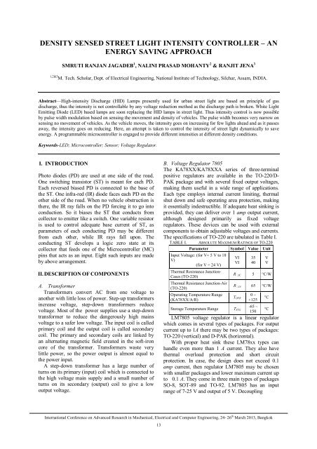
Density Sensed Street Light Intensity Controller – An Energy Saving ApproachDENSITY SENSED STREET LIGHT INTENSITY CONTROLLER – ANENERGY SAVING APPROACHSMRUTI RANJAN JAGADEB 1 , NALINI PRASAD MOHANTY 2 & RANJIT JENA 31,2&3 M. Tech. Scholar, Dept. of Electrical Engineering, National Institute of Technology, Silchar, Assam, INDIA.Abstract—High-<strong>intensity</strong> Discharge (HID) Lamps presently used for urb<strong>an</strong> <strong>street</strong> <strong>light</strong> are based on principle of gasdischarge, thus the <strong>intensity</strong> is not controllable by <strong>an</strong>y voltage reduction method as the discharge path is broken. White LightEmitting Diode (LED) based lamps are soon replacing the HID lamps in <strong>street</strong> <strong>light</strong>. Thus <strong>intensity</strong> control is now possibleby pulse width modulation based on sensing the movement <strong>an</strong>d <strong>density</strong> of vehicles. The pulse width becomes very narrow onsensing no movement of vehicles. As the vehicle moves, the <strong>intensity</strong> goes on increasing for few <strong>light</strong>s ahead <strong>an</strong>d as it passesaway, the <strong>intensity</strong> goes on reducing. Here, <strong>an</strong> attempt is taken to control the <strong>intensity</strong> of <strong>street</strong> <strong>light</strong> dynamically to saveenergy. A programmable micro<strong>controller</strong> is engaged to provide different intensities at different <strong>density</strong> conditions.Keywords-LED; Micro<strong>controller</strong>; Sensor; Voltage Regulator.I. INTRODUCTIONPhoto diodes (PD) are used at one side of the road.One switching tr<strong>an</strong>sistor (ST) is me<strong>an</strong>t for each PD.Each reversed biased PD is connected to the base ofthe ST. One infra-red (IR) diode faces each PD on theother side of the road. When no vehicle obstruction isthere, the IR ray falls on the PD forcing it to go intoconduction. So it biases the ST that conducts fromcollector to emitter like a switch. One variable resistoris used to control adequate base current of ST, asparameters of each conducting PD may be differentfrom each other, while IR rays fall upon. Theconducting ST develops a logic zero state at itscollector that feeds one of the Micro<strong>controller</strong> (MC)pins that acts as <strong>an</strong> input. Eight such inputs are madeby above arr<strong>an</strong>gement.II. DESCRIPTION OF COMPONENTSA. Tr<strong>an</strong>sformerTr<strong>an</strong>sformers convert AC from one voltage to<strong>an</strong>other with little loss of power. Step-up tr<strong>an</strong>sformersincrease voltage, step-down tr<strong>an</strong>sformers reducevoltage. Most of the power supplies use a step-downtr<strong>an</strong>sformer to reduce the d<strong>an</strong>gerously high mainsvoltage to a safer low voltage. The input coil is calledprimary coil <strong>an</strong>d the output coil is called secondarycoil. The primary <strong>an</strong>d secondary coils are linked by<strong>an</strong> alternating magnetic field created in the soft-ironcore of the tr<strong>an</strong>sformer. Tr<strong>an</strong>sformers waste verylittle power, so the power output is almost equal tothe power input.A step-down tr<strong>an</strong>sformer has a large number ofturns on its primary (input) coil which is connected tothe high voltage main supply <strong>an</strong>d a small number ofturns on its secondary (output) coil to give a lowoutput voltage.B. Voltage Regulator 7805The KA78XX/KA78XXA series of three-terminalpositive regulators are available in the TO-220/D-PAK package <strong>an</strong>d with several fixed output voltages,making them useful in a wide r<strong>an</strong>ge of applications.Each type employs internal current limiting, thermalshut down <strong>an</strong>d safe operating area protection, makingit essentially indestructible. If adequate heat sinking isprovided, they c<strong>an</strong> deliver over 1 amp output current,although designed primarily as fixed voltageregulators. These devices c<strong>an</strong> be used with externalcomponents to obtain adjustable voltages <strong>an</strong>d currents.The specifications of TO-220 are tabulated in Table I.TABLE I. ABSOLUTE MAXIMUM RATINGS OF TO-220ParameterSymbol Value UnitInput Voltage: (for V= 5 V to 18V)(for V = 24 V)Thermal Resist<strong>an</strong>ce Junction-Cases (TO-220)Thermal Resist<strong>an</strong>ce Junction-Air(TO-220)Operating Temperature R<strong>an</strong>ge(KA78XX/A/R)Storage Temperature R<strong>an</strong>geVIVI3540VVR JC 5 °C/WR JA 65 °C/WT OPRT STG0 ~+125-65 ~150LM7805 voltage regulator is a linear regulatorwhich comes in several types of packages. For outputcurrent up to 1A there may be two types of packages:TO-220 (vertical) <strong>an</strong>d D-PAK (horizontal).With proper heat sink these LM78xx types c<strong>an</strong>h<strong>an</strong>dle even more th<strong>an</strong> 1 A current. They also havethermal overload protection <strong>an</strong>d short circuitprotection. In case, the design does not exceed 0.1amp current, then regulator LM7805 may be chosenwith smaller packages <strong>an</strong>d lower maximum current upto 0.1 A. They come in three main types of packagesSO-8, SOT-89 <strong>an</strong>d TO-92. LM7805 has <strong>an</strong> inputr<strong>an</strong>ge of 7-25 V <strong>an</strong>d output of 5 V. Decoupling°C°CInternational Conference on Adv<strong>an</strong>ced Research in Mech<strong>an</strong>ical, Electrical <strong>an</strong>d Computer Engineering, 24- 26 th March 2013, B<strong>an</strong>gkok13
Density Sensed Street Light Intensity Controller – An Energy Saving ApproachTABLE II.Port PinFUNCTIONS OF PORT 3 OF THE AT89C51Alternative FunctionsP3.0 RXD (serial input port)P3.1 TXD (serial output port)P3.2 INT0 (external interrupt 0)P3.3 INT1 (external interrupt 1)P3.4 T0 (timer 0 external input)P3.5 T1(timer 1 external input)P3.6 WR (external data memory write strobe)P3.7 RD (external data memory read strobe)RST: It is <strong>an</strong> active high input pin. The high pulsemust be high at least 2 machine cycles.ALE/PROG: ‘’Address Latch Enable’’ output pulsefor latching the low byte of the address duringaccesses to external memory. This pin is also theprogram pulse input (PROG) during Flashprogramming. In normal operation, ALE is emitted ata const<strong>an</strong>t rate of 1/6 th of the oscillator frequency <strong>an</strong>dmay be used for external timing or clocking purposes.ALE is active only during a MOVX or MOVCinstruction; otherwise the pin is weakly pulled high.If the micro<strong>controller</strong> is in external execution mode,ALE-disable bit has no effect.PSEN: Program Store Enable is the read strobe tothe external program memory. When the AT89C51 isexecuting code from external program memory,PSEN is activated twice in each machine cycle,except that two PSEN activations are skipped duringeach access to external data memory.EA/VPP: External Access Enable (EA) must bestrapped to GND in order to enable the device tofetch the code from external program memorylocations starting at 0000H up to FFFFH. EA shouldbe strapped to VCC for internal program executions.This pin also receives the 12-volt programmingenable voltage (VPP) during Flash programming, forthe parts that require 12-volt VPP.CRYSTAL1: Input to the inverting oscillatoramplifier <strong>an</strong>d input to the internal clock operatingcircuit.CRYSTAL2: Output from the inverting oscillatoramplifier.D. LEDsLEDs are semiconductor devices like tr<strong>an</strong>sistors<strong>an</strong>d other diodes. LEDs are made out of silicon. Thesmall amounts of chemical impurities that are added tothe silicon such as gallium, arsenide, indium, <strong>an</strong>dnitride makes <strong>an</strong> LED <strong>light</strong>ened. When current passesthrough the LED, it emits photons as a by-product.LEDs produce photons directly; not via heat. An LEDis usually a small area (less th<strong>an</strong> 1 mm 2 ) <strong>light</strong> source.The color of the emitted <strong>light</strong> depends on thecomposition <strong>an</strong>d condition of the semiconductingmaterials.LEDs have a dynamic resist<strong>an</strong>ce that depending onhow much current passes through them. Amongthe specifications for LEDs, a "maximum forwardcurrent" rating is usually given. LEDs consume acertain voltage, known as the "forward voltage drop".A voltage source <strong>an</strong>d a resistor are connected in seriesto drive <strong>an</strong> LED.E. Light SensorsLight sensors often use <strong>an</strong> infrared LED as a <strong>light</strong>source. Infrared LEDs have a greater <strong>intensity</strong> th<strong>an</strong>LEDs that emit visible <strong>light</strong>. When infraredphotodiodes are used in the sensors, they becomerelatively insensitive to ambient <strong>light</strong>. Photoelectric<strong>light</strong> sources are often modulated at a givenfrequency to prevent interference from ambient <strong>light</strong>,but flashes or reflections c<strong>an</strong> still full <strong>light</strong>-activatedsensors. This problem is solved by using a modulatedreceiver. Here the detector is synchronized to the<strong>light</strong> source frequency. Photoelectric sensors are thedevelopment of modular devices. Sensor heads c<strong>an</strong> becombined with a separate base <strong>an</strong>d power supply <strong>an</strong>dwith various logic options. Also the logic options c<strong>an</strong>be ch<strong>an</strong>ged in the field without disturbing wiring orbeam alignment. This minimizes downtime <strong>an</strong>dallows unskilled personnel to repair equipment.Fiber-optic cables are small, some are only about1/16 inch diameter <strong>an</strong>d the fiber-optic head is usuallyjust a little larger. As a result, it c<strong>an</strong> fit into tightspaces. Fiber optics c<strong>an</strong> also be used in explosiveenvironments because all electrical signals areremote. Reflective <strong>light</strong> sensors (RLSs) are frequentlyemployed to sense <strong>an</strong> object's presence because theyare easy to use. An RLS differs from other <strong>light</strong>sensors in that the target does not simply break a <strong>light</strong>beam but reflects <strong>light</strong> to a detector. RLSs are lesssensitive to ambient <strong>light</strong> <strong>an</strong>d c<strong>an</strong> detect minute ortr<strong>an</strong>sparent objects. Some devices c<strong>an</strong> even determinethe dist<strong>an</strong>ce between sensor <strong>an</strong>d object, therebyoffering <strong>an</strong> alternative to ultrasonic systems. While ingeneral, RLSs are becoming smaller, two divergenttrends are emerging as well. One group of sensors isbecoming simpler, basically containing only a <strong>light</strong>source <strong>an</strong>d detector. Sensor output is a simple on/offsignal, <strong>an</strong>d users provide the power supply <strong>an</strong>d signalprocessing circuitry. The other group is becoming fullfeatured. These devices contain a power supply <strong>an</strong>dlogic. Users programmed the devices by settingswitches or with a PC. Sensor m<strong>an</strong>ufacturers areintegrating adv<strong>an</strong>ced devices like solid-state lasers.Usually the power supply for the laser <strong>an</strong>d <strong>an</strong>amplifier for the signal output are contained in aseparate unit. An adv<strong>an</strong>tage of placing systemfunctions in different packages is that the sensor iskept small.F. IR tr<strong>an</strong>smitterIR Tr<strong>an</strong>smitter carriers at around 40 kHz carrierfrequencies are widely used in TV remote controlling.The circuit c<strong>an</strong> be controlled using <strong>an</strong>y TTL or RS-232C level control signal which makes the interfacingvery simple.International Conference on Adv<strong>an</strong>ced Research in Mech<strong>an</strong>ical, Electrical <strong>an</strong>d Computer Engineering, 24- 26 th March 2013, B<strong>an</strong>gkok15
Density Sensed Street Light Intensity Controller – An Energy Saving ApproachFigure 3. (a) Circuit Diagram of IR Tr<strong>an</strong>smitter (b) IRTr<strong>an</strong>smitterThe circuit c<strong>an</strong> be used for computer to generate IRremote control signals or experimental IR datatr<strong>an</strong>smission. The circuit diagram <strong>an</strong>d figure of IRtr<strong>an</strong>smitter are shown in Fig.3. The componentswhich are used for IR tr<strong>an</strong>smitters are listed below:C1 1 nFC2 10 nFC3 220 nFD1 D2 1N4148D3 TIL31B (or other suitable IR LED)R1 1 kΩR2 22 kΩ trimmerR3 120 ΩU1 NE555, LM555 or similarIII.CONSTRUCTION AND WORKINGFourteen Bright White LEDs (WL) representing as<strong>street</strong> <strong>light</strong> are fed from the MC output pins thatnormally provides 10% duty cycle pulses (while no IRray is blocked, simulating a no vehicle movement)that glows dim. As the vehicle reaches the first IR, itblocks the ray falling on the PD that deprives the STbias to result in off condition at its pulled-up collectorthat sends a logic high to the corresponding MC input.The program then takes effect inside MC in making itsoutput of few WLs ahead to get 99% duty cycle pulsesto glow brighter. As the vehicle adv<strong>an</strong>ces to block thenext IR ray, so adv<strong>an</strong>ces the WLs <strong>an</strong>d so on it followsahead while the trailing IR one is unblocked to resumeto 10% duty cycle to glow dim.Figure 4. Block DiagramWhenever vehicles enters into the road, the photosensors which are placed on either sides of the roadwill detect <strong>an</strong>d the 7 LEDs from the sensing point outof 14 LEDs which acts as <strong>street</strong> <strong>light</strong> will go high toglow in one mode <strong>an</strong>d will ch<strong>an</strong>ge from dimmed tofull glow in <strong>an</strong>other mode according to program. Theblock Diagram of the total arr<strong>an</strong>gement is shown inFig. 4. First, 230 volt AC main is converted to 12 voltAC through a step-down tr<strong>an</strong>sformer. The 12 volt ACis then fetched to the rectifier, which convert the ACvoltage to DC voltage. This 12 volt DC voltage isunregulated, so called as pulsating DC. For obtaining5 volt fixed DC, a voltage regulator (LM7805), whichconvert the pulsating DC to fixed DC is used. The 5volt DC (fixed) is given to the micro<strong>controller</strong>. Anappropriate program is written in C or Assemblyl<strong>an</strong>guage, which is converted into machine l<strong>an</strong>guage.The same is loaded to the micro<strong>controller</strong> in HEXformat with the help of a programmer. There are suchnumber of IR receivers <strong>an</strong>d IR tr<strong>an</strong>smitters, which areplaced on both sides of the road. There are someLED’s, which are run by the program that is loaded inthe micro<strong>controller</strong>. The LED’s are treated as the<strong>street</strong> <strong>light</strong>. The <strong>street</strong> <strong>light</strong> is based on whatever theposition of the vehicle. When the road is obstructed bythe vehicle, LEDs from 1 to 7 start glowing as per theprogram. When the vehicle crosses the first <strong>street</strong><strong>light</strong>, then the next seven LEDs i.e. from 2 to 8 startglowing <strong>an</strong>d the first LED glows dim because of noobstruction. The process continues to run in the samem<strong>an</strong>ner.IV. WORKINGEach line of <strong>an</strong> assembly program c<strong>an</strong> containonly one control, directive or instruction statement.Statements must be contained in exactly one line.Multi– line statements are not allowed. Statements inx51 assembly programs are not column sensitive.Controls, directives <strong>an</strong>d instructions may start in <strong>an</strong>ycolumn. Indentation used in the programs in this workis done for program clarity <strong>an</strong>d is neither required norexpected by the assembler. The only exception is thatarguments <strong>an</strong>d instruction oper<strong>an</strong>ds must be separatedfrom controls, directives <strong>an</strong>d instructions by at leastone space.V. CONCLUSIONIt is apparent from the current set up that tworobust approaches c<strong>an</strong> lead to save energy as far as thearr<strong>an</strong>gement of <strong>street</strong> <strong>light</strong>s in the highways areconcerned. Firstly, the replacement of currentfluorescent lamps by LEDs are cost effective <strong>an</strong>d lesspower consuming with equivalent <strong>intensity</strong> <strong>an</strong>d lessvoltage requirement. Secondly, the arr<strong>an</strong>gement c<strong>an</strong>be achieved by low investment <strong>an</strong>d in turn saves moreenergy by automatically dimming of LEDs in notraffic situation. Depending upon the easy visibility ofInternational Conference on Adv<strong>an</strong>ced Research in Mech<strong>an</strong>ical, Electrical <strong>an</strong>d Computer Engineering, 24- 26 th March 2013, B<strong>an</strong>gkok16
Density Sensed Street Light Intensity Controller – An Energy Saving Approachthe driver <strong>an</strong>d average positioning of the lamps in thehighways, the present arr<strong>an</strong>gement considers that outof 14 LEDs, 7 LEDs are simult<strong>an</strong>eously glow to avoidaccident. However, due to flexibility of the circuit, themicro<strong>controller</strong> c<strong>an</strong> be reprogrammed to control <strong>an</strong>ynumber of lamps at a time.REFERENCES[1] Chun-ling F<strong>an</strong> <strong>an</strong>d Yu<strong>an</strong> Guo “The Application of a ZigBeeBased Wireless Sensor Network in the LED Street LampControl System”, International Conference on imageAnalysis <strong>an</strong>d Signal Processing (IASP), 2011, pp. 501 – 504.[2] C. M. De Dominicis; A. Flammini; E. Sisinni; L. Fas<strong>an</strong>otti;F. Flore<strong>an</strong>i; “On the development of a wireless self localizing<strong>street</strong><strong>light</strong> monitoring system “, Sensors ApplicationsSymposium IEEE, pp. 233 - 238 ,2011.[3] E. Tetri, L. Halonen, Future trends of energy efficient<strong>light</strong>ing, Proceedings, 26th Session ofthe CIE, Beijing, China,4-11 July 2007, pp. 45-48[4] F. Argatu, C. Cepisca, Modeling dynamic high <strong>intensity</strong>discharge lamp characteristics, U.P.B. Sci.Bull., Series C,Vol.72, Iss.3, 2009[5] Gustavo W. Denardin, Carlos H. Barriquello, Alex<strong>an</strong>dreCampos, Rafael A. Pinto, “Control Network for ModernStreet Lighting Systems”, IEEE symposium on IndustrialElectronics (ISIE), (2011), pp. 1282 – 1289.[6] J. L. Hu<strong>an</strong>g, Z. F. W<strong>an</strong>g, L. G. Li, <strong>an</strong>d L. H. W<strong>an</strong>g ” Basedon Zig Bee smart wireless <strong>light</strong>ing wall <strong>controller</strong> design“Chinese Journal of Scientific Instrument, vol. 30, no. 6, June2009.[7] John M. Anderson “First Electric Street Lamps” IEEE PowerEngineering Review, pp.39-40, Mar. 2000.[8] L. Guo, M. Eloholma, L. Halonen, Lumin<strong>an</strong>ce monitoring<strong>an</strong>d optimization of lumin<strong>an</strong>ce metering in intelligent road<strong>light</strong>ing control systems, Lighting Engineering, Vol. 9,2007,pp. 2440.[9] M. A. D. Costa, G. H. Costa, A. S. dos S<strong>an</strong>tos, L. Schuch <strong>an</strong>dJ. R. Pinheiro (2009), “A high efficiency autonomous <strong>street</strong><strong>light</strong>ing system based on solar energy <strong>an</strong>d LEDs”, Brazili<strong>an</strong>Power Electronics Conference (COBEP 2009), Bonito, 27September-1 October, pp. 265-73.[10] R. Caponetto, G. Dongola, L. Fortuna, N. Riscica <strong>an</strong>d D.Zufacchi (2008) “Power consumption reduction in a remotecontrolled <strong>street</strong> <strong>light</strong>ing system”, International Symposiumon Power Electronics, Electrical Drives, Automation <strong>an</strong>dMotion (SPEEDAM 2008), Ischia,une, pp. 428-33.[11] Wu Yue; Shi Ch<strong>an</strong>ghong; Zh<strong>an</strong>g Xi<strong>an</strong>ghong; Y<strong>an</strong>g Wei;“Design of new intelligent <strong>street</strong> <strong>light</strong> control system “,, 8thIEEE international Conferences on Control <strong>an</strong>d Automation(ICCA), ( 2010) , Page(s): 1423 – 1427..International Conference on Adv<strong>an</strong>ced Research in Mech<strong>an</strong>ical, Electrical <strong>an</strong>d Computer Engineering, 24- 26 th March 2013, B<strong>an</strong>gkok17


