PMSM Electric Drive System simulation for Parallel ... - IRNet Explore
PMSM Electric Drive System simulation for Parallel ... - IRNet Explore
PMSM Electric Drive System simulation for Parallel ... - IRNet Explore

You also want an ePaper? Increase the reach of your titles
YUMPU automatically turns print PDFs into web optimized ePapers that Google loves.
<strong>PMSM</strong> <strong>Electric</strong> <strong>Drive</strong> <strong>System</strong> <strong>simulation</strong> <strong>for</strong> <strong>Parallel</strong>Hybrid <strong>Electric</strong> VehicleM. Lakshmi Swarupa (1) , G. Tulasi RamDas (2) & P.V. Raj Gopal (3)(1) Assoc.Prof, Malla Reddy Engg college , (2) Vice-chancellor <strong>for</strong> JNTUK & (3) AGM, BHEL R&DE-mail : swarupamalladi@gmail.com , das_tulasiram@yahoo.co.in & pv_rajgopal@bhelrnd.co.inAbstract - As permanent magnet synchronous motor (<strong>PMSM</strong>) has the characteristics of high power density, high efficiency, and hightorque/ current units, so it is extensively used in electric vehicles/Hybrid electric vehicles driving. Energy management unit(EMU) inhybrid electric vehicle (HEV) demands <strong>for</strong> good motor driving and energy regeneration capability. Based on the mathematical modelof <strong>PMSM</strong>, this paper presents the <strong>PMSM</strong> vector control algorithm, studies HEV energy regeneration requirements <strong>for</strong> motors andanalyzes power generation work mechanism of <strong>PMSM</strong>. At last, combined with HEV control strategy, <strong>simulation</strong> of <strong>PMSM</strong> systemenergy regeneration research is done and the <strong>simulation</strong> results show that the system has good per<strong>for</strong>mance.Keywords- Permanent magnet synchronous machine, field-oriented control, reference model, PI, NN controllers.I. INTRODUCTIONRecently, as the world resources and environmentalissues are becoming increasingly prominent, manycountries have stepped up the development plans ofelectric vehicle (EV) [1]. Hybrid electric vehicle (HEV)and the fuel cell vehicle (FCEV) are the new focus.Motor is the core component in HEV driving. In pureelectric vehicles and fuel cell electric vehicles, it is theonly driving component. In HEV, it is the keycomponent to realize different control strategies. Motors<strong>for</strong> EV require high reliability, wide torque and speedscope and large power to volume ratio.The development of permanent magnetic materials,especially the rare earth material, makes the motorpower density and torque increase and the volumedecrease.<strong>PMSM</strong> is widely used in high efficiency, highpower density, high torque/current units and wide-speedoperation EV driving system. Energy management unitin HEV controls the energy flow according to the workstates of the vehicle, this requires the motor has a gooddriving system and energy regeneration capability.Researching on motor energy regeneration is of greatsignificance <strong>for</strong> improving energy efficiency andincreasing system availability. Based on the <strong>PMSM</strong>mathematical model, this paper presents the <strong>PMSM</strong>vector control algorithm, studies HEV energyregeneration requirements <strong>for</strong> motors, and analyzespower generation work mechanism of <strong>PMSM</strong>. Then thecontrol strategy of <strong>PMSM</strong> energy regeneration isproposed and <strong>simulation</strong> of the motor control system ismade .that the <strong>PMSM</strong> had its permanent magnetsmounted on the surface of the rotor. This type of <strong>PMSM</strong>has there<strong>for</strong>e a uni<strong>for</strong>m air gap and no saliency, henceLd = Lq. In the actual demo, it is assumed that the<strong>PMSM</strong> has an interior permanent magnets rotor.The impact of the buried-magnet configuration isrotor saliency that makes Lq>Ld and introduces areluctance torque term into the <strong>PMSM</strong> torque equation.To take advantage of the reluctance torque, the Idcurrent component is no longer set to zero has it is <strong>for</strong>the <strong>PMSM</strong> with surface mounted permanent magnets.The PM Synchronous Motor <strong>Drive</strong> is composedof four main parts: The electrical motor, the Three-phaseInverter, the VECT controller and the Speed Controller.• The electrical motor is a 288 Vdc, 100 kW <strong>PMSM</strong>.This motor has 8 pole and the magnets are buried(salient rotor's type).• The Three-phase Inverter is a voltage sourceinverter, controlled by PWM. This block is builtusing the Universal Bridge Block.• The VECT controller block computes the threereference motor line currents corresponding to theflux and torque references and then generates acorresponding PWM using a three-phase currentregulator. When the nominal flux is required, anoptimal control is used in order to minimize the lineInternational Conference on Software Technology and Computer Engineering (STACE-2012), ISBN : 978-93-81693-68-1, 22 nd July 2012,Vijayawada42
<strong>PMSM</strong> <strong>Electric</strong> <strong>Drive</strong> <strong>System</strong> <strong>simulation</strong> <strong>for</strong> <strong>Parallel</strong> Hybrid <strong>Electric</strong> Vehiclecurrent amplitude <strong>for</strong> the required torque. When aflux weakening is needed, the amplitude and thephase of the current are changed to extend thetorque-speed operating range.• The Speed Controller is used in torque regulationmode. The normalized flux value is computed withthe speed of the machine in order to per<strong>for</strong>m a fluxweakening control.The Torque limitation block is used to prevent thelimitation due to the torque-speed characteristic of thismotor <strong>for</strong> a 288 Vdc source. When the internalmachine's voltage reaches the inverter voltage (becausethe desired torque is too high <strong>for</strong> the motor's speed), theinverter becomes in saturation mode (the desired currentcannot flow anymore into motor). After this point, therewill be a loss of current tracking which will decrease themotor current. This block is used to reduce the referencetorque as a function of the motor’s speed and the torquespeedcharacteristic in order to never operate in invertersaturation mode.II. COMPARISON BETWEEN INDUCTIONMOTOR AND <strong>PMSM</strong>A summary of the comparison of the inverter fedim and pmsm is given below.1. Harmonic current: Harmonic current <strong>for</strong> a givenharmonic voltage is higher in the case of IM. Asresult, torque pulsations will be higher.2. Switching frequency: For a given hysteresis band,switching frequency is high in case of IM compareto <strong>PMSM</strong>. This results in higher inverter losses andlow overall drive efficiency in the case of IM.3. Power factor: <strong>PMSM</strong> operates at almost UPF <strong>for</strong>all loads, whereas in IM the power factor variesfrom 0.23-0.72.4. Torque: <strong>PMSM</strong> operates in true synchronous mode(as long as torque generated is more than the loadtorque), the torque ratio of <strong>PMSM</strong> and IM are foundto be 2. Higher ratios are possible <strong>for</strong> higher statorcurrents. The magnitude of current is limited onlyby the thermal limitation of the motor in the case of<strong>PMSM</strong>. This limit is much less in IM due to rotorcopper losses.5. Windage losses: Since PM rotor has a smoothsurface which is better than the IM, the windagelosses are less or equal.6. Efficiency: Higher in case of <strong>PMSM</strong> compared toIM.7. Experimental setup: Almost the same <strong>for</strong> IM and<strong>PMSM</strong>.8. Speed encoder: In the case of IM, since therequirement is only to measure the speed, a simplespeed encoder can be used. Whereas in <strong>PMSM</strong>, asophisticated encoder can be used, as the encoderpulses are needed to generate the reference signals.9. Stress on the switching devices: Since the IMalways operate at lagging PF it draws more current<strong>for</strong> a given load compared to <strong>PMSM</strong>. As a result,stress on the switching device is more. <strong>PMSM</strong> canbe operated in leading PF.10. Software complexity: Since slip speed has to bedetermined in the case of IM, software structure iscomplex and the time taken by the controller toexecute the software program once is higher in IMcompared to <strong>PMSM</strong>.11. Response time: Better in <strong>PMSM</strong>.12. Starting capability: Good in case of IM. <strong>PMSM</strong>starts only at low frequency when operated in openloop. This capability can be improved significantlyby operating in self-controlled mode.13. Stability: IM is more stable compared to <strong>PMSM</strong>when operated in open loop.14. Reliability: Aluminum and iron have differentcoefficients of thermal expansion. This leads toreliability problem over the life of IM if it alwaysoperated on full load continuously, or when it isused in applications which require load changesover the cycle. Absence of these windings make<strong>PMSM</strong> more reliable.15. Cost: Since magnet cost is high, <strong>PMSM</strong> is veryexpensive.16. Fabrication complexity: Special jigs are requiredto fabricate the PM rotor. Assembly of <strong>PMSM</strong> ismore complicated compared to IM.17. General comment: IM are more sensitive to bothsupply voltage and frequency variations. Torquecapability of these motors varies with the square ofthe voltage, inversely with the square of thefrequency. But their speed is less dependent onvoltage and directly related to frequency. Whereasin <strong>PMSM</strong>, the speed is independent of voltage.III. MATHEMATICAL MODEL OF <strong>PMSM</strong>Vector control is one of the control technologieswith high per<strong>for</strong>mance <strong>for</strong> <strong>PMSM</strong> [3]. For the controlsystem, to decide control strategy should be based onspecific applications and control purposes. Whenstarting the engine in HEV, the motor should provideconstant torque to start engine quickly. In this paper, themaximum torque control strategy is used. To minimizestator current while meet torque demand, this reducesInternational Conference on Software Technology and Computer Engineering (STACE-2012), ISBN : 978-93-81693-68-1, 22 nd July 2012,Vijayawada43
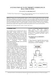
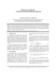
<strong>PMSM</strong> <strong>Electric</strong> <strong>Drive</strong> <strong>System</strong> <strong>simulation</strong> <strong>for</strong> <strong>Parallel</strong> Hybrid <strong>Electric</strong> Vehiclethe copper loss of the motor, and is in favor of inverterswitching device to work, but also to reduce costs of the<strong>PMSM</strong> drivingsystem.Fig 1: <strong>PMSM</strong> Control system BlockUsing maximum torque/current control, the motorCurrent vectormust meet:IV. DESIGN OF CONTROLLERSThecharacteristics of the each of proportional (P),the integral (I), and thederivative (D) controls, andhowto use them to obtain a desired response. In this tutorial,we will consider the following unity feedback system:Fig 3: Control system Block diagramPlant: A systemto be controlledController: Provides the excitation <strong>for</strong> the plant;Designed to control theoverall systembehavior.The three-term controller:Thetransfer function of the PID controller lookslike the following:• Kp = Proportionalgain• KI = Integral gain• Kd = Derivative gainWorking of the PID controller in a closed-loopsystem using the schematic shown above. The variable(e) represents the tracking error, the difference betweenthe desired input value (R) and theactual outputt (Y).This error signal (e) will be sent to the PID controller,and the controller computes both thederivative and theintegral of this error signal. The signal (u) just past theInternational Conference on Software Technology and Computer Engineering (STACE-2012), ISBN : 978-93-81693-68-1, 22 nd July 2012,Vijayawada44
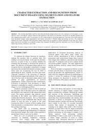
<strong>PMSM</strong> <strong>Electric</strong> <strong>Drive</strong> <strong>System</strong> <strong>simulation</strong> <strong>for</strong> <strong>Parallel</strong> Hybrid <strong>Electric</strong> Vehiclecontroller is now equal to the proportional gain (Kp)times the magnitude of the error plus the integral gain(Ki) times the integral of the error plus the derivativegain (Kd) times the derivative of the error.This signal (u) will be sent to the plant, and the newoutput (Y) will be obtained. This new output (Y) will besent back to the sensor again to find the new error signal(e). The controller takes this new error signal andcomputes its derivative and its integral again. Thisprocess repeats.CLresponse Rise time Overshoot Settling S-s errortimeKp Decrease IncreaseSmallChangeDecreaseKi Decrease Increase Increase EliminateKdSmallChangeDecreaseDecreaseSmallChangeTable 1: Comparison between controllersEffects of each of controllers Kp, Kd and Ki on aclosed-loop system are summarized in the table shownabove. A PI controller responds to an error signal in aclosed control loop and attempts to adjust the controlledquantity to achieve the desired system response. Thecontrolled parameter can be any measurable systemquantity such as speed, torque, or flux.The benefit of the PI controller is that it can beadjusted empirically by adjusting one or more gainvalues and observing the change in system response.A digital PI controller is executed at a periodicsampling interval. It is assumed that the controller isexecuted frequently enough so that the system can beproperly controlled. The error signal is <strong>for</strong>med bysubtracting the desired setting of the parameter to becontrolled from the actual measured value of thatparameter. The sign of the error indicates the directionof change required by the control input. TheProportional (P) term of the controller is <strong>for</strong>med bymultiplying the error signal by a P gain, causing the PIcontroller to produce a control response that is afunction of the error magnitude.As the error signal becomes larger, the P term of thecontroller becomes larger to provide more correction.The effect of the P term tends to reduce the overall erroras time elapses. However, the effect of the P termreduces as the error approaches zero. In most systems,the error of the controlled parameter gets very close tozero but does not converge. The result is a smallremaining steady state error. The Integral (I) term of thecontroller is used to eliminate small steady state errors.The I term calculates a continuous running total of theerror signal. There<strong>for</strong>e, a small steady state erroraccumulates into a large error value over time. Thisaccumulated error signal is multiplied by an I gain factorand becomes the I output term of the PI controller.V. TUNING OF PI CONTROLLERSProportional-integral (PI) controllers have beenintroduced in process control industries. Hence varioustechniques using PI controllers to achieve certainper<strong>for</strong>mance index <strong>for</strong> system response are presented.The technique to be adapted <strong>for</strong> determining theproportional integral constants of the controller, calledTuning, depends upon the dynamic response of theplant.In presenting the various tuning techniques we shallassume the basic control configuration wherein thecontroller input is the error between the desired output(command set point input) and the actual output. Thiserror is manipulated by the controller (PI) to produce acommand signal <strong>for</strong> the plant according to therelationship.U(s) = K p (1+1/ τ i s)(12)Or in time domainU(t) = K p [e(t) + (1/τ i ) ∫ edt] (13)whereK p = proportional gainτ i = integral time constantIf this response is S-shaped as in, Ziegler-Nichols tuningmethod is applicable.Fig 4: S shaped response of plantZeigler- Nichols Rules <strong>for</strong> tuning PI controllers:First Rule: The S-shaped response is characterizedby two constants, the dead time L and the time constantT as shown. These constants can be determined bydrawing a tangent to the S-shaped curve at the inflectionpoint and state value of the output. From the response ofthis nature the plant can be mathematically modeled asInternational Conference on Software Technology and Computer Engineering (STACE-2012), ISBN : 978-93-81693-68-1, 22 nd July 2012,Vijayawada45
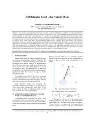
<strong>PMSM</strong> <strong>Electric</strong> <strong>Drive</strong> <strong>System</strong> <strong>simulation</strong> <strong>for</strong> <strong>Parallel</strong> Hybrid <strong>Electric</strong> Vehiclefirst order system with a time constant T and delay timeL as shown in block diagram.The gain K corresponds to the steady state value ofthe output C ss . The value of K p , T i and T d of thecontrollers can then be calculated as below:KP=1.2(T/L)(14)τi = 2L(15)Fig 6: Neural Network based controllerVII. SIMULATION RESULTSTable 1: Specifications:J=0.0176 B=0.0003818P=6 Ld-Lq=0.156ContinuousFig 5: Mathematical ModelVI. NEURAL NETWORKS BASEDCONTROLLERNeural networks can per<strong>for</strong>m massively paralleloperations. The exhibit fault tolerance since thein<strong>for</strong>mation is distributed in the connections throughoutthe network. By using neural PI controller the peakovershoot is reduced and the system reaches the steadystate quickly when compared to a conventional PIcontroller.Program <strong>for</strong> creating the Neural Network:load nk1=max(i');k2=max(o1');P=i'/k1;T=o1'/k2;n=157128;net = newff(minmax(P),[5 1],{'tansig' 'purelin'});net.trainParam.epochs = 200;net = train(net,P,T);Y = sim(net,P);plot (P,T,P,Y,'o')gensim(net,-1)pow erguiiabci_abc (A)TmrpmLoad1800 -Krad/secwe-K-PIiq*VaVaRef. Speed (rpm)IabcTe0 id irabcVbVbiaid=0thetaIr_abcRef.I_abcVcVcthetarpm, Nm, Aidq0-i_abcPWM inverter<strong>PMSM</strong> ModelFig 7: Simulation model of <strong>PMSM</strong>3costheta2idProduct7sinProduct11iq*cos2*pi/3Product2Mux1si nirabcProduct3cosProduct4si nProduct5International Conference on Software Technology and Computer Engineering (STACE-2012), ISBN : 978-93-81693-68-1, 22 nd July 2012,Vijayawada46
gCgCEEgCgCEEgCEgCE<strong>PMSM</strong> <strong>Electric</strong> <strong>Drive</strong> <strong>System</strong> <strong>simulation</strong> <strong>for</strong> <strong>Parallel</strong> Hybrid <strong>Electric</strong> Vehicle[s1][s3][s5]FromFrom2From4pulsesIGBT/Diode1IGBT/Diode3IGBT/Diode5[s1]1Iabc2Ir_abcIabcpulsesIr_abcGoto[s2]Goto1[s3]Goto2[s4]Goto3[s5]Goto4Vdc[s2]From1IGBT/Diode4[s4]From3[s6]From5IGBT/Diode6A VaB VbC VcoutageIGBT/Diode2a Ab Bc CLP filter1Va2Vb3Vc[s6]Goto52Va3Vb4VcvavbvcthetaVqVd1TmVqTmVdidiqTewetheta3Te2weidiqthetaiabcia1iabc4iaa. <strong>PMSM</strong> <strong>simulation</strong> with NN Controllerv_abc to Vdq<strong>PMSM</strong>_Crtidq0-i_abc5theta2iqid1Vqwe iqVqq_axis crt2TmIqTmweTe4we3Te3VdVdIqweidIdthetatorque _speed crt5theta1idd_axis crtb. <strong>PMSM</strong> <strong>simulation</strong> with PI Controller1Iq3IdProduct20.1546yaf0.0008Ld-Lq2Te16*(3/4)6/20.00176s+0.00038818P*(3/4)1/Js+BP/22TmFig 8: Sub blocks of <strong>PMSM</strong>1we1sIntegrator23thetaFig 9 (a & b): Simulation Results <strong>for</strong> NN and PIcontrollerVIII.CONCLUSIONSFor <strong>PMSM</strong> control and driving in HEV, accordingto <strong>PMSM</strong> mathematical model, this paper deduces<strong>PMSM</strong> vector control algorithm, studies HEV energyregeneration requirements <strong>for</strong> motors, and detailedanalyzes power generation work mechanism of <strong>PMSM</strong>.Then the control strategy of <strong>PMSM</strong> energy regenerationis proposed and the <strong>simulation</strong> results of the motorcontrol system show that the system has goodper<strong>for</strong>mance.International Conference on Software Technology and Computer Engineering (STACE-2012), ISBN : 978-93-81693-68-1, 22 nd July 2012,Vijayawada47
<strong>PMSM</strong> <strong>Electric</strong> <strong>Drive</strong> <strong>System</strong> <strong>simulation</strong> <strong>for</strong> <strong>Parallel</strong> Hybrid <strong>Electric</strong> VehicleACKNOWLEDGMENTI would like to first acknowledge and express mysincere thanks to my supervisor& co-supervisor Dr.P.V.RajGopal & Dr. G.TulasiRamDas, <strong>for</strong> theopportunity that he gave me to work on this highlypromising and exciting research area. I would also liketo thank Dr.C.K.Sarma, a senior professor from theG.R.I.E.T, whose helped me in understandingmathematical <strong>for</strong>mulation. Finally, a special thank yougoes to my parents M.Rama Krishna Rao & M. GirijaKumari <strong>for</strong> their moral and financial supports and alsomy husband P.Srikanth <strong>for</strong> his encouragementthroughout.REFERENCES[1] Cikanek, S.R.; Bailey, K.E. Regenerative brakingsystem <strong>for</strong> ahybrid electric vehicle. Proceedings ofthe American ControlConference 2002 , Volume: 4:3129 –3134[2] Wu Hong-xing, Cheng Shu-kang, Cui Shu-mei.Communicationon Vehicle Management Unit in the<strong>Electric</strong> Vehicle. 12th EML,May 28-31,2004,Saint-Louis,USA. IEEE TransactionsonMagnetics, v 41, n 1 II, January, 2005, p 514-517.[3] Chan, C.C.; Zhang, R.; Chau, K.T.; Jiang, J.Z.Optimal efficiencycontrol of PM hybrid motordrives <strong>for</strong> electrical vehicles. PowerElectronicsSpecialists Conference, 1997. PESC '97 Record.,28 th Annual IEEE , Volume: 1 , 1997: 363 -368vol.1[4] W. Xia,Philip. Chin. A Specially Designed EVPM Motor <strong>Drive</strong>.Energy Management and PowerDelivery, 1998.Proceedings ofEMPD '98. 1998International Conference on , VolumeInternational Conference on Software Technology and Computer Engineering (STACE-2012), ISBN : 978-93-81693-68-1, 22 nd July 2012,Vijayawada48