Finite Element Analysis of Helical Coil Compression ... - IRNet Explore
Finite Element Analysis of Helical Coil Compression ... - IRNet Explore
Finite Element Analysis of Helical Coil Compression ... - IRNet Explore

Create successful ePaper yourself
Turn your PDF publications into a flip-book with our unique Google optimized e-Paper software.
ISBN: 978-93-81693-89-6<strong>Finite</strong> <strong>Element</strong> <strong>Analysis</strong> <strong>of</strong> <strong>Helical</strong> <strong>Coil</strong> <strong>Compression</strong>Spring for Three Wheeler Automotive Front SuspensionTausif M. Mulla 1 , Sunil J. Kadam 2 , Vaibhav S. Kengar 31 M.E. Design, Mech. Engg, Rajarambapu Institute <strong>of</strong> Technology, Islampur, Dist-Sangli; 2 M.E. CAD/CAM, Mech. Engg, Bharati Vidyapeeth’s College <strong>of</strong> Engineering, Kolhapur;3 Mech. Engg, Bharati Vidyapeeth’s College <strong>of</strong> Engineering, Kolhapur (Maharashtra, India).tausifultimate@yahoo.co.in, s.kad@rediffmail.com, vaibhavkengar@gmail.comAbstract: The current paper deals with the stress analysis <strong>of</strong> a helical coil compression spring, which is employed in threewheeler’s auto-rickshaw belonging to the medium segment <strong>of</strong> the Indian automotive market. In the design <strong>of</strong> this kind <strong>of</strong>spring both the elastic characteristics and the fatigue strength have to be considered as significant aspects. In addition to thisparticular elastic property, as a consequence <strong>of</strong> the research effort in reducing the mass <strong>of</strong> components typical <strong>of</strong> theautomotive industry, these springs have to face very high working stresses. The structural reliability <strong>of</strong> the spring musttherefore be ensured. So for this purpose the static stress analysis using finite element method has been done in order to findout the detailed stress distribution <strong>of</strong> the spring.Keywords- <strong>Helical</strong> <strong>Coil</strong> <strong>Compression</strong> Spring, <strong>Finite</strong> <strong>Element</strong> <strong>Analysis</strong>, Fatigue Strength1. INTRODUCTIONThree-Wheeled Vehicles (TWVs) form an essential part<strong>of</strong> public transport for the urban middle class population<strong>of</strong> India. Apart from India, TWVs are also being usedworld over for public transport and for carrying freight.The suspension system for such three wheeler’s vehiclesis very poor as concerned with the ride comfort <strong>of</strong> thepassengers. Relatively higher centre <strong>of</strong> gravity, the lack<strong>of</strong> differential for the driving rear axle have been cited ascontributors to rollovers and pitching. This also adds thediscomfort to passengers. Very few publications evaluatethe performance <strong>of</strong> TWVs in everyday use for masstransportation. Nowadays the trend in the industries ismoving towards the weight reduction in everycomponent and springs are also not exempted. Over thecountry side roads where these TWVs are widely usedfor carrying freight, the stress levels in the springs gohigh. As helical coil compression springs are one <strong>of</strong> themain parts <strong>of</strong> the suspension system, it becomes quitenecessary to do the complete stress analysis <strong>of</strong> the spring.As these springs undergo the fluctuating loading over theservice life, it becomes essential to find out the fatiguelimit <strong>of</strong> the same.Mechanical spring is defined as an elastic body thathas the primary function to deflect or distort under load,and to return to its original shape when the load isremoved. First step in the design <strong>of</strong> spring in general, isto determine the loads and the deflections required for agiven spring application depending upon the type <strong>of</strong> theloading. In addition to this tentative selection <strong>of</strong> thematerial must be made. In case <strong>of</strong> the most generalapproach for the spring design, the maximum stress inthe spring wire may be computed by superposition <strong>of</strong>direct shear and the torsional shear stress. To design thehelical coil compression spring for small pitch angle, avery common approach called as approximate theoryconsidering direct shear and effect <strong>of</strong> curvature isreferenced here.[1] The assumption is that an element <strong>of</strong>an axially loaded helical spring behaves as a straight barin pure torsion. If P be the load acting axially on thespring, d is the diameter <strong>of</strong> the spring wire, D is the meandiameter <strong>of</strong> the coil, and then forces acting on theelement are resolved into a twisting moment /2,acting in a radial plane and a direct axial shearing forceP. The stresses set up by the twisting moment areconsidered first and then superimposed on the stressesdue to the direct shear. But the maximum shear stressInternational Conference on Mechanical and Industrial Engineering129
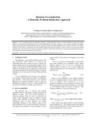
<strong>Finite</strong> <strong>Element</strong> <strong>Analysis</strong> <strong>of</strong> <strong>Helical</strong> <strong>Coil</strong> <strong>Compression</strong> Spring for Three Wheeler Automotive Front Suspensionoccurs at the inner side<strong>of</strong> the coil and may beconsiderablyhigher than the stress givenby elementarytheory by anamount depending on the spring index. Thereason for this is the shortfiber length at the innerside <strong>of</strong> the coil as shown inthe figure 1. Thus if the radialsections and rotatethrough an angle with respectto each otherabout springaxis, the inner fiberwillbe subjectedto much higher stress andshearing strainthan outside fiber . Also at the innerside <strong>of</strong> the coil,the shear stress due to the direct axial load P added suchthat it produce the torquemoment , at this point.Thus the stress range at inner side <strong>of</strong> the coil is normallymuch higherthan elsewhere and for this reason fatiguefailure generally starts at this region. Thereforemaximum shear stress at the inside <strong>of</strong> thecoil given byEq.1accurate results. However, with a higher number <strong>of</strong>elements and nonlinearity due to the contact between acoil spring and its seats, or between the coil and itself,each analysis could take hours to run. While the accuracy<strong>of</strong> the result is important, the computational time must bereasonable to incorporate FEA into coil spring design. Toresolvee lengthy computational timein a solid model, a 3-D beamelement is <strong>of</strong>ten selected to model a coil springand seats. Since the deformation <strong>of</strong> a seat undercompression is veryminimal andcan be ignored, thematerial properties <strong>of</strong> seats are setvery high to act as arigid body. Contact between a coiland seat, or betweenthe coil and itself, isdetected by gap elements or rigidelements.Eq. 1whereEq.2Eq. 2K is called as Wahl’s factor used for considering stresscorrection because <strong>of</strong> curvature effect and C is called asspring index. Form this it is clear that spring index hasstraight impact on the stress distribution.Stress obtainedby these formulae can be cross checked by finite elementmethod for better understanding <strong>of</strong> the stress distribution.The deflection is given by formulaEq.3Eq. 3where G is the shear modulus <strong>of</strong> material and N is thenumber <strong>of</strong> active coils in the spring.[1]2. FINITEELEMENT ANALYSISA primary reason to use FEA in coil spring design is theability to reduce error caused by the simplification <strong>of</strong>equations, mainly concerning the pitch angle. An FEA-based designbegins with the selection <strong>of</strong> the elementtype, how the model shouldbe constructed, how accuratethe results should be, and how fast the model should run.The most accurate FEA results can be obtained bycreating 3-Dparts <strong>of</strong> a coilspring and itsseats, followedby meshing the parts with a 3-D solidelement. Finermeshing with higher-orderr elements will produce moreFigure1- <strong>Element</strong>al Section <strong>of</strong> <strong>Helical</strong> <strong>Coil</strong> <strong>Compression</strong>Spring [1]International Conference onMechanical and Industrial Engineering130
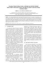
<strong>Finite</strong> <strong>Element</strong> <strong>Analysis</strong> <strong>of</strong> <strong>Helical</strong> <strong>Coil</strong> <strong>Compression</strong> Spring for Three Wheeler Automotive Front SuspensionGeometry and Material PropertiesDetailed specifications <strong>of</strong> the spring under considerationare given in the table 1. This spring is used in the TWV’sfront suspension. Spring is made up <strong>of</strong> ASTM A227material with squares and grounded ends. The materialproperties are given in the table 2. This spring hadundergone hardening process with oil quenching andfollowed by the stress relieving treatment at 400 DegreeCelsius for 25 minutes. Then shot peening has been doneafter some time with ball size <strong>of</strong> 2 mm for good surfacefinish.Wire Diameter, d 8.0 mmOuter Diameter, D o 54.0 mmInner Diameter, D i 38.0 mmMean Diameter, D m or D 46.0 mmNo <strong>of</strong> Active Turns, N a 10.0No <strong>of</strong> Total Turns, N t 12.0Free Length, l 0 195.0 mmSolid Length, l s 96.0 mmSpring Index, C 5.75element is used for the Tet-Meshing.In the second case the spring was modeled withelement SOLID95/SOLID186. This is used for 3-Dmodeling <strong>of</strong> solid structures having 20 nodes. It cantolerate irregular shapes without as much loss <strong>of</strong>accuracy. SOLID186 elements have compatibledisplacement shapes and are well suited to model curvedboundaries. It is defined by eight nodes having threedegrees <strong>of</strong> freedom at each node: translations in the nodalx, y, and z directions. This element is used for Hexmeshing.Table 1-Spring SpecificationsThe effect <strong>of</strong> residual stresses has been neglected in thisanalysis. A basic solid model <strong>of</strong> the spring is made in thePro-E Wildfire 4 s<strong>of</strong>tware as shown in figure 2 (A). Thespring seats are not modeled in this analysis and contact<strong>of</strong> seats with spring surface is considered as rigid body.Modulus <strong>of</strong> Elasticity, E 196.50 GPaPoisson's Ratio, µ 0.250Shear Modulus, G 78.60 GPa(A)Table 2-Material Properties <strong>of</strong> ASTM A227Spring Steel [2]<strong>Element</strong> Type and Mesh Convergence CriteriaANSYS 13.0 is the s<strong>of</strong>tware used for the pre and postprocessing. This spring is meshed with different elementsand different meshing types and then comparative studyhas been done in order to find out the convergencecriteria. At first the spring was meshed with elementSOLID187. This element is a higher order 3-dimentional,10-node element. SOLID187 has a quadraticdisplacement behavior and is well suited to modelingirregular meshes (such as those produced from variousCAD/CAM systems). The element is defined by 10nodes having three degrees <strong>of</strong> freedom at each node:translations in the nodal x, y, and z directions. This(B)Figure 2- Solid Model (A) and FEM Model(B) with Tet Mesh (SOLID 187)International Conference on Mechanical and Industrial Engineering131
<strong>Finite</strong> <strong>Element</strong> <strong>Analysis</strong> <strong>of</strong> <strong>Helical</strong> <strong>Coil</strong> <strong>Compression</strong> Spring for Three Wheeler Automotive Front SuspensionMesh study is performed on the FE model to ensuresufficiently fine sizes are employed for accuracy <strong>of</strong>calculated results but at competitive cost (CPU time). Inthe process, the shear stress is the specified field variableis selected and its convergence is monitored andevaluated. Selecting the right techniques <strong>of</strong> meshing arebased on the geometry, model topology, analysisobjectives. Tetrahedral meshing produces high qualitymeshing for boundary representation solids modelimported from the most CAD system.After testing the spring model for different elementsizes with above elements SOLID187 and SOLID 186one by one it was seen that smaller mesh size capturesthe higher stress value. The element SOLID187 with TetMesh is shown in figure 2 (B). But smaller element sizeless than 2 mm for both the types <strong>of</strong> elements was notimplemented because it creates the large number <strong>of</strong>nodes and it requires comparatively too much time andspace for the storage and calculation for the computer.Then for different meshing options, comparing theaccuracy <strong>of</strong> the solution and time required for the same;the most effective FEM model obtained when comparedwith the theoretical value <strong>of</strong> the stress counter <strong>of</strong>maximum shear stress obtained by using Wahl’sEquation. The stress counter for the load <strong>of</strong> 167 kg or1638.27 N having theoretical value about 474.08N/Sq.mm is compared with different element sizes isshown in figure 3. Tet-Mesh (SOLID 187) with elementsize 2 mm and refined at inner side <strong>of</strong> the coil at levelone is the most converging model with the theoreticalvalues.Loading ConditionsAs this spring is used in the TWV’s front suspension it isnecessary to find out the load acting on the spring inactual practice in static condition as well as in dynamiccondition. Normally total weight <strong>of</strong> the vehicle withdriver and one passenger is about 405 Kg, but for saferside it is taken as 500 Kg concentrated at the center <strong>of</strong>gravity <strong>of</strong> the vehicle. It is assumed that this total weightis equally divided into two springs <strong>of</strong> rear suspension andone spring <strong>of</strong> front suspension. So the front suspensionspring is experiencing approximately 167 Kg load. Thisload is modeled in the analysis with the help <strong>of</strong> masselement. Then rigid body constraint equations are appliedfor giving contact between this element and the surfaceelements <strong>of</strong> the spring on upper side.Static Stress <strong>Analysis</strong>The linear static analysis was performed to determine thestress and strain results from the finite element model.The material utilized in this work consists <strong>of</strong> a linearelastic, isotropic material. The choice <strong>of</strong> the linear elasticmaterial model is essentially mandated. Model loadingconsist <strong>of</strong> the applied mechanical load, which is modeledas the load control and the displacement control. Fromthe analysis, the inner side <strong>of</strong> the coil is found toexperience the largest stresses. The maximum shearstress distribution <strong>of</strong> the coil spring is shown in figure 4.From the result, the maximum shear stress <strong>of</strong> value467.664 N/sq. mm in xy plane occurred at nodes on innerside <strong>of</strong> the every coil. Figure 5 shows the effect <strong>of</strong> loadon the shear stress obtained by FEM.Figure 3- Comparison <strong>of</strong> Different Meshing TypesFigure 4-Shear Stress CounterInternational Conference on Mechanical and Industrial Engineering132
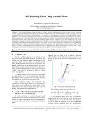
<strong>Finite</strong> <strong>Element</strong> <strong>Analysis</strong> <strong>of</strong> <strong>Helical</strong> <strong>Coil</strong> <strong>Compression</strong> Spring for Three Wheeler Automotive Front SuspensionMax Shear Stress N/Sq. mmFigure 5-Eq. Von Mises Stress CounterEffect <strong>of</strong> Load on the Shear Stress1200.001000.00800.00600.00Theoretical400.00Tet Solid 187200.00Hex Solid 1860.000.0 1000.0 2000.0 3000.0 4000.0Load NREFERENCES[1]. Wahl A. M., “Mechanical Springs”, SecondEdition, McGraw Hill Inc., 1963.[2]. Shigley J. E., Mischke C. R., “MechanicalEngineering Design”, Fifth Edition, McGraw HillInc., 1989.[3]. Prawoto Y., Ikeda M., Manville S. K. andNishikawa A., “Failure analysis <strong>of</strong> automotivesuspension coil springs”, Association for Iron &Steel Technology Proceedings, pp 35-48, 2008.[4]. Dojoong Kim, “Development <strong>of</strong> a finite elementprogram for dynamic analysis <strong>of</strong> helical springs”,Mechanics, Korus, pp309-314, 1999.[5]. Jiang W. J., Henshall J. L., “A novel finiteelement model for helical spring”, <strong>Finite</strong> <strong>Element</strong>sin <strong>Analysis</strong> and Design, Vol. 35, pp 363-377,2000.[6]. Forrester Merville K., “Stiffness model <strong>of</strong> diespring”, M.S. Thesis, Virginia University, 2001.[7]. Berger C., Kaiser B., “Result <strong>of</strong> very high cyclefatigue tests on helical compression springs”,International Journal <strong>of</strong> Fatigue, Vol. 28, pp 1658-1663, 2006.[8]. Al-Mahasne Mayas, Abu Shreehah Tareq A.,“Experimental Investigation <strong>of</strong> polymericcompound cross section spring”, AmericanJournal <strong>of</strong> Applied Sciences, Vol. 4, No. 1, pp 33-36, 2007.Figure 5-Load Vs Shear Stress Effect on Spring1. CONCLUSIONThe elastic behavior and the stress analysis <strong>of</strong> springsemployed in the TWV’s front automotive suspensionhave been presented and discussed in this paper. Theresults obtained by a fully 3D FE analysis alsohighlighted the poor accuracy that can be provided by theclassical spring model when dealing with these springgeometries. Relative errors on maximum shear stressranging from 1.5 to 4 per cent, with reference to theapplied loads, obtained when compared with the valuescalculated by using simple analytical model which isfound in textbooks. The stress distribution clearly showsthat the shear stress is having maximum value at theinner side <strong>of</strong> the every coil. The distribution <strong>of</strong> the stressis similar in every coil. So the probability <strong>of</strong> failure <strong>of</strong>spring in every coil is same except end turns. In suchcase residual stress in every coil may be important factorwhich influence the failure.International Conference on Mechanical and Industrial Engineering133