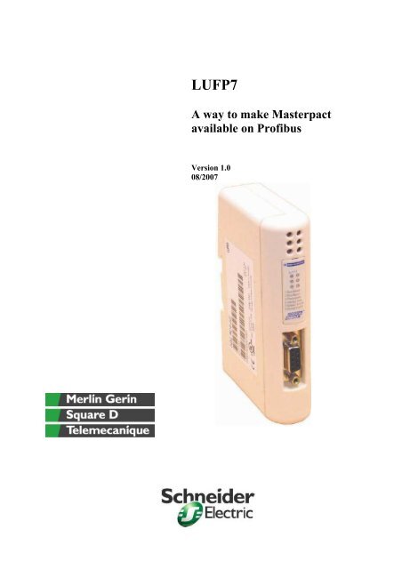
LUFP7 for masterpact & micrologic - Schneider Electric
LUFP7 for masterpact & micrologic - Schneider Electric
LUFP7 for masterpact & micrologic - Schneider Electric

Create successful ePaper yourself
Turn your PDF publications into a flip-book with our unique Google optimized e-Paper software.
Objective of this documentThe aim of this document is to explain how to have Masterpact andCompact NS >630A available on a Profibus network. It does not aim to replace anyuser manual (neither Masterpact Communication nor <strong>LUFP7</strong> user manuals).This document is focused on the <strong>LUFP7</strong> - V2 gateway, which is available on themarket since beginning 2007.Please consider the limitations be<strong>for</strong>e using the <strong>LUFP7</strong> gateway with circuit breakers.3
Safety in<strong>for</strong>mationNoticeRead the device instructions carefully, and look at the equipment to become familiarwith the device be<strong>for</strong>e trying to install, operate, or maintain it. The following specialmessages may appear throughout this documentation or on the equipment to warn ofpotential hazards or call attention to in<strong>for</strong>mation that clarifies or simplifies aprocedure.DisclaimerPlease note:Only qualified personnel should service electrical equipment. No responsibility isassumed by <strong>Schneider</strong> <strong>Electric</strong> <strong>for</strong> any consequences arising out of the use of thismaterial or the associated User Manual. This document is not intended as aninstruction manual <strong>for</strong> untrained persons.© 2007 <strong>Schneider</strong> <strong>Electric</strong>. All Rights Reserved.4
Understanding the Profibus / Modbus gatewayThe <strong>LUFP7</strong> gateway allows a master located on a Profibus-DP network to enter intoa dialogue with the slaves on a Modbus RTU network. This is a generic protocolconverter operating in a way which is transparent to the user.This gateway allows you to interface many products marketed by <strong>Schneider</strong> <strong>Electric</strong>with a Profibus-DP network.The <strong>LUFP7</strong> gateway behaves both as a Profibus-DP slave on the upstream networkand as a Modbus RTU master on the downstream network.The gateway can carry out its data exchanges (inputs and outputs of all types) withthe Modbus slaves cyclically, aperiodically or in an event-driven way. All of theseModbus exchanges make up the gateway’s «Modbus scanner» and we use the«ABC-LUFP Config Tool» software application to configure this scanner’sexchanges. Every item of data exchanged in this way is made available <strong>for</strong> theProfibus-DP master, which can gain access to it in a number of ways (cyclical,aperiodic or event-driven exchange).The Profibus-DP network is totally separate from the Modbus network. The frames ona network are not directly «translated» by the gateway to generate frames on theother network. Instead, the exchanges between the content of the gateway’s memoryand the Modbus slaves make up a system which is independent of the one which isentrusted with managing the exchanges between this same memory and theProfibus-DP master. The system guarantees the coherence of data exchanged withinthe shared memory.5
The following example illustrates the independent management of each of the twonetworks:6
Overview of the <strong>LUFP7</strong> gatewayLegend:1 Detachable power connector <strong>for</strong> the gateway ( 24V ±10%).2 Female RJ45 connector to a PC running ABC-LUFP Config Tool configuration software.3 Female RJ45 connector <strong>for</strong> the downstream Modbus RTU network.4 Six diagnostic LEDs.5 Removable cover <strong>for</strong> the coding wheels used to configure the gateway. The label describing the LEDs is stuckonto this cover.6 Female Profibus-DP connector.7
The gateway uses its own memory map, in order to make the link between Modbusand Profibus networks. The inputs data corresponds to the data coming from Modbusthat will be available on the profibus network; the Output data are the one comingfrom the Profibus network and will be used on the Modbus network. The general dataare used <strong>for</strong> the gateway internal purposes.How does the gateway works?The gateway has its own internal configuration that creates the link between bothnetworks and both data space. When configuring the gateway, you create the link bylinking the functions (read and write) and the memory. E.g. I want the current onphase 1 to be available on profibus, I have to first create the read command in theLUFP configuration, then the response in which I will indicate where I will write theanswer (in the output data), then from profibus I can read the current by sending aread request at the specified address.The important point is that the configuration is fixed, so you have to create offline allthe commands and the mapping. Then to send the configuration to the gateway andonly then you can get data in the profibus network.8
Installation of the gatewayPart numbersPart number <strong>for</strong> purchasing<strong>LUFP7</strong>VW3A8306D30CSD309 (50964)CJB306 (50963)VW3A8106Description:This is the commercial name of the gatewayfrom Profibus to Modbus.This is a 3 meter RJ45 – strip cable. It can beuse from the gateway to the Modbus networkThis is the SubD-9 connector to be used withthe junction boxThis is the junction box to be used to link allthe Modbus slave devicesRS232 to RS485 convertor + RJ45 wiring,used <strong>for</strong> configuration (required once only <strong>for</strong>installation)ModbusModbus and <strong>LUFP7</strong>The <strong>LUFP7</strong> accepts the Modbus read holding registers command (0x03), presetsingle register (0x06) and preset multiple registers (0x10).You can either use the junction box or make a daisy chaining Modbus network. Thewiring is similar to any Modbus network wiring, with 2 wires.MasterpactMasterpactMasterpactMasterpactMasterpactMasterpactMasterpactLink to otherjunction box (if any)9
Please note that the following in<strong>for</strong>mation details the solution with junction box. Thedaisy chain solution can be derived from this.Power SupplyThe <strong>LUFP7</strong> gateway shall be externally power supplied with 24V. This 24V powersupply can be common with the BCM Modbus power supply, if the powerconsumption is compatible (<strong>LUFP7</strong> maximum cunsumption is 95mA with 24V). In anycase, this power supply shall be isolated from the circuit breaker power supply (ifany).Modbus wiring:Overview:Profibus network24VRJ45 – strip wire+ SUBD-9 connectorJunction BlocModbus network10
<strong>LUFP7</strong> Modbus connector:Wire between <strong>LUFP7</strong> and junction box:B (pin4)A (pin5)To <strong>LUFP7</strong>To junction boxBADetailed view of the SUBD-9 connector (male part):9 – A5 – B11
Junction BoxThe junction box shall be 24V power supply, either directly its 24V connector or fromone of the Modbus slave connectors.As the gateway is the Modbus master, it has to be connected to the IN port of thejunction bloc.The <strong>LUFP7</strong> gateway does only provide a Modbus 2 wire network, thus all theModbus slaves shall be compliant with a 2 wire Modbus network. For Masterpact, theBCM is compliant with Modbus 2 wire. If you use the junction box CJB306, then youjust have to put the switch in the “2 wire” position.Please consider the end of line termination, as in a standard Modbus network.If you decide to use your own wiring solution, then the Modbus BCM has to be wiredthis way: (Comm+ correspond to B and Comm- correspond to A).12
ProfibusWiringConnect the SUB-D 9-point male plug on the Profibus-DP connector to the Profibus-DP plug on the <strong>LUFP7</strong> gateway.(1) This signal is not mandatory and may be ignored <strong>for</strong> the <strong>LUFP7</strong> gateway.(2) The “GND” and “+5V” pins are meant to supply the line termination if it is present in theconnector being used.The wiring is a standard Profibus wiring and shall be done as it.13
Profibus configuration of the <strong>LUFP7</strong>This task is limited to configuring the gateway's Profibus address, as thecommunication speed on the Profibus network (9.6 kbits/s to 12 Mbits/s) isautomatically detected by the gateway.The two coding wheels used <strong>for</strong> configuring the gateway’s address are hidden behindthe gateway cover. To remove this cover, insert the end of a small flat screwdriverbetween the top of the hood and the gateway box and pull it out.The <strong>LUFP7</strong> gateway is identified on the Profibus-DP bus by itsaddress, ranging from 1 to 99.This address is the sum of the decimal values given by theangular positions of the bottom coding wheel (tens) and the topcoding wheel (units).The <strong>LUFP7</strong> gateway has no active line termination. You must use a Profibus-DPconnector with such a termination if you place the gateway at one of the ends of abus segment.Mapping:The mapping shall be made manually with the ABC config tool with help of its subnetworkmonitor function. For this you need to know the content of memory neededby each slave and each functions. Then by removing/adding on commands, you canfigure out their address.14
Configuration of the gateway:ABC-Lufp config tool, which is the configuration software <strong>for</strong> the <strong>LUFP7</strong> gateway can bedownloaded from http://www.hms.se/abc_lufp.shtml among with the Lufp7 user guide. Pleasenote that this software shall be installed and used in english in order to allow a suitable importof file (<strong>for</strong> the example we provide).WiringThe <strong>LUFP7</strong> gateway is configured in RS485, so if the configuration is made using a PC, aRS232 to RS485 convertor is required (VW3A8106).15
In case you are using a different converter, the wiring between PC and <strong>LUFP7</strong>configuration port shall be as follow:NOTE: The inversion of the Rx and Tx signals between the gateway and the PC isshown on the 9-point SUB-D connectors, because beyond this junction, the RS-232signals are replaced by the D(A) and D(B) polarizations of the RS-485 signals.PC Com port:There is no need to configure the PC’s COM port, as ABC-LUFP Config Tool uses aspecific setup which replaces the one <strong>for</strong> the port being used. This replacement istemporary and is cancelled as ABC-LUFP Config Tool stops using this serial port,that is to say when ABC-LUFP Config Tool is closed.16
ABC-LUFP config toolThe main window in the ABC Config Tool can be divided in 4 sections as follows:A: Pull-down Menus & Tool BarThe second drop-down menu from the left will change depending on the currentcontext. The Tool Bar provides quick access to the most frequently used functions.B: Navigation SectionThis section is the main tool <strong>for</strong> selecting and altering different levels of the subnetworkconfiguration. Entries proceeded by a ‘+’ holds further configurationparameters or ‘sub menus’. To gain access to these parameters,the entry must be expanded by clicking ‘+’. There are three main levels in thenavigation window, namely Fieldbus, ABC and Sub-network. Right-clicking on entriesin this section brings out additional selections related to that particular entry.C: Parameter SectionThis section holds a list of parameters or options related to the currently selectedentry in the Navigation Section.The parameter value may be specified either using a selection box or manually,depending on the parameter itself.Values can be specified in decimal <strong>for</strong>m (e.g. ‘42’), or in hexadecimal <strong>for</strong>mat (e.g.‘0x2A’).D: In<strong>for</strong>mation SectionThis section holds in<strong>for</strong>mation related to the currently selected parameter.Remark: the configuration can be password protected (File properties or whenconfiguration load), but the password can not be retrieved, so be sure to keep a copyof it in a safe place…17
Detailed properties of the config tool• Fieldbus settings: the fieldbus type is Profibus-DP, as thegateway is between Modbus and Profibus-DP• ABC-LUFP settings:If you want to have the communication statistics onthe Modbus side, you have to enable the statisticsand give a location <strong>for</strong> the counter (in the Input dataside of the memory)• Sub-Network settings: you have to fill in the communicationparameters of your Modbus network (Speed and Parity). Please notethat 8 data bits, RS485 physical standard and 1 stop bits arecompulsory when you have Micrologic.The sub-network shall represent the physical reality of your installation (at least whatyou want to be available on profibus).On right click on the Sub-Network, you can manage yournetwork, either by “sub-network Monitor”, that will display thegateway memory in link with the created nodes and functions orby “sub-network status” that will gives you direct in<strong>for</strong>mation onyour network (available only when gateway is connected). It isalso possible <strong>for</strong> you to add a new Node (Modbus slave), newbroadcaster (broadcast functions) and load an existing node.When you add a new node, you have to specifythe Modbus slave address in its settings. Then onright click on the node name you have variousfunctions.- Node monitor is used to see the gatewaymemory used by this node, to start or stop thisnode and to send any Modbus commands onyou network.- Add command is used to add command(query and response), with guided frame (prefilleddata)- Add transactions is use to add a transaction,which is the same as a command but withoutany help (user has to specify all: the size of the request, its request, all the parts of the rawdata…).18
For each command, you need a query and a response (automatically created whenyou create a new command). The query and response represents most of theModbus raw data (except the property data as error check start byte) (please checkthe annex on Modbus if you need refreshment on this topic).e.g. read slaves 1’s register 661:0x010x030x02940x00010x0000CRCProcess <strong>for</strong> configuration- Open ABC-LUFP config software- Create the configuration (either from scratch or with generic configuration)- Connect the PC to the gateway (wiring + software connection )- Download configuration to the gateway- Check if the configuration is OK (sub-network monitor or node monitor)- Disconnect from the gateway19
Generic configurationsWe provide various configurations that can be used as example in order tounderstand more about how the gateway works and how to configure it. Theseconfigurations shall be evolved in order to suit the customer’s needs, while keeping inmind the restrictions.2 type of file:Configuration file, that represent an existing networkNode file, that represent one Modbus slave (Nodes correspond to Modbus slaves)Using ABC-LUFP config tool software you can either open a configuration file, or inan existing configuration you can insert a node from file (insert from file).Whatever your import choice is, you have to be sure the configuration represents thephysical network (check the address in the node and its commands…). Moreover youhave to be sure that all the nodes either created or imported are compatible withinthe <strong>LUFP7</strong> memory, as each nodes data received or sent are stored in the LUFPmemory (this can be checked using the sub-network monitor: red means collision).We have to configure the Modbus side and its link with profibus.If x is the register written in the Micrologic Modbus guide, x-1 has to be written in theconfiguration tool.If you want to change the name of any node, then press F2.20
Proposed nodesName of thenodeCCM - DevicestatusType ofMicrologicN/A: only CCMContentCCM register661:- connectedposition- disconnectedposition- Test positionInput Areaaddress(Hexadecimal)000 to 001 N/AOutput AreaaddressBCM – CB status AllNode address: 51BCM register661002 to 003 N/ANode address: 1MM – Currents All MM registers1016 to 1022004 to 011 N/ANode address:201MM - Measures P and H MM registers1016 to1022(currents),1000 to1007(voltages),1034 to1045(power) and2000 to2027(energy)004 to 011 (I)012 to 021 (U,V)022 to 039 (P, Q,S)03A to 051 (E)N/ABCM – ControlCommandAllNode address:201Write: 7700 to7704Read: 802 and803052 to 054(commandexecution status)200 to 209Trigger 0x210Node address: 1In the proposed node, the refresh time <strong>for</strong> read is 1s. For the control command, youhave to write first the command (E038 0004 0004 0000 (or 0001) and the password),and then change the trigger byte to anything else than the previous value or 00.Input Area corresponds to all the data that will comes from Modbus slaves to thegateway. Output area corresponds to all the data that comes from profibus master tothe gateway.21
While there are various nodes or various commands in one configuration file, theyare red from up to down (in the ABC-LUFP config tool software view). This isespecially important when you want to write a command, as you have to check theresults after having written the commands.The commands can be sent cyclically, on trigger or on data changed. It isrecommended to have the read commands sent cyclically and the write command onaction (trigger or data change). The refresh / update time can be changed (query /update / Update time), please note that the figure written is in 10ms. In case ofmodifications, you have to verify that your refresh time is not to high in order torespect the physical limitations of Modbus networks.It is possible to have various nodes at the same address, but it is not advisable, asthe software representation will be different from the reality.How to use these nodes - ExampleThese node can be used either directly only in case you have only 1 Micrologic. Incase you have more Micrologic, you have to modify:• The slave address (Node / Slave address); it is recommended to check theslave address not only <strong>for</strong> the node but also <strong>for</strong> each command in order toensure a proper address configuration• The data location (<strong>for</strong> profibus mapping)• For read holding register function: in response / data / data location• For preset multiple register function: in query / data / data location• The trigger byte if anyIt is strongly advised to create a mapping of the profibus address while making the“translation” from generic node to specific node, as it will be necessary <strong>for</strong> you toconfigure your PLC / profibus Master.22
Proposed configurationAll the configurations have been made with parity at even and a baud rate of 19200bps.Read only configurations4 Micrologic: current measures + Breaker statusPlease keep in mind that each 2 Profibus register has to be concatenated in order tocorrespond to 1 Modbus register.16 bytes and 2 commands per <strong>micrologic</strong>Profibus Mapping <strong>for</strong> Micrologic 1(BCM has slave address 1 and Measurementmodule 201):Address Detail0 & 1 Circuit breaker status (from Modbus register 661):Bit 0 (0x01) : OF ; Indication contactsFor Compact and Masterpact : 0= Breaker is opened, 1 = Breaker is closedBit 1 (0x02) : SD ; Trip indication contactFor Compact : 0 = no trip, 1 = Breaker has tripped due to electrical fault or Shunt tripFor Masterpact : always 0Bit 2 (0x04) : SDE ; Fault trip indication contactFor Compact and Masterpact : 0 = no trip, 1 = Breaker has tripped due to electrical faultBit 3 (0x08) : CH ; Charged (used only with motor mechanism)For Compact : always 0For Masterpact : 0 = Spring discharged, 1 = Spring loadedBit 4 (0x10) : Reserved (internal use only)Bit 5 (0x20) : Reserved (internal use only)Bit 6 (0x40) : Compact / Masterpact differentiation0 = Compact NS , 1 = MasterpactBit 7-15 : ReservedNota: A bitmap mask should be used to test the Breaker status.If a value test is used, the following values should be used <strong>for</strong> Masterpact :0x44 Tripped discharged not RTC0x4C Tripped charged not RTC0x50 OFF discharged not RTC0x51 ON discharged not RTC0x59 ON charged RTC0x78 OFF charged RTC2 & 3 RMS current on phase 1 (1016)4 & 5 RMS current on phase 2 (1017)6 & 7 RMS current on phase 3 (1018)8 & 9 RMS current on Neutral (1019)10 & 11 Max RMS current (1020)12 & 13 Ground fault current (1021)14 & 15 Earth leakage current (1022)For all the other Micrologic, the addresses are just translated by 16 (0x10).16 to 31 Micrologic 2 (slave address 2 & 202)32 to 47 Micrologic 3 (slave address 3 & 203)48 to 63 Micrologic 4 (slave address 4 & 204)23
2 Micrologic: current, voltage, energy, power measures + CCM status + Breaker statusProfibus Mapping <strong>for</strong> Micrologic 1(BCM has slave address 1, CCM has address 51and Measurement module 201):Address Detail0 & 1 Device status:Bit 0 (0x01) : OF ; Indication contactsFor Compact and Masterpact : 0= Breaker is opened, 1 = Breaker is closedBit 1 (0x02) : SD ; Trip indication contactFor Compact : 0 = no trip, 1 = Breaker has tripped due to electrical fault or Shunt tripFor Masterpact : always 0Bit 2 (0x04) : SDE ; Fault trip indication contactFor Compact and Masterpact : 0 = no trip, 1 = Breaker has tripped due to electrical faultBit 3 (0x08) : CH ; Charged (used only with motor mechanism)For Compact : always 0For Masterpact : 0 = Spring discharged, 1 = Spring loadedBit 4 (0x10) : Reserved (internal use only)Bit 5 (0x20) : Reserved (internal use only)Bit 6 (0x40) : Compact / Masterpact differentiation0 = Compact NS , 1 = MasterpactBit 7-15 : Reserved2 & 3 Circuit breaker status (from Modbus register 661):Bit 0 (0x01) : OF ; Indication contactsFor Compact and Masterpact : 0= Breaker is opened, 1 = Breaker is closedBit 1 (0x02) : SD ; Trip indication contactFor Compact : 0 = no trip, 1 = Breaker has tripped due to electrical fault or Shunt tripFor Masterpact : always 0Bit 2 (0x04) : SDE ; Fault trip indication contactFor Compact and Masterpact : 0 = no trip, 1 = Breaker has tripped due to electrical faultBit 3 (0x08) : CH ; Charged (used only with motor mechanism)For Compact : always 0For Masterpact : 0 = Spring discharged, 1 = Spring loadedBit 4 (0x10) : Reserved (internal use only)Bit 5 (0x20) : Reserved (internal use only)Bit 6 (0x40) : Compact / Masterpact differentiation0 = Compact NS , 1 = MasterpactBit 7-15 : ReservedNota: A bitmap mask should be used to test the Breaker status.If a value test is used, the following values should be used <strong>for</strong> Masterpact :0x44 Tripped discharged not RTC0x4C Tripped charged not RTC0x50 OFF discharged not RTC0x51 ON discharged not RTC0x59 ON charged RTC0x78 OFF charged RTC4 & 5 RMS current on phase 1 (1016)6 & 7 RMS current on phase 2 (1017)8 & 9 RMS current on phase 3 (1018)0A & 0B RMS current on Neutral (1019)0C & 0D Max RMS current (1020)0E & 0F Ground fault current (1021)10 & 11 Earth leakage current (1022)12 & 13 rms phase-to-phase voltage V1214 & 15 rms phase-to-phase voltage V2316 & 17 rms phase-to-phase voltage V3118 & 19 rms phase-to-neutral voltage V1N24
1A & 1B rms phase-to-neutral voltage V2N1C & 1D rms phase-to-neutral voltage V3N1E & 1F arithmetic mean of the phase-tophase voltages 1/3 x (V12+V23+V31)20 & 21 arithmetic mean of the phase-toneutral voltages 1/3 x (V1N+V2N+V3N).22 & 23 active power on phase 124 & 25 active power on phase 226 & 27 active power on phase 328 & 29 Total active power2A & 2B reactive power on phase 12C & 2D reactive power on phase 22E & 2F reactive power on phase 330 & 31 total reactive power32 & 33 apparent power on phase 1 with 3 wattmeters34 & 35 apparent power on phase 2 with 3 wattmeters36 & 37 apparent power on phase 3 with 3 wattmeters38 & 39 total apparent power3A & 3B total active energy part1 (mod10000)3C & 3D total active energy part23E & 3F total active energy part340 & 41 total active energy part442 & 43 total reactive energy part1 (mod10000)44 & 45 total reactive energy part246 & 47 total reactive energy part348 & 49 total reactive energy part44A & 4B total apparent energy part1 (mod10000)4C & 4D total apparent energy part24E & 4F total apparent energy part350 & 51 total apparent energy part452 & 53 Status command register Open54 & 55 Status command register Close00 to 55 Micrologic 1 (slave address 1, 51 & 201)60 to B5 Micrologic 2 (slave address 2, 52 & 202)The second Micrologic parameters have to be derived from the table above(translation by 0x55)Profibus mapping <strong>for</strong> the out area (to be written by Profibus master - control command)Address Detail0 & 1 0xE038 (57400) (command number <strong>for</strong> open or close)2 & 3 P1 = 0004 (total number of parameters including P1)4 & 5 P2 = 0004 (circuit-breaker manager)6 & 7 P3 = 0000 <strong>for</strong> Open or P3 = 0001 <strong>for</strong> Close8 & 9 P4 = Password (default value = 0000)0A to 0F free10 Trigger byte <strong>for</strong> Micrologic 111 to 1F free20 & 21 0xE038 (57400) (command number <strong>for</strong> open or close)25
22 & 23 P1 = 0004 (total number of parameters including P1)24 & 25 P2 = 0004 (circuit-breaker manager)26 & 27 P3 = 0000 <strong>for</strong> Open or P3 = 0001 <strong>for</strong> Close28 & 29 P4 = Password (default value = 0000)2A to 2Ffree30 Trigger byte <strong>for</strong> Micrologic 2To send the command the various step has to be followed:- write the command parameters (from 00 to 09)- change the trigger byte (make it different to 0 and to the previous value)(These both steps can be achieved through 1 Profibus commands)26
How to use these configurationsYou can use these configurations as they are, or modify them. When you make amodification, you have to be very careful with the mapping and ensure that there is nooverlapping. This can be verified using sub-network monitor, where no red shall be displayed.The ABC-LUFP config tool can also be used to check the Modbus value of the registers andcheck that the configuration is well done and used.<strong>LUFP7</strong> has some Led that have to be checked <strong>for</strong> debugging and ensuring the configurationworks fine (only from protocol standpoints).27
Create configuration from scratchIn order to avoid problems:• Create as many node as needed (one node is a Modbus slave)• Give the Modbus address to all nodes• Create the commands with adequate parameters• 1 Modbus register corresponds to 4 hexadecimal digits. That is 2 Bytes• Query and respond correspond to the Modbus raw data (see annex <strong>for</strong>more on Modbus raw data)If you create your own node, you have to be sure that the response is correctlyconfigured, even if you don’t need to have this response (this is typically the casewhen you write a command). In case the response is not the expected one, then the<strong>LUFP7</strong> will decide to re-send the command (this could create problems <strong>for</strong> “ontrigger” or “on state of data change” commands).<strong>LUFP7</strong> uses register numbers, whereas the Modbus guide <strong>for</strong> Micrologic gives theregister address. Thus 1 shall be deduct from each address (e.g. 7700 commandregister in Modbus guide correspond to 7699 in the <strong>LUFP7</strong> gateway).28
Limitations of the gatewayThe gateway will create a bridge between Profibus and Modbus, as this link is hardcoded,it create some memory limitations:- The sum of Input Data and Output Data is limited to 416 bytes max.- Maximum slave number is 8 (this is less <strong>for</strong> Micrologic, as it is composed ofvarious slave).- Maximum transactions of 100 (this is 50 Modbus commands)- Maximum memory of 512 Bytes (244 bytes of inputs data and 244 bytes of outputdata)Moreover, as the gateway will act in the Modbus network as a master and as a slavein the Profibus network, it is impossible to have another master in the Modbusnetwork.As Modbus network will be cyclically polled, keep in mind that every Modbuscommand takes time on the bus be<strong>for</strong>e asking <strong>for</strong> a high refresh time. In case therefresh time is to high, the gateway could not follow it, but will act as fast as possible(minimum stop time between transactions). As the Lufp7 cyclically polls theMicrologic, data in its memory that will be given to the profibus master can bedifferent from the real-time value. This time difference mostly depends on the numberof Micrologic and the number of data requested <strong>for</strong> each (see addendum <strong>for</strong> delaycalculation).If we the time constraints is less real are and if data we want from Micrologic are notspecific (available in the communication profile), we could link the gateway with thecommunication profile located in the BCM, then we can have 8 Micrologic connectedto one single <strong>LUFP7</strong>. Do not <strong>for</strong>get that communication profile needs to be activatedbe<strong>for</strong>e use.You must check that the size of the Profibus-DP data corresponds to the size of thememory used <strong>for</strong> the Modbus exchanges, because the gateway configures itsProfibus-DP exchanges on the basis of the memory used by the Modbus frames. Ifthe sizes do not match, the fieldbus Diag LED n°4 b links at 1 Hertz frequency, cyclicModbus exchanges are enabled and write-access Modbus registers are set to 0.29
Addendum 1: More on Modbus protocol:More on Modbus (function 3 /16): read + WriteModbus function 3 and 16 are supported by the gateway.Function 3: read holding registersRequest2 bits 2 bits 4 bits 4 bits 4 bitsSlave addressFunction code(03)Address of the 1 stregister requestedTotal number ofregister requiredCRCResponse2 bits 2 bits 2 bits 4 bitsSlave address Function code Number of Content of register written CRC(03) byte to follow(1 register = 2Bytes)Function 16: preset multiple registersRequest:2 bits 2 bits 4 bits 4 bits 2 bits 4 bitsSlaveaddressFunctioncode (16= 0x10)Dataaddress ofthe 1 stregister towriteNumberof registerto writeNumberof databytes tofollow(normallynr of reg *2)Value to writeResponse:2 bits 2 bits 4 bits 4 bits 4 bitsSlave address Function code(16)Address of the 1 stregisterNumber ofregisters writenCRCCRC30
Addendum 2: data time-reliability calculationThe following figure comes from average figures and shall be used only as time reference, asin some specific cases the delay values can be much higher.The aim is to understand / calculate the maximum time difference between the measures thathave been red and the real/physical value.After the <strong>LUFP7</strong> has send a Modbus read command to Micrologic (measures or protections):PhysicalvaluesMicrologicregistersBCMregisters<strong>LUFP7</strong>registersProfibusMasterregistersRefresh time:1secondMaximumread time:200 msMaximumread time:50 msIn case of a read command to the BCM like breaker status, the delay between the physicalswitch value and the Modbus availability is 200ms.In case of a read command to the BCM without any query to Micrologic, the delay is 50ms.The <strong>LUFP7</strong> will poll continuously on Modbus; this means that as soon as it receives theanswer from a slave it will send the next message.In case of 4 Micrologic from which you want to read the measures and the breaker status:The following command will be sent on the bus:- Read current Micrologic 1 (250ms)- Read current Micrologic 2 (250ms)- Read current Micrologic 3 (250ms)- Read current Micrologic 4 (250ms)- Read status Micrologic 1 (50ms)- Read status Micrologic 2 (50ms)- Read status Micrologic 3 (50ms)- Read status Micrologic 4 (50ms)The <strong>LUFP7</strong> will then poll the data again after 1.2 seconds. Thus the data in itsmemory(available on Profibus) will be maximum 2.2 seconds “old”.In case of 8 Micrologic from which we read data from the communication profile:The following commands will be sent on the bus:- Read data from Micrologic 1 (50ms)- Read data from Micrologic 2 (50ms)- Read data from Micrologic 3 (50ms)- Read data from Micrologic 4 (50ms)- Read data from Micrologic 5 (50ms)31