iTest+® GPS PicoReference⢠Spec - Spectratime
iTest+® GPS PicoReference⢠Spec - Spectratime
iTest+® GPS PicoReference⢠Spec - Spectratime

You also want an ePaper? Increase the reach of your titles
YUMPU automatically turns print PDFs into web optimized ePapers that Google loves.
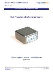
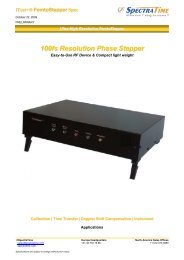
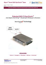
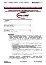
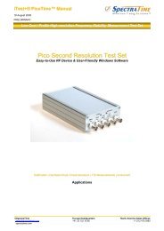
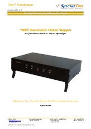
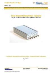
iTest+® <strong>GPS</strong> PicoReference <strong>Spec</strong>7 th January 2010Low Cost, Pico Resolution <strong>GPS</strong>/Rb Reference Test SetPico Second Resolution Test SetEasy-to-Use RF Device & Compact light weightCalibration | Oscillator/Clock Characterization | TIE Measurements | InstrumentApplications©<strong>Spec</strong>traTime Europe Headquarters North America Sales Officessales@spectratime.com +41.32.732.16.66 +1.512.470.3980spectratime.com<strong>Spec</strong>ifications are subject to change without prior notice
iTest+® <strong>GPS</strong> PicoReference <strong>Spec</strong>KEY FEATURES• <strong>GPS</strong> disciplined Rb clock• Power supply voltage• Compact• Testing Frequency Range• Reference Frequency• Phase time resolution and noise• Output Frequency• User programmable SYNTH output• Integrated smart auto calibration• Internal Bit Alarm• RS232 standard interface• Software• <strong>GPS</strong> antenna types: Auto-adaptive SmarTiming+ loop timeconstant, running at 1ns resolution: AC input 85-264VAC / 47-63Hz: 1U rack mount chassis: 1-30 MHz: Integrated <strong>GPS</strong>-locked Rubidium clock: ≤ 2ps rms: 4x 10MHz / 4x 1PPS or 8 x 10 MHz: 9600 b/s: Windows 98, XP: Patch or rooftop©<strong>Spec</strong>traTime Europe Headquarters North America Sales Offices Page 2 of 13sales@spectratime.com +41.32.732.16.66 +1.512.470.3980spectratime.com
iTest+® <strong>GPS</strong> PicoReference <strong>Spec</strong>SPECIFICATIONSELECTRICAL<strong>Spec</strong><strong>GPS</strong> PicoReferenceReference module Standard OptionsRFOUT Frequency10MHz10MHzNumber of Output 4x backplane1x faceplate8x backplane1x faceplatePPSOUTShort Term StabilityPhase Noise (dBc/Hz)(RFOUT: 10 MHz)FunctionalityNumber of OutputAging(Measured after 3 months of continuous operation)Frequency Retrace1s10s100s1Hz10Hz100Hz1kHz10kHzOff/On(In stable temperature, gravity, pressure andmagnetic field conditions)RFOUT LevelsOutputSYNTHESIZER (SYNTH)<strong>GPS</strong> Antenna ConnectorImpedanceHarmonicsSpurious f 0 ± 100kHz (SYNTH Off)Output levelFrequency rangeResolutionSpurious1PPSSee SmarTiming section4x backplane1x faceplate3E-111E-113E-12(ordering code: 8RF)1PPS(ordering code: 8RF)1x faceplate(ordering code: S)1E-113E-121E-12(ordering code: S)-80-100©<strong>Spec</strong>traTime Europe Headquarters North America Sales Offices Page 3 of 13sales@spectratime.com +41.32.732.16.66 +1.512.470.3980spectratime.com-75-95-125-145-145< 5E-11 / month(typical: 3E-11 / month)< 5E-1124 hr / 1 hrSine wave, 0.5 Vrms (±10% / 50 Ω), 1x faceplate**Sine wave, 1.0 Vrms (±10% / 50 Ω), 4x backplane(** ordering code: 8RF 8x)50 Ω ±20%< -25dBc< -80dBcSquare wave 3.3V LV CMOS0 to 20 MHz3.97mHz (Fout= N×60’000’000/2 32 )-35dBc (1-10 MHz)-30dBc (10-20 MHz)SMAMeasurement moduleStandard versionReference Frequency10 MHzDUT Center Frequency Range1 MHz – 30 MHzClock Recovery circuitE1 & T1Measurement Noise @10MHz (Maximum Relative< 2psFrequency Deviation During Measurements < 1x10 -9 )Measurement Noise @10MHz (Maximum Relative< 10psFrequency Deviation During Measurements < 1x10 -7 )Typical System Noise @10MHzSee typical measurement figure 1(± 2°C temp. Change during measurement)Input Signal Level+3 dBm to +17 dBmInput Impedance 50 Ohms ±20%Connectors TypeBNCPC PortStandard 9600 b/s – Serial (COM1 or COM2 orCOM3 or COM4)
iTest+® <strong>GPS</strong> PicoReference <strong>Spec</strong>SMARTIMING+ ® FUNCTIONALITY<strong>Spec</strong>PPSOUTOutput levelPulse width (PW) or duty cyclePPSOUT to PPSREF Sync ErrorIn Sync modePPSOUT to PPSREF (DE)Programmable delay (In Track mode)PPSOUT Holdover Time StabilitySmart Loop Time ConstantPhase/FrequencyUser settable<strong>GPS</strong> PicoReferenceStandard1PPSCMOS 0-5V (+- 20 mA sink/source)User settable, 0 to 1s in 133ns/step< 50 nsNo <strong>GPS</strong> PPSRef noise, ± 1°C temp fluctuations0 to 1 s in 133 ns stepsWithin ± 2°C 1 µs/24 hrAuto-adaptive 1000 to 100,000 secUser settable Sync/Track mode **Selected by RS232 interface** Sync: phase/time alignment; Track: frequency alignment<strong>GPS</strong> ANTENNAAntenna Types<strong>Spec</strong>Cable LengthLightening Surge Protector<strong>GPS</strong> PicoReferenceStandardOptionPatch antenna kit Rooftop antenna kit6 m / 19.7’5+15m / 16.4’ + 49’Not applicableIncluded(ordering code: RA)POWER<strong>Spec</strong>Power SupplyPower Input FluctuationInput FrequencyPower Consumption @25°CConnector Type<strong>GPS</strong> PicoReferenceStandardAC input 85-264VAC±10% of nominal supply voltage (230V~)47 – 63 HZ< 25W after warm-upIEC plugENVIRONMENT<strong>Spec</strong><strong>GPS</strong> PicoReferenceStandardOperating Temperature 0 to 40°C(Relative humidity: 10-85%)Storage -25 to 55°CTransportation -25 to 70°CPHYSICAL<strong>Spec</strong><strong>GPS</strong> PicoReferenceStandardOptionSize445 x 300 x 44 mm (1U)Weight2.2 KgMounting Tabletop feet 19” rack mountable ears(ordering code: E)©<strong>Spec</strong>traTime Europe Headquarters North America Sales Offices Page 4 of 13sales@spectratime.com +41.32.732.16.66 +1.512.470.3980spectratime.com
iTest+® <strong>GPS</strong> PicoReference <strong>Spec</strong>The <strong>GPS</strong> PicoReference includes 2 modules: a Frequency Reference module and a Measurementmodule.REFERENCE MODULE DESCRIPTIONThe module integrates a smart Rubidium atomic clock and a <strong>GPS</strong> receiver. It has 3 basic modes ofoperation: Free Run, Track and Sync. The Free Run mode is when the Rubidium clock is not lockedto a reference, and thus free running. The Track mode is when the reference is used to performfrequency alignment applications, whereas the Sync mode is when the reference is used to performphase alignment applications.As illustrated in Figure 1, when the module works in Track mode it uses the PPS_<strong>GPS</strong> as a reference(PPSREF) to align the frequency of the Rubidium clock. The frequency alignment is computed by aninternal phase-time error signal that is generated by an internal PPS signal (PPSINT), whichmeasures the signal at 1ns resolution through its SmarTiming+ technology. The PPSINT thenaligns the PPSREF phase.In the Sync mode, the reference module phase aligns the PPSOUT to the PPSREF with the PPSINTreference signal, which uses SmarTiming+ algorithm to 1) compare the PPSOUT and PPSREFsignals at 1ns resolution within a +/-500ns dynamic range and 2) auto-adaptively align them.The module has also the capability to dynamically analyze the stability of the PPSREF signal throughthe excellent mid-term frequency stability of the Rubidium technology. Thus, the 1PPS-<strong>GPS</strong>reference can be directly fed to the Rubidium clock without specific analysis of the internaloptimization parameters of the <strong>GPS</strong> engine - i.e., number of satellites in view, signal to noise ratio,etc.Figure 2 illustrates the typical frequency stability performance of the reference module, using its builtin10MHz Rubidium reference clock.Normal initialsituationIn free-run
iTest+® <strong>GPS</strong> PicoReference <strong>Spec</strong>Frequency Adjustments & Rb Loop Monitoring FunctionsThe working and monitoring parameters of the Frequency Reference module are accessible for readand write operations through the serial RS-232 port (9600 bits/sec., no parity, 1 start bit, 8 data bits, 1stop bit).There are 2 basics commands as follows: M and CxxxxM: monitors the basic internal signals of the atomic clock.The returned answer is:HH GG FF EE DD CC BB AA Of which each returned byte is an ASCII coded hexadecimal value, separated by a character. All parameters are coded at full scale.HH: Read-back of the user provided frequency adjustment voltage on pin 2 (0 to 5V)GG: reservedFF: peak voltage of Rb-signal (0 to 5V)EE: DC-Voltage of the photocell (5V to 0V)DD: varactor control voltage (0 to 5V)CC: Rb-lamp heating current (Imax to 0)BB: Rb-cell heating current (Imax to 0)AA: reservedCxxxx: output frequency correction through the synthesizer, by steps of 5.12 × 10 -13 ,where xxxx is a signed 16 bits word in hexa coded ASCII. This value is automatically stored in aEEPROM as last frequency correction which is applied after RESET or power-ON operation.In Track mode this correction is not in use. The function FCsddddd does the same, but the dataformat is different.There is a command to set the SYNTH output frequency:Txxxxxxxx: Where xxxxxxxx is an unsigned 32 bits in hexa coded ASCII stored inxxxxxxxxEEPROM. The frequency is changed after a reset Frequency = ⋅60MHz2 32©<strong>Spec</strong>traTime Europe Headquarters North America Sales Offices Page 8 of 13sales@spectratime.com +41.32.732.16.66 +1.512.470.3980spectratime.com
iTest+® <strong>GPS</strong> PicoReference <strong>Spec</strong>Timing & Locking Control CommandsUsing the same data interface, the Reference module can accept the following basic ASCIIcommands: Data is in decimal ASCII code.CommandnameSyntaxcommandData field(if any)ResponsesyntaxIdentification ID - TNTSRO-aaa/rr/s.ssResponse data(if any)aaa: 100rr: revision numbers.ss: software versionSerial number SN - xxxxxx xxxxxx : 6 digits serial nbrStatus ST - s s:Statuss=0 :warming ups=1 :tracking set-ups=2 :track to PPSREFs=3 :synch to PPSREFs=4 :Free Run. Track OFFs=5 :FR. PPSREF unstables=6 :FR. No PPSREFs=7 :factory useds=8 :factory useds=9 :fault or Rb OOLSet TrackingPPSINT -PSSREFSetSynchronisationPPSOUT –PPSINTSet PPSOUTdelaySet PPSOUTPulse WidthTRxSYxDEdddddddPWdddddddx=0 : Track neverx=1 : Track nowx=2 : Track everx=3 : Track now + everx=9 : InterrogationX=0 : Synch. neverx=1 : Synch. nowx=2 : Synch. everx=3 : Synch. now + everx=9 : Interrogationddddddd=delay by 133nsstep. Max 7499999DE0000000 :synch toPPSREFddddddd=pulse Width by133ns step. Max 7499999PW0000000: no pulsexxddddddddddddddx:Tracking commands statusx=0 : Track OFFx=1 : Track ON(when Status 9 -> 4x:Sync. commands statusx=0 : Synch. OFFx=1 : Synch. ON(When Status 1 -> 2)Time of day TD - hh:mm:ss hh:hoursmm:minutesss:secondsSet time of day TDhh:mm:ss hh:Hoursmm:Minutesss:secondshh:mm:ssddddddd=delay by 133ns step.Max 7499999ddddddd=Pulse Width by 133nsstep. Max 74999990000000: no pulsehh:hoursmm:minutesss:secondsDate DT yyyy-mm-dd yyyy : yearmm : monthdd : daySet dateBeat everysecondon serial port.Set frequencyadjustmentDT yyyy-mm-ddBTxFCsdddddyyyy : yearmm : monthdd : dayx=0 : Stop beatx=1 : Effective Time intervalPPSOUT vs PPSREFx=2 : Phase comparatorx=3 : Both x=1 & x=2x=4 : Beat Time of dayx=5 : Beat statusx=6 : Beat x=7 : Beat Date, Time, Statusx=A : Beat NMEA $PTNTA,x=B : Beat NMEA $PTNTS,B,s=+/- signeddddd = limited within range: +32767/-32768FC+99999 : interrogationyyyy-mm-ddddddddd orsppp orddddddd sppp orhh:mm:sssyyyy-mm-dd hh:mm:ss ssdddddyyyy : yearmm : monthdd : dayddddddd : delay in 133nsstepsppp:phase error in nss: +/- signehh:hours mm:minutesss:secondess: statusyyyy:year, mm:month,dd:days: +/- signeddddd : frequ. Adj. in5.12 x 10 -13 step©<strong>Spec</strong>traTime Europe Headquarters North America Sales Offices Page 9 of 13sales@spectratime.com +41.32.732.16.66 +1.512.470.3980spectratime.com
iTest+® <strong>GPS</strong> PicoReference <strong>Spec</strong>CommandnameSet frequencysave. Integralpart, when Status= 2, 3Set TrackingWindowSet no AlarmWindowSet trackingphase loop timeconstantSet modulecustomizationSet phasecomparatorOffsetSyntaxcommandFSxTWdddAWdddTCddddddMCsxx [cc…c]COsdddData field(if any)x=0 : never savex=1 : save every 24 hoursx=2 : save right nowx=3 : save actual freq. nowx=9 : interrogationddd = Half Tracking Windowby 133ns step.From 1 to 255ddd = 999 : interrogationddd = Half no Alarm Windowby 133ns step.From 1 to 255ddd = 999 : interrogationdddddd = Time constant inseconds (001000 to 999999)TC000000 : change to auto.(
iTest+® <strong>GPS</strong> PicoReference <strong>Spec</strong>MEASUREMENT MODULE DESCRIPTIONThis module is based on a heterodyne architecture with a double frequency conversion to reach aresolution around the pico-second level. The following figure shows the typical system noise. Themodule integrates autonomous software, enabling the <strong>GPS</strong> PicoReference to work with an external10MHz reference or through its built-in 10MHz reference module. The flexible testing frequency rangeis any frequencies between 1 - 30 MHz.Additionally, the following 3 outputs are available to perform extra measurements using an externalfrequency counter:• 1KHz output, using a crystal-filter based PLL to restrict the bandwidth to only 1Hz• 1KHz output, providing about 100KHz bandwidth• 1PPS outputThe module also contains a clock recovery interface circuit. It extracts the clock rate of a E1(2048KHz) or T1 (1544KHz) line in order to be able to measure it with the measurement module.Figure 3 - Noise Measurement Performance @10MHz©<strong>Spec</strong>traTime Europe Headquarters North America Sales Offices Page 11 of 13sales@spectratime.com +41.32.732.16.66 +1.512.470.3980spectratime.com
iTest+® <strong>GPS</strong> PicoReference <strong>Spec</strong>MECHANICAL LAYOUTI/O INTERFACES©<strong>Spec</strong>traTime Europe Headquarters North America Sales Offices Page 12 of 13sales@spectratime.com +41.32.732.16.66 +1.512.470.3980spectratime.com
iTest+® <strong>GPS</strong> PicoReference <strong>Spec</strong>Back PanelN° Type Definition I/OJ1 SMA <strong>GPS</strong> antenna connection IJ2 SUB-D9-F Reference module Serial communication RS232 I/OJ3-J6 BNC 4x 10MHz sine reference outputs OJ7-J10 BNC 4x 1PPS outputs (4x 10 MHz sine reference outputs with option code 8RF) OJ11 SUB-D9-F Measurement module Serial communication RS232 I/OJ12 IEC PLUG Power connection IS1 SWITCH On/Off switch -Front PanelN° Type Definition I/OJ13 BNC Measurement module 10MHz reference IJ14 BNC Measurement module 1PPS reference for external counter OJ15 BNC 1KHz filtered for external counter OJ16 BNC 1KHz non filtered for external counter OJ17 BNC Device under test input signal IJ18 BNC 10MHz sine reference output OJ19 BNC 1PPS output OJ20 BNC SYNTH output OJ21 BNC insulated E1 clock recovery input IJ22 BNC E1 clock recovery output OJ23 BNC insulated T1 clock recovery input IJ24 BNC T1 clock recovery output OI1 Green LED Measurement module locked indicator -I2 Red LED Measurement module unlocked indicator -I3 Green LED Power indicator -I4 Green LED Sync or Track mode enabled -I5 Red LED Rubidium clock locked alarm -I6 Green LED 1PPS <strong>GPS</strong> applied -S2 SWITCH Free run, Sync or track selection switch -©<strong>Spec</strong>traTime Europe Headquarters North America Sales Offices Page 13 of 13sales@spectratime.com +41.32.732.16.66 +1.512.470.3980spectratime.com