iSource+⢠Low Cost HPFRS Manual - Spectratime
iSource+⢠Low Cost HPFRS Manual - Spectratime
iSource+⢠Low Cost HPFRS Manual - Spectratime

Create successful ePaper yourself
Turn your PDF publications into a flip-book with our unique Google optimized e-Paper software.
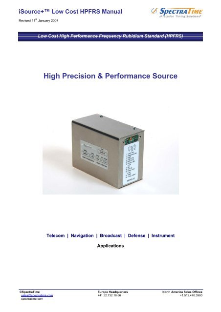
iSource+ <strong>Low</strong> <strong>Cost</strong> <strong>HPFRS</strong> <strong>Manual</strong>Revised 11 th January 2007<strong>Low</strong> <strong>Cost</strong> High Performance Frequency Rubidium Standard (<strong>HPFRS</strong>)High Precision & Performance SourceTelecom | Navigation | Broadcast | Defense | InstrumentApplications©SpectraTime Europe Headquarters North America Sales Officessales@spectratime.com +41.32.732.16.66 +1.512.470.3980spectratime.com
iSource+ <strong>Low</strong> <strong>Cost</strong> <strong>HPFRS</strong> <strong>Manual</strong>Table of Content :1. INTRODUCTION ..............................................................................................................................................................32. LPFRS SYSTEM DESCRIPTION.....................................................................................................................................32.1 PRINCIPLE OF OPERATION AND BASIC CONFIGURATION.................................................................32.2 PHYSICS PACKAGE ..................................................................................................................................42.3 ELECTRONICS PACKAGE ........................................................................................................................52.3.1 PRINCIPAL FUNCTIONS OF THE ELECTRONIC CIRCUITS ............................................................53. <strong>HPFRS</strong> SPECIFICATIONS...............................................................................................................................................84. <strong>HPFRS</strong> INSTALLATION AND OPERATION ...................................................................................................................84.1 INTRODUCTION..........................................................................................................................................84.2 SHIPPING AND RECEIVING INFORMATION............................................................................................84.3 MOUNTING..................................................................................................................................................84.4 PIN FUNCTION LAYOUT..........................................................................................................................104.5 NORMAL OPERATION.............................................................................................................................104.6 SERIAL INTERFACE OPERATION..........................................................................................................114.6.1 INTRODUCTION ................................................................................................................................114.6.2 SERIAL INTERFACE CONNECTION ................................................................................................114.6.3 <strong>HPFRS</strong>-02 INTERNAL PARAMETERS MONITORING .....................................................................114.6.4 CENTRE FREQUENCY ADJUSTMENT WITH THE SERIAL INTERFACE ......................................114.6.5 CENTRE FREQUENCY READ-BACK ...............................................................................................124.7 <strong>HPFRS</strong>-01 LOCK MONITOR and XTAL MONITOR OUTPUTS ..............................................................124.7.1 ‘LOCK MONITOR’ FUNCTIONAL DIAGRAM GENERATION............................................................124.7.2 XTAL MONITORING OUTPUT:..........................................................................................................124.7.3 LAMP MONITORING..........................................................................................................................134.8 <strong>HPFRS</strong>-02 LOCK MONITOR ....................................................................................................................134.8.1 TTL OR CMOS LEVEL ‘LOCK MONITOR’ GENERATION:...............................................................13©SpectraTime Europe Headquarters North America Sales Offices Page 2 of 13sales@spectratime.com +41.32.732.16.66 +1.512.470.3980spectratime.com
iSource+ <strong>Low</strong> <strong>Cost</strong> <strong>HPFRS</strong> <strong>Manual</strong>1. INTRODUCTIONThe Models <strong>HPFRS</strong> XX Rubidium Ultra-Stable Oscillators are sub-miniature, atomic resonance-controlledoscillators that provide an extremely stable frequency of 10 or 20 MHz (sinusoidal). The <strong>HPFRS</strong> is designed fornavigation , communication and timing instruments requiring such extremely stable and precise frequency.This manual contains information about the operation and field maintenance of the <strong>HPFRS</strong>.Chapter 2 contains a general description of the unit. It also presents a basic theory of operation for a technicianor engineer who requires a better understanding of the unit's operation.Chapter 3 lists all specifications and operation requirements of the <strong>HPFRS</strong>.Chapter 4 gives information on how to install and operate the unit. It is recommended that these chapters beread prior to operate the unit. This chapter describes also the possible interface connection for the monitoring ofthe internal parameters and for the centre frequency adjustment.2. LPFRS SYSTEM DESCRIPTION2.1 PRINCIPLE OF OPERATION AND BASIC CONFIGURATIONThe <strong>HPFRS</strong> essentially consists of a voltage-controlled crystal oscillator (VCXO) which is locked to a highlystable atomic transition in the ground state of the Rb 87 isotope. While the frequency of the VCXO is at theconvenient standard frequency of 10 MHz, the Rb clock frequency is at 6.834XXX GHz in the microwave range.The link between the two frequencies is done through a phase-stabilized frequency multiplication schemewhereby a synthesized frequency is admixed to enable exact matching.The Rb atoms are confined in a vapor cell at an elevated temperature. The cell is placed in a microwaveresonator to which the microwave power derived from the VCXO is coupled. The Rb 87 atoms in the cell occurwith equal probability in the two hyperfine energy levels of the ground state (F=1 and F=2).In order to detect the clock transition between these two levels, the atoms need to be manipulated in such away that most of them occur in only one level. This is done by optical pumping via a higher lying state (P). Fig.2-1 visualizes the atomic energy levels and transitions involved in the optical pumping process.Fig. 2-1: Energy levels and transitions in Rb 87 atoms during <strong>HPFRS</strong> operation©SpectraTime Europe Headquarters North America Sales Offices Page 3 of 13sales@spectratime.com +41.32.732.16.66 +1.512.470.3980spectratime.com
iSource+ <strong>Low</strong> <strong>Cost</strong> <strong>HPFRS</strong> <strong>Manual</strong>The pump light comes from a Rb resonance lamp which emits the light of Rb 87 atoms. This light, whichintersects the absorption cell, is filtered in such a way that mainly one optical frequency, which corresponds to atransition out of one of the two ground state levels (line A), enters the principal absorption region.The pump light excites Rb 87 atoms which are in the lower hyperfine level (F=1) to the short-lived excited state Pfrom which they decay to the two ground state levels (F=1,2) with equal probability. Since pumping occurscontinuously out of the F=1 level, after some time, almost all atoms are found in the F=2 level and no furtherabsorption occurs.The transmitted light level is detected by a photodiode after the cell. If now a microwave field resonant withclock transition F=2® F=1 is coupled to the interaction region, the level F=1 is repopulated and light absorptionis enhanced. A sweep of the microwave field over the resonance is detected as a small dip in the transmittedlight level after the cell.This signal is fed into a synchronous detector whose output generates an error signal which corrects thefrequency of the VCXO when its multiplied frequency drifts off the atomic resonance maximum.The absorption cell is filled with metallic vapor which contains Rb 85 and Rb 87 isotopes and a buffer gas. Filteringof the pump light is achieved in the entrance region of the cell by absorption with Rb 85 atoms which have anaccidental overlap with one of the Rb 87 resonance transitions (line B): integrated filter cell.Fig. 2-2: Rubidium atomic clock principal block diagramThe principal function of the buffer gas is to keep the Rb atoms away from the cell walls and restrict theirmovements. As a result they are practically "frozen in place" for the interaction time with the microwave field. Inthis way the Doppler-effect is virtually removed and a narrow line width results.The cell region is also surrounded by a so-called C-field coil which generates a small axial static magnetic fieldto resolve the Zeeman sub-transitions of the hyperfine line and select the clock transition, i.e. the one with theleast magnetic sensitivity. To further reduce the magnetic sensitivity, the complete physics package is placedinto nested magnetic shields.Fig. 2-2 gives a basic overview of the different function blocks of the Rubidium atomic clock. The <strong>HPFRS</strong>consists of three different packages. The optical elements, which include the Rb absorption cell and microwavecavity, form the atomic resonator, while the electronics package is constituted of the generator and thedetection circuitry.2.2 PHYSICS PACKAGEThe main design characteristics of the physics package are its low power consumption, small size and mass,along with minimal environmental sensitivities and mechanical ruggedness.All parts of the physics package are incorporated in a aluminium tube surrounded by magnetic shields. Insidethis tube, lamp and cell sections form two separate blocks which operate at well-defined but differenttemperatures. The cylindrical tube is filled with polyurethane foam for low thermal conductivity. The lamp andcell sections are separated with a glass window. This configuration greatly reduces the thermal flow between©SpectraTime Europe Headquarters North America Sales Offices Page 4 of 13sales@spectratime.com +41.32.732.16.66 +1.512.470.3980spectratime.com
iSource+ <strong>Low</strong> <strong>Cost</strong> <strong>HPFRS</strong> <strong>Manual</strong>the blocks and the tube envelope. It allows a very compact design with low power consumption, short warm-uptime and minimal environmental sensitivities.Other design features which contribute to the compact design are:- use of the integrated filter technique (IFT)- use of a magnetron-type microwave resonatorThe integrated filter technique which combines the optical filtering and pumping in one cell contributes also tothe reliability since the configuration is simplified and the number of components reduced. The thermalcapacitance of the cell assembly is relatively low. As a consequence, the necessary power during warm-up isgreatly reduced.The magnetron resonator is a cylindrical cavity loaded with a concentric capacitive-inductive structure (annularmetal electrodes). It allows smaller cavity dimensions and concentrates the microwave field at the right regionof the cell.The Rb lamp is an electrode-less RF-discharge lamp: a heated glass bulb which contains Rb and a starter gassurrounded by an RF-coil.Although the atomic clock transition frequency is inherently quite stable, there are second order influenceswhich affect the frequency, i.e. temperature (buffer gas), light intensity (light shift = optical Stark effect),magnetic field (2nd order Zeeman effect). As a consequence, the temperatures of lamp and cell, the power ofthe lamp oscillator and the current in the C-field coil have to be carefully stabilized.2.3 ELECTRONICS PACKAGE2.3.1 PRINCIPAL FUNCTIONS OF THE ELECTRONIC CIRCUITSThe clock transition of a Rb resonator is a microwave transition at 6.834 .. GHz.The microwave resonance occurs as a dip in the optical signal; i.e. in the Rb lamp light which, after transitingthe cell, is detected by a photodiode.The basic purpose of the electronics package is to synchronise the ingoing microwave frequency, derived froma quartz crystal oscillator, to this absorption dip. This is achieved by tuning the microwave frequency tomaximum optical absorption.Frequency variations of the microwave signal are transformed into DC current changes at the photodetector.The dip, visualised in the photocurrent versus microwave frequency curve of Fig. 2-3, is very small: on the orderof 1% of the total photocurrent which is however approximately 10 times higher compared to other commercialrubidium standards on the market.Since DC detection of the dip is not feasible , an AC detection method is used for the following reasons:- The dip amplitude is very small compared to the total photocurrent.- The slope of the derivative of the dip photocurrent versus microwave frequency corresponds to roughly1 nA/Hz. AC detection is the only solution to have a good signal/noise ratio since the photo-detectorwith associated amplifier are affected by flicker noise.The AC method involves square wave frequency modulation of the microwave signal at a rate of fm ~330 Hz.As shown in Figure 2-3 the modulated microwave frequency flips between 2 discrete frequency values f1 et f2.The resulting photo- current i(t) appears then also (after the transient )at 2 discrete values i1 and i2 .The difference between i1 and i2 produces the error signal used for the quartz crystal centre frequencyadjustment until the mean value of f1 and f2 is exactly equal to the rubidium hyperfine frequency.The clock microwave frequency of the Rb atoms in the vapour cell has a nominal value of 6834.684 MHz . Thisfrequency is generated from a voltage controlled quartz oscillator (VCXO) which is multiplied up to 180 MHz .Multiplication from 180 MHz to 6840 MHz is accomplished in one stage (x38 ) using a step-recovery diodemounted in the magnetron resonator inside the physics package.©SpectraTime Europe Headquarters North America Sales Offices Page 5 of 13sales@spectratime.com +41.32.732.16.66 +1.512.470.3980spectratime.com
iSource+ <strong>Low</strong> <strong>Cost</strong> <strong>HPFRS</strong> <strong>Manual</strong>Fig. 2-3: Dip minimum detectionThe 5.316... MHz phase modulation is introduced at the 180 MHz level. The 5.316... MHz spectrum is thusreproduced as a sideband of the 6840 MHz signal multiplied from the 20 MHz VCXO. The difference of the twofrequencies corresponds to the Rb clock frequency.This 5.316... MHz is generated by a synthesizer which is frequency modulated at the rate of fm for dipdetection.The center frequency of the synthesizer is adjustable with step sizes of 12mHz in order to have the capability toadjust the <strong>HPFRS</strong> output frequency (10 MHz ) with a resolution of 2× 10 -10 per step and, also, to compensatethe frequency shift due to the buffer gas pressure inaccuracies in the cell.The Rb light is generated by a plasma discharge in the Rb lamp. This is sustained by an RF oscillator whichdrives a coil surrounding the Rb lamp bulb. In addition, the lamp is heated to 140°C and stabilized within 0.2°Cover the full operating temperature range. The temperature controlled heating power is generated by a woundresistive heater wire. Another part of the heating power is generated by the RF oscillator.The Rb absorption cell is heated to ~85°C and also stabilized within 0.3°C over the full operating temperaturerange. The heating by a heater wire and the temperature control follows the same pattern as for the lampheater.©SpectraTime Europe Headquarters North America Sales Offices Page 6 of 13sales@spectratime.com +41.32.732.16.66 +1.512.470.3980spectratime.com
iSource+ <strong>Low</strong> <strong>Cost</strong> <strong>HPFRS</strong> <strong>Manual</strong>Fig. 2-4: <strong>HPFRS</strong> block diagramThe C-field coil within the physics package generates a magnetic field necessary for Rb spectral linesseparation. This magnetic field allows fine tuning of the 10MHz output frequency by shifting the Rb frequencyhyperfine transition by the second-order Zeeman effect.A high stability current generator drives this coil; it is adjustable by the user in order to attain a fine analog ornumerical resolution via a digital-to-analog converter.The user interface consists of the RS-232 port for the monitoring of the internal parameters and for the centerfrequency adjustment. In addition, an analog frequency control input is available to the user for centrefrequency adjustment by external potentiometer or external digital to analog converter.The correct operation of the unit can be checked by a single open collector type output signal called ‘ lockmonitor’. This lock monitor information is generated by the microcontroller and is a function of the followingparameters:- Light level intensity- Rb signal level (detected signal)- Heaters supply voltages- RF section health.The different alarm threshold levels corresponding to the different internal <strong>HPFRS</strong> electronics and physicsparameters are programmed during the automatic adjustment procedure at the factory.The power section of the <strong>HPFRS</strong> consists of three dc-dc converters. One is used for generating the internal 5Vneeded by the logic circuitry, the two other converters are used for the lamp and the cell heaters.The synchronisation of the three converters is achieved by the use of a common ramp generator given by aninternal 125khz signal derived by direct division of the 20 Mhz main VCXO.A detailed block diagram of the <strong>HPFRS</strong> is given by Fig. 2-4.©SpectraTime Europe Headquarters North America Sales Offices Page 7 of 13sales@spectratime.com +41.32.732.16.66 +1.512.470.3980spectratime.com
iSource+ <strong>Low</strong> <strong>Cost</strong> <strong>HPFRS</strong> <strong>Manual</strong>3. <strong>HPFRS</strong> SPECIFICATIONSFollow this link4. <strong>HPFRS</strong> INSTALLATION AND OPERATION4.1 INTRODUCTIONThis chapter of the manual contains information regarding the installation and operation of the TNT Model<strong>HPFRS</strong>. It is recommended to read this chapter carefully prior to operate the unit.4.2 SHIPPING AND RECEIVING INFORMATIONThe <strong>HPFRS</strong> is packaged and shipped in a foam-lined box. The unit is inspected mechanically and electricallyprior to shipment. Upon receipt of the unit, a thorough inspection should be made to ensure that no damage hasoccurred during shipping. If any damage is discovered, please contactSPECTRATIME SAPHONE: +41 32 732 16 66FAX: +41 32 732 16 67CH-2000 NEUCHATEL / SWITZERLANDShould it be necessary to ship the unit back, the original case and packing should be used. If the original caseis not available, a suitable container with foam-packing is recommended.CAUTIONCare must be taken for the transportation of the <strong>HPFRS</strong> to ensure that the maximum acceleration due toa choc 50g/ 11ms is not exceeded.<strong>HPFRS</strong> contains glass bulbs, crystal resonators and crystal filters.When <strong>HPFRS</strong> integrated into an instrument, such instrument shall be packed in a suitable container,similar to containers generally use for the transportation of instruments like scope, video display orcomputer.4.3 MOUNTINGThe unit should be mounted with one of the two mounting planes in contact with a flat metal surface (0.1 mmrms or better). Mounting screws (4 x M3, stainless steel) should be tightened with a torque between 50 Ncmand 100 Ncm.The heat transfer characteristics of the mounting surface must be adequate to limit the rise of the unit's baseplate to
iSource+ <strong>Low</strong> <strong>Cost</strong> <strong>HPFRS</strong> <strong>Manual</strong>This maximum temperature can be reached when operating the unit into forced air flow at 65°Cor by mounting the unit into user equipment with thermal interface corresponding to a thermalresistance of 1 to 2 °C/W between the <strong>HPFRS</strong> unit and the ambient.The <strong>HPFRS</strong> is a well shielded unit , using several magnetic shield layers as well as special RF shields for theRF section. Nevertheless, some consideration must be given to the operating location of the unit, regardless ofits application. To minimise frequency offsets and/or non-harmonic distortion, the unit should not be installednear equipment generating strong magnetic fields such as generators, transformers, etc.The general information for the mechanical interface of the <strong>HPFRS</strong> unit is given in the package drawing of Fig.4-3Fig. 4-3©SpectraTime Europe Headquarters North America Sales Offices Page 9 of 13sales@spectratime.com +41.32.732.16.66 +1.512.470.3980spectratime.com
iSource+ <strong>Low</strong> <strong>Cost</strong> <strong>HPFRS</strong> <strong>Manual</strong>4.4 PIN FUNCTION LAYOUTThe complete pin layout for the sub-D connector is given in figure 4.4.<strong>HPFRS</strong>-01<strong>HPFRS</strong>-0210K1 : Lock monitor2 : Frequency adj.3 : GND4 : Lamp monitor5 : RxD (TTL)6 : Heating +24V7 : Xtal monitor8 : +5Vref.9 : Power +24V10 : Power returnA1 : Frequency Output10K1 : Lock monitor2 : Frequency adj.3 : GND4 : TxD (TTL)5 : RxD (TTL)6 : Power +24V (12V)7 : NC8 : +5Vref.9 : Power +24V (12V)10 : GNDA1 : Frequency OutputFig. 4.4 (connector front view)IMPORTANT NOTE:The standard version of the <strong>HPFRS</strong> is equipped with sub-D type Cannon 11W1 male togetherwith male coaxial connector.This configuration reduces the risks of damage to the coaxial <strong>HPFRS</strong> connector by incorrectmanipulations.4.5 NORMAL OPERATIONWhen 24 Vdc is applied to pins 6, 9 (+) and 3, 10 (-), the unit will immediately begin to generate a 10 MHzsignal from the crystal oscillator. Within approximately 8 minutes (standard version) after application of inputpower the unit will "lock". Hence the crystal is now stabilised by the atomic resonant frequency.The unit is able to provide a single signal called ‘lock monitor’ (pin 1) which toggles when the internal crystaloscillator is locked to the Rb atomic resonance. (see chapter 4.7).The centre frequency can be adjusted by external trimmer according to fig. 4.4 or by a stable DC voltageprovided by the user.ANALOG FREQUENCY ADJUSTMENTThe <strong>HPFRS</strong> is equipped with an analog frequency adjustment circuit which provides center frequencyadjustment by applying an external voltage of 0 to 5V on Pin 2.This analog voltage can be generated with an external potentiometer connected to Vref and GND (see pinfunction layout).©SpectraTime Europe Headquarters North America Sales Offices Page 10 of 13sales@spectratime.com +41.32.732.16.66 +1.512.470.3980spectratime.com
iSource+ <strong>Low</strong> <strong>Cost</strong> <strong>HPFRS</strong> <strong>Manual</strong>4.6 SERIAL INTERFACE OPERATION4.6.1 INTRODUCTIONThe <strong>HPFRS</strong> is equipped with a microcomputer, associated with multi-channel D/A converters, used for settingits parameters. This microcomputer is also used for the interrogation and detection of the Rb absorption ‘ dip’ .The built-in serial interface allows an automatic parameter adjustment during the manufacturing process as wellas coarse and fine adjustment of the centre frequency.All the working parameters are stored in a built-in EEPROM memory. In addition an 8 channel A/D converter isused for monitoring the main internal signals such as: light level, signal level , thermostats heating currentsetc...4.6.2 SERIAL INTERFACE CONNECTIONThe data transfer from the <strong>HPFRS</strong> can be made by direct connection to a PC or standard terminal .The data transfer parameters are the following :bit rate : 1200 bits/s.parity : nonestart bit: 1data bits: 8stop bit: 1IMPORTANT NOTE:The serial <strong>HPFRS</strong> interface accepts the 0 to 5V level and a direct connection can be made. The<strong>HPFRS</strong> RxD input is protected and can accept ±12V RS 232 standard voltage also.4.6.3 <strong>HPFRS</strong>-02 INTERNAL PARAMETERS MONITORINGThe <strong>HPFRS</strong>-01 is only equipped with RxD pin on the connector. Therefore, it can only receive commands forfrequency adjustment. (no monitoring capabilities by RS 232 interface).Consequently, the <strong>HPFRS</strong> has no internal parameter monitoring capability.4.6.4 CENTRE FREQUENCY ADJUSTMENT WITH THE SERIAL INTERFACETwo single character commands are available to the user for centre frequency adjustment. This correction(coarse or fine) is automatically loaded into the internal EEPROM memory and becomes permanent .Cxx: Coarse output frequency correction through the synthesiser, by steps of 2 x 10 -10 for the <strong>HPFRS</strong>-01 and 1 x 10 -9 per step for the <strong>HPFRS</strong>-02 model.where xx is a signed 8 bits word(HEX coded).Example for <strong>HPFRS</strong>-01 model:‘C7F‘ will produce +2.54 x 10 -8 freq. correction from the nominal value 0‘CFF‘ will produce -2 x 10 -10‘C00‘ return to the nominal value (factory setting)‘C80‘ will produce -2.56 x 10 -8 freq. correction from nominal value 0Example for <strong>HPFRS</strong>-02 model:‘C7F‘ will produce +1.28 x 10 -7 freq. correction from the nominal value 0‘CFF‘ will produce -1 x 10 -9‘C00‘ return to the nominal value (factory setting)‘C80‘ will produce -1.27 x 10 -7 freq. correction from nominal value 0Fxx: Fine output frequency correction through C-field, by steps of 1 x 10 -11where xx is a signed 8 bits word(HEX coded).©SpectraTime Europe Headquarters North America Sales Offices Page 11 of 13sales@spectratime.com +41.32.732.16.66 +1.512.470.3980spectratime.com
iSource+ <strong>Low</strong> <strong>Cost</strong> <strong>HPFRS</strong> <strong>Manual</strong>Example:‘F7F‘ : +1.27 x 10 -9 ±20% freq. correction from the nominal value 0‘FFF‘ : -1 x 10 -11 ±20% freq. correction from the nominal value 0‘F00‘ return to the nominal value 0‘F80‘ -1.28 x 10 -9 ±20% freq. correction from nominal value 0Please note that fine frequency correction is used at factory to set the <strong>HPFRS</strong> to the nominal frequency beforedelivery.4.6.5 CENTRE FREQUENCY READ-BACKThe <strong>HPFRS</strong>-01 is only equipped with RxD pin on the connector. Therefore, it can only receive commands forfrequency adjustment. (no monitoring capabilities by RS 232 interface).Consequently, the <strong>HPFRS</strong> has no centre frequency Read-Back capability.4.7 <strong>HPFRS</strong>-01 LOCK MONITOR and XTAL MONITOR OUTPUTSThe <strong>HPFRS</strong>-01 contains a ‘lock monitor’ function which consist in a monitoring of the internal parameters likelight level, Rb absorption ‘dip’ level, heaters monitoring etc.. and a comparison with nominal values. Thisprinciple of operation ensures the user that the <strong>HPFRS</strong>-01 VCXO is still locked correctly onto the Rb atomsresonance.The ‘lock monitor’ output circuitry looks like an open collector output with some differences as shown by the twofollowing diagrams:4.7.1 ‘LOCK MONITOR’ FUNCTIONAL DIAGRAM GENERATIONThe lock monitor output can be directly connected to the CMOS load.4.7.2 XTAL MONITORING OUTPUT:Xtal monitoring output corresponds to the signal used in the <strong>HPFRS</strong> for controlling the internal VCXO frequency.The full scale is ~ 10 VThe nominal value is ~ 4 to 6VOutput impedance : 10 kohmThe total frequency pulling range of the internal VCXO corresponds to ±30 ppm . Such large tuning range issufficient to compensate the ageing of the crystal for 20 years or more of continuous operation.©SpectraTime Europe Headquarters North America Sales Offices Page 12 of 13sales@spectratime.com +41.32.732.16.66 +1.512.470.3980spectratime.com
iSource+ <strong>Low</strong> <strong>Cost</strong> <strong>HPFRS</strong> <strong>Manual</strong>4.7.3 LAMP MONITORINGLamp monitoring indicates the health of the rubidium lamp by measuring the light level and comparing it to itsnormal value.Lamp ON: > 10VLamp OFF: > 1VOutput impedance: 1Mohm4.8 <strong>HPFRS</strong>-02 LOCK MONITORThe <strong>HPFRS</strong>-02 contains a ‘lock monitor’ function which consist in a monitoring of the internal parameters likelight level, Rb absorption ‘dip’ level, heaters monitoring etc.. and a comparison with nominal values. Thisprinciple of operation ensures the user that the <strong>HPFRS</strong>-02 VCXO is still locked correctly onto the Rb atomsresonance.A look monitoring can be performed by the direct connection of CMOS gate input to the Vref output (pin 8) . Aninternal transistor collector will then pull down the reference voltage to 0 when the Rubidium is not locked.4.8.1 TTL OR CMOS LEVEL ‘LOCK MONITOR’ GENERATION:The lock monitor output pin of the <strong>HPFRS</strong>-02 option "L" can be directly connected to the CMOS load, or a pullupresistor can be added for TTL compatibility. The <strong>HPFRS</strong>-02 option "B" provides an unprotected TTL output.Concerning the Lock pin (pin 1) and Vref pin (pin 8), different options are possible on the <strong>HPFRS</strong>-02 model:Lock pin:LockedLock pin:UnlockedVref pin:LockedVref pin:Unlocked<strong>HPFRS</strong>-02 <strong>HPFRS</strong>-02-L <strong>HPFRS</strong>-02-BNot connected Open (blocked) 4V (TTL High)5V reference 5V reference 5V reference< 0.4V 0.4V reference 0.4V reference©SpectraTime Europe Headquarters North America Sales Offices Page 13 of 13sales@spectratime.com +41.32.732.16.66 +1.512.470.3980spectratime.com