SERVOSTAR™ 300
SERVOSTAR™ 300
SERVOSTAR™ 300

You also want an ePaper? Increase the reach of your titles
YUMPU automatically turns print PDFs into web optimized ePapers that Google loves.
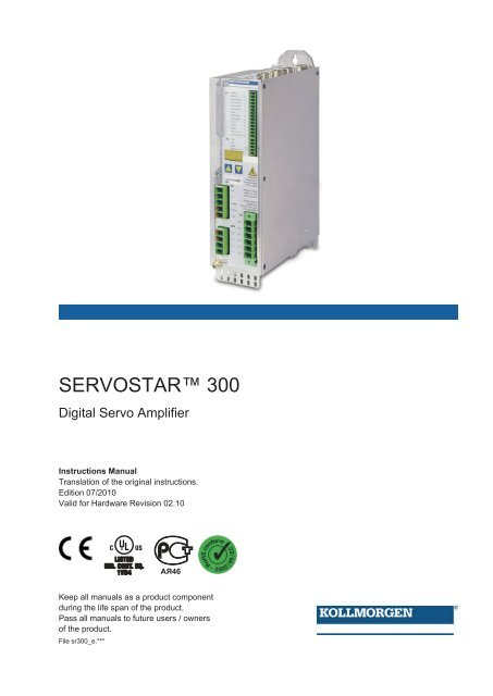
SERVOSTAR <strong>300</strong><br />
Digital Servo Amplifier<br />
Instructions Manual<br />
Translation of the original instructions.<br />
Edition 07/2010<br />
Valid for Hardware Revision 02.10<br />
Keep all manuals as a product component<br />
during the life span of the product.<br />
Pass all manuals to future users / owners<br />
of the product.<br />
File sr<strong>300</strong>_e.***
Record of Document Revisions:<br />
Revision Remarks<br />
06/2004 First edition<br />
04/2005 Restart lock -AS-, UL-listing, new pinning for X8, several corrections<br />
04/2005a order numbers 400V types for NA updated<br />
Chapter 1 updated, ComCoder wiring corrected, Acuro(BISS)-Interface new, max. station ad-<br />
11/2005 dress changed to 127, motor choke changed, SynqNet and EtherCAT expansion cards added,<br />
chapter 6 restructured, order codes restructured<br />
12/2005 Feedback section, termination resistors X1/X5, CE section<br />
02/2006<br />
Error messages and warnings updated, additional information (SERCOS), AWG cross-sections<br />
added, inch dimensions added, analog-in circuit updated, cross section (awg)<br />
05/2006<br />
CAN baud rate coding updated, LED display structure updated, input analog-in updated, BISS<br />
interface updated, hardware revision added, Errors/Warnings updated<br />
09/2006 New document structure, new cover design, warning n24, Quickstart integrated<br />
New part number scheme, termination resistors CAN interface and X5 corrected, branding upda-<br />
03/2007<br />
ted, chapter leakance current new, chapter "servo system graphics" expanded and moved,<br />
chapter "various mains supply networks" moved, trouble shooting reduced, Feedback expanded<br />
and restructured, enc emulation, DC-Link expanded, AS restructured, accessories removed<br />
07/2007 Timing diagramm motor brake, standards updated (EMC and LVD)<br />
10/2007 Target group, use as directed, standards<br />
05/2008<br />
Safety symbols acc. to ANSI Z535.6, repair, deinstallation, dU/dt info, syntax: "regen" => "brake",<br />
techn. data connectors, cable requirements, data brake circuit<br />
06/2008 EC Declaration new, Hiperface corrected, option FAN new<br />
10/2008 SCCR -> 42kA<br />
02/2009 Product brand, single phase operation, repair/disposal request form<br />
05/2010<br />
SSI input clock signal inverted, Gost-R, CE, option FAN, AS->STO, Emergency Stop examples<br />
moved to WIKI<br />
07/2010 Wiki links updated<br />
Hardware Revision (HR) History<br />
Hardware Revision<br />
usable<br />
Firmware Revision<br />
usable<br />
DRIVEGUI.EXE Revision Remarks<br />
02.01 � 2.18 � 1.30 Build 0056 Start HWR<br />
02.10 � 3.75 � 2.00 Build 0074 AS->STO, new approval<br />
WINDOWS is a registered trademark of Microsoft Corp.<br />
HIPERFACE is a registered trademark of Max Stegmann GmbH<br />
EnDat is a registered trademark of Dr. Johannes Heidenhain GmbH<br />
EtherCAT is a registered trademark of EtherCAT Technology Group<br />
SERVOSTAR is a registered trademark of Kollmorgen Corporation<br />
Technical changes which improve the performance of the device may be made without prior notice!<br />
Printed in the Federal Republic of Germany<br />
All rights reserved. No part of this work may be reproduced in any form (by photocopying, microfilm or any<br />
other method) or stored, processed, copied or distributed by electronic means without the written permission<br />
of Danaher Motion GmbH.
Kollmorgen 07/2010 Contents<br />
page<br />
1 General<br />
1.1 About this manual. ...............................................................7<br />
1.2 Target group ....................................................................7<br />
1.3 Hints for the online edition (PDF format) ..............................................7<br />
1.4 Abbreviations used ...............................................................8<br />
1.5 Symboles used ..................................................................9<br />
1.6 Standards used. .................................................................9<br />
2 Safety<br />
2.1 Safety Instructions ..............................................................10<br />
2.2 Use as directed. ................................................................11<br />
2.3 Prohibited use. .................................................................11<br />
3 Approvals<br />
3.1 Conformance with UL and cUL ....................................................12<br />
3.2 EC Conformance ...............................................................13<br />
3.2.1 European Directives and Standards for the machine builder .........................13<br />
3.2.2 EC Declaration of Conformity .................................................14<br />
3.3 GOST-R Conformance ...........................................................15<br />
4 Handling<br />
4.1 Transport .....................................................................17<br />
4.2 Packaging .....................................................................17<br />
4.3 Storage .......................................................................17<br />
4.4 Maintenance, Cleaning. ..........................................................17<br />
4.5 Disassembling .................................................................18<br />
4.6 Repair ........................................................................18<br />
4.7 Disposal ......................................................................18<br />
5 Package<br />
5.1 Package supplied ...............................................................19<br />
5.2 Nameplate ....................................................................19<br />
5.3 Part number scheme ............................................................20<br />
6 Technical description<br />
6.1 The SERVOSTAR <strong>300</strong> family of digital servo amplifiers .................................21<br />
6.2 Technical data .................................................................23<br />
6.2.1 Technical data for 110/230 V (types S3_ _6_) ....................................23<br />
6.2.2 Technical data for 400/480 V (types S3_ _0_) ....................................24<br />
6.2.3 Inputs / outputs ............................................................25<br />
6.2.4 Connectors ...............................................................25<br />
6.2.5 Recommended tightening torques .............................................25<br />
6.2.6 Fusing ...................................................................25<br />
6.2.7 Ambient conditions, ventilation, mounting position .................................26<br />
6.2.8 Conductor cross-sections ....................................................26<br />
6.3 Motor holding brake .............................................................27<br />
6.4 LED display. ...................................................................28<br />
6.5 Grounding system ..............................................................28<br />
6.6 Dynamic braking (brake circuit) ....................................................28<br />
6.7 Switch-on and switch-off behavior ..................................................30<br />
6.7.1 Behavior in standard operation ................................................31<br />
6.7.2 Behavior in the event of an error (with standard setting) ............................32<br />
6.8 Stop- / Emergency Stop- Function to IEC 60204 .......................................33<br />
6.8.1 Stop: Standards. ...........................................................33<br />
6.8.2 Emergency Stop: Standards ..................................................34<br />
6.9 Safety function STO .............................................................35<br />
6.9.1 Safety characteristic data ....................................................35<br />
6.9.2 Safety instructions ..........................................................36<br />
6.9.3 Use as directed ............................................................36<br />
6.9.4 Prohibited Use. ............................................................36<br />
6.9.5 Technical data and pinning ...................................................37<br />
6.9.6 Enlosure .................................................................37<br />
6.9.7 Wiring ...................................................................37<br />
SERVOSTAR <strong>300</strong> Instructions Manual 3
Contents 07/2010 Kollmorgen<br />
page<br />
6.9.8 Functional description .......................................................38<br />
6.9.8.1 Signal diagram (sequence) ................................................39<br />
6.9.8.2 Control circuit ..........................................................40<br />
6.9.8.3 Functional test. .........................................................41<br />
6.9.8.4 Mains supply circuit. .....................................................41<br />
6.10 Shock-hazard protection. .........................................................42<br />
6.10.1 Leakage current ...........................................................42<br />
6.10.2 Residual current protective device (RCD). .......................................42<br />
6.10.3 Isolating transformers .......................................................42<br />
7 Mechanical Installation<br />
7.1 Safety Instructions ..............................................................43<br />
7.2 Guide to mechanical installation. ...................................................43<br />
7.3 Assembly .....................................................................44<br />
7.4 Dimensions ....................................................................45<br />
8 Electrical installation<br />
8.1 Safety Instructions ..............................................................47<br />
8.2 Guide to electrical installation. .....................................................48<br />
8.3 Wiring ........................................................................49<br />
8.3.1 Safety instructions ..........................................................49<br />
8.3.2 Shielding connection to the front panel. .........................................50<br />
8.3.3 Technical data for connecting cables ...........................................51<br />
8.4 Components of a servo system ....................................................52<br />
8.5 Block diagram. .................................................................53<br />
8.6 Connector assignments ..........................................................54<br />
8.7 Connection diagram (Overview). ...................................................55<br />
8.8 Electrical supply ................................................................56<br />
8.8.1 Connection to various mains supply networks ....................................56<br />
8.8.2 24V auxiliary supply (X4). ....................................................57<br />
8.8.3 Mains supply connection (X0), three phase ......................................57<br />
8.8.4 Mains supply connection (X0), two phase without neutral ...........................57<br />
8.8.5 Mains supply connection (X0), single phase with neutral ............................58<br />
8.9 External brake resistor (X8) .......................................................59<br />
8.10 DC bus link (X8) ................................................................59<br />
8.11 Motor connection with brake (X9). ..................................................60<br />
8.12 Feedback .....................................................................61<br />
8.12.1 Resolver (X2) .............................................................62<br />
8.12.2 Sine Encoder with BISS (X1) .................................................63<br />
8.12.3 Sine Encoder with EnDat 2.1 .................................................64<br />
8.12.4 Sine Encoder with HIPERFACE (X1) ...........................................65<br />
8.12.5 Sine Encoder without data channel (X1). ........................................66<br />
8.12.6 Sine Encoder with Hall (X1) ..................................................67<br />
8.12.7 ROD (AquadB) 5V (X1) ......................................................68<br />
8.12.8 ROD (AquadB) 5V with Hall (X1) ..............................................69<br />
8.12.9 ROD (AquadB) 5V (X5) ......................................................70<br />
8.12.10 ROD (AquadB) 5V with Hall (X5/X1). ...........................................71<br />
8.12.11 ROD (AquadB) 24V (X3). ....................................................72<br />
8.12.12 ROD (AquadB) 24V with Hall (X3/X1). ..........................................73<br />
8.12.13 SSI Encoder (X5) ..........................................................74<br />
8.12.14 Hall sensors (X1). ..........................................................75<br />
8.13 Electronic Gearing, Master-slave operation ...........................................76<br />
8.13.1 Connection to an incremental encoder (AquadB) master, 5 V (X5) ....................76<br />
8.13.2 Connection to stepper motor controllers (step and direction) .........................77<br />
8.13.2.1 Step/Direction with 5 V signal level (X5) ......................................77<br />
8.13.2.2 Step/Direction with 24 V signal level (X3) .....................................77<br />
8.14 Encoder emulation ..............................................................78<br />
8.14.1 Incremental encoder output - A quad B (X5) .....................................78<br />
8.14.2 SSI encoder output (X5) .....................................................79<br />
8.15 Digital and analog inputs and outputs ...............................................80<br />
8.15.1 Analog inputs (X3). .........................................................80<br />
8.15.2 Digital inputs (X3/X4). .......................................................81<br />
8.15.3 Digital outputs (X3) .........................................................82<br />
8.16 RS232 interface, PC connection (X6) ...............................................83<br />
8.17 CANopen interface (X6) ..........................................................84<br />
4 SERVOSTAR <strong>300</strong> Instructions Manual
Kollmorgen 07/2010 Contents<br />
page<br />
9 Setup<br />
9.1 Safety Instructions ..............................................................85<br />
9.2 Setup software .................................................................86<br />
9.2.1 General ..................................................................86<br />
9.2.1.1 Use as directed .........................................................86<br />
9.2.1.2 Software description .....................................................86<br />
9.2.1.3 Hardware requirements. ..................................................87<br />
9.2.1.4 Operating systems ......................................................87<br />
9.2.2 Installation under WINDOWS .................................................87<br />
9.3 Quickstart .....................................................................88<br />
9.3.1 Preparation ...............................................................88<br />
9.3.1.1 Unpacking, Mounting and Wiring the Servo Amplifier ...........................88<br />
9.3.1.2 Documents ............................................................88<br />
9.3.1.3 Minimum Wiring for Drive Test .............................................89<br />
9.3.2 Connect ..................................................................90<br />
9.3.3 Important Screen Elements. ..................................................91<br />
9.3.4 Setup Wizard. .............................................................92<br />
9.3.4.1 Basic Setup ............................................................92<br />
9.3.4.2 Units/Mechanical. .......................................................93<br />
9.3.4.3 Motor (rotary) / Feedback .................................................94<br />
9.3.4.4 Motor (linear) / Feedback (Encoder) .........................................94<br />
9.3.4.5 Save Parameters and Restart. .............................................95<br />
9.3.5 Motion Service (Jog Mode) ...................................................95<br />
9.3.6 More Setup Screens ........................................................96<br />
9.4 Multi-axis system ...............................................................97<br />
9.4.1 Station address for CAN-bus .................................................97<br />
9.4.2 Baud rate for CAN-bus ......................................................97<br />
9.5 Keypad operation / LED display ....................................................97<br />
9.5.1 Keypad operation ..........................................................98<br />
9.5.2 Status display .............................................................98<br />
9.5.3 Standard menu ............................................................98<br />
9.5.4 Advanced menu ...........................................................99<br />
9.6 Error messages ...............................................................100<br />
9.7 Warning messages. ............................................................101<br />
9.8 Trouble Shooting ..............................................................102<br />
10 Expansions Cards<br />
10.1 Guide to installation of expansion cards. ............................................103<br />
10.2 Expansion card -I/O-14/08- ......................................................104<br />
10.2.1 Technical data ............................................................104<br />
10.2.2 LEDs ...................................................................104<br />
10.2.3 Entering a motion block number (example) .....................................104<br />
10.2.4 Connector assignments ....................................................105<br />
10.2.5 Connection diagram (default) ................................................106<br />
10.3 Expansion card -PROFIBUS-. ....................................................107<br />
10.3.1 Connection technology .....................................................107<br />
10.3.2 Connection diagram .......................................................107<br />
10.4 Expansion card -SERCOS- ......................................................108<br />
10.4.1 LEDs ...................................................................108<br />
10.4.2 Connection technology .....................................................108<br />
10.4.3 Connection diagram .......................................................109<br />
10.4.4 Modifying the station address ................................................109<br />
10.4.5 Modifying the baud rate and optical power ......................................109<br />
10.5 Expansion card -DEVICENET-. ...................................................110<br />
10.5.1 Connection technology .....................................................110<br />
10.5.2 Connection diagram .......................................................110<br />
10.5.3 Combined module/network status-LED ........................................111<br />
10.5.4 Setting the station address (device address) ....................................111<br />
10.5.5 Setting the transmission speed ...............................................111<br />
10.5.6 Bus cable. ...............................................................112<br />
SERVOSTAR <strong>300</strong> Instructions Manual 5
Contents 07/2010 Kollmorgen<br />
page<br />
10.6 Expansion card -EtherCAT- ......................................................113<br />
10.6.1 LEDs ...................................................................113<br />
10.6.2 Connection diagram .......................................................113<br />
10.7 Expansion card -SYNQNET- .....................................................114<br />
10.7.1 NODE ID Switch ..........................................................114<br />
10.7.2 Node LED table ..........................................................114<br />
10.7.3 SynqNet Connection, Connector X21B/C (RJ-45) ................................114<br />
10.7.4 Digital inputs/outputs, connector X21A (SubD 15-pin, socket) .......................115<br />
10.7.5 Connection diagram digital inputs/outputs, connector X21A ........................115<br />
10.8 Expansion module -2CAN- .......................................................116<br />
10.8.1 Installation ...............................................................116<br />
10.8.2 Connection technology .....................................................116<br />
10.8.3 Connector assignments ....................................................117<br />
10.8.4 Connection diagram .......................................................117<br />
10.9 Option "FAN", ventilator control ...................................................118<br />
11 Appendix<br />
11.1 Glossary .....................................................................119<br />
11.2 Order codes ..................................................................121<br />
11.2.1 Servo amplifiers. ..........................................................121<br />
11.2.2 Expansion cards ..........................................................121<br />
11.2.3 Mating connectors .........................................................121<br />
11.3 Repair-/Disposal request Telefax form. .............................................122<br />
11.4 Index ........................................................................123<br />
6 SERVOSTAR <strong>300</strong> Instructions Manual
Kollmorgen 07/2010 General<br />
1 General<br />
1.1 About this manual<br />
1.2 Target group<br />
This manual describes the SERVOSTAR <strong>300</strong> (S<strong>300</strong>) series of digital servo amplifiers<br />
(S<strong>300</strong>, standard version, 1.5A ...10A rated current).<br />
A more detailed description of the expansion cards that are currently available and the<br />
digital connection to automation systems can be found, together with our applications<br />
notes, in Acrobat-Reader format on the accompanying CD-ROM (system requirements:<br />
WINDOWS, Internet Browser, Acrobat Reader) in different languages.<br />
Technical data and dimensional drawings of accessories such as cables, brake resistors,<br />
mains supplies, etc., can be found in the accessories manual.<br />
This documentation can be printed out on any standard commercial printer. A printed<br />
copy of the documentation is available from us at extra cost.<br />
More background information can be found in the "Product WIKI", please check<br />
www.wiki-kollmorgen.eu.<br />
This manual addresses personnel with the following qualifications:<br />
Transport : only by personnel with knowledge of handling electrostatically sensitive<br />
components.<br />
Unpacking: only by electrically qualified personnel.<br />
Installation : only by electrically qualified personnel.<br />
Setup : only by qualified personnel with extensive knowledge of electrical<br />
engineering and drive technology<br />
The qualified personnel must know and observe the following standards:<br />
IEC 60364 and IEC 60664<br />
national accident prevention regulations<br />
During operation there are deadly hazards, with the possibility of death, severe<br />
injury or material damage. The operator must ensure that the safety instructions in<br />
this manual are followed. The operator must ensure that all personnel responsible<br />
for working with the servo amplifier have read and understood the Instructions<br />
Manual.<br />
1.3 Hints for the online edition (PDF format)<br />
Bookmarks:<br />
Table of contents and index are active bookmarks.<br />
Table of contents and index in the text:<br />
The lines are active cross references. Click on the desired line and the appropriate page<br />
is accessed.<br />
Page/chapter numbers in the text:<br />
Page/chapter numbers with cross references are active. Click at the page/chapter number<br />
to reach the indicated target.<br />
SERVOSTAR <strong>300</strong> Instructions Manual 7
General 07/2010 Kollmorgen<br />
1.4 Abbreviations used<br />
Abbrev. Meaning<br />
AGND Analog ground<br />
BTB/RTO Ready to operate<br />
CAN Fieldbus (CANopen)<br />
CE Communité Europeenne<br />
CLK Clock signal<br />
COM Serial interface for a PC-AT<br />
DGND Digital ground (for 24V and digital I/O)<br />
DIN German Institute for Industrial Standards<br />
Disk Magnetic storage (diskette, hard disk)<br />
EEPROM Electrically erasable programmable memory<br />
EMC Electromagnetic compatibility<br />
EMI Electromagnetic interference<br />
EN European Standard<br />
ESD Electrostatic discharge<br />
F-SMA Fiber Optic Cable connector according to IEC 60874-2<br />
IEC International Electrotechnical Commission<br />
IGBT Insulated-gate bipolar transistor<br />
INC Incremental interface<br />
ISO International Organization for Standardization<br />
LED Light-emitting diode<br />
MB Megabyte<br />
NI Zero pulse<br />
PC Personal computer<br />
PELV Protected low voltage<br />
PLC Programmable logic controller<br />
PWM Pulse-width modulation<br />
RAM Volatile memory<br />
RBallast / RBR Ballast resistor (= brake resistor or regen resistor)<br />
RBext External brake resistor<br />
RBint Internal brake resistor<br />
RES Resolver<br />
ROD digital encoder<br />
S1 continuous operation<br />
S3 Intermittent operation<br />
SRAM Static RAM<br />
SSI Synchronous serial interface<br />
STO Safe torque off, restart lock<br />
UL Underwriters Laboratories<br />
V AC Alternating voltage<br />
V DC DC voltage<br />
VDE Society of German Electrical Technicians<br />
8 SERVOSTAR <strong>300</strong> Instructions Manual
Kollmorgen 07/2010 General<br />
1.5 Symboles used<br />
Symbol Indication<br />
Indicates a hazardous situation which, if not avoided, will result in<br />
death or serious injury.<br />
Indicates a hazardous situation which, if not avoided, could result<br />
in death or serious injury.<br />
Indicates a hazardous situation which, if not avoided, could result<br />
in minor or moderate injury.<br />
Indicates situations which, if not avoided, could result in property<br />
damage.<br />
This is not a safety symbol.<br />
This symbol indicates important notes.<br />
1.6 Standards used<br />
Standard Content<br />
ISO 4762 Hexagon socket head cap screws<br />
ISO 11898 Road vehicles — Controller area network (CAN)<br />
ISO 13849 Safety of machinery: Safety-related parts of control systems<br />
ISO 12100 Safety of machinery: Basic concepts, general principles for design<br />
IEC 60085 Electrical insulation - Thermal evaluation and designation Maintenance<br />
IEC 60204 Safety of Machinery: Electrical equipment of machinery<br />
IEC 60364 Low-voltage electrical installations<br />
IEC 60439 Low-Voltage Switchgear and Controlgear Assemblies<br />
IEC 60664 Insulation coordination for equipment within low-voltage systems<br />
IEC 60721 Classification of environmental conditions<br />
IEC 61000 Electromagnetic compatibility (EMC)<br />
IEC 61131 Programmable controllers<br />
IEC 61491<br />
Electrical equipment of industrial machines – Serial data link for<br />
real-time communications between controls and drives.<br />
IEC 61508<br />
Functional safety of electrical/electronic/programmable electronic<br />
safety-related systems<br />
IEC 61800 Adjustable speed electrical power drive systems<br />
IEC 62061<br />
Functional safety of electrical/electronic/programmable electronic<br />
safety-related systems<br />
IEC 62079 Preparation of instructions - Structuring, content and presentation<br />
ANSI Z535 Product safety (symbols, colors, information)<br />
UL 840<br />
UL Standard for Safety for Insulation Coordination Including Clearances<br />
and Creepage Distances for Electrical Equipment<br />
UL 508C UL Standard for Safety Power Conversion Equipment<br />
ANSI American National Standard Institute, Inc.<br />
IEC International Electrotechnical Commission<br />
ISO International Organization for Standardization<br />
UL Underwriters Laboratories<br />
SERVOSTAR <strong>300</strong> Instructions Manual 9
Safety 07/2010 Kollmorgen<br />
2 Safety<br />
2.1 Safety Instructions<br />
During operation there are deadly hazards, with the possibility of death, severe<br />
injury or material damage. Do not open or touch the equipment during operation.<br />
Keep all covers and cabinet doors closed during operation. Touching the<br />
equipment is allowed during installation and commissioning for properly qualified<br />
persons only.<br />
— During operation, servo amplifiers may have uncovered live components,<br />
depending on their level of enclosure protection.<br />
— Control and power connections may be live, even though the motor is not<br />
rotating.<br />
— Servo amplifiers may have hot surfaces during operation.<br />
Surface can reach temperatures above 80°C.<br />
There is a danger of electrical arcing with damage to contacts and personal injury.<br />
Never undo any electrical connections to the servo amplifier while it is live.<br />
Wait at least five minutes after disconnecting the servo amplifier from the main<br />
supply power before touching potentially live sections of the equipment (e.g.<br />
contacts) or undoing any connections.<br />
Capacitors can still have dangerous voltages present up to five minutes after<br />
switching off the supply power. To be sure, measure the voltage in the DC Bus link<br />
and wait until it has fallen below 40V.<br />
Incorrect handling of the servo amplifier can lead to personal injury or material<br />
damage. Read this documentation before carrying out the installation and<br />
commissioning. It is vital that you keep to the technical data and information on<br />
connection requirements (nameplate and documentation).<br />
Only properly qualified personnel are permitted to carry out activities such as<br />
transport, installation, commissioning and maintenance. Properly qualified persons<br />
are those who are familiar with the transport, assembly, installation,<br />
commissioning and operation of the product, and who have the appropriate<br />
qualifications for their job. The qualified personnel must know and observe the<br />
following standards:<br />
— IEC 60364 and IEC 60664<br />
— national accident prevention regulations<br />
The manufacturer of the machine must produce a hazard analysis for the machine<br />
and take appropriate measures to ensure that unforeseen movements do not result<br />
in personal injury or material damage.<br />
Check the Hardware Revision Number of the product (see product label). This<br />
revision number must match the Hardware Revision Number on the cover page of<br />
the manual.<br />
The servo amplifiers contain electrostatically sensitive components which may be<br />
damaged by incorrect handling. Discharge your body before touching the servo<br />
amplifier. Avoid contact with highly insulating materials (artificial fabrics, plastic<br />
film etc.). Place the servo amplifier on a conductive surface.<br />
10 SERVOSTAR <strong>300</strong> Instructions Manual
Kollmorgen 07/2010 Safety<br />
2.2 Use as directed<br />
Servo amplifiers are safety components that are built into electrical plant or machines,<br />
and can only be operated as integral components of such plant or machines.<br />
The manufacturer of the machine must generate a hazard analysis for the machine, and<br />
take appropriate measures to ensure that unforeseen movements cannot cause injury or<br />
damage to any person or property.<br />
If the servo amplifiers are used in residential areas, in business/commercial areas, or in<br />
small industrial operations, then additional filter measures must be implemented by the<br />
user.<br />
Cabinet and Wiring<br />
The servo amplifiers must only be operated in a closed control cabinet, taking into<br />
account the ambient conditions defined on page 26. Ventilation or cooling may be necessary<br />
to keep the temperature within the cabinet below 40°C.<br />
Use only copper conductors for wiring. The conductor cross-sections can be derived from<br />
the standard IEC 60204 (alternatively for AWG cross-sections: NEC Table 310-16, 60°C<br />
or 75°C column).<br />
Power supply<br />
Servo amplifiers in the SERVOSTAR <strong>300</strong> series (overvoltage category III acc. to EN<br />
61800-5-1) can be supplied from 3-phase grounded (earthed) industrial supply networks<br />
(TN-system, TT-system with grounded neutral point, no more than 42kA symmetrical<br />
rated current at 110-10%...230V +10% or 208-10%...480V +10% depending on the amplifier<br />
type). Connection to other types of supply networks (with an additional isolating transformer)<br />
is described on page 56.<br />
Periodic overvoltage between phases (L1, L2, L3) and the housing of the servo amplifier<br />
must not exceed 1000V crest. In accordance with IEC 61800, voltage spikes (< 50µs)<br />
between phases must not exceed 1000V. Voltage spikes (< 50µs) between a phase and<br />
the housing must not exceed 2000V.<br />
Motors<br />
The SERVOSTAR <strong>300</strong> family of servo amplifiers is exclusively intended for driving suitable<br />
brush less synchronous servomotors or asynchronous motors with control of torque,<br />
speed and/or position.<br />
The rated voltage of the motors must be at least as high as the DC bus link voltage divided<br />
by 2 produced by the servo amplifier (UnMotor� UDC/ 2).<br />
Safety<br />
Observe the chapter "use as directed" on page 36 when you use the safety function STO.<br />
SERVOSTAR <strong>300</strong> Instructions Manual 11
Safety 07/2010 Kollmorgen<br />
2.3 Prohibited use<br />
Other use than described in chapter 2.2 is not intended and can lead to damage of persons,<br />
equipment or things.<br />
The use of the servo amplifier in the following environments is prohibited:<br />
- potentially explosive areas<br />
- environments with corrosive and/or electrically conductive acids, alkaline solutions,<br />
oils, vapors, dusts<br />
- directly on non-grounded supply networks or on asymmetrically grounded supplies<br />
with a voltage >230V.<br />
- on ships or off-shore applications<br />
Commissioning the servo amplifier is prohibited if the machine in which it was installed,<br />
- does not meet the requirements of the EC Machinery Directive<br />
- does not comply with the EMC Directive or with the Low Voltage Directive<br />
- does not comply with any national directives<br />
The control of holding brakes by the SERVOSTAR <strong>300</strong> alone may not be used in applications,<br />
where personnel security is to be ensured with the brake.<br />
12 SERVOSTAR <strong>300</strong> Instructions Manual
Kollmorgen 07/2010 Approvals<br />
3 Approvals<br />
3.1 Conformance with UL and cUL<br />
This servo amplifier is listed under UL file number E217428.<br />
UL (cUL)-certified servo amplifiers (Underwriters Laboratories Inc.) fulfil the relevant U.S.<br />
and Canadian standard (in this case UL 840 and UL 508C).<br />
This standard describes the fulfillment by design of minimum requirements for electrically<br />
operated power conversion equipment, such as frequency converters and servo amplifiers,<br />
which is intended to eliminate the risk of fire, electric shock, or injury to persons,<br />
being caused by such equipment. The technical conformance with the U.S. and Canadian<br />
standard is determined by an independent UL (cUL) inspector through the type testing<br />
and regular checkups.<br />
Apart from the notes on installation and safety in the documentation, the customer does<br />
not have to observe any other points in direct connection with the UL (cUL)-certification of<br />
the equipment.<br />
UL 508C<br />
UL 508C describes the fulfillment by design of minimum requirements for electrically operated<br />
power conversion equipment, such as frequency converters and servo amplifiers,<br />
which is intended to eliminate the risk of fire being caused by such equipment.<br />
UL 840<br />
UL 840 describes the fulfillment by design of air and insulation creepage spacings for<br />
electrical equipment and printed circuit boards.<br />
UL Markings<br />
� Use 60/75°C copper wire only for every model of this section.<br />
� Tightening torque for field wiring terminals see page 25<br />
� Use in a pollution degree 2 environment.<br />
� Use Class 1 wire only or equivalent.<br />
� Suitable for use on a circuit capable of delivering not more than 42kA rms symmetrical<br />
amperes for a max. voltage of 480 V.<br />
SERVOSTAR <strong>300</strong> Instructions Manual 13
Approvals 07/2010 Kollmorgen<br />
3.2 EC Conformance<br />
Conformance with the EC Machine Directive 2006/42/EC, the EC EMC Directive<br />
2004/108/EC and the Low Voltage Directive 2006/95/EC is mandatory for the supply of<br />
servo amplifiers within the European Community.<br />
The servo amplifier meets the noise immunity requirements to the 2nd environmental<br />
category (industrial environment). For noise emission the amplifier meets the requirement<br />
to a product of the category C2 (motor cable � 10m).<br />
This product can cause high-frequency interferences in non industrial<br />
environments which can require measures for interference suppression.<br />
With a motor cable length of 10m or longer, the servo amplifier meets the requirement to<br />
the category C3.<br />
The servo amplifiers have been tested by an authorized testing laboratory in a defined<br />
configuration, using the system components that are described in this documentation.<br />
Any divergence from the configuration and installation described in this documentation<br />
means that you will be responsible for carrying out new measurements to ensure conformance<br />
with regulatory requirements.<br />
3.2.1 European Directives and Standards for the machine builder<br />
Servo amplifiers are safety components that are intended to be incorporated into electrical<br />
plant and machines for industrial use. When the servo amplifiers are built into machines<br />
or plant, the amplifier must not be used until it has been established that the machine<br />
or equipment fulfills the requirements of the<br />
� EC Machinery Directive (2006/42/EC)<br />
� EC EMC Directive (2004/108/EC)<br />
� EC Low Voltage Directive (2006/95/EC)<br />
Standards to be applied for conformance with the EC Machinery Directive (2006/42/EC)<br />
EN 60204-1 (Safety and Electrical Equipment in Machines)<br />
EN 12100 (Safety of Machines)<br />
The manufacturer of the machine must generate a hazard analysis for the machine,<br />
and must implement appropriate measures to ensure that unforeseen movements<br />
cannot cause injury or damage to any person or property.<br />
The machine/plant manufacturer must check whether other standards or EC<br />
Directives must be applied to the machine/plant.<br />
Standards to be applied for conformance with the Low Voltage Directive (2006/95/EC):<br />
EN 60204-1 (Safety and Electrical Equipment in Machines)<br />
EN 60439-1 (Low-voltage switchgear and controlgear assemblies)<br />
Standards to be applied for conformance with the EMC Directive (2004/108/EC):<br />
EN 61000-6-1 / 2 (Interference Immunity in Residential & Industrial Areas)<br />
EN 61000-6-3 / 4 (Interference Generation in Residential & Industrial Areas)<br />
The manufacturer of the machine/plant is responsible for ensuring that it meets the limits<br />
required by the EMC regulations. Advice on the correct installation for EMC can be found<br />
in this documentation.<br />
We only guarantee the conformance of the servo system with the standards cited in this<br />
chapter if the components (motor, cables, chokes etc.) are those supplied by us.<br />
14 SERVOSTAR <strong>300</strong> Instructions Manual
Kollmorgen 07/2010 Approvals<br />
3.2.2 EC Declaration of Conformity<br />
SERVOSTAR <strong>300</strong> Instructions Manual 15
Approvals 07/2010 Kollmorgen<br />
3.3 GOST-R Conformance<br />
Certificate for servo amplifiers and accessories (cover page).<br />
16 SERVOSTAR <strong>300</strong> Instructions Manual
Kollmorgen 07/2010 Handling<br />
4 Handling<br />
4.1 Transport<br />
4.2 Packaging<br />
4.3 Storage<br />
� Transport by qualified personnel in the manufacturer’s original recyclable packaging<br />
� Avoid shocks while transporting<br />
� Transport temperature: -25 to +70°C, max. rate of change 20K / hour,<br />
class 2K3 acc. to EN61800-2<br />
� Transport humidity: max. 95% relative humidity, no condensation,<br />
class 2K3 acc. to EN61800-2<br />
� The servo amplifiers contain electrostatically sensitive components, that can<br />
be damaged by incorrect handling. Discharge yourself before touching the servo<br />
amplifier. Avoid contact with highly insulating materials, such as artificial<br />
fabrics and plastic films. Place the servo amplifier on a conductive surface.<br />
� If the packaging is damaged, check the unit for visible damage. In such an event, inform<br />
the shipper and the manufacturer.<br />
� Recyclable cardboard with inserts<br />
� Dimensions: (HxWxD) 115x365x275mm<br />
� Labeling: instrument label on outside of box<br />
� Storage only in the manufacturer’s original recyclable packaging<br />
� Max. stacking height 8 cartons<br />
� Storage temperature -25 to +55°C, max. rate of change 20K / hour,<br />
class 1K4 acc. to EN61800-2<br />
� Storage humidity 5 ... 95% relative humidity, no condensation,<br />
class 1K3 acc. to EN61800-2<br />
� Storage duration:<br />
Less than 1 year: without restriction.<br />
More than 1 year: capacitors must be re-formed before setting up and operating the<br />
servo amplifier. To do this, remove all electrical connections and apply single-phase<br />
230V AC for about 30 minutes to the terminals L1 / L2.<br />
4.4 Maintenance, Cleaning<br />
The instruments do not require any maintenance, opening the instruments invalidates the<br />
warranty.<br />
Cleaning : — if the casing is dirty: clean with Isopropanol or similar<br />
NOTICE: do not immerse or spray<br />
— Dirt inside the unit: must be cleaned by the manufacturer<br />
— For dirty protective grill on fan: clean with a dry brush<br />
SERVOSTAR <strong>300</strong> Instructions Manual 17
Handling 07/2010 Kollmorgen<br />
4.5 Disassembling<br />
4.6 Repair<br />
Observe the sequence below, if a servo amplifier has to be disassembled (e.g. for replacement).<br />
1. Electrical disconnection<br />
Switch off the main switch of the switchgear cabinet and the fuses that supply the<br />
system.<br />
Wait at least five minutes after disconnecting the servo amplifier from the main<br />
supply power before touching potentially live sections of the equipment (e.g.<br />
contacts) or undoing any connections. To be sure, measure the voltage in the DC<br />
Bus link and wait until it has fallen below 40V.<br />
Remove the connectors. Disconnect the earth (ground) connection at last.<br />
2. Check temperature<br />
During operation the heat sink of the servo amplifier may reach temperatures<br />
above 80°C (176°F). Before touching the device, check the temperature and wait<br />
until it has cooled down below 40°C (104°F).<br />
3. Disassembling<br />
4.7 Disposal<br />
Disassemble the servo amplifier (reverse of the procedure described in chapter "Mechanical<br />
installation).<br />
Repair of the servo amplifier must be done by the manufacturer. Opening the devices<br />
means loss of the guarantee. Use the telefax form on page 122 for repair request. You'll<br />
receive the current dispatch information.<br />
Disassemble the equipment as described in chapter 4.5 and send it in the original packaging<br />
to the address given in the dispatch information.<br />
In accordance to the WEEE-2002/96/EC-Guidelines we take old devices and accessories<br />
back for professional disposal. Transport costs are the responsibility of the sender. Use<br />
the telefax form on page 122 for disposal request. You'll receive the current dispatch<br />
information.<br />
Disassemble the equipment as described in chapter 4.5 and send it in the original packaging<br />
to the address given in the dispatch information.<br />
18 SERVOSTAR <strong>300</strong> Instructions Manual
Kollmorgen 07/2010 Package<br />
5 Package<br />
5.1 Package supplied<br />
5.2 Nameplate<br />
When an amplifier from the SERVOSTAR <strong>300</strong> series is ordered (order numbers �p.121),<br />
the following is supplied:<br />
— SERVOSTAR 3xx<br />
— Mating connectors X0, X3, X4, X8<br />
— Mating connector X9 only with SERVOSTAR 303-310 (S3xx6)<br />
— Instructions Manual<br />
— Online documentation on CD-ROM<br />
— Setup software DRIVEGUI.EXE on CD-ROM<br />
The mating SubD connectors are not part of the package!<br />
Accessories : (must be ordered separately, if required; description see accessories<br />
manual)<br />
— motor cable (prefabricated) with special shield clamp, or both power connectors<br />
separately, with the motor cable as a cut-off length<br />
— feedback cable (prefabricated)<br />
or both feedback connectors separately, with the feedback cable as a cut-off length<br />
— motor choke 3YL, for motor cables longer than 25 meters<br />
— external brake resistor BAR(U)<br />
— communication cable to the PC (� p.83) for setting parameters from a PC<br />
— power cable, control cables, fieldbus cables (as cut-off lengths)<br />
The nameplate depicted below is attached to the side of the servo amplifier.<br />
The information described below is printed in the individual fields.<br />
Servo amplifier type<br />
max. ambient<br />
temperature<br />
Serial number<br />
Electrical supply<br />
Installed load<br />
Comments<br />
Output current<br />
in S1 operation<br />
Enclosure Rating<br />
Hardware<br />
Revision<br />
SERVOSTAR <strong>300</strong> Instructions Manual 19
Package 07/2010 Kollmorgen<br />
5.3 Part number scheme<br />
Family<br />
S3 S<strong>300</strong><br />
Current rating<br />
01 1.5A rms<br />
03 3A rms<br />
06 6A rms<br />
10 10A rms<br />
Voltage rating<br />
0 208...480V<br />
6 110...230V<br />
* additional coding defines customer specific specials<br />
Comparison device name -> part number<br />
Device Name Part Number<br />
SERVOSTAR 303 S30361-NA<br />
SERVOSTAR 306 S30661-NA<br />
SERVOSTAR 310 S31061-NA<br />
SERVOSTAR 341 S30101-NA<br />
SERVOSTAR 343 S30301-NA<br />
SERVOSTAR 346 S30601-NA<br />
S30601-SE*<br />
Expansions<br />
NA no expansion,<br />
CANopen onboard<br />
FN controlled FAN<br />
DN DEVICENET<br />
PB PROFIBUS<br />
SE SERCOS<br />
EC EtherCAT<br />
SQ SYNQNET<br />
I/O I/O Extension<br />
Electr. options<br />
0 no option<br />
1 STO<br />
20 SERVOSTAR <strong>300</strong> Instructions Manual
Kollmorgen 07/2010 Technical description<br />
6 Technical description<br />
6.1 The SERVOSTAR <strong>300</strong> family of digital servo amplifiers<br />
Standard version<br />
� Two voltage classes with large nominal voltage range<br />
1 x 110V-10% ... 3 x 230V +10% (SERVOSTAR 303-310, S3xx6)<br />
3 x 208V-10% ... 3 x 480V + 10% (SERVOSTAR 341-346, S3xx0)<br />
� Overvoltage category III acc. to EN 61800-5-1<br />
� Shielding connection directly on the servo amplifier<br />
� Two analog inputs onboard<br />
� CANopen onboard (default: 500 kBaud), for integration in CAN-bus systems and for<br />
setting parameters for several drives via the PC interface of one of the amplifiers<br />
� Slot for an expansion card<br />
� RS232 and pulse direction interface onboard<br />
� Restart lock STO for personnel safety onboard, � p. 35<br />
� Intelligent position controller onboard<br />
� Multi feedback support<br />
� Synchronous servomotors, linear motors, asynchronous motors, high frequency<br />
spindles and DC motors can be used<br />
Power section<br />
� Directly on grounded 3-phase supply, 110V-10% or 230V-10% up to 480V +10%<br />
TN-network or TT-network with grounded neutral point, 42kA max. symmetrical current<br />
rating, connection to other supply types only via isolating transformer, �p.56<br />
� B6 bridge rectifier, integral supply filter and soft-start circuit<br />
� Single-phase supply operation possible (e.g. for setup)<br />
� Fusing (e.g. fusible cutout) to be provided by the user<br />
� Shielding All shielding connections are made directly on the amplifier<br />
� Output stage IGBT module with floating current measurement<br />
� Brake circuit with dynamic distribution of the regenerated power between<br />
several amplifiers on the same DC bus link circuit. Internal<br />
brake resistor as standard, external brake resistors if required.<br />
� DC bus link voltage 135 … 450 V DC or 260 … 900 V DC,<br />
can be connected in parallel.<br />
� Interference suppression filters are integrated for the electrical supply feed and the<br />
24V auxiliary supply voltage (with motor cable � 10m for C2 as per EN 61800-3, with<br />
motor cable > 10m for C3 as per EN 61800-3).<br />
Integrated safety<br />
� Appropriate insulation/creepage distances and electrical isolation ensure safe electrical<br />
separation, as per EN 61800-5-1, between the power input / motor connections<br />
and the signal electronics.<br />
� Soft-start, overvoltage detection, short-circuit protection, phase-failure monitoring.<br />
� Temperature monitoring of the servo amplifier and motor (if our motors and prefabricated<br />
cables are used).<br />
SERVOSTAR <strong>300</strong> Instructions Manual 21
Technical description 07/2010 Kollmorgen<br />
Auxiliary supply voltage 24V DC<br />
� Electrically isolated, internal fusing, from an external 24V DC power supply unit with,<br />
for instance, isolating transformer or uninterruptible power supply.<br />
Operation and parameter setting<br />
� With our user-friendly setup software, for setup via the serial interface of a PC.<br />
� If no PC is available: direct operation by two keys on the servo amplifier and a 3-character<br />
LED display.<br />
� Fully programmable via RS232 interface.<br />
Completely digital control<br />
� Digital current controller (space vector, pulse-width modulation, 62.5 µs)<br />
� Adjustable digital speed controller (62.5 µs)<br />
� Integrated position controller, with adaptation possibilities for all applications (250 µs)<br />
� Integrated step/direction interface for connecting a servomotor to a stepper controller<br />
� Evaluation of resolver signals and sine-cosine signals of high-resolution encoders<br />
� Encoder emulation (incremental, compatible with A quad B or SSI)<br />
Comfort functions<br />
� 2 programmable analog inputs<br />
� 4 programmable digital inputs<br />
� 2 programmable digital outputs<br />
� programmable logical combinations of digital signals<br />
Expansions<br />
� Option FAN, ventilator control, cannot be inserted later, � p.118<br />
� I/O-14/08 expansion card, � p.104<br />
� PROFIBUS DP expansion card, � p.107<br />
� SERCOS expansion card, � p.108<br />
� DeviceNet expansion card, � p.110<br />
� EtherCAT expansion card, � p. 113<br />
� SynqNet expansion card, � p. 114<br />
� -2CAN- expansion module, separated connectors for CAN-bus and RS232, � p.116<br />
� Several third-party expansion cards (ModBus, LightBus, FIP-IO etc. please contact<br />
the manufacturer for further information)<br />
22 SERVOSTAR <strong>300</strong> Instructions Manual
Kollmorgen 07/2010 Technical description<br />
6.2 Technical data<br />
6.2.1 Technical data for 110/230 V (types S3_ _6_)<br />
Electrical data DIM 303<br />
SERVOSTAR<br />
306 310<br />
Order Code — S30361 S30661 S31061<br />
Rated supply voltage<br />
(grounded supply, phase to phase)<br />
V~<br />
1 x 110V-10% … 1 x 230V +10%<br />
3 x 110V-10% … 3 x 230V +10%<br />
50/60 Hz<br />
Rated input power for S1 operation kVA 1.1 2.4 4<br />
Max. DC bus link voltage<br />
Rated output current (rms value, � 3%)<br />
V= 450<br />
at 1x115V (observe p. 58) Arms 3,5* 8* 10*<br />
at 1x230V (observe p. 58) Arms 3* 6* 10*<br />
at 3x115V Arms 3.5 8 10<br />
at 3x230V Arms 3 6 10<br />
Peak output current (current for approx. 5s, � 3%)<br />
at 1x115V (observe p. 58) Arms 9* 15* 20*<br />
at 1x230V (observe p. 58) Arms 9* 15* 20*<br />
at 3x115V Arms 9 15 20<br />
at 3x230V Arms 9 15 20<br />
Switching frequency of the output stage kHz 8<br />
at reduced current (50%) kHz 16<br />
Voltage rise speed dU/dt (see hints on page 60!)<br />
at 1x115V kV/µs 3,0<br />
at 1x230V kV/µs 3,3<br />
at 3x115V kV/µs 3,0<br />
at 3x230V kV/µs 3,3<br />
Technical data for brake circuit<br />
Threshold for overvoltage switch-off<br />
— � p.28<br />
at 115V VDC 235<br />
at 230V<br />
Motor inductance min.<br />
VDC 455<br />
at 1x115V mH 3.7 3.7 3.7<br />
at 1x230V mH 4.3 4.3 4.3<br />
at 3x115V mH 2.1 1.3 1.0<br />
at 3x230V mH 4.3 2.6 1.9<br />
Motor inductance max. mH Consult our customer support<br />
Form factor of the output current<br />
(rated conditions, min. load inductance)<br />
— 1.01<br />
Bandwidth of current controller kHz > 1.2<br />
Residual voltage drop at rated current V 4<br />
Thermal dissipation, output stage disabled W 12<br />
Thermal dissipation at rated current<br />
(incl. PSU losses, without brake dissipation)<br />
Mechanical data<br />
W 35 60 90<br />
Weight kg approx. 2.6<br />
Height, without connectors mm 275 279<br />
Width mm 70<br />
Depth, without connectors mm 171<br />
Depth, with connectors mm < 200<br />
* in single-phase applications nom./peak current is limited to value below nominal<br />
value dependent on the motor constant Kt and the motor speed (see p.58).<br />
SERVOSTAR <strong>300</strong> Instructions Manual 23
Technical description 07/2010 Kollmorgen<br />
6.2.2 Technical data for 400/480 V (types S3_ _0_)<br />
Electrical data DIM 341<br />
SERVOSTAR<br />
343 346<br />
Order Code — S30101 S30301 S30601<br />
Rated supply voltage<br />
(grounded supply, phase to phase)<br />
V~<br />
3 x 208V-10% … 480V +10% , 50/60<br />
Hz<br />
Rated input power for S1 operation kVA 1.2 2.5 5<br />
Max. DC bus link voltage<br />
Rated output current (rms value, ± 3%)<br />
V= 900<br />
at 3x208V Arms 2 5 6<br />
at 3x230V Arms 2 5 6<br />
at 3x400V Arms 1.5 4 6<br />
at 3x480V<br />
Peak output current (max. approx. 5s, ± 3%)<br />
Arms 1.5 3 6<br />
at 3x208V Arms 4.5 7.5 12<br />
at 3x230V Arms 4.5 7.5 12<br />
at 3x400V Arms 4.5 7.5 12<br />
at 3x480V Arms 4.5 7.5 12<br />
Switching frequency of the output stage kHz 8<br />
at reduced current (50%) kHz 16<br />
Voltage rise speed dU/dt (see hints on page 60!)<br />
at 3x208V kV/µs 3,0<br />
at 3x230V kV/µs 3,3<br />
at 3x400V kV/µs 5,7<br />
at 3x480V kV/µs 6,9<br />
Technical data for brake circuit<br />
Threshold for overvoltage switch-off<br />
— � p.28<br />
a 230V VDC 455<br />
a 400V VDC 800<br />
a 480V<br />
Motor inductance min.<br />
VDC 900<br />
at 3x208V mH 7.7 4.6 2.9<br />
at 3x230V mH 8.5 5.1 3.2<br />
at 3x400V mH 14.8 8.9 5.6<br />
at 3x480V mH 17.8 10.7 6.7<br />
Motor inductance max. mH Consult our customer support<br />
Form factor of the output current<br />
(rated conditions, min. load inductance)<br />
— 1.01<br />
Bandwidth of subordinate current controller kHz > 1.2<br />
Residual voltage drop at rated current V 5<br />
Thermal dissipation, output stage disabled W 12<br />
Thermal dissipation at rated current<br />
(incl. PSU losses, without brake dissipation)<br />
Mechanical data<br />
W 40 60 90<br />
Weight kg approx. 2.7<br />
Height, without connectors mm 275 278<br />
Width mm 70<br />
Depth, without connectors mm 171<br />
Depth, with connectors mm < 235<br />
24 SERVOSTAR <strong>300</strong> Instructions Manual
Kollmorgen 07/2010 Technical description<br />
6.2.3 Inputs / outputs, Auxiliary voltage<br />
6.2.4 Connectors<br />
Interface electr. data<br />
Analog inputs 1, 2 (resolution 14/12 bit) �10V<br />
Max. common-mode voltage �10V<br />
Digital control inputs as per IEC 61131-2 Type 1, max. 30VDC<br />
Digital control outputs, active high open Emitter, max. 30VDC, 10mA<br />
BTB/RTO output, relay contacts<br />
max. 30VDC, max 42VAC<br />
500mA<br />
Auxiliary supply voltage, electrically isolated,<br />
20V - 30V<br />
without motor brake/fan<br />
1A<br />
Auxiliary supply voltage, electrically<br />
24V (-0% +15%)<br />
isolated, with motor brake/fan<br />
2.5A (check voltage drop !)<br />
Min./max. output current to brake 0.15A / 1.5A<br />
Connector Type<br />
max.<br />
cross<br />
section *1<br />
permittedcur-<br />
rent * 2<br />
permittedtension<br />
*3<br />
Control signals X3, X4 Combicon connector 1,5mm² 4A 160V<br />
S303-310 Power signals X0,X8,X9 Combicon connector 2,5mm² 12A 630V<br />
S341-346 Power signals X0,X8,X9 Combicon connector 4mm² 16A 1000V<br />
Resolver input X2 SubD 9-pin (socket) 0,5mm² 1A
Technical description 07/2010 Kollmorgen<br />
6.2.7 Ambient conditions, ventilation, mounting position<br />
Storage hints � p.17<br />
Transport hints � p.17<br />
Supply voltage<br />
303-310*: 1x110V-10% …1x230V<br />
Auxiliary voltage<br />
without brake and fan<br />
with brake or fan<br />
+10% , 50/60 Hz<br />
3x110V-10% …3x230V +10% , 50/60 Hz<br />
341-346*: 3x208V-10% ...3x 480V +10% , 50/60 Hz<br />
20VDC...30VDC<br />
24 V DC (-0% +15%), check voltage drop !<br />
Ambient temperature in operation<br />
0...+40°C under rated conditions<br />
+40...+55°C with power derating 2.5% / °C<br />
Humidity in operation rel. humidity 85%, no condensation<br />
up to 1000 meters a.m.s.l. without restriction<br />
Site altitude<br />
1000…2500 meters a.m.s.l. with power derating<br />
1.5% / 100meters<br />
Pollution level Pollution level 2 as per IEC 60664-1<br />
Vibrations Class 3M2 according to IEC 60721-3-3<br />
Noise emission max. 45 dB(A)<br />
Enclosure protection IP 20<br />
Mounting position vertical � p.44<br />
Ventilation 1 A and 3 A types natural convection<br />
all other types built-on fan (optionally controlled, � p.118)<br />
Make sure that there is sufficient forced ventilation within the control cabinet.<br />
* order code reference see p. 20<br />
6.2.8 Conductor cross-sections<br />
Following IEC 60204, we recommend for single-axis systems:<br />
AC connection 1.5 mm² (14awg) 600V,80°C<br />
DC bus link<br />
Brake resistor<br />
1.5 mm² (14awg)<br />
1000V, 80°C,<br />
shielded for lengths<br />
>20cm<br />
Motor cables up to 25 m 1 - 1.5 mm² (14awg)<br />
600V, 80°C, shielded,<br />
capacitance
Kollmorgen 07/2010 Technical description<br />
6.3 Motor holding brake<br />
A 24V / max.1.5A holding brake in the motor can be controlled directly by the amplifier.<br />
This function does not ensure personnel safety! Hanging load (vertical axes)<br />
require an additional mechanical brake which must be safely operated.<br />
The brake only works with sufficient voltage level (� p.25). Check voltage drop,<br />
measure the voltage at brake input and check brake function (brake and no brake).<br />
The brake function must be enabled through the BRAKE setting (screen page: Motor). In<br />
the diagram below you can see the timing and functional relationships between the<br />
ENABLE signal, speed setpoint, speed and braking force. All values can be adjusted with<br />
parameters, the values in the diagram are default values.<br />
During the internal ENABLE delay time of 100ms (DECDIS), the speed setpoint of the<br />
servo amplifier is internally driven down an adjustable ramp to 0V. The output for the<br />
brake is switched on when the speed has reached 5 rpm (VELO), at the latest after 5 seconds<br />
(EMRGTO).<br />
The rise (fbrH) and fall (fbrL) times of the holding brake that is built into the motor are different<br />
for the various types of motor (see motor manual).<br />
A description of the interface can be found on page 60.<br />
SERVOSTAR <strong>300</strong> Instructions Manual 27
Technical description 07/2010 Kollmorgen<br />
6.4 LED display<br />
A 3-character LED display indicates the status of the amplifier after switching on the 24V<br />
supply (� p.99). When the keys on the front panel are used, the parameter and function<br />
numbers are shown, as well as the numbers for any errors that may occur (� p.100).<br />
6.5 Grounding system<br />
AGND — analog inputs, internal analog ground, encoder emulation, RS232, CAN<br />
DGND — digital inputs/outputs and the 24V supply, optically isolated.<br />
6.6 Dynamic braking (brake circuit)<br />
During dynamic braking with the aid of the motor, energy is fed back into the servo amplifier.<br />
This regenerative energy is dissipated as heat in the brake resistor. The brake resistor<br />
is switched in by the brake circuit.<br />
The setup software can be used to adapt the brake circuit (thresholds) according to the<br />
electrical supply voltage.<br />
Our customer service can help you with the calculation of the brake power that is necessary<br />
for your system. A simple method is described in the "Product Wiki" which is accessible<br />
at www.wiki-kollmorgen.eu.<br />
A description of the interface can be found on page 59.<br />
Functional description:<br />
1.- Individual amplifiers, not coupled through the DC bus link circuit (DC+, DC-)<br />
When the energy fed back from the motor has an average or peak power that exceeds<br />
the preset level for the brake power rating, then the servo amplifier generates the warning<br />
“n02 brake power exceeded” and the brake circuit is switched off.<br />
The next internal check of the DC bus link voltage (after a few milliseconds) detects an<br />
overvoltage and the output stage is switched off, with the error message “Overvoltage<br />
F02” (� p.100).<br />
The BTB/RTO contact (terminals X3/2,3) will be opened at the same time (�p.82)<br />
2.- Several servo amplifiers coupled through the DC bus link (DC+, DC-)<br />
Using the built-in brake circuit, several amplifiers (even with different current ratings) can<br />
be operated off a common DC bus link, without requiring any additional measures.<br />
The combined (peak and continuous) power of all amplifiers is always available. The<br />
switch-off on overvoltage takes place as described under 1. (above) for the amplifier that<br />
has the lowest switch-off threshold (resulting from tolerances).<br />
Technical data of the brake circuits dependent on the amplifiers type and the mains voltage<br />
situation see table on the next page.<br />
28 SERVOSTAR <strong>300</strong> Instructions Manual
Kollmorgen 07/2010 Technical description<br />
Technical Data:<br />
Brake circuit Supply voltage / V<br />
Type Rated data DIM 115 230 400 480<br />
Switch-on (upper) threshold of brake circuit V 200 400<br />
Overvoltage F02 V 235 455<br />
Internal brake resistor (RBint) Ohm 66 66<br />
Continuous power internal brake resistor (RBint)<br />
Max. brake power (average for 1s)<br />
W<br />
kW<br />
20<br />
0,4<br />
20<br />
0,35<br />
—<br />
Pulse brake power kW 0,84 3<br />
External brake resistor (RBext), optional Ohm 66 66<br />
Contuous brake power external (RBext) kW 0,3 0,3<br />
Switch-on (upper) threshold of brake circuit V 200 400<br />
Overvoltage F02 V 235 455<br />
Internal brake resistor (RBint) Ohm 66 66<br />
Continuous power internal brake resistor (RBint)<br />
Max. brake power (average for 1s)<br />
W<br />
kW<br />
50<br />
0,84<br />
50<br />
0,88<br />
—<br />
Pulse brake power kW 0,84 3<br />
External brake resistor (RBext), optional Ohm 66 66<br />
Contuous brake power external (RBext) kW 1 1<br />
Switch-on (upper) threshold of brake circuit V 400 720 840<br />
Overvoltage F02 V 455 800 900<br />
Internal brake resistor (RBint) Ohm 91 91 91<br />
Continuous power internal brake resistor (RBint)<br />
Max. brake power (average for 1s)<br />
W<br />
—<br />
20<br />
0,35<br />
20<br />
0,33<br />
20<br />
0,34<br />
Pulse brake power kW 2,1 7 9<br />
External brake resistor (RBext), optional Ohm 91 91 91<br />
Contuous brake power external (RBext) kW 0,3 0,3 0,3<br />
Switch-on (upper) threshold of brake circuit V 400 720 840<br />
Overvoltage F02 V 455 800 900<br />
Internal brake resistor (RBint) Ohm 91 91 91<br />
Continuous power internal brake resistor (RBint)<br />
Max. brake power (average for 1s)<br />
W<br />
—<br />
50<br />
0,91<br />
50<br />
0,86<br />
50<br />
0,85<br />
Pulse brake power kW 2,1 7 9<br />
External brake resistor (RBext), optional Ohm 91 91 91<br />
Contuous brake power external (RBext) kW 1,0 1,0 1,0<br />
303<br />
(S30361)<br />
306 / 310<br />
(S30661/S31061)<br />
341<br />
(S30101)<br />
343 / 346<br />
(S30301/S30601)<br />
Suitable external brake resistors can be found in our accessories manual.<br />
SERVOSTAR <strong>300</strong> Instructions Manual 29
Technical description 07/2010 Kollmorgen<br />
6.7 Switch-on and switch-off behavior<br />
This chapter describes the switch-on and switch-off behavior of the SERVOSTAR and the<br />
steps required to achieve operational stopping or emergency stop behavior that complies<br />
with standards.<br />
The servo amplifier’s 24 V supply must remain constant. The ASCII commands<br />
ACTFAULT (error response) and STOPMODE (ENABLE signal response) dictate<br />
how the drive will behave.<br />
ACTFAULT / Behavior (see also ASCII reference in the online help of the setup soft-<br />
STOPMODE ware)<br />
0 Motor coasts to a standstill in an uncontrolled manner<br />
1 (default) Motor is braked in a controlled manner<br />
Behavior during a power failure<br />
The servo amplifiers use an integrated circuit to detect if one or more input phases<br />
(power supply feed) fail. The behavior of the servo amplifier is set using the setup software:<br />
Under “Response to Loss of Input Phase” (PMODE) on the Basic Setup screen,<br />
select:<br />
� Warning if the higher-level control system is to bring the drive to a standstill: Warning<br />
n05 is output if an input phase is missing, and the motor current is limited to 4 A.<br />
The servo amplifier is not disabled. The higher-level control system can now selectively<br />
end the current cycle or start bringing the drive to a standstill. Therefore, the error<br />
message “MAINS BTB, F16" is output on a digital output of the servo amplifier<br />
and evaluated by the control system, for instance.<br />
� Error message if the servo amplifier is to bring the drive to a standstill: Error message<br />
F19 is output if an input phase is missing. The servo amplifier is disabled and the<br />
BTB contact opens. Where the factory setting is unchanged (ACTFAULT=1), the motor<br />
is braked using the set “EMERGENCY STOP RAMP”.<br />
Behavior when undervoltage threshold is reached<br />
If the undervoltage threshold is undershot in the DC bus link (the threshold value<br />
depends on the type of servo amplifier), the error message “UNDERVOLTAGE, F05" is<br />
displayed. The drive response depends on the ACTFAULT/STOPMODE setting.<br />
Behavior with enabled “holding brake” function<br />
Servo amplifiers with an enabled holding brake function have a special procedure for<br />
switching off the output stage ( � p. 27). Removing the ENABLE signal triggers electrical<br />
braking. As with all electronic circuits, the general rule applies that there is a possibility of<br />
the internal “holding brake” module failing. Bringing a motor to a standstill using a holding<br />
brake in a way that is personnel safe also requires an electromechanical “make” contact<br />
for the holding equipment and a suppressor device for the brake.<br />
Behavior of the safety function STO<br />
With the personnel safe, certified safety function STO, the drive can be secured on standstill<br />
using its internal electronics so that even when power is being supplied, the drive<br />
shaft is protected against unintentional restart. The chapter “Safety Function STO”<br />
describes how to use the STO function. See page 35 onwards.<br />
30 SERVOSTAR <strong>300</strong> Instructions Manual
Kollmorgen 07/2010 Technical description<br />
6.7.1 Behavior in standard operation<br />
The behavior of the servo amplifier always depends on the current setting of a number of<br />
different parameters (e.g., ACTFAULT, VBUSMIN, VELO, STOPMODE, etc.; see online<br />
help). The diagram below illustrates the correct functional sequence for switching the<br />
servo amplifier on and off.<br />
Devices which are equipped with a selected “Brake” function use a special sequence for<br />
switching off the output stage (� p.27).<br />
The safety function STO can be used to switch off the drive, so that personnel safety is<br />
ensured at the drive shaft (� p. 35).<br />
SERVOSTAR <strong>300</strong> Instructions Manual 31
Technical description 07/2010 Kollmorgen<br />
6.7.2 Behavior in the event of an error (with standard setting)<br />
The behavior of the servo amplifier always depends on the current setting of a number of<br />
different parameters (e.g., ACTFAULT, VBUSMIN, VELO, STOPMODE, etc.; see online<br />
help). The diagram shows the startup procedure and the procedure that the internal control<br />
system follows in the event of one or more electrical supply phases failing, assuming<br />
that the standard parameter settings apply.<br />
(F16/F19 = error messages Mains BTB /input phase, F05 = error message Undervoltage)<br />
Even if there is no intervention from an external control system (in the example, the<br />
ENABLE signal remains active), the motor is immediately braked using the emergency<br />
stop ramp if an input phase error is detected and assuming that no changes have been<br />
made to the factory setting (ACTFAULT=1).<br />
32 SERVOSTAR <strong>300</strong> Instructions Manual
Kollmorgen 07/2010 Technical description<br />
6.8 Stop- / Emergency Stop- Function to IEC 60204<br />
With the personnel safe, certified safety function STO (see page 35 onwards) the<br />
drive can be secured on standstill (torque-free) using its internal electronics so<br />
that even when power is being supplied, the drive shaft is protected against<br />
unintentional restart.<br />
The parameters “STOPMODE” and “ACTFAULT” must be set to 1 in order to<br />
implement the stop categories. If necessary, change the parameters via the<br />
terminal screen of the setup software and store the data in the EEPROM.<br />
Examples for implementation can be found in the Product WIKI on page "Stop and<br />
Emergency Stop Function".<br />
6.8.1 Stop: Standards<br />
The Stop function is used to shut down the machine in normal operation. The Stop functions<br />
are defined by IEC 60204.<br />
Category 0: Shut-down by immediate switching-off of the energy supply to the<br />
drive machinery (i.e. an uncontrolled shut-down);<br />
Category 1: A controlled shut-down , whereby the energy supply to the drive<br />
machinery is maintained to perform the shut-down, and the energy<br />
supply is only interrupted when the shut-down has been completed;<br />
Category 2: A controlled shut-down, whereby the energy supply to the drive<br />
machinery is maintained.<br />
The Stop Category must be determined by a risk evaluation of the machine. In addition,<br />
suitable means must be provided to guarantee a reliable shut-down.<br />
Category 0 and Category 1 Stops must be operable independently of the operating mode,<br />
whereby a Category 0 Stop must have priority. Stop functions must be implemented by<br />
disconnection of the appropriate circuitry, and have priority over assigned start functions.<br />
If necessary, provision must be made for the connection of protective devices and<br />
lock-outs. If applicable, the Stop function must signal its status to the control logic. A reset<br />
of the Stop function must not create a hazardous situation.<br />
Examples for implementation can be found in the Product WIKI on page "Stop and<br />
Emergency Stop Function".<br />
SERVOSTAR <strong>300</strong> Instructions Manual 33
Technical description 07/2010 Kollmorgen<br />
6.8.2 Emergency Stop: Standards<br />
The emergency Stop function is used for the fastest possible shut-down of the machine<br />
in a dangerous situation. The Emergency Stop function can be triggered by the actions of<br />
a single person. It must be fully functional and available at all times. The user must not<br />
have to work out how to operate this mechanism.<br />
The Emergency Stop function is defined by IEC 60204.<br />
In addition to the requirements for Stop, the emergency Stop must fulfil the following<br />
requirements:<br />
� emergency stop must have priority over all other functions and controls in all operating<br />
situations;<br />
� the energy supply to any drive machinery that could cause dangerous situations<br />
must be switched off as fast as possible, without causing any further hazards (e.g. by<br />
using mechanical latching devices that do not require an external supply of energy,<br />
by counter-current braking in Stop Category 1);<br />
� the reset must not initiate a restart.<br />
If necessary, provision must be made for the additional connection of emergency stop<br />
devices (see IEC 60204, "Requirements for emergency stop devices"). The Emergency<br />
Stop must be effective as a stop of either Category 0 or Category 1.<br />
The Emergency Stop Category must be determined by a risk evaluation of the machine.<br />
Category 0<br />
Only hard-wired, electromechanical components may be used for the Category 0 Emergency<br />
Stop function. It must not be triggered using switching logic (hardware or software),<br />
by transferring commands via a communication network, or via a data link.<br />
The drive must be shut down using an electromechanical circuit. If the connected servo<br />
motor has an integrated brake, this must always be controlled by an electromechanical<br />
circuit as well.<br />
Category 1<br />
With the Category 1 Emergency Stop function, there must be absolute certainty in terms<br />
of the power supply for the machine drives being switched off (i.e., secured) using electromechanical<br />
components. Additional Emergency Stop equipment may be connected.<br />
Bringing the motor to a standstill by interrupting the mains supply and using controlled<br />
electronic braking. The 24 V supply for the servo amplifier must remain constant. The<br />
issue of which circuit should be used is highly dependent on the requirements of the<br />
application at hand.<br />
In most servo motors a brake has only the function of a holding brake. To ensure an<br />
emergency stop function, the braking torque that is required must be checked. If the holding<br />
brake fulfills the dynamic requirements, it must be taken into acount that this application<br />
will cause increased wear.<br />
Examples for implementation can be found in the Product WIKI on page "Stop and<br />
Emergency Stop Function".<br />
34 SERVOSTAR <strong>300</strong> Instructions Manual
Kollmorgen 07/2010 Technical description<br />
6.9 Safety function STO<br />
A frequently required application task is the protection of personnel against the restarting<br />
of drives. The SERVOSTAR <strong>300</strong> servo amplifier offers, even in the basic version, a single<br />
channel STO function (Safe Torque Off) that can be used as a personnel safe restart<br />
lock.<br />
The safety function STO can be operated from a safe external control (semiconductor<br />
output or driven contact).<br />
The safetys concept is certified. The safety circuit concept for realizing the safety function<br />
"Safe Torque Off" in the servo amplifiers SERVOSTAR <strong>300</strong> is suited for SIL CL 2 according<br />
to IEC 62061 and PLd according to ISO 13849-1.<br />
Advantages of the restart lock STO :<br />
— the DC bus link remains charged up, since the mains supply line remains active<br />
— only low voltages are switched, so there is no contact wear<br />
— very little wiring is required<br />
6.9.1 Safety characteristic data<br />
The subsystems (servo amplifiers) are totally described for safety technics with the<br />
characteristic data SIL CL, PFHD and SFF.<br />
Device<br />
STO-Enable<br />
Operation<br />
mode<br />
STO single<br />
channel<br />
EN 13849-1 EN 62061<br />
PFHD<br />
[1/h]<br />
SFF<br />
[%]<br />
MTTFd<br />
[Year]<br />
PLd, Cat 3 SIL CL 2 0 100 311<br />
SERVOSTAR <strong>300</strong> Instructions Manual 35
Technical description 07/2010 Kollmorgen<br />
6.9.2 Safety instructions<br />
Drives with a suspended load must have an additional safe mechanical blocking<br />
(e.g. by a motor-holding brake). The amplifier cannot hold the load when STO is<br />
active. That could result in serious injury.<br />
When STO is engaged during operation by separating input STO-Enable from<br />
24VDC, the motor runs down out of control and the servo amplifier displays the<br />
error F27. There is no possibility of braking the drive controlled. If a controlled<br />
braking before the use of STO is necessary, the drive must be braked and the input<br />
STO-ENABLE has to be separated from +24 VDC time-delayed.<br />
If the safety function STO is automatically activated by a control system, then make<br />
sure that the output of the control is monitored for possible malfunction. This can<br />
be used to prevent a faulty output from unintentionally activating the safety<br />
function STO. Since the restart lock is a single-channel system, erroneous<br />
engaging will not be recognized.<br />
The safety function STO does not provide an electrical separation from the power<br />
output. If access to the motor power terminals is necessary, the servo amplifier<br />
must be disconnected from mains supply considering the discharging time of the<br />
DC bus link (intermediate circuit).<br />
Keep to the following functional sequence when the restart lock STO is used :<br />
1. Brake the drive in a controlled manner (speed setpoint = 0V)<br />
2. When speed = 0 rpm, disable the servo amplifier (enable = 0V)<br />
3. If there is a suspended load, block the drive mechanically<br />
4. Activate the restart lock STO<br />
6.9.3 Use as directed<br />
6.9.4 Prohibited Use<br />
The safety function STO is exclusively intended to provide safety for personnel, by preventing<br />
the restart of a system. To achieve this personnel safety, the wiring of the safety<br />
circuits must meet the safety requirements of IEC 60204, ISO 12100, IEC 62061 SIL CL2<br />
respectively ISO 13849-1 PLd, CAT 3.<br />
If STO is automatically activated by a control system, then make sure that the output of<br />
the control is monitored for possible malfunction.<br />
The safety function STO must not be used if the drive is to be made inactive for the following<br />
reasons:<br />
1. - cleaning, maintenance and repair operations<br />
- long inoperative periods<br />
In such cases, the entire system should be disconnected from the supply by the<br />
personnel, and secured (main switch).<br />
2. - emergency-stop situations<br />
In an emergency-stop situation, the main contactor is switched off (by the<br />
emergency-stop button).<br />
36 SERVOSTAR <strong>300</strong> Instructions Manual
Kollmorgen 07/2010 Technical description<br />
6.9.5 Technical data and pinning<br />
6.9.6 Enlosure<br />
6.9.7 Wiring<br />
Input voltage 20 V..30 V<br />
Input current 33 mA – 40 mA (Ieff)<br />
Peak current 100 mA (Is)<br />
Since the servo amplifier meets enclosure IP20, you must select the environment ensuring<br />
a safe operation of the servo amplifier. The enclosure must meet IP54 at least.<br />
When using STO wiring leads outside the control cabinet, the cables must be laid durably<br />
(firmly), protected from outside damage (e.g. laying in a cable duct), in different sheathed<br />
cables or protected individually by grounding connection.<br />
Wiring remaining within the demanded enclosure must meet the requirements of the standard<br />
IEC 60204-1.<br />
SERVOSTAR <strong>300</strong> Instructions Manual 37
Technical description 07/2010 Kollmorgen<br />
6.9.8 Functional description<br />
In case of use of the STO function the input STO-Enable must be connected to the exit of<br />
a security control or a safety relay, which meets at least to therequirements of the SIL<br />
CL2 according to IEC 62061 and PL d according to ISO 13849-1 (see the connection diagram<br />
on page 40).<br />
Possible states of the servo amplifier in connection with STO function:<br />
STO-ENABLE ENABLE Display Motor has torque SIL CL2 / PL d<br />
0 V 0 V -S- no yes<br />
0 V +24 V F27 no yes<br />
+24 V 0 V normal status e.g. 06 no no<br />
+24 V +24 V<br />
normal status e.g.<br />
E06<br />
yes no<br />
When STO function is engaged during operation by separating input STO-Enable<br />
from 24 VDC, the motor runs down out of control and the servo amplifier displays<br />
the error F27. There is no possibility of braking the drive controlled. If a controlled<br />
braking before the use of the restart lock is necessary, the drive must be braked<br />
and the input STO-ENABLE has to be separated from +24 VDC time-delayed.<br />
Because restart lock is a single-channel system, erroneous engaging will not be<br />
recognized. Therefore the output of the control must be supervised for possible<br />
malfunction.<br />
If the STO function is not needed in the application, then the input STO-ENABLE<br />
must be connected directly with +24VDC. The STO function is passed by now and<br />
cannot be used. The servo amplifier cannot be used as a safety component<br />
referring to the EC Machine Directive now.<br />
When wiring the input STO-ENABLE within one enclosure it must be paid attention to the<br />
fact that the used cables and the enclosure meet the requirements of IEC 60204-1.<br />
If the wiring leads outside the demanded enclosure, the cables must be laid durably<br />
(firmly), and protected from outside damage (see chapter "Wiring").<br />
38 SERVOSTAR <strong>300</strong> Instructions Manual
Kollmorgen 07/2010 Technical description<br />
6.9.8.1 Signal diagram (sequence)<br />
The diagram shows how to use STO function to ensure a safe stop of the drive and error<br />
free operation of the servo amplifier.<br />
1. Brake the drive in a controlled manner (speed setpoint =0V)<br />
2. When speed = 0 rpm, disable the servo amplifier (Enable =0V)<br />
3. Activate the STO function (STO-Enable =0V)<br />
Suspended loads can set themselves to motion on motors without brake, because<br />
the motor loses all torque when STO is engaged (STO-Enable open and/or 0 V). Use<br />
motors with built-in holding brake.<br />
SERVOSTAR <strong>300</strong> Instructions Manual 39
Technical description 07/2010 Kollmorgen<br />
6.9.8.2 Control circuit<br />
The example shows a circuit diagram with two separated work areas connected to one<br />
emergency stop circuit. For each work area individually "safe stop" of the drives is switched<br />
by a protective screen.<br />
The safety switch gears used in the example are manufactured by Pilz and fulfill at least<br />
the PL d acc. to ISO 13849-1. Further information to the safety switch gears is available<br />
from Pilz. The use of safety switch gears of other manufacturers is possible, if these also<br />
fulfill the SIL CL 2 according to IEC 62061 and PL d according to ISO 13849-1.<br />
Consider the wiring instructions on page 37.<br />
Emergency-stop circuit<br />
acc. to ISO 13849-1 PL e<br />
Safe stop acc. to ISO 13849-1 PL d, single channel, group 1 for 2 drives<br />
Safe stop acc. to ISO 13849-1 PL d, single channel, group 2 for 2 drives<br />
40 SERVOSTAR <strong>300</strong> Instructions Manual
Kollmorgen 07/2010 Technical description<br />
6.9.8.3 Functional test<br />
With initial starting and after each interference into the wiring of the drive or after<br />
exchange of one or several components of the drive the STO function must be<br />
tested.<br />
1. Method:<br />
1. Stop drive, with setpoint 0V, keep servo amplifier enabled.<br />
DANGER: Do not enter hazardous area!<br />
2. Activate STO e.g. by opening protective screen. (voltage at X4/5 0 V)<br />
Now the BTB/RTO contact opens, the net contactor releases and the servoamplifier displays<br />
error F27.<br />
2. Method:<br />
1. Stop all drives, with setpoint 0V, disable servo amplifier.<br />
2. Activate STO e.g. by opening protective screen. (voltage at X4/5 0 V)<br />
Now the servo amplifier displays -S-.<br />
6.9.8.4 Mains supply circuit<br />
S<strong>300</strong> S<strong>300</strong> S<strong>300</strong> S<strong>300</strong><br />
SERVOSTAR <strong>300</strong> Instructions Manual 41
Technical description 07/2010 Kollmorgen<br />
6.10 Shock-hazard protection<br />
6.10.1 Leakage current<br />
Leakage current via the PE conductor results from the combination of equipment and<br />
cable leakage currents. The leakage current frequency pattern comprises a number of<br />
frequencies, whereby the residual-current circuit breakers definitively evaluate the 50Hz<br />
current. As a rule of thumb, the following assumption can be made for leakage current on<br />
our low-capacity cables at a mains voltage of 400 V, depending on the clock frequency of<br />
the output stage:<br />
Ileak = n x 20mA + L x 1mA/m at 8kHz clock frequency at the output stage<br />
Ileak = n x 20mA + L x 2mA/m at a 16kHz clock frequency at the output stage<br />
(where Ileak=leakage current, n=number of amplifiers, L=length of motor cable)<br />
At other mains voltage ratings, the leakage current varies in proportion to the voltage.<br />
Example: 2 x servo amplifiers + a 25m motor cable at a clock frequency of 8kHz:<br />
2 x 20mA + 25m x 1mA/m = 65mA leakage current.<br />
Since the leakage current to PE is more than 3.5 mA, in compliance with<br />
IEC 61800-5-1 the PE connection must either be doubled or a connecting cable with<br />
a cross-section >10mm² must be used. Use the PE terminals and the PE bolt in<br />
order to fulfil this requirement.<br />
The following measures can be used to minimise leakage currents.<br />
— Reduce the length of the engine cable<br />
— Use low-capacity cables (see p.51)<br />
— Remove external EMC filters (radio-interference suppressors are integrated)<br />
6.10.2 Residual current protective device (RCD)<br />
In conformity with IEC 60364-4-41 – Regulations for installation and IEC 60204 – Electrical<br />
equipment of machinery, residual current protective devices (called RCD below) can<br />
be used provided the requisite regulations are complied with. The SERVOSTAR <strong>300</strong> is a<br />
3-phase system with a B6 bridge. Therefore, RCDs which are sensitive to all currents<br />
must be used in order to detect any D.C. fault current.<br />
Rated residual currents in the RCD<br />
10 -30 mA<br />
Protection against "indirect contact" for stationary and mobile equipment,<br />
as well as for "direct contact".<br />
50 -<strong>300</strong> mA Protection against "indirect contact" for stationary equipment<br />
Recommendation: In order to protect against direct contact (with motor cables<br />
shorter than 5 m) we recommend that each servo amplifier be protected<br />
individually using a 30mA RCD which is sensitive to all currents.<br />
If you use a selective RCD, the more intelligent evaluation process will prevent spurious<br />
tripping of the RCD.<br />
6.10.3 Isolating transformers<br />
When protection against indirect contact is absolutely essential despite a higher leakage<br />
current, or when an alternative form of shock-hazard protection is sought, the<br />
SERVOSTAR <strong>300</strong> can also be operated via an isolating transformer (schematic connection<br />
see p.56). A ground-leakage monitor can be used to monitor for short circuits.<br />
Be advised to keep the length of wiring between the transformer and the servo<br />
amplifier as short as possible.<br />
42 SERVOSTAR <strong>300</strong> Instructions Manual
Kollmorgen 07/2010 Mechanical Installation<br />
7 Mechanical Installation<br />
7.1 Safety Instructions<br />
There is a danger of electrical shock by high EMC level which could result in injury,<br />
if the servo amplifier (or the motor) isn't properly EMC-grounded. Do not use<br />
painted (i.e. non-conductive) mounting plates.<br />
Protect the servo amplifier from impermissible stresses. In particular, do not let<br />
any components become bent or any insulation distances altered during transport<br />
and handling. Avoid contact with electronic components and contacts.<br />
The servo amplifier will switch-off itself in case of overheating. Ensure that there is<br />
an adequate flow of cool, filtered air into the bottom of the control cabinet, or use a<br />
heat exchanger. Please refer to page 26.<br />
Don't mount devices, which produce magnetic fields, directly beside the servo<br />
amplifier. Strong magnetic fields could directly affect internal components. Install<br />
devices which produce magnetic field with distance to the servo amplifiers and/or<br />
shield the magnetic fields.<br />
7.2 Guide to mechanical installation<br />
The following notes should help you to carry out the mechanical installation.<br />
Site<br />
Ventilation<br />
Assembly<br />
Grounding<br />
Shielding<br />
In a closed control cabinet. Please refer to page 26.<br />
The site must be free from conductive or corrosive materials.<br />
For the mounting position in the cabinet � p.44.<br />
Check that the ventilation of the servo amplifier is unimpeded, and<br />
keep within the permitted ambient temperature � p.26. Keep the required<br />
space clear above and below the servo amplifier � p.44.<br />
Assemble the servo amplifier and power supply close together, on the<br />
conductive, grounded mounting plate in the cabinet.<br />
For EMC-compliant shielding and grounding � p.55.<br />
Ground the mounting plate, motor housing and CNC-GND of the<br />
control system. Notes on connection techniques � p.50.<br />
SERVOSTAR <strong>300</strong> Instructions Manual 43
Mechanical Installation 07/2010 Kollmorgen<br />
7.3 Assembly<br />
Material: 3xM5hexagon socket screws to ISO 4762<br />
Tool required :4mmAllen key<br />
SERVOSTAR <strong>300</strong><br />
44 SERVOSTAR <strong>300</strong> Instructions Manual
Kollmorgen 07/2010 Mechanical Installation<br />
7.4 Dimensions<br />
SERVOSTAR 303...310<br />
SERVOSTAR 341...346<br />
S3xx61<br />
S3xx01<br />
SERVOSTAR <strong>300</strong> Instructions Manual 45
Mechanical Installation 07/2010 Kollmorgen<br />
This page has been deliberately left blank.<br />
46 SERVOSTAR <strong>300</strong> Instructions Manual
Kollmorgen 07/2010 Electrical installation<br />
8 Electrical installation<br />
8.1 Safety Instructions<br />
Never undo any electrical connections to the servo amplifier while it is live. There<br />
is a danger of electrical arcing with damage to contacts and serious personal<br />
injury. Wait at least five minutes after disconnecting the servo amplifier from the<br />
main supply power before touching potentially live sections of the equipment (e.g.<br />
contacts) or undoing any connections.<br />
Capacitors can still have dangerous voltages present up to five minutes after<br />
switching off the supply power. To be sure, measure the voltage in the DC Bus link<br />
and wait until it has fallen below 40V.<br />
Control and power connections can still be live, even if the motor is not rotating.<br />
Wrong mains voltage, unsuitable motor or wrong wiring will damage the amplifier.<br />
Check the combination of servo amplifier and motor. Compare the rated voltage<br />
and current of the units. Implement the wiring according to the connection diagram<br />
on page 49.<br />
Make sure that the maximum permissible rated voltage at the terminals L1, L2, L3<br />
or +DC, –DC is not exceeded by more than 10% even in the most unfavorable<br />
circumstances (see IEC 60204-1).<br />
Excessively high external fusing will endanger cables and devices. The fusing of<br />
the AC supply input and 24V supply must be installed by the user, best values are<br />
given on p.25. Hints for use of Residual-current circuit breakers (FI) � p.42.<br />
Correct wiring is the basis for reliable functioning of the servo system.<br />
Route power and control cables separately. We recommend a distance of at least<br />
200mm. This improves the interference immunity. If a motor power cable is used<br />
that includes cores for brake control, the brake control cores must be separately<br />
shielded. Ground the shielding at both ends. Ground all shielding with large areas<br />
(low impedance), with metalized connector housings or shield connection clamps<br />
wherever possible. Notes on connection techniques can be found on page 50.<br />
Feedback lines may not be extended, since thereby the shielding would be<br />
interrupted and the signal processing could be disturbed. Lines between amplifiers<br />
and external brake resistor must be shielded. Install all power cables with an<br />
adequate cross-section, as per IEC 60204 (� p.26) and use the requested cable<br />
material (� p. 51) to reach max. cable length.<br />
The servo amplifier's status must be monitored by the PLC to acknowledge critical<br />
situations. Wire the BTB/RTO contact in series into the emergency stop circuit of<br />
the installation. The emergency stop circuit must operate the supply contactor.<br />
It is permissible to use the setup software to alter the settings of the servo<br />
amplifier. Any other alterations will invalidate the warranty.<br />
SERVOSTAR <strong>300</strong> Instructions Manual 47
Electrical installation 07/2010 Kollmorgen<br />
8.2 Guide to electrical installation<br />
The following notes should help you to carry out the electrical installation.<br />
Cable selection Select cables in accordance with IEC 60204 � p.26.<br />
Grounding<br />
Shielding<br />
Wiring<br />
Final check<br />
For EMC-compliant shielding and grounding � p.55.<br />
Ground the mounting plate, motor housing and CNC-GND of the<br />
control system. Notes on connection techniques � p.50.<br />
Route power leads and control cables separately.<br />
Wire the BTB/RTO contact in series into the emergency stop<br />
circuit of the system.<br />
— Connect the digital control inputs and outputs.<br />
— Connect up AGND (also if fieldbuses are used).<br />
— Connect the analog input source, if required.<br />
— Connect the feedback device.<br />
— Connect the encoder emulation, if required.<br />
— Connect the expansion card<br />
— (see corresponding notes from page 103).<br />
— Connect the motor cable<br />
— Connect shielding to EMC connectors (shield connection) at both<br />
— ends. Use the motor choke (3YL) if cable > 25 meters.<br />
— Connect motor-holding brake, connect shielding to EMC<br />
— connector/shield connection at both ends.<br />
— If required, connect the external brake resistor (with fusing).<br />
— Connect the auxiliary supply<br />
— (maximum permissible voltage values � p.26).<br />
— Connect the main electrical supply<br />
— (maximum permissible voltage values � p.26).<br />
— Connect the PC (� p.83).<br />
— Final check of the implementation of the wiring against the<br />
— wiring diagrams that have been used.<br />
48 SERVOSTAR <strong>300</strong> Instructions Manual
Kollmorgen 07/2010 Electrical installation<br />
8.3 Wiring<br />
The installation procedure is described as an example. A different procedure may be<br />
appropriate or necessary, depending on the application of the equipments.<br />
We provide further know-how through training courses (on request).<br />
8.3.1 Safety instructions<br />
There is a danger of electrical arcing with serious personal injury. Only install and<br />
wire up the equipment when it is not live, i.e. when neither the electrical supply nor<br />
the 24 V auxiliary voltage nor the supply voltages of any other connected<br />
equipment is switched on.<br />
Take care that the cabinet is safely disconnected (with a lock-out, warning signs<br />
etc.). The individual voltages will be switched on for the first time during setup.<br />
Only professional staff who are qualified in electrical engineering are allowed to<br />
install the servo amplifier.<br />
The ground symbol �, which you will find in all the wiring diagrams, indicates<br />
that you must take care to provide an electrically conductive connection with the<br />
largest feasible surface area between the unit indicated and the mounting plate in<br />
the control cabinet. This connection is for the effective grounding of HF<br />
interference, and must not be confused with the PE-symbol �<br />
(PE = protective earth, safety measure as per IEC 60204).<br />
Use the following connection diagrams :<br />
Safety Function STO : page 40<br />
Overview : page 55<br />
Mains power : page 57<br />
Motor : page 60<br />
Feedback : page 61ff<br />
Electronic Gearing / Master Slave<br />
Master-Slave : page 76<br />
Pulse-Direction : page 77<br />
Encoder Emulation<br />
ROD (A quad B) : page 78<br />
SSI : page 79<br />
Digital and analog inputs and outputs : page 80ff<br />
RS232 / PC : page 83<br />
CAN Interface : page 84<br />
Expansion cards<br />
I/O-14/08 : page 106<br />
PROFIBUS : page 107<br />
SERCOS : page 109<br />
DeviceNet : page 110<br />
EtherCAT : page 113<br />
SynqNet : page 115<br />
2CAN : page 117<br />
SERVOSTAR <strong>300</strong> Instructions Manual 49
Electrical installation 07/2010 Kollmorgen<br />
8.3.2 Shielding connection to the front panel<br />
Remove the outside shroud of the cable<br />
and the shielding braid on the desired core<br />
length. Secure the cores with a cable tie.<br />
Remove the outside shroud of the line on a<br />
length from for instance 30mm without damaging<br />
the shielding braid.<br />
Pull a cable tie by the slot in the shielding<br />
rail on the front panel of the servo amplifier.<br />
Press the shielding of the cable firmly<br />
against the front panel with the cable tie.<br />
Use the shield clamp that is delivered with<br />
the motor cable for the shield connection of<br />
the motor cable. The clamp must be hooked<br />
in the lower shroud and guarantees optimal<br />
contact between shield and shroud.<br />
50 SERVOSTAR <strong>300</strong> Instructions Manual
Kollmorgen 07/2010 Electrical installation<br />
8.3.3 Technical data for connecting cables<br />
Further information on the chemical, mechanical and electrical characteristics of the<br />
cables can be obtained from our customer service.<br />
Observe the rules in the section "Conductor cross-sections" on page 26. To reach<br />
the max. permitted cable length, you must use cable material that matches the<br />
capacitance requirements listed below.<br />
Capacitance (phase to shield)<br />
Motor cable less than 150 pF/m<br />
Resolver/Encoder cable less than 120 pF/m<br />
Example: Motor cable<br />
Technical data<br />
For a detailed description of cable types and how to assemble them, please refer to the<br />
accessories manual.<br />
Motor cables longer than 25m require the use of a motor choke 3YL.<br />
SERVOSTAR <strong>300</strong> Instructions Manual 51
Electrical installation 07/2010 Kollmorgen<br />
8.4 Components of a servo system<br />
Controls / PLC<br />
Terminals<br />
24V PSU<br />
Fuses<br />
Drive cut-out<br />
PC<br />
Motor choke<br />
(optional)<br />
SERVOSTAR <strong>300</strong><br />
Brake resistor<br />
(optional)<br />
Cables drawn bold are shielded. Electrical ground is drawn with dash-dotted lines.<br />
Optional devices are connected with dashed lines to the servo amplifier. The<br />
required accessories are described in our accessories manual.<br />
52 SERVOSTAR <strong>300</strong> Instructions Manual<br />
Motor
Kollmorgen 07/2010 Electrical installation<br />
8.5 Block diagram<br />
The block diagram below just provides an overview.<br />
SERVOSTAR <strong>300</strong> Instructions Manual 53
Electrical installation 07/2010 Kollmorgen<br />
8.6 Connector assignments<br />
The connectors of the expansion<br />
card depend on used expansion<br />
card (see pages 104 ff).<br />
54 SERVOSTAR <strong>300</strong> Instructions Manual
Kollmorgen 07/2010 Electrical installation<br />
8.7 Connection diagram (Overview)<br />
Refer to the Safety Instructions (� p.10)<br />
and Use as Directed (� p.11) !<br />
� p.63ff<br />
SERVOSTAR <strong>300</strong><br />
� p.62<br />
� p.60<br />
� p.59<br />
� p.57<br />
� p.57<br />
� p.80<br />
� p.81<br />
� p.82<br />
� p.81<br />
� p.78<br />
� p.79<br />
� p.76<br />
� p.77<br />
� p.84<br />
� p.83<br />
� p.104<br />
� p.107<br />
� p.108<br />
� p.110<br />
� p.113<br />
� p.115<br />
� p.37<br />
SERVOSTAR <strong>300</strong> Instructions Manual 55
Electrical installation 07/2010 Kollmorgen<br />
8.8 Electrical supply<br />
8.8.1 Connection to various mains supply networks<br />
There is a danger of electrical shock with serious personal injury if the servo<br />
amplifier isn't properly grounded. An isolating transformer is always required for<br />
400 … 480V networks that are asymmetrically grounded or not grounded.<br />
110V : SERVOSTAR 303-310*<br />
230V : all types<br />
SERVOSTAR<br />
SERVOSTAR<br />
SERVOSTAR<br />
SERVOSTAR<br />
SERVOSTAR<br />
* Order code reference see p. 121<br />
400V / 480V : SERVOSTAR 341-346*<br />
SERVOSTAR<br />
SERVOSTAR<br />
SERVOSTAR<br />
SERVOSTAR<br />
SERVOSTAR<br />
SERVOSTAR<br />
56 SERVOSTAR <strong>300</strong> Instructions Manual
Kollmorgen 07/2010 Electrical installation<br />
8.8.2 24V auxiliary supply (X4)<br />
— External 24V DC power supply, electrically isolated, e.g. via an isolating transformer<br />
— Required current rating � p.23<br />
— Integrated EMC filter for the 24V auxiliary supply<br />
SERVOSTAR <strong>300</strong><br />
8.8.3 Mains supply connection (X0), three phase<br />
— Directly to 3-phase supply network, filter is integrated<br />
— Fusing (e.g. fusible cut-outs) to be provided by the user � p.25<br />
SERVOSTAR <strong>300</strong><br />
8.8.4 Mains supply connection (X0), two phase without neutral<br />
SERVOSTAR <strong>300</strong><br />
SERVOSTAR <strong>300</strong> Instructions Manual 57
Electrical installation 07/2010 Kollmorgen<br />
8.8.5 Mains supply connection (X0), single phase with neutral<br />
SERVOSTAR <strong>300</strong> with 230V version (SERVOSTAR 303-310) can be operated with a<br />
single phase mains supply. In single phase operation the electrical power of the amplifier<br />
is limited.<br />
SERVOSTAR <strong>300</strong><br />
The table below shows the maximum rated power (Pn) and peak power (Pp) with single<br />
phase operation:<br />
SERVOSTAR 303 SERVOSTAR 306 SERVOSTAR 310<br />
max. electrical power Pn / W Pp / W Pn / W Pp / W Pn / W Pp / W<br />
VBUSBAL0 (115V) 423 704 423 704 423 704<br />
VBUSBAL1 (230V) 845 2535 1127 2535 1127 2535<br />
The maximum possible current depends on the motor torque constant kT and on the<br />
maximum speed of the connected motor:<br />
Continuous currrent: I<br />
rms<br />
Pn<br />
� 60<br />
�<br />
2���k �n<br />
T<br />
peak current: I<br />
peak<br />
Pp<br />
� 60<br />
�<br />
2���k �n<br />
Speed can be limited with the ASCII parameter VLIM to reach the necessary current<br />
for the required torque.<br />
With a special motor type (kT = constant depending on the motor type) the possible output<br />
current depending on speed is similar to the diagram below:<br />
58 SERVOSTAR <strong>300</strong> Instructions Manual<br />
Ipeak<br />
Irms<br />
T
Kollmorgen 07/2010 Electrical installation<br />
8.9 External brake resistor (X8)<br />
Remove the plug-in link between the terminals X8/5 (-RB) and X8/4 (+Rbint).<br />
SERVOSTAR <strong>300</strong><br />
8.10 DC bus link (X8)<br />
Terminals X8/1 (-DC) and X8/3 (+RBext). Can be connected in parallel, whereby the<br />
brake power is divided between all the amplifiers that are connected to the same DC bus<br />
link circuit.<br />
SERVOSTAR <strong>300</strong><br />
SERVOSTAR <strong>300</strong><br />
The servo amplifiers can be destroyed, if DC bus link voltages are different. Only<br />
servo amplifiers with mains supply from the same mains (identical mains supply<br />
voltage) may be connected by the DC bus link. Use unshielded single cores<br />
(2.5mm²) with a max. length of 200 mm. Use shielded cables for longer lengths.<br />
S701...724 with<br />
HWR* < 2.00<br />
S701...724 with<br />
HWR* � 2.00<br />
S<strong>300</strong><br />
S<strong>300</strong> no � �<br />
*HWR = Hardware Revision (see nameplate)<br />
SERVOSTAR 303-310<br />
The sum of the rated currents for all of the servo amplifiers connected in parallel<br />
to an SERVOSTAR 303-310 must not exceed 24 A.<br />
SERVOSTAR 341-346<br />
The sum of the rated currents for all of the servo amplifiers connected in parallel<br />
to an SERVOSTAR 341-346 must not exceed 40A.<br />
Information for fusing can be found in the "Product WIKI", check www.wiki-kollmorgen.eu.<br />
SERVOSTAR <strong>300</strong> Instructions Manual 59
Electrical installation 07/2010 Kollmorgen<br />
8.11 Motor connection with brake (X9)<br />
Together with the motor supply cable and motor winding, the power output of the servo<br />
amplifier forms an oscillating circuit. Characteristics such as cable capacity, cable length,<br />
motor inductance, frequency and voltage rise speed (see Technical Data, p. 23) determine<br />
the maximum voltage in the system.<br />
The dynamic voltage rise can lead to a reduction in the motor’s operating life and,<br />
on unsuitable motors, to flashovers in the motor winding.<br />
— Only install motors with insulation class F (acc. to IEC60085) or above<br />
— Only install cables that meet the requirements on p.26 and p.51.<br />
The brake function does not ensure personnel safety! Hanging load (vertical axes)<br />
require an additional mechanical brake which must be safely operated<br />
Cable length � 25 meters<br />
SERVOSTAR <strong>300</strong><br />
Cable length >25 meters<br />
With long motor cables leakage currents endanger the output stage of the servo<br />
amplifier. For cable lengths above 25m up to max. 50m, the motor choke 3YL (see<br />
accessories manual) must be wired into the motor cable, close to the amplifier.<br />
SERVOSTAR <strong>300</strong><br />
60 SERVOSTAR <strong>300</strong> Instructions Manual
Kollmorgen 07/2010 Electrical installation<br />
8.12 Feedback<br />
Every closed servo system will normally require at least one feedback device for sending<br />
actual values from the motor to the servo drive. Depending on the type of feedback<br />
device used, information will be fed back to the servo amplifier using digital or analog<br />
means. Up to three feedback devices can be used at the same time. SERVOSTAR <strong>300</strong><br />
supports the most common types of feedback device whose functions must be assigned<br />
with the parameters<br />
FBTYPE (screen page FEEDBACK), primary Feedback<br />
EXTPOS (screen page POSITION CONTROLLER), secondary Feedback<br />
GEARMODE (screen page ELECTRONIC GEARING) � p.76<br />
in the setup software. Scaling and other settings must always be made here.<br />
Configuration Location ASCII<br />
Parameter<br />
Commutation<br />
Speed<br />
control<br />
Positioncontrol<br />
electr.<br />
gearing<br />
One Feedback motor FBTYPE X X X<br />
Two Feedbacks motor FBTYPE X X<br />
(Position externally) externally EXTPOS X<br />
Two Feedbacks motor FBTYPE X X X<br />
(Gearing externally) externally GEARMODE X<br />
Three Feedbacks motor FBTYPE X X<br />
(Position and Gea- externally EXTPOS X<br />
ring externally) externally GEARMODE X<br />
For a detailed description of the ASCII parameters, please refer to the online help of the<br />
setup software.<br />
The table below provides an overview of the supported feedback types, their corresponding<br />
parameters and a reference to the relevant connection diagram in each case. On<br />
each of these, the pin assignment shown on the encoder side relates to the Kollmorgen<br />
motors.<br />
primary secondary<br />
Feedback type<br />
Connector<br />
Wiring<br />
diagram<br />
FBTYPE EXTPOS<br />
Resolver X2 � p.62 0 -<br />
SinCos Encoder BISS X1 � p.63<br />
20, 22*,<br />
23*, 24*<br />
-<br />
SinCos Encoder ENDAT X1 � p.64 4, 21* 8<br />
SinCos Encoder HIPERFACE X1 � p.65 2 9<br />
SinCos Encoder w/o daten channel X1 � p.66 1, 3, 7, 8 6, 7<br />
SinCos Encoder + Hall X1 � p.67 5, 6 -<br />
ROD** (AquadB) 5V X1 � p.68 17 -<br />
ROD (AquadB) 5V + Hall X1 � p.69 15 -<br />
ROD (AquadB) 5V X5 � p.70 13, 19 3<br />
ROD (AquadB) 5V + Hall X5/X1 � p.71 18 -<br />
ROD (AquadB) 24V X3 � p.72 16 2<br />
ROD (AquadB) 24V + Hall X3/X1 � p.73 14 -<br />
SSI X5 � p.74 9* 5<br />
Hall X1 � p.75 11* -<br />
Sensorless (w/o Feedback) - - 10* -<br />
Step/Direction 5V X5 � p.77 - 4<br />
Step/Direction 24V X3 � p.77 - 1<br />
* Can only be set on the terminal screen of the setup software<br />
** ROD is an abbreviation for “incremental encoder”.<br />
SERVOSTAR <strong>300</strong> Instructions Manual 61
Electrical installation 07/2010 Kollmorgen<br />
8.12.1 Resolver (X2)<br />
Connection of a Resolver (2 to 36-poles) as a feedback system (primary, � p.61). The<br />
thermal control in the motor is connected via the resolver cable to X2 and evaluated<br />
there.<br />
If cable lengths of more than 100m are planned, please consult our customer service.<br />
FBTYPE: 0<br />
SERVOSTAR <strong>300</strong> SubD 9 round 12-pin<br />
The pin assignment shown on the encoder side relates to the Kollmorgen motors.<br />
62 SERVOSTAR <strong>300</strong> Instructions Manual
Kollmorgen 07/2010 Electrical installation<br />
8.12.2 Sine Encoder with BISS (X1)<br />
Wiring of a single-turn or multi-turn sine-cosine encoder with BISS interface as a feedback<br />
system (primary, � p.61). The thermal control in the motor is connected via the<br />
encoder cable to X1 and evaluated there.<br />
If cable lengths of more than 50m are planned, please consult our customer service.<br />
Frequency limit (sin, cos): 350 kHz<br />
Type FBTYPE Up Remarks<br />
5V digital 20 5V +/-5% adjust on screen page FEEDBACK<br />
12V digital 22 7,5...11V<br />
5V analog 23 5V +/-5% adjust on sreen page TERMINAL<br />
12V analog 24 7,5...11V<br />
SERVOSTAR <strong>300</strong><br />
SubD 15 round, 17-pin<br />
The pin assignment shown on the encoder side relates to the Kollmorgen motors.<br />
SERVOSTAR <strong>300</strong> Instructions Manual 63
Electrical installation 07/2010 Kollmorgen<br />
8.12.3 Sine Encoder with EnDat 2.1<br />
Wiring of a single-turn or multi-turn sine-cosine encoder with EnDat interface as a feedback<br />
system (primary and secondary, � p.61). Preferred types are the ECN1313 and<br />
EQN1325 encoders. The thermal control in the motor is connected via the encoder cable<br />
to X1 and evaluated there. All signals are connected using our pre-assembled encoder<br />
connection cable.<br />
If cable lengths of more than 50m are planned, please consult our customer service.<br />
Frequency limit (sin, cos): 350 kHz<br />
Type FBTYPE Remarks<br />
ENDAT 4 adjust on screen page FEEDBACK<br />
ENDAT + Wake&Shake 21 adjust on screen page TERMINAL<br />
SERVOSTAR <strong>300</strong> SubD 15 round, 17-pin<br />
The pin assignment shown on the encoder side relates to the Kollmorgen motors.<br />
64 SERVOSTAR <strong>300</strong> Instructions Manual
Kollmorgen 07/2010 Electrical installation<br />
8.12.4 Sine Encoder with HIPERFACE (X1)<br />
Wiring of a single-turn or multi-turn sine-cosine encoder with HIPERFACE interface as a<br />
feedback system (primary and secondary, � p.61).<br />
The thermal control in the motor is connected via the encoder cable to X1 and evaluated<br />
there. All signals are connected using our pre-assembled encoder connection cable.<br />
If cable lengths of more than 50m are planned, please consult our customer service.<br />
Frequency limit (sin, cos): 350 kHz, FBTYPE: 2<br />
SERVOSTAR <strong>300</strong> SubD 15 round, 17-pin<br />
The pin assignment shown on the encoder side relates to the Kollmorgen motors.<br />
SERVOSTAR <strong>300</strong> Instructions Manual 65
Electrical installation 07/2010 Kollmorgen<br />
8.12.5 Sine Encoder without data channel (X1)<br />
Wiring of a sine-cosine encoder without data channel as a feedback (primary and secondary,<br />
� p.61). The thermal control in the motor is connected via the encoder cable to X1<br />
and evaluated there. Every time the 24V auxiliary voltage is switched on, the amplifier<br />
needs start-up information for the position controller (parameter value MPHASE). Depending<br />
on the feedback type either wake&shake is executed or the value for MPHASE is<br />
read out of the amplifier's EEPROM.<br />
With vertical load the load could fall during wake&shake, because the brake is not<br />
active and torque is not sufficient to hold the load. Don't use this feedback type<br />
with vertical load (hanging load).<br />
If lead lengths of more than 50m are planned, please consult our customer service.<br />
Frequency limit (sin, cos): 350 kHz<br />
Type FBTYPE Up Remarks<br />
SinCos 5V 1 5V +/-5% MPHASE from EEPROM<br />
SinCos 12V 3 7,5...11V MPHASE from EEPROM<br />
SinCos 5V 7 5V +/-5% MPHASE with wake & shake<br />
SinCos 12V 8 7,5...11V MPHASE with wake & shake<br />
SERVOSTAR <strong>300</strong><br />
66 SERVOSTAR <strong>300</strong> Instructions Manual
Kollmorgen 07/2010 Electrical installation<br />
8.12.6 Sine Encoder with Hall (X1)<br />
Feedback devices (incremental or sine-cosine), which don't deliver an absolute information<br />
for commutation, can be used as complete feedback system combined with an additional<br />
Hall encoder (primary, � p.61).<br />
All signals are connected to X1 and evaluated there. If cable lengths of more than 25m<br />
are planned, please consult our customer service.<br />
Frequency limit (sin, cos): 350 kHz<br />
Type FBTYPE Up Remarks<br />
SinCos 5V with Hall 5 5V +/-5%<br />
SinCos 12V with Hall 6 7,5...11V<br />
SERVOSTAR <strong>300</strong><br />
SubD15<br />
SERVOSTAR <strong>300</strong> Instructions Manual 67
Electrical installation 07/2010 Kollmorgen<br />
8.12.7 ROD (AquadB) 5V (X1)<br />
Wiring of a 5V incremental encoder (ROD, AquadB) as a feedback (primary, � p.61). The<br />
thermal control in the motor is connected to X1 and evaluated there. Every time the 24V<br />
auxiliary voltage is switched on, the amplifier need start-up information for the position<br />
controller (parameter value MPHASE). With this feedback type the amplifier executes a<br />
wake&shake every time the 24V auxiliary voltage is switched on<br />
With vertical load the load could fall during wake&shake, because the brake is not<br />
active and torque is not sufficient to hold the load. Don't use this feedback type<br />
with vertical load (hanging load)..<br />
If lead lengths of more than 50m are planned, please consult our customer service.<br />
Frequency limit (A, B): 350 kHz, FBTYPE: 17<br />
SERVOSTAR <strong>300</strong><br />
The pin assignment shown on the encoder side relates to the Kollmorgen motors.<br />
68 SERVOSTAR <strong>300</strong> Instructions Manual
Kollmorgen 07/2010 Electrical installation<br />
8.12.8 ROD (AquadB) 5V with Hall (X1)<br />
Wiring of a ComCoder as a feedback unit (primary, � p.61). For the commutation hall<br />
sensors are used and for the resolution an incremental encoder. The thermal control in<br />
the motor is connected to X1 and evaluated there. With our ComCoder cable all signals<br />
are connected correctly.With separate feedback devices (Encoder and Hall are two<br />
devices) the wiring must be done similar to chapter 8.12.6, but the amplifier's pinout is<br />
identical to the wiring diagram shown below.<br />
If cable lengths of more than 25m are planned, please consult our customer service.<br />
Frequency limit (A,B): 350 kHz, FBTYPE: 15<br />
SERVOSTAR <strong>300</strong> SubD15 round, 17 pin<br />
The pin assignment shown on the encoder side relates to the Kollmorgen motors.<br />
SERVOSTAR <strong>300</strong> Instructions Manual 69
Electrical installation 07/2010 Kollmorgen<br />
8.12.9 ROD (AquadB) 5V (X5)<br />
A 5V incremental encoder (AquadB) can be used as standard motor feedback (primary<br />
and secondary, � p.61). The thermal control in the motor is connected to X1. Every time<br />
the 24V auxiliary voltage is switched on, the amplifier need start-up information for the<br />
position controller (parameter value MPHASE). Depending on the feedback type either<br />
wake&shake is executed or the value for MPHASE is read out of the amplifier's<br />
EEPROM.<br />
With vertical load the load could fall during wake&shake, because the brake is not<br />
active and torque is not sufficient to hold the load. Don't use this feedback type<br />
with vertical load (hanging load).<br />
If lead lengths of more than 50m are planned please consult our customer service.<br />
Frequency limit (A, B, N): 1.5 MHz<br />
Type FBTYPE Up Remarks<br />
ROD (AquadB) 5V 13 5V +/-5% MPHASE from EEPROM<br />
ROD (AquadB) 5V 19 5V +/-5% MPHASE from wake & shake<br />
SERVOSTAR <strong>300</strong><br />
70 SERVOSTAR <strong>300</strong> Instructions Manual
Kollmorgen 07/2010 Electrical installation<br />
8.12.10 ROD (AquadB) 5V with Hall (X5/X1)<br />
Wiring of a 5V incremental encoder (ROD, AquadB) with Hall sensors as a feedback unit<br />
(primary, � p.61). For the commutation hall sensors are used and for the resolution an<br />
incremental encoder. The thermal control in the motor is connected to X1 and evaluated<br />
there.<br />
If cable lengths of more than 25m are planned, please consult our customer service.<br />
Frequency limit X5: 1.5 MHz, X1: 350 kHz, FBTYPE: 18<br />
SERVOSTAR <strong>300</strong><br />
SERVOSTAR <strong>300</strong> Instructions Manual 71
Electrical installation 07/2010 Kollmorgen<br />
8.12.11 ROD (AquadB) 24V (X3)<br />
Wiring of a 24V incremental encoder (ROD AquadB) as a feedback system (primary or<br />
secondary, � p.61). The thermal control in the motor is connected to X1 or X2. Every<br />
time the 24V auxiliary voltage is switched on, the amplifier need start-up information for<br />
the position controller (parameter value MPHASE). With this feedback type the amplifier<br />
executes a wake&shake is executed every time the 24V auxiliary voltage is switched on.<br />
With vertical load the load could fall during wake&shake, because the brake is not<br />
active and torque is not sufficient to hold the load. Don't use this feedback type<br />
with vertical load (hanging load).<br />
This uses the digital inputs DIGITAL-IN 1 and 2 on connector X3.<br />
If cable lengths of more than 25m are planned, please consult our customer service.<br />
Frequency limit: 100 kHz, transition time tv � 0,1µs, FBTYPE: 16<br />
SERVOSTAR <strong>300</strong><br />
72 SERVOSTAR <strong>300</strong> Instructions Manual
Kollmorgen 07/2010 Electrical installation<br />
8.12.12 ROD (AquadB) 24V with Hall (X3/X1)<br />
Wiring of a 24V incremental encoder (ROD, AquadB) and Hall sensors as a feedback unit<br />
(primary, � p.61). For the commutation hall sensors are used and for the resolution an<br />
incremental encoder. The thermal control in the motor is connected to X1 and evaluated<br />
there.<br />
If cable lengths of more than 25m are planned, please consult our customer service.<br />
Frequency limit X3: 100 kHz, X1: 350 kHz FBTYPE: 14<br />
SERVOSTAR <strong>300</strong><br />
SERVOSTAR <strong>300</strong> Instructions Manual 73
Electrical installation 07/2010 Kollmorgen<br />
8.12.13 SSI Encoder (X5)<br />
Wiring of a synchronous serial absolute-encoder as a feedback system (primary or secondary,<br />
� p.61). The signal sequence can be read in Gray code or in Binary (standard)<br />
code.<br />
The thermal control in the motor is connected to X1 and evaluated there.<br />
If cable lengths of more than 50m are planned, please consult our customer service.<br />
Frequency limit: 1.5 MHz, FBTYPE: 9 (adjustable with Terminal)<br />
SERVOSTAR <strong>300</strong><br />
74 SERVOSTAR <strong>300</strong> Instructions Manual
Kollmorgen 07/2010 Electrical installation<br />
8.12.14 Hall sensors (X1)<br />
Wiring of Hall sensors as a feedback unit (primary or secondary, � p.61).<br />
The thermal control in the motor is connected to X1 and evaluated there.<br />
If cable lengths of more than 25m are planned, please consult our customer service.<br />
Frequency limit: 350 kHz, FBTYPE: 11 (adjustable with Terminal)<br />
SERVOSTAR <strong>300</strong><br />
SERVOSTAR <strong>300</strong> Instructions Manual 75
Electrical installation 07/2010 Kollmorgen<br />
8.13 Electronic Gearing, Master-slave operation<br />
In the case of the “electronic gearing” functionality (see setup software and description of<br />
GEARMODE parameter), the servo amplifier is controlled by a secondary feedback<br />
device as a slave.<br />
It is possible to set up master/slave systems, use an external encoder as a setpoint<br />
encoder or connect the amplifier to a stepper motor control.<br />
The amplifier is parameterized using the setup software (electronic gearing). The resolution<br />
(number of pulses per revolution) can be adjusted.<br />
The following types of external encoder can be used:<br />
secondary Feedback type Connector<br />
Wiring<br />
diagram<br />
GEARMODE<br />
SinCos Encoder ENDAT X1 � p.64 8<br />
SinCos Encoder HIPERFACE X1 � p.65 9<br />
SinCos Encoder w/o data channel X1 � p.66 6, 7<br />
ROD* (AquadB) 5V X5 � p.70 3<br />
ROD (AquadB) 24V X3 � p.72 2<br />
SSI X5 � p.74 5<br />
Step/direction 5V X5 � p.77 4<br />
Step/direction 24V X3 � p.77 1<br />
* ROD is an abbreviation for incremental encoder<br />
8.13.1 Connection to an incremental encoder (AquadB) master, 5 V (X5)<br />
Wiring of the servo amplifier (SubD connector X5) to an incremental encoder with a5V<br />
signal level.<br />
You can, for example, link several SERVOSTAR amplifiers together in master-slave operation.<br />
Master: position autput to X5 (screen page "Encoder emulation")<br />
Slave: screen page "Electronic gearing" (GEARMODE)<br />
Up to 16 slave amplifiers can be controlled by the master, via the encoder output.<br />
Frequency limit: 1.5 MHz<br />
Example for Master-Slave operation with two SERVOSTAR amplifiers:<br />
Slave GEARMODE: 3 Master ENCMODE:1<br />
SERVOSTAR <strong>300</strong><br />
SERVOSTAR<br />
76 SERVOSTAR <strong>300</strong> Instructions Manual
Kollmorgen 07/2010 Electrical installation<br />
8.13.2 Connection to stepper motor controllers (step and direction)<br />
You can connect the servo amplifier to a third-party stepper-motor controller. Parameter<br />
setting for the slave amplifier is carried out with the aid of the setup software (electronic<br />
gearing). The number of steps can be adjusted, so that the servo amplifier can be<br />
adapted to match the step-direction signals of any stepper controller. Various monitoring<br />
signals can be generated.<br />
Observe the frequency limit!<br />
Using an A quad B encoder provides better EMC noise immunity.<br />
8.13.2.1 Step/Direction with 5 V signal level (X5)<br />
Wiring of the servo amplifier (SubD connector X5) to a stepper-motor controller with a5V<br />
signal level.<br />
Frequency limit: 1.5 MHz, GEARMODE: 4<br />
SERVOSTAR <strong>300</strong><br />
8.13.2.2 Step/Direction with 24 V signal level (X3)<br />
Wiring of the servo amplifier to a stepper-motor controller with a 24 V signal level. Used<br />
are the digital inputs DIGITAL-IN 1 and 2 on connector X3.<br />
Frequency limit: 100 kHz, GEARMODE: 1<br />
SERVOSTAR <strong>300</strong><br />
SERVOSTAR <strong>300</strong> Instructions Manual 77
Electrical installation 07/2010 Kollmorgen<br />
8.14 Encoder emulation<br />
8.14.1 Incremental encoder output - A quad B (X5)<br />
The incremental-encoder interface is part of the standard package. Select encoder function<br />
ROD (A Quad B) Encoder (“Encoder Emulation” screen page). The servo amplifier<br />
calculates the motor shaft position from the cyclic- absolute signals of the resolver or<br />
encoder, generating incremental-encoder compatible pulses from this information. Pulse<br />
outputs on the SubD connector X5 are 2 signals, A and B, with 90° phase difference (i.e.<br />
in quadrature, hence the alternative term “A quad B” output), with a zero pulse.<br />
The resolution (before multiplication) can be set by the RESOLUTION function:<br />
Enc. function (ENCMODE) Feedback system Resolution (lines) Zero pulse (NI)<br />
ROD (1)<br />
2 pole Resolver<br />
Encoder<br />
256...4096<br />
256...524288<br />
(2<br />
once per turn<br />
(only at A=B=1)<br />
8 ... 219 )<br />
once per turn<br />
(only at A=B=1)<br />
2<br />
ROD interpolation (3) Encoder<br />
2 …27 (multiplica- encoder signal<br />
tion) TTL line x en- passed through<br />
coder resolution from X1 to X5<br />
Use the NI-OFFSET parameter to adjust + save the zero pulse position within one<br />
mechanical turn. The drivers operate off an internal supply voltage.<br />
The maximum permissible cable length is 100 meters.<br />
Connections and signals for the incremental encoder interface :<br />
Default count direction: UP when the motor shaft is rotating clockwise (looking at the<br />
shaft's end)<br />
SERVOSTAR <strong>300</strong><br />
78 SERVOSTAR <strong>300</strong> Instructions Manual
Kollmorgen 07/2010 Electrical installation<br />
8.14.2 SSI encoder output (X5)<br />
The SSI interface (synchronous serial absolute-encoder emulation) is part of the standard<br />
package. Select encoder function SSI (“Encoder Emulation” screen page). The servo<br />
amplifier calculates the motor shaft position from the cyclic-absolute signals of the<br />
resolver or encoder. From this information a SSI date (Stegmann patent specification DE<br />
3445617C2) is provided. Max 32 bits are transferred. The leading data bit contains the<br />
number of revolutions and are selectable from 12 to 16 bits. The following max. 16 bits<br />
contain the resolution and are not variable.<br />
The following table shows the allocation of the SSI date depending upon selected number<br />
of revolutions:<br />
Bit<br />
Revolution Resolution (variable)<br />
SSIREVOL<br />
15 14 13 12 11 10 9 8 7 6 5 4 3 2 1 0<br />
14 13 12 11 10 9 8 7 6 5 4 3 2 1 0<br />
13 12 11 10 9 8 7 6 5 4 3 2 1 0 15 14 13 12 11 10 9 8 7 6 5 4 3 2 1 0<br />
12 11 10 9 8 7 6 5 4 3 2 1 0<br />
11 10 9 8 7 6 5 4 3 2 1 0<br />
The signal sequence can be output in Gray code or in Binary (standard) code.<br />
The servo amplifier can be adjusted to the clock frequency of your SSI-evaluation with the<br />
setup software (cycle time 1,3 µs or 10 µs).<br />
The drivers operate off an internal supply voltage.<br />
Connection and signals for the SSI interface :<br />
Default count direction: UP when the motor shaft is rotating clockwise (looking at the end<br />
of the motor shaft)<br />
SERVOSTAR<br />
SERVOSTAR <strong>300</strong> Instructions Manual 79
Electrical installation 07/2010 Kollmorgen<br />
8.15 Digital and analog inputs and outputs<br />
8.15.1 Analog inputs (X3)<br />
The servo amplifier is fitted with two programmable differential inputs for analog<br />
setpoints. AGND (X3/7) must always be joined to the GND of the controls as a ground<br />
reference.<br />
Technical characteristics<br />
— Differential-input voltage max. ± 10 V<br />
— Ground reference AGND, terminal X3/7<br />
— Input resistance 2.4 k�<br />
— Common-mode voltage range for both inputs ± 10 V<br />
— Update rate 62,5 µs<br />
SERVOSTAR <strong>300</strong><br />
Analog-In 1 input (terminals X3/3-4)<br />
Differential input voltage max. ± 10 V, resolution 14-bit, scalable.<br />
Standard setting : speed setpoint<br />
Analog-In 2 input (terminals X3/5-6)<br />
Differential input voltage max. ± 10 V, resolution 12-bit, scalable.<br />
Standard setting : torque setpoint<br />
Application examples for setpoint input Analog-In 2:<br />
— adjustable external current limit<br />
— reduced-sensitivity input for setting-up/jog operation<br />
— pre-control / override<br />
Defining the direction of rotation<br />
Standard setting : clockwise rotation of the motor shaft (looking at the shaft end)<br />
— Positive voltage between terminal X3/3 (+ ) and terminal X3/4 (-)or<br />
— Positive voltage between terminal X3/5 (+ ) and terminal X3/6 (-)<br />
To reverse the direction of rotation, swap the connections to terminals X3/3-4 or X3/5-6<br />
respectively, or change the ROTATION DIRECTION parameter in the “Speed controller”<br />
screen page.<br />
80 SERVOSTAR <strong>300</strong> Instructions Manual
Kollmorgen 07/2010 Electrical installation<br />
8.15.2 Digital inputs (X3/X4)<br />
All digital inputs are electrically isolated via optocouplers.<br />
Technical characteristics<br />
— Ground reference is Digital-GND (DGND, terminals X4/3 and X4/4)<br />
— The inputs at X3 are PLC-compatible (IEC 61131-2 Type 1)<br />
High: 11...30 V / 2...11 mA , Low: -3...5 V/
Electrical installation 07/2010 Kollmorgen<br />
8.15.3 Digital outputs (X3)<br />
Technical characteristics<br />
— Ground reference is Digital-GND (DGND, terminals X4/3 and X4/4)<br />
— All digital outputs are floating<br />
— DIGITAL-OUT1 and 2 : Open Emitter, max. 30 V DC, 10 mA<br />
BTB/RTO : Relay output, max. 30 V DC or 42 V AC, 0.5 A<br />
— Update rate 250 µs<br />
SERVOSTAR <strong>300</strong><br />
Ready-to-operate contact BTB/RTO<br />
Operational readiness (terminals X3/1 and X3/2 ) is signaled by a floating relay contact.<br />
The contact is closed when the servo amplifier is ready for operation, and the signal is<br />
not influenced by the enable signal, the I²t-limit, or the brake threshold.<br />
All faults cause the BTB/RTO contact to open and the output stage to be switched<br />
off (if the BTB/RTO contact is open, the output stage is inhibited -> no power<br />
output). A list of the error messages can be found on page 100.<br />
Programmable digital outputs DIGITAL-OUT 1/2:<br />
You can use the digital outputs DIGITAL-OUT1 (terminal X3/13) and DIGITAL-OUT2 (terminal<br />
X3/14) to output messages from pre-programmed functions that are stored in the<br />
servo amplifier.<br />
A list of these pre-programmed functions can be found on the “I/O digital” screen page of<br />
our setup software.<br />
If an output is to be freshly assigned to a pre-programmed function, then the parameter<br />
set must be saved in the EEPROM of the servo amplifier and a reset has to be carried out<br />
(with the amplifier setup software for example).<br />
82 SERVOSTAR <strong>300</strong> Instructions Manual
Kollmorgen 07/2010 Electrical installation<br />
8.16 RS232 interface, PC connection (X6)<br />
Operating, position control, and motion-block parameters can be set up by using the<br />
setup software on an ordinary commercial PC.<br />
Connect the PC interface (X6) of the servo amplifier to a serial interface on the PC via a<br />
null-modem cable, while the supply to the equipment is switched off.<br />
Do not use a null-modem power link cable!<br />
This interface has the same electrical potential as the CANopen interface.<br />
The interface is selected and set up in the setup software. Further notes on page 86.<br />
With the optional -2CAN- expansion card, the two interfaces for RS232 and CAN, which<br />
would otherwise use the same connector X6, are separated out onto three connectors<br />
(� p.116).<br />
SERVOSTAR <strong>300</strong><br />
Interface cable between the PC and servo amplifiers of the SERVOSTAR <strong>300</strong> series:<br />
(View : looking at the solder side of the SubD sockets on the cable)<br />
SERVOSTAR <strong>300</strong> Instructions Manual 83
Electrical installation 07/2010 Kollmorgen<br />
8.17 CANopen interface (X6)<br />
The interface for connection to the CAN-bus (default : 500 kBaud). The integrated profile<br />
is based on the CANopen DS301 communication profile and the DS402 drive profile.<br />
The following functions are available in connection with the position controller:<br />
Jogging with variable speed, homing run (zeroing to reference), start motion task, start<br />
direct task, digital setpoint provision, data transmission functions and many others.<br />
Detailed information can be found in the CANopen manual. The interface is at the same<br />
electrical potential as the RS232 interface. The analog setpoint inputs can still be used.<br />
With the optional -2CAN- expansion card, the two interfaces for RS232 and CAN, which<br />
otherwise use the same connector X6, are separated out onto three connectors (with termination,<br />
� p.116).<br />
SERVOSTAR <strong>300</strong><br />
CAN-bus cable<br />
To meet ISO 11898, a bus cable with a characteristic impedance of 120 � should be<br />
used. The maximum usable cable length for reliable communication decreases with<br />
increasing transmission speed. As a guide, you can use the following values which we<br />
have measured, but they are not to be taken as assured limits:<br />
Cable data: Characteristic impedance 100-120 �<br />
Cable capacitance max. 60 nF/km<br />
Lead loop resistance 159.8 �/km<br />
Cable length, depending on the transmission rate<br />
Transmission rate (kBaud) max. cable length (m)<br />
1000 10<br />
500 70<br />
250 115<br />
Lower cable capacitance (max. 30 nF/km) and lower lead resistance<br />
(loop resistance, 115 �/km) make it possible to achieve greater distances.<br />
(Characteristic impedance 150 ± 5 ��terminating resistor 150 ± 5 �).<br />
For EMC reasons, the SubD connector housing must fulfill the following requirements:<br />
— metal or metalized housing<br />
— provision for cable shielding connection on the housing, large-area connection<br />
84 SERVOSTAR <strong>300</strong> Instructions Manual
Kollmorgen 07/2010 Setup<br />
9 Setup<br />
The procedure for setup is described as an example. Depending on the application, a different<br />
procedure may be appropriate or necessary. In multi-axis systems, set up each<br />
servo amplifier individually.<br />
9.1 Safety Instructions<br />
The equipment produces potentially lethal voltages up to 900 V. Check that all<br />
connection components that are live in operation are safely protected against<br />
bodily contact.<br />
Never undo the electrical connections to the servo amplifier while it is live.<br />
Capacitors can still have dangerous residual charges up to <strong>300</strong> seconds after<br />
switching off the supply voltage.<br />
The heat sink and front panel of the amplifier can reach temperatures up to 80°C in<br />
operation. Check the heat sink temperature. Wait until the heat sink has cooled<br />
down to 40°C before touching it.<br />
Before setting up, the manufacturer of the machine must generate a hazard<br />
analysis for the machine, and take appropriate measures to ensure that unforeseen<br />
movements cannot cause injury or damage to any person or property.<br />
Only professional personnel with extensive knowledge in the fields of electrical<br />
engineering and drive technology are allowed to setup the servo amplifier.<br />
If the servo amplifier has been stored for more than 1 year, it will be necessary to<br />
re-form the capacitors in the DC bus link circuit. To do this, disconnect all<br />
electrical connections and apply single-phase 208...240 V AC to terminals L1 / L2 of<br />
the servo amplifier for about 30 minutes. This will re-form the capacitors.<br />
Additional information on setting up the equipment:<br />
The adaptation of parameters and the effects on the control loop behavior are<br />
described in the online help of the setup software.<br />
The setting up of any expansion card that may be fitted is described in the<br />
corresponding manual on the CD-ROM.<br />
We can provide further know-how through training courses (on request).<br />
SERVOSTAR <strong>300</strong> Instructions Manual 85
Setup 07/2010 Kollmorgen<br />
9.2 Setup software<br />
9.2.1 General<br />
This chapter describes the installation of the setup software DRIVEGUI.EXE for the<br />
SERVOSTAR <strong>300</strong> digital servo amplifiers.<br />
9.2.1.1 Use as directed<br />
We offer training and familiarization courses on request.<br />
The setup software is intended to be used for altering and saving the operating<br />
parameters for the SERVOSTAR <strong>300</strong> series of servo amplifiers. The attached servo<br />
amplifier can be set up with the help of this software, and during this procedure the drive<br />
can be controlled directly by the service functions.<br />
Only professional personnel who have the relevant expertise described on page 7<br />
are permitted to carry out online parameter setting for a drive that is running.<br />
Sets of data that have been stored on data media are not safe against unintended<br />
alteration by other persons.<br />
After loading a set of data you must therefore always check all parameters before<br />
enabling the servo amplifier.<br />
9.2.1.2 Software description<br />
The servo amplifiers must be adapted to the requirements of your machine.<br />
Usually you will not have to carry out this parameter setting yourself on the amplifier, but<br />
on a PC, with the assistance of the setup software. The PC is connected to the servo<br />
amplifier by a null-modem cable (serial, see p.83). The setup software provides the communication<br />
between the PC and SERVOSTAR <strong>300</strong>.<br />
You can find the setup software on the accompanying CD-ROM and in the download<br />
area of our website.<br />
With very little effort you can alter parameters and instantly observe the effect on the<br />
drive, since there is a continuous (online) connection to the amplifier. At the same time,<br />
important actual values are read out from the amplifier and displayed on the monitor of<br />
the PC (oscilloscope functions).<br />
Any interface modules (expansion cards) which may be built into the amplifier are automatically<br />
recognized, and the additional parameters which are required for position control<br />
or motion-block definition are made available.<br />
You can save sets of data on data media (archiving) and load them again. You can also<br />
print out the data sets.<br />
We supply you with motor-specific default sets of data for the most common combinations<br />
of servo amplifier and motor. In most applications you will be able to use these default<br />
values to get your drive running without any problems.<br />
An extensive online help with integrated description of all variables and functions supports<br />
you in each situation.<br />
86 SERVOSTAR <strong>300</strong> Instructions Manual
Kollmorgen 07/2010 Setup<br />
9.2.1.3 Hardware requirements<br />
The PC interface (X6, RS232) of the servo amplifier is connected to the serial interface of<br />
the PC by a null-modem cable (not a null-modem link cable!) (� p.83).<br />
Connect / disconnect the interface cable only when the electrical supply is<br />
switched off for both the PC and the servo amplifier.<br />
The interface in the servo amplifier has the same potential level as the CANopen interface.<br />
Minimum requirements for the PC:<br />
9.2.1.4 Operating systems<br />
Processor : at least Pentium ® II or comparable<br />
Operating system : WINDOWS 2000 / XP<br />
Graphics adapter : Windows compatible, color<br />
Drives : hard disk with at least 10 MB free space<br />
CD-ROM drive<br />
Interface : one free serial interface (COM1 ... COM10)<br />
WINDOWS 2000 / XP / Vista / 7<br />
DRIVEGUI.EXE will run under WINDOWS 2000, XP, Vista and 7.<br />
Emergency operation is feasible through an ASCII terminal emulation (without graphical<br />
user interface).<br />
Interface settings : 38400 bps, databit 8, no parity, stopbit 1, no flow control<br />
Unix, Linux<br />
The functioning of the software has not been tested for WINDOWS running within Unix or<br />
Linux.<br />
9.2.2 Installation under WINDOWS<br />
The CD-ROM includes an installation program for the setup software.<br />
Installation<br />
Autostart function activated:<br />
Insert the CD-ROM into a free drive. A window with the start screen opens. There you<br />
find a link to the setup software DRIVEGUI.EXE. Click it and follow the instructions.<br />
Autostart function deactivated:<br />
Insert the CD-ROM into a free drive. Click on START (task bar), then on Run. Enter the<br />
program call: x:\index.htm (x = correct CD drive letter).<br />
Click OK and proceed as described above.<br />
Connection to the serial interface of the PC:<br />
Connect the interface cable to a serial interface on your PC (COM1 to COM10) and to the<br />
serial interface of the servo amplifier SERVOSTAR <strong>300</strong> (� p.83).<br />
SERVOSTAR <strong>300</strong> Instructions Manual 87
Setup 07/2010 Kollmorgen<br />
9.3 Quickstart<br />
9.3.1 Preparation<br />
9.3.1.1 Unpacking, Mounting and Wiring the Servo Amplifier<br />
9.3.1.2 Documents<br />
1. Unpack servo amplifier and accessories<br />
2. Observe safety instructions in the manuals<br />
3. Mount the servo amplifier as described in chapter 7<br />
4. Wire the servo amplifier as described in chapter 8 or apply the minimum wiring for drive<br />
testing as described in chapter 9.3.1.3<br />
5. Install the software as described in chapter 9.2<br />
You need access to these documents (located on the product CD-ROM, you can download<br />
the latest editions from our website):<br />
� Instructions Manual (this manual)<br />
� Accessories Manual<br />
� CANopen communication profile Manual<br />
Depending on the installed expansion card you need one of these documents:<br />
� PROFIBUS DP communication profile Manual<br />
� DeviceNet communication profile Manual<br />
� SERCOS communication profile Manual<br />
� EtherCAT communication profile Manual<br />
You need Acrobat Reader to read the PDFs, an installation link is on every screen of the<br />
product CD-ROM.<br />
88 SERVOSTAR <strong>300</strong> Instructions Manual
Kollmorgen 07/2010 Setup<br />
9.3.1.3 Minimum Wiring for Drive Test<br />
This wiring does not fulfill any requirements to safety or functionality of your<br />
application, it just shows the required wiring for drive testing without load.<br />
Power ON<br />
24V DC<br />
+<br />
-<br />
24V ON<br />
X3 1<br />
Enable<br />
12<br />
X4 1<br />
3<br />
5<br />
X8<br />
Power<br />
4<br />
5<br />
Motor-Feedback<br />
Motor-Power<br />
Motor<br />
SERVOSTAR <strong>300</strong> Instructions Manual 89<br />
PC<br />
CAN<br />
2<br />
2<br />
RES ENC
Setup 07/2010 Kollmorgen<br />
9.3.2 Connect<br />
� Connect the interface cable to a serial interface on your PC and to the serial interface<br />
X6 of the servo amplifier. USB to serial converter can be used optionally.<br />
� Switch on the 24 V power supply for the servo amplifier.<br />
� Wait about 30 seconds, until the front display of the servo amplifier displays the current<br />
class (e.g. for 3 A). If the power supply voltage is switched on, too, a leading<br />
P is displayed (e.g. for Power, 3 A).<br />
If a fault code ( ) or a warning ( ) or a status message (./_ / E/S)<br />
appears in the display, you will find the description on page 100 / 101. If there is<br />
fault, fix the problem.<br />
Double-Click the DRIVEGUI.EXE icon on your Windows desktop to<br />
start the software.<br />
You can work offline or online with<br />
DRIVEGUI.EXE. Work ONLINE now.<br />
If the communication is started<br />
for the first time, you have<br />
to setup the communication<br />
parameters.<br />
Choose the communication<br />
system and the interface,<br />
where the servo amplifier is<br />
connected to.<br />
Click OK.<br />
The software tries to communicate with these parameters. If it's not successful, you<br />
receive this error message:<br />
Frequent causes:<br />
- wrong interface chosen<br />
- wrong connector chosen at the servo amplifier<br />
- interface is used by another software<br />
- 24 V auxiliary voltage for the servo amplifier not working<br />
- interface cable broken or wrong wiring<br />
Quit the error message. The software starts in the offline mode now, that requires the<br />
manual selection of the amplifier's type. Quit this selection by closing the window.<br />
Fix the communication problem. Restart the software in Online mode.<br />
90 SERVOSTAR <strong>300</strong> Instructions Manual
Kollmorgen 07/2010 Setup<br />
If communication works, you see the start screen. Select "Setup Wizard" in the navigation<br />
frame.<br />
Make sure, that the amplifier is disabled (Input Enable connector X3 pin 12 must<br />
be0Voropen)!<br />
9.3.3 Important Screen Elements<br />
Help Function<br />
The online help gives detailed information to all parameters the servo amplifier can work<br />
with.<br />
Key F1 Starts online help for the actual screen page.<br />
Menu bar Help Starts online help with the first page.<br />
Tool Bar<br />
Status Bar<br />
Context Help. Click the help symbol first. Then click the function for<br />
which you need help.<br />
Save to EEPROM, required if you changed parameters.<br />
Reset, required if you changed configuration parameters.<br />
Operation Mode, use "0: Digital Velocity" mode for drive<br />
testing.<br />
The status bar shows a green Online symbol, indicating that the communication works.<br />
SERVOSTAR <strong>300</strong> Instructions Manual 91
Setup 07/2010 Kollmorgen<br />
9.3.4 Setup Wizard<br />
9.3.4.1 Basic Setup<br />
The Setup Wizard leads you through the necessary steps for configuring your servo<br />
amplifier. Depending on the selected application, only the active screen pages are<br />
necessary.<br />
For a quick setup / drive<br />
test, select the setup<br />
type "Quick Motor/Drive<br />
Setup".<br />
Start the Wizard.<br />
Basic parameters are<br />
setup here.<br />
Response to Loss of Input Phase: Select Single-Phase or Three-Phase operation.<br />
With three-phase operation you can select either warning "n05" or error "F19" in case of<br />
phase loss. The reaction "F19" disables the output stage, "n05" is just a message.<br />
Name: You can enter a name for the servo amplifier (up to 8 characters). This simplifies<br />
the drive identification in the system.<br />
Set Software Enable on Bootup: Don't select this option for the quick test.<br />
Click NEXT.<br />
92 SERVOSTAR <strong>300</strong> Instructions Manual
Kollmorgen 07/2010 Setup<br />
9.3.4.2 Units/Mechanical<br />
The user units for all input<br />
fields in the setup<br />
software can be preselected<br />
here.<br />
Position, Velocity, Acceleration<br />
Select usable units for your application referring to the moved load.<br />
Mechanical Conversion<br />
The relationship between motor shaft revolution (pole pait pitch with linear motors) and<br />
motion distance of the load is specified here. Gear ratio can be calculated here as well.<br />
Detailed information can be found in the online help.<br />
Use the tool based on sample applications for calculating the resolution value:<br />
Calculate PGEARI/PGEARO for..." button<br />
If your application does not correspond<br />
to any of the listed examples,<br />
enter the required parameters directly<br />
in the fields on the “Units” screen.<br />
First, select the application that corresponds to your own. Next, set the position unit.<br />
Select the position unit that provides you with the required accuracy for your application.<br />
Set the mechanical data for you application now. If a gearhead is flange-mounted on the<br />
motor, you must also enter the gearhead data (either the number of teeth or the ratio of<br />
the revolutions).<br />
Then click the “Calculate conversion factors and return” button.<br />
Click NEXT.<br />
SERVOSTAR <strong>300</strong> Instructions Manual 93
Setup 07/2010 Kollmorgen<br />
9.3.4.3 Motor (rotary) / Feedback<br />
Simplified setting of the<br />
motor related parameters.<br />
Feedback: Select the feedback system used in the motor.<br />
Attention: Resolver is fixed to 2 pole in the Quick Motor/Drive Setup.<br />
Change "pole n°" on feedback screen in Complete Setup later, if required.<br />
Motor type: Click the button "Select from Database...".<br />
Open the database file (mdb_ _ _.csv) and select the used motor out of the list. Special<br />
motors must be defined in the "Complete Setup".<br />
Brake: If the amplifier shall control a brake, change the Brake parameter to "With"<br />
Calculated quick tuning: If you know the Load-to-motor inertia ratio (0 is for no load),<br />
enter the number here and select the desired servo performance. If you don't know the<br />
inertia ratio, select "Do not tune". Click FINISH.<br />
9.3.4.4 Motor (linear) / Feedback (Encoder)<br />
Simplified setting of the<br />
motor related parameters.<br />
Feedback: Select the feedback system used.<br />
Motor type: Click the button "Select from Database..".<br />
Open the database file (mdb_ _ _.csv) and select the used motor. Special motors must<br />
be defined in the "Complete Setup".<br />
Encoder Lines (appears with Feedback Type Sine Encoder):<br />
Click "Calculate" and fill in the Encoder signal period.<br />
Brake: If the amplifier shall control a brake, change the Brake parameter to "With"<br />
Calculated quick tuning: If you know the Load-to-motor inertia ratio, enter the number<br />
here and select the desired servo performance. Otherwise select "Do not tune".<br />
Click FINISH.<br />
94 SERVOSTAR <strong>300</strong> Instructions Manual
Kollmorgen 07/2010 Setup<br />
9.3.4.5 Save Parameters and Restart<br />
You are going to finish the Setup Wizard and you have changed several basic parameters.<br />
Depending on the parameters you changed, two possible reactions will occure now:<br />
Configuration parameters changed<br />
A warning appears, that you have to restart the amplifier, this is called "coldstart".<br />
the amplifier (takes some seconds).<br />
Other parameters changed<br />
Click "YES".<br />
The parameters are<br />
saved to the amplifier's<br />
EEPROM automatically<br />
and a reset<br />
command restarts<br />
No warning appears. Save the parameters to the EEPROM of the servo amplifier manually<br />
by clicking the symbol in the tool bar. A coldstart of the amplifier is not necessary.<br />
Select the screen "Motion Service" in the navigation frame.<br />
9.3.5 Motion Service (Jog Mode)<br />
Be aware that the actual position of the load permits the subsequent moving operations.<br />
The axis could move to the hardware limit-switch or the mechanical stop.<br />
Make sure that a jerk or a fast acceleration of the load cannot cause any damage.<br />
� Switch on the power supply for the drive.<br />
� STO-Enable: Apply +24 V to the input STO-Enable [X4/5]<br />
� Hardware-Enable: Apply +24 V to the input Enable [X3/12]. If STO-Enable is missed<br />
or the sequence was wrong, the front display shows .<br />
� Software-Enable: Click the symbol EN in the tool bar. Now the front display<br />
shows an E and the current class (e.g. for Enable, 3 A). Click the symbol<br />
DIS<br />
to switch off the output stage (disable).<br />
Jog<br />
(Digital Velocity Mode):<br />
You can move the drive with<br />
constant speed. Enter the<br />
desired speed.<br />
CAUTION: Observe the<br />
"safe reduced speed" requirements<br />
for your application!<br />
The drive moves with the<br />
preset speed when the + or<br />
– button is pressed. It stops<br />
when the button is released.<br />
Actual errors and warnings are listed on the screen "Status". A description of errors/warnings<br />
can be found in the online help or on p.100ff.<br />
Now you have setup and tested the basic functions of the drive successfully.<br />
SERVOSTAR <strong>300</strong> Instructions Manual 95
Setup 07/2010 Kollmorgen<br />
9.3.6 More Setup Screens<br />
Observe the safety instructions in the manuals and in the online help before you<br />
change parameters in the additional setup screens.<br />
For all setup functions detailed information can be found in the online help system and<br />
the integrated command reference.<br />
Select "Complete Setup" in the Setup-Wizard. Now you have access to:<br />
� Feedback: Adjust the used feedback unit<br />
� Motor: Adjust the used motor<br />
� Control Loops: Current-, Velocity- and Position-Loops can be optimized<br />
� Position Data: Adjust the position control for the requirements of your application.<br />
� Position Registers: up to 16 position values in the motion way can be monitored.<br />
� Electronic Gearing: If the servo amplifier will follow a setpoint as a slave with a gear<br />
ratio, you can select the gearing source here and define the gear ratio.<br />
� Encoder Emulation: select the encoder emulation (position output)<br />
� Analog I/O: setup the analog inputs<br />
� Digital I/O: setup the digital inputs and outputs<br />
� Status (Errors/Warnings): displays amplifiers data with history, actual<br />
faults/warnings<br />
� Monitor: displays the drive data (actual values)<br />
� Homing: definition and start of homing<br />
� Motion task: definition and start of motion task<br />
� Oscilloscope: 4 channel oscilloscope with multiple functionality<br />
� Bode Plot: tool for optimizing the drive<br />
� Terminal: setup the servo amplifier with ASCII commands<br />
� Expansion Card: depending on the built-in expansion card a menu appears<br />
� Autotuning: fast tuning of the velocity controller<br />
96 SERVOSTAR <strong>300</strong> Instructions Manual
Kollmorgen 07/2010 Setup<br />
9.4 Multi-axis system<br />
With a special cable you can connect up to 255 servo amplifiers to your PC: cable type<br />
-SR6Y- (for four aplifiers) or -SR6Y6- (for six amplifiers) see Accessories Manual.<br />
Cable -SR6Y-<br />
COMx<br />
RS232<br />
With the PC connected to only one amplifiers you can select every amplifier in the system<br />
via the set station address with the setup software.<br />
9.4.1 Station address for CAN-bus<br />
You can use the keypad on the front panel to preset the station addresses for the individual<br />
amplifiers and the baud rate for communication (� p.99). Usually the setup software<br />
is used to set all parameters.<br />
9.4.2 Baud rate for CAN-bus<br />
After changing the station address and baud rate you must turn the 24V auxiliary<br />
supply for the servo amplifier off and on again.<br />
Coding of the Baud rate in the LED display :<br />
Coding Baud rate in kbit/s Coding Baud rate in kbit/s<br />
1 10 25 250<br />
2 20 33 333<br />
5 50 50 500<br />
10 100 66 666<br />
12 125 80 800<br />
100 1000<br />
9.5 Keypad operation / LED display<br />
Addr.:<br />
00<br />
Addr.:<br />
01<br />
Addr.:<br />
02<br />
Baudrate identical for all amplifiers,<br />
see table below<br />
This section illustrates the two possible operating menus and the use of the keys on the<br />
front panel. Normally, the SERVOSTAR <strong>300</strong> only presents the standard menu for your<br />
use. If you want to operate the amplifier via the detailed menu, you must keep the right<br />
key pressed while switching on the 24V supply.<br />
Addr.:<br />
03<br />
SERVOSTAR <strong>300</strong> Instructions Manual 97
Setup 07/2010 Kollmorgen<br />
9.5.1 Keypad operation<br />
9.5.2 Status display<br />
9.5.3 Standard menu<br />
The two keys can be used to perform the following functions:<br />
Key symbol Functions<br />
press once : move up one menu item, increase number by one<br />
press twice in rapid succession : increase number by ten<br />
press once : decrease number by one<br />
press twice in rapid succession : decrease number by ten<br />
hold right key pressed, and then press left key as well :<br />
to enter a number, “Return” function<br />
� p.97<br />
98 SERVOSTAR <strong>300</strong> Instructions Manual
Kollmorgen 07/2010 Setup<br />
9.5.4 Advanced menu<br />
To operate the amplifier via the advanced menu, you must keep the right key<br />
pressed while switching on the 24 V supply.<br />
� p.97<br />
� p.97<br />
SERVOSTAR <strong>300</strong> Instructions Manual 99
Setup 07/2010 Kollmorgen<br />
9.6 Error messages<br />
Any errors that occur are shown in coded form by an error number in the LED display on<br />
the front panel. All error messages result in the BTB/RTO contact being opened, the output<br />
stage being switched off (motor loses all torque), and the holding brake is activated.<br />
Number Explanation<br />
E/P Status Messages Status messages, no error, see p. 98<br />
... Status Message Amplifier is updating the startup configuration<br />
- Status Message Status message, no error, programming mode<br />
-S- STO-Enable STO-Enable input is 0V (with disabled drive only)<br />
F01 Heat Sink Temperature Heat sink temperature too high (default: 80°C)<br />
F02 Overvoltage<br />
Overvoltage in DC bus link. Limit depends on the<br />
electrical supply voltage<br />
F03 Following Error Message from the position controller<br />
F04* Feedback Cable break, short-circuit, short to ground<br />
F05 Undervoltage Undervoltage in DC bus link (default: 100 V)<br />
F06 Motor Temperature Motor temperature too high or temp. sensor defect<br />
F07* Internal Voltages Internal supply voltages not ok<br />
F08* Overspeed Motor runs away, speed is too high<br />
F09* EEPROM Checksum error<br />
F10 Signal Failure X5 Signal failure X5 (cable break or similar)<br />
F11* Brake Cable break, short-circuit, short to ground<br />
F12 Motor Phase Motor phase missing (cable break or similar)<br />
F13 Ambient Temperature Ambient temperature too high<br />
F14* Output Stage<br />
Fault in the power output stage, also with wrong<br />
motor cable or insufficient cable shielding<br />
F15 I²t max. I²t maximum value exceeded<br />
F16 Mains BTB/RTO 2 or 3 phases missing in the mains supply feed<br />
F17* A/D Converter<br />
Error in the analog-digital conversion, normally<br />
caused by extreme electromagnetic interference<br />
F18* Brake Circuit Brake circuit faulty or incorrect setting<br />
F19 DC Bus Link DC bus link breakdown<br />
F20* Slot Error<br />
Slot error, depends on the type of expansion card<br />
(see ASCII object reference)<br />
F21* Handling Error Handling error on the expansion card<br />
F22 Reserved Reserved<br />
F23* CAN-Bus Off Severe CAN bus communication error<br />
F24 Warning Warning is displayed as fault<br />
F25* Commutation Error Commutation error<br />
F26 Limit Switch Hardware limit switch error on homing move<br />
F27* STO<br />
Operational error with STO, input for STO-Enable<br />
and ENABLE have been set at the same time<br />
F28 Fieldbus Error Fieldbus error (see ASCII command reference)<br />
F29 Fieldbus Error Fieldbus error (see ASCII command reference)<br />
F30 Emergency Timeout Timeout emergency stop<br />
F31 Reserve Reserve<br />
F32* System Error System software not responding correctly<br />
* = from Firmware Version 3.65 (with DRVCNFG3=16): fault reset by hardware reset of<br />
the servo amplifier. All other faults can be reset by ASCII command CLRFAULT.<br />
More information to the messages can be found in the ASCII Object Reference<br />
(online help), see parameter ERRCODE. Hints for removal can be found in the<br />
Online help chapter "Trouble-Shooting".<br />
100 SERVOSTAR <strong>300</strong> Instructions Manual
Kollmorgen 07/2010 Setup<br />
9.7 Warning messages<br />
Faults which occur, but which do not cause a switch-off of the amplifier output stage<br />
(BTB/RTO contact remains closed), are indicated in the LED display on the front panel by<br />
a coded warning number.<br />
Number Designation Explanation<br />
E/P Status Messages Status messages, no error, see p. 98<br />
... Status Message Amplifier is updating the startup configuration<br />
-S- STO-Enable STO-Enable input is 0V (with disabled drive only)<br />
- Status Message Status message, no error, programming mode<br />
n01 I²t I²t threshold exceeded<br />
n02 Brake power Reached preset brake power limit<br />
n03* S_fault Exceeded preset following error limit<br />
n04* Response monitoring Response monitoring (fieldbus) has been activated<br />
n05 Supply phase Mains supply phase missing<br />
n06* SW limit switch 1 Software limit switch 1 underrun<br />
n07* SW limit switch 2 Software limit switch 2 overrun<br />
n08 Motion task error A faulty motion task was started<br />
n09 No reference point<br />
No reference point (Home) set at start of motion<br />
task<br />
n10* PSTOP PSTOP limit-switch activated<br />
n11* NSTOP NSTOP limit-switch activated<br />
n12<br />
Motor default values<br />
loaded<br />
Only for ENDAT or HIPERFACE ® :<br />
discrepancy between motor number saved in the<br />
encoder and the amplifier, motor default values loaded<br />
n13* Expansion card 24V DC supply for I/O expansion card not ok<br />
SinCos commutation (wake & shake) not comple-<br />
n14 SinCos feedback ted, will be canceled when amplifier is enabled and<br />
wake & shake carried out<br />
n15 Reserve Reserve<br />
n16 Summarized warning Summarized warning for n17 to n31<br />
n17 Fieldbus-sync CAN sync is not logged in<br />
n18 Multiturn overflow Max. number of motor turns exceeded<br />
n19<br />
Motion task ramps are<br />
limited<br />
Range overflow on motion task data<br />
n20 Invalid motion task Invalid motion task<br />
n21 PLC program error For details see PLC code<br />
n22<br />
Max. motortemperatur<br />
reached<br />
The user can shut down the process before the temperature<br />
eror will interrupt the process immediately<br />
n23 Sin Cos feedback Warning level reached<br />
n24 Digital I/O Configuration is not logical<br />
n25-n31 Reserve Reserve<br />
n32 Firmware beta version Firmware is an unreleased beta version<br />
* = these warning messages result in a controlled shut-down of the drive (braking by<br />
emergency stop ramp)<br />
More information to the messages can be found in the ASCII Object Reference<br />
(online help), see parameter STATCODE. Hints for removal can be found in the<br />
Online help chapter "Trouble-Shooting".<br />
SERVOSTAR <strong>300</strong> Instructions Manual 101
Setup 07/2010 Kollmorgen<br />
9.8 Trouble Shooting<br />
There may be a wide variety of reasons for the fault, depending on the conditions in your<br />
installation. In multi-axis systems there may be further hidden causes of a fault.<br />
Detailled hints for removal of faults can be found in the online help chapter<br />
"Trouble-Shooting".<br />
Our customer service can give you further assistance with problems.<br />
Fault Possible causes Measures<br />
HMI message:<br />
Communication<br />
fault<br />
Motor does<br />
not rotate<br />
Motor oscillates<br />
Drive reports<br />
following error<br />
Motor overheating<br />
Drive too soft<br />
Drive runs<br />
roughly<br />
Axis drifts at<br />
setpoint = 0V<br />
— wrong cable used<br />
— cable plugged into wrong position<br />
on servo amplifier or PC<br />
— use null-modem cable<br />
— plug cable into the correct<br />
sockets on the servo amplifier<br />
and PC<br />
— wrong PC interface selected — select correct interface<br />
— servo amplifier not enabled — apply ENABLE signal<br />
— software enable not set<br />
— set software enable<br />
— break in setpoint cable<br />
— check setpoint cable<br />
— motor phases swapped<br />
— correct motor phase sequence<br />
— brake not released<br />
— check brake control<br />
— drive is mechanically blocked — check mechanism<br />
— motor pole no. set incorrectly — set motor pole no.<br />
— feedback set up incorrectly — set up feedback correctly<br />
— gain is too high (speed controller) — reduce Kp (speed controller)<br />
— feedback cable shielding broken — replace feedback cable<br />
— AGND not wired up<br />
— join AGND to CNC-GND<br />
—Irms or Ipeak set too low<br />
— increase Irms or Ipeak<br />
(keep within motor ratings!)<br />
— accel/decel ramp is too long — shorten ramp +/-<br />
—Irms/Ipeak is set too high — reduce Irms/Ipeak<br />
— Kp (speed controller) too low<br />
— Tn (speed controller) too high<br />
— ARLPF / ARHPF too high<br />
— ARLP2 too high<br />
— Kp (speed controller) too high<br />
— Tn (speed controller) too low<br />
— ARLPF / ARHPF too low<br />
— ARLP2 too low<br />
— offset not correctly adjusted for<br />
analog setpoint provision<br />
— AGND not joined to the<br />
controller-GND of the controls<br />
— increase Kp (speed controller)<br />
— use motor default value for<br />
Tn (speed controller)<br />
— reduce ARLPF / ARHPF<br />
— reduce ARLP2<br />
— reduce Kp (speed controller)<br />
— use motor default value for<br />
Tn (speed controller)<br />
— increase ARLPF / ARHPF<br />
— increase ARLP2<br />
— adjust offset (analog I/O)<br />
— join AGND and controller-GND<br />
102 SERVOSTAR <strong>300</strong> Instructions Manual
Kollmorgen 07/2010 Expansions Cards<br />
10 Expansions Cards<br />
You can find information about availability and order numbers on page 121.<br />
Expansions cards can only be built into amplifiers without option FAN!<br />
10.1 Guide to installation of expansion cards<br />
� Use a suitable screwdriver to lever off the cover of the option slot.<br />
� Take care that no small items (such as screws) fall into the open option slot.<br />
� Lever off the small metall sheet and push it back to the small slot. Dispose the<br />
big metall sheet.<br />
� Push the expansion card carefully into the provided guide rails of the main<br />
slot, without twisting it.<br />
� Press the expansion card firmly into the slot.<br />
� Screw the screws on the front cover into the threads in the fixing lugs. This ensures<br />
that the connectors make good contact.<br />
SERVOSTAR <strong>300</strong> Instructions Manual 103
Expansions Cards 07/2010 Kollmorgen<br />
10.2 Expansion card -I/O-14/08-<br />
10.2.1 Technical data<br />
10.2.2 LEDs<br />
This section describes the additional features that the expansion card -I/O-14/08- provides<br />
for the SERVOSTAR <strong>300</strong>. If you ordered the expansion card together with the servo<br />
amplifier, then it will be delivered already inserted into the expansion slot of the servo<br />
amplifier and screwed in place.<br />
The -I/O-14/08- provides you with 14 additional digital inputs and 8 digital outputs. The<br />
functions of the inputs and outputs are adjustable with the setup software.<br />
The I/Os are used to initiate the motion tasks that are stored in the servo amplifier and to<br />
evaluate signals from the integrated position control in the higher-level control system.<br />
The functions of the inputs and signal outputs correspond to the functions that can be<br />
assigned to the digital I/Os on connector X3. All inputs and outputs are electrically isolated<br />
from the servo amplifier by optocouplers.<br />
Control inputs 24V / 7mA , PLC-compatible, IEC 61131<br />
Signal output 24V / max. 500mA , PLC-compatible, IEC 61131<br />
24V (18 … 36V) / 100mA plus total current of the<br />
outputs (depends on the input wiring of the controls)<br />
Supply inputs, to IEC 61131 INFO: The 24V DC voltage must be supplied by<br />
an electrically isolated power supply (e.g. with<br />
isolating transformer).<br />
Fusing (external) 4AT<br />
Connectors MiniCombicon, 12-pin, coded on PIN1 and 12<br />
Cables<br />
Data – up to 50m long : 22 x 0.5 mm², unshielded,<br />
Supply– 2 x 1mm², check voltage drop<br />
Waiting time between 2 motion<br />
tasks<br />
depends on the response time of the control system<br />
Addressing time (minimum) 4ms<br />
Starting delay (maximum) 2ms<br />
Response time of digital outputs max. 10ms<br />
Two LEDs are mounted next to the terminals on the expansion card. The green LED signals<br />
that the 24V auxiliary supply is available for the expansion card. The red LED signals<br />
faults in the outputs from the expansion card (overload of switching components,<br />
short-circuit).<br />
10.2.3 Entering a motion block number (example)<br />
Motion block number A7 A6 A5 A4 A3 A2 A1 A0<br />
binary 1010 1110 1 0 1 0 1 1 1 0<br />
decimal 174 128 - 32 - 8 4 2 -<br />
104 SERVOSTAR <strong>300</strong> Instructions Manual
Kollmorgen 07/2010 Expansions Cards<br />
10.2.4 Connector assignments<br />
The functions are adjustable with the setup software. In the table below the default values<br />
are described.<br />
Connector X11A<br />
Pin Dir<br />
Default<br />
function<br />
Description<br />
1 In A0 Motion block number, LSB<br />
2 In A1 Motion block number, 21 3 In A2 Motion block number, 22 4 In A3 Motion block number, 23 5 In A4 Motion block number, 24 6 In A5 Motion block number, 25 7 In A6 Motion block number, 26 8 In A7 Motion block number, MSB<br />
Polls the home switch. If a digital input on the base unit is<br />
9 In Reference used as a home input, then the input on the expansion card<br />
will not be evaluated.<br />
10 In F_error_clear<br />
Clears the warning of a following error (n03) or the response<br />
monitoring (n04)<br />
The following task, that is defined in the motion task by “Start<br />
with I/O” is started. The target position of the present motion<br />
11 In Start_MT_Next task must be reached before the following task can be started.<br />
The next motion block can also be started by an appropriately<br />
configured digital input on the base unit.<br />
Starts the "Jog Mode" with a defined speed. “x” is the speed<br />
12 In Start_Jog v= x saved in the servo amplifier for the function "Jog Mode". A rising<br />
edge starts the motion, a falling edge cancels the motion.<br />
Connector X11B<br />
1 In MT_Restart Continues the motion task that was previously interrupted.<br />
2 In Start_MT I/O<br />
Starts the motion task that is addressed by A0-A7 (connector<br />
X11A/1...8).<br />
When the target position for a motion task has been reached<br />
3 Out InPos (the InPosition window), this is signaled by the output of a<br />
HIGH signal. A cable break will not be detected.<br />
The start of each motion task in an automatically executed<br />
sequence of motion tasks is signaled by an inversion of the<br />
4 Out<br />
Next-InPos output signal. The output produces a LOW signal at the start<br />
of the first motion task of the sequence. The form of the message<br />
can be varied by using ASCII commands.<br />
PosReg 0 Can only be adjusted by ASCII commands/setup software.<br />
5 Out F_error<br />
A LOW signal indicates that the position has gone outside the<br />
acceptable following error window.<br />
6 Out PosReg1 default: SW limit 1, indicated by a HIGH signal<br />
7 Out PosReg2 default: SW limit 2, indicated by a HIGH signal<br />
8 Out PosReg3 Can only be adjusted by ASCII commands/setup software.<br />
9 Out PosReg4 Can only be adjusted by ASCII commands/setup software.<br />
10 Out PosReg5 Can only be adjusted by ASCII commands/setup software.<br />
11 - 24V DC Supply voltage for output signals.<br />
12 - I/O-GND Digital GND for the control system.<br />
SERVOSTAR <strong>300</strong> Instructions Manual 105
Expansions Cards 07/2010 Kollmorgen<br />
10.2.5 Connection diagram (default)<br />
SERVOSTAR <strong>300</strong><br />
106 SERVOSTAR <strong>300</strong> Instructions Manual
Kollmorgen 07/2010 Expansions Cards<br />
10.3 Expansion card -PROFIBUS-<br />
This section describes the PROFIBUS expansion card for the SERVOSTAR <strong>300</strong>.<br />
Information on the range of functions and the software protocol can be found in our manual<br />
“Communication Profile PROFIBUS DP”..<br />
The PROFIBUS expansion card has two 9-pin SubD sockets wired in parallel.<br />
The supply voltage for the expansion card is provided by the servo amplifier.<br />
10.3.1 Connection technology<br />
Cable selection, cable routing, shielding, bus connector, bus termination and transmission<br />
times are all described in the “Installation Guidelines for PROFIBUS-DP/FMS” from<br />
PNO, the PROFIBUS User Organization.<br />
10.3.2 Connection diagram<br />
SERVOSTAR <strong>300</strong><br />
SERVOSTAR <strong>300</strong> Instructions Manual 107
Expansions Cards 07/2010 Kollmorgen<br />
10.4 Expansion card -SERCOS-<br />
10.4.1 LEDs<br />
This section describes the SERCOS expansion card for SERVOSTAR <strong>300</strong>. Information<br />
on the range of functions and the software protocol can be found in our manual “IDN Reference<br />
Guide SERCOS”.<br />
RT<br />
TT<br />
ERR<br />
10.4.2 Connection technology<br />
Indicates whether SERCOS telegrams are being correctly received. In the final<br />
Communication Phase 4 this LED should flicker, since cyclical telegrams are being<br />
received.<br />
Indicates that SERCOS telegrams are being transmitted. In the final Communication<br />
Phase 4 this LED should flicker, since cyclical telegrams are being transmitted.<br />
Check the station addresses for the controls and the servo amplifier if:<br />
- the LED never lights up in SERCOS Phase 1 or<br />
- the axis cannot be operated, although the RT LED is lighting up cyclically.<br />
Indicates that SERCOS communication is faulty or suffering from interference.<br />
If this LED is very bright, then communication is suffering strong interference, or is<br />
non-existent. Check the SERCOS transmission speed for the controls and the servo<br />
amplifier (BAUD RATE) and the fiber-optic connection.<br />
If this LED fades or flickers, this indicates a low level of interference for SERCOS<br />
communication, or the optical transmitting power is not correctly matched to the<br />
length of cable. Check the transmitting power of the (physically) previous SER-<br />
COS station. The transmitting power of the servo amplifier can be adjusted in the<br />
setup software DRIVEGUI.EXE on the SERCOS screen page, by altering the<br />
length parameter for the cable length.<br />
For the fiber optic cable connection, only use SERCOS components to the SERCOS<br />
Standard IEC 61491.<br />
Receive data<br />
The fiber optic cable carrying receive data for the drive in the ring structure is connected<br />
to X13 with an F-SMA connector.<br />
Transmit data<br />
Connect the fiber optic cable for the data output to X14 by F-SMA connector.<br />
108 SERVOSTAR <strong>300</strong> Instructions Manual
Kollmorgen 07/2010 Expansions Cards<br />
10.4.3 Connection diagram<br />
Layout of the SERCOS bus system in ring topology, with optical fiber cables (schematic).<br />
10.4.4 Modifying the station address<br />
The drive address can be set to a value between 0 and 63. With address 0, the drive is<br />
assigned as an amplifier in the SERCOS ring. Set the station address with the:<br />
Keys on the front of the servo amplifier<br />
The SERCOS address can be modified using the keys on the front of the amplifier (p. 98).<br />
Setup software<br />
The address can also be modified in the setup software, “CAN/Fieldbus” screen (please<br />
refer to the setup software online help). Alternatively, enter the command ADDR # in the<br />
“Terminal” screen, where # is the new address of the drive.<br />
10.4.5 Modifying the baud rate and optical power<br />
If the baud rate is not set correctly, communication is not possible.<br />
The SBAUD # parameter can be used to set the baud rate, where # is the baud rate. If<br />
the optical power is not set correctly, errors occur in telegram transmission and the red<br />
LED on the drive lights up. During normal communication, the green send and receive<br />
LEDs flash, giving the impression that the relevant LED is on.<br />
The SLEN # parameter can be used to specify the optical range for a standard 1 mm²<br />
glass fibre cable, where # is the length of the cable in metres.<br />
SBAUD SLEN<br />
2 2 Mbaud 0 Very short connection<br />
4 4 Mbaud 1…< 15 Length of the connection with a 1 mm² plastic cable<br />
8 8 Mbaud 15…< 30 Length of the connection with a 1 mm² plastic cable<br />
16 16 Mbaud � 30 Length of the connection with a 1 mm² plastic cable<br />
Setup software<br />
The parameters can be modified in the setup software, “SERCOS” screen (please refer to<br />
the setup software the online help). Alternatively, the commands SBAUD # and SLEN #<br />
can be entered in the “Terminal” screen.<br />
SERVOSTAR <strong>300</strong> Instructions Manual 109
Expansions Cards 07/2010 Kollmorgen<br />
10.5 Expansion card -DEVICENET-<br />
This section describes the DeviceNet expansion card for SERVOSTAR <strong>300</strong>.<br />
Information on the range of functions and the software protocol can be found in our manual<br />
“DeviceNet Communication Profile”.<br />
10.5.1 Connection technology<br />
Cable selection, cable routing, shielding, bus connector, bus termination and transmission<br />
times are all described in the “DeviceNet Specification, Volume I, II”, published by<br />
ODVA.<br />
10.5.2 Connection diagram<br />
SERVOSTAR <strong>300</strong><br />
110 SERVOSTAR <strong>300</strong> Instructions Manual
Kollmorgen 07/2010 Expansions Cards<br />
10.5.3 Combined module/network status-LED<br />
LED Meaning<br />
The device is not online.<br />
off - The device has not yet finished the Dup_MAC_ID test.<br />
- The device is possibly not yet switched on.<br />
green<br />
The device is operating as normal, is online, and the connections have been<br />
established. The device has been assigned to a master.<br />
The device is operating as normal, is online, but the connections have not<br />
been established.<br />
blinking - The device has passed the Dup_MAC_ID test and is online, but the<br />
green connection to other nodes have not been established.<br />
- This device has not been assigned to a master.<br />
- Missing, incomplete or wrong configuration.<br />
blinking An error that can be cleared and/or at least one I/O connection are in a waiting<br />
red state.<br />
- An error has occurred that cannot can be cleared; it may be necessary to<br />
replace the device.<br />
red - Communication device failure. The device has detected a fault that<br />
prevents communication with the network (for instance, a MAC ID appears<br />
twice or BUSOFF).<br />
10.5.4 Setting the station address (device address)<br />
The station address for the servo amplifier can be set in three different ways:<br />
� Set the rotary switches at the front of the expansion card to a value between 0 and<br />
63. Each switch represents a decimal figure. For example, to set the address for the<br />
drive to 10, set MSD to 1 and LSD to 0.<br />
� Set the rotary switches at the front of the expansion card to a value higher than 63.<br />
Now you can set up the station address by using the ASCII commands DNMACID x,<br />
SAVE, COLDSTART, whereby “x” stands for the station address.<br />
� Set the rotary switches at the front of the expansion card to a value higher than 63.<br />
Now you can set up the station address by using the DeviceNet Object (Class 0x03,<br />
Attribute 1). This is normally carried out with the help of a DeviceNet software setup<br />
tool. You must save the parameters in non-volatile memory (Class 0x25, Attribute<br />
0x65) and then restart the drive after setting/altering the address.<br />
10.5.5 Setting the transmission speed<br />
The DeviceNet transmission speed can be set in three different ways:<br />
� Set the rotary switch for Baud rate (at the front of the option card) to a value between<br />
0 and 2. 0 = 125 kbit/s, 1 = 250 kbit/s, 2 = 500 kbit/s.<br />
� Set the rotary switch for Baud rate (at the front of the option card) to a value higher<br />
than 2. Now you can set the Baud rate by using the terminal commands DNBAUD x,<br />
SAVE, COLDSTART, whereby “x” stands for 125, 250 or 500 .<br />
� Set the rotary switch for Baud rate (at the front of the option card) to a value higher<br />
than 2. Now you can set the Baud rate by using the DeviceNet Object (Class 0x03,<br />
Attribute 2) to a value between 0 and 2. This is normally carried out with the help of a<br />
DeviceNet software setup tool. You must save the parameters in non-volatile memory<br />
(Class 0x25, Attribute 0x65) and then restart the drive after altering the baud rate.<br />
SERVOSTAR <strong>300</strong> Instructions Manual 111
Expansions Cards 07/2010 Kollmorgen<br />
10.5.6 Bus cable<br />
To meet ISO 11898, a bus cable with a characteristic impedance of 120 � should be<br />
used. The maximum usable cable length for reliable communication decreases with<br />
increasing transmission speed. As a guide, you can use the following values which we<br />
have measured, but they are not to be taken as assured limits.<br />
General characteristic Specification<br />
Bit rates 125 kbit, 250 kbit, 500 kbit<br />
Distance with larger<br />
bus connections<br />
500 meters at 125 kBaud<br />
250 meters at 250 kBaud<br />
100 meters at 500 kBaud<br />
Number of nodes 64<br />
Signal environment CAN<br />
Modulation Basic bandwidth<br />
Coupling medium DC-coupled differential transmit/receive operation<br />
Isolation 500 V (option: optocoupler on the transceiver's node side)<br />
Typical differential input im- Shunt C = 5pF<br />
pedance (recessive state) Shunt R = 25K� (power on)<br />
Min. differential input impedance<br />
(recessive state)<br />
Shunt C = 24pF + 36 pF/m of the permanently<br />
attached stub cable<br />
Shunt R = 20K�<br />
-25 V to +18 V (CAN_H, CAN_L)<br />
Absolute max.<br />
voltage range<br />
The voltages for CAN_H and CAN_L refer to the ground pin<br />
of the transceiver. The voltage is higher than that on the<br />
V-terminal by the amount of the forward voltage drop of the<br />
Schottky diode. This voltage drop must be < 0.6V.<br />
Grounding:<br />
The DeviceNet network must only be grounded at one point, to avoid ground loops. The<br />
circuitry for the physical layer in all devices are referenced to the V-bus signal. The<br />
ground connection is made via the power supply for the bus system. The current flowing<br />
between V- and ground must not flow through any device other than the power supply.<br />
Bus topology:<br />
The DeviceNet medium utilizes a linear bus topology. Termination resistors are required<br />
at each end of the connecting cable. Stub cables are permitted up to a length of 6 meters,<br />
so that at least one node can be connected.<br />
Termination resistors:<br />
DeviceNet requires a termination at each end of the connecting cable.<br />
These resistors must meet the following requirements: 120�, 1% metal-film, 1/4 W<br />
112 SERVOSTAR <strong>300</strong> Instructions Manual
Kollmorgen 07/2010 Expansions Cards<br />
10.6 Expansion card -EtherCAT-<br />
10.6.1 LEDs<br />
This section describes the EtherCAT expansion card for SERVOSTAR <strong>300</strong>.<br />
Information on the range of functions and the software protocol can be found in the Ether-<br />
CAT documentation. This expansion cards enables the servo amplifier to be connected to<br />
the EtherCAT network via RJ-45 connectors (IN and OUT ports).<br />
LED Function<br />
flickering = Booting Error<br />
blinking = Invalid Configuration<br />
ERROR single flash = Unsolicited State Change<br />
double flash = Watchdog Timeout<br />
off = No Error<br />
on = Device is in state OPERATIONAL<br />
blinking = Device is in state PRE-OPERATIONAL<br />
RUN<br />
single flash = Device is in state SAFE-OPERATIONAL<br />
off = Device is in state INIT<br />
on = linked, but not active at X20A (in)<br />
ACT IN flickering = linked and active at X20A (in)<br />
off = not linked at X20A (in)<br />
on = linked, but not active at X20B (out)<br />
ACT OUT flickering = linked and active at X20B (out)<br />
off = not linked at X20B (out)<br />
10.6.2 Connection diagram<br />
SERVOSTAR <strong>300</strong> Instructions Manual 113
Expansions Cards 07/2010 Kollmorgen<br />
10.7 Expansion card -SYNQNET-<br />
This section describes the SynqNet expansion card for SERVOSTAR <strong>300</strong>.<br />
Information on the range of functions and the software protocol can be found in the<br />
SynqNet documentation.<br />
10.7.1 NODE ID Switch<br />
With these hexadecimal switches you can set the main and low significant bytes of the<br />
Node ID seperately. SynqNet does not require an address for correct operation in the network,<br />
however in some machines this can be a convenient way of identifying build options<br />
to the application program.<br />
10.7.2 Node LED table<br />
LED# Name Function<br />
LED1, green LINK_IN<br />
ON = receive valid (IN port)<br />
OFF= not valid, power off, or reset.<br />
ON = network cyclic<br />
LED2, yellow CYCLIC BLINK = network not cyclic<br />
OFF = power off, or reset<br />
LED3, green LINK_OUT<br />
ON = receive valid (OUT port)<br />
OFF = not valid, power off, or reset<br />
ON = repeater on, network cyclic<br />
LED4, yellow REPEATER BLINK = repeater on, network not cyclic<br />
OFF = repeater off, power off, or reset<br />
10.7.3 SynqNet Connection, Connector X21B/C (RJ-45)<br />
LED2 LED1 LED4 LED3<br />
Connection to the SynqNet network via RJ-45 connectors (IN and OUT ports) with integrated<br />
LEDs.<br />
114 SERVOSTAR <strong>300</strong> Instructions Manual
Kollmorgen 07/2010 Expansions Cards<br />
10.7.4 Digital inputs/outputs, connector X21A (SubD 15-pin, socket)<br />
Inputs (In): 24V (20...28V), opto-isolated, one high-speed input (Pin 4)<br />
Outputs (Out): 24V, opto-isolated, Darlington driver<br />
Pinout connector X21A (SubD 15 pin)<br />
Pin Type Description Pin Type Description<br />
1 In +24V power supply 9 In GND power supply<br />
2 Out NODE-<br />
ALARM<br />
indicates a problem<br />
with the node<br />
10 Out OUT_00 digital output<br />
3 Out OUT_01 digital output 11 Out OUT_02 digital output<br />
4 In IN_00 capture input (fast) 12 In IN_02 digital input<br />
5 In IN_04 digital input 13 In IN_03 digital input<br />
6 In IN_01 digital input 14 In NEGLIM<br />
limit switch, negative<br />
direction<br />
7 In HOME reference switch 15 In NODE-<br />
DISABLE<br />
disables Node<br />
8 In<br />
limit switch, positive<br />
POSLIM<br />
direction<br />
10.7.5 Connection diagram digital inputs/outputs, connector X21A<br />
SERVOSTAR 3xx<br />
SERVOSTAR <strong>300</strong> Instructions Manual 115
Expansions Cards 07/2010 Kollmorgen<br />
10.8 Expansion module -2CAN-<br />
10.8.1 Installation<br />
Connector X6 of the SERVOSTAR is assigned to the signals for the RS232 interface and<br />
the CAN interface. It is therefore not the standard pin assignment for these interfaces,<br />
and a special cable is required to be able to use both interfaces simultaneously.<br />
The -2CAN- expansion module provides the interfaces on separate Sub-D connectors.<br />
The two CAN connectors are wired in parallel. A termination resistor (120 �) for the CAN<br />
bus can be switched into circuit if the SERVOSTAR is at the end of the bus.<br />
The modul must be placed onto the option slot after levering off the cover of the option<br />
slot and replacing the small cover (see p. 103):<br />
� Screw the distance pieces into the fixing lugs of the option slot.<br />
� Place the expansion module onto the option slot.<br />
� Screw the screws into the threads of the distance pieces.<br />
� Plug the Sub-D9 socket into connector X6 on the SERVOSTAR<br />
10.8.2 Connection technology<br />
Standard shielded cables can be used for the RS232 and CAN interfaces.<br />
If the servo amplifier is the last device on the CAN bus, then the switch for the bus<br />
termination must be set to ON.<br />
Otherwise, the switch must be set to OFF (condition as delivered).<br />
116 SERVOSTAR <strong>300</strong> Instructions Manual
Kollmorgen 07/2010 Expansions Cards<br />
10.8.3 Connector assignments<br />
RS232 CAN1=CAN2<br />
X6A Pin Signal X6B=X6C Pin Signal<br />
1 Vcc 1<br />
2 RxD 2 CAN-Low<br />
3 TxD 3 CAN-GND<br />
4 4<br />
5 GND 5<br />
6 6<br />
7 7 CAN-High<br />
8 8<br />
9 9<br />
10.8.4 Connection diagram<br />
SERVOSTAR <strong>300</strong> Instructions Manual 117
Expansions Cards 07/2010 Kollmorgen<br />
10.9 Option "FAN", ventilator control<br />
To reduce the average noise emission of servo amplifiers with fan, these amplifiers can<br />
be ordered with built-in fan option card (ventilator control). This option uses (unvisible<br />
from the outside) the extension slot.<br />
The option FAN cannot be inserted later. Order the amplifier with built-in FAN<br />
option.<br />
Function<br />
The fan is switched on and off depending on measured temperature values and brake<br />
power. That reduces the average noise emission.<br />
Switching temperature<br />
Monitoring Fan off Fan on<br />
Internal temperature < 55°C > 58°C<br />
Heat sink temperature < 60°C > 65°C<br />
Brake resistor (internal) < 20W > 30W<br />
118 SERVOSTAR <strong>300</strong> Instructions Manual
Kollmorgen 07/2010 Appendix<br />
11 Appendix<br />
11.1 Glossary<br />
B Brake circuit Converts superfluous energy fed back by the<br />
motor during braking (regenerated energy) into<br />
heat.<br />
C Clock Clock signal<br />
Common-mode voltage The maximum amplitude of a disturbance (on both<br />
inputs) which a differential input can eliminate<br />
Counts Internal count pulses, 1 pulse = 1/2 20 turn -1<br />
Continuous power of brake circuit Mean power that can be dissipated in the brake<br />
circuit<br />
Current controller Regulates the difference between the current<br />
setpoint and the actual value to 0<br />
Output : power output voltage<br />
D DC bus link Rectified and smoothed power voltage<br />
Disable Removal of the ENABLE signal<br />
E Earth short electrical connection between a phase and<br />
the protective earth (PE)<br />
Enable Enable signal for the servo amplifier,<br />
Hardware-Enable with 24V signal to X3,<br />
Software-Enable command by setup Software,<br />
fieldbus or permanently set.<br />
Both are required for enabling the amplifier.<br />
ENABLE Enable signal for the servo amplifier (+24 V)<br />
F Fieldbus interface CANopen, PROFIBUS, SERCOS etc.<br />
Final speed (limit speed) Maximum value for the speed normalization at<br />
±10 V<br />
G GRAY-code Special format for representing binary numbers<br />
H Holding brake Brake in the motor, that can only be used when the<br />
motor is at standstill<br />
I I²t threshold Monitoring of the r.m.s. current that is actually<br />
required<br />
Input drift Temperature and age-dependent alteration of an<br />
analog input<br />
Incremental encoder interface Position signaling by 2 signals with 90° phase<br />
difference (i.e. in quadrature), is not an absolute<br />
position output<br />
Ipeak, peak current The effective value of the peak current<br />
Irms, effective current The r.m.s. value of the continuous current<br />
K Kp, P-gain Proportional gain of a control loop<br />
L Limit speed (final speed) Maximum value for speed normalization at ±10 V<br />
Limit switch Switch limiting the traverse path of the machine;<br />
implemented as n.c. (break) contact<br />
SERVOSTAR <strong>300</strong> Instructions Manual 119
Appendix 07/2010 Kollmorgen<br />
M Machine The complete assembly of all connected parts or<br />
devices, of which at least one is movable<br />
Motion block Data packet with all the position control<br />
parameters which are required for a motion task<br />
Multi-axis system Machine with several independently driven axes<br />
N Natural convection Free movement of air for cooling<br />
O Optocoupler Optical connection between two electrically<br />
independent systems<br />
P P-controller Control loop with purely proportional behavior<br />
Phase shift Compensation for the lag between the electromagnetic<br />
and magnetic fields in the motor<br />
PI-controller Control loop with proportional and<br />
differential behavior<br />
Position controller Regulates the difference between the position<br />
setpoint and the actual position to 0<br />
Output: speed setpoint<br />
Potential isolation electrically decoupled, electrical isolation<br />
Power contactor System protection device with phase monitoring<br />
Pulse power of the brake circuit Maximum power which can be dissipated in the<br />
brake circuit<br />
R Reset New start of the microprocessor<br />
Resolver/digital converter Conversion of the analog resolver signals into<br />
digital information<br />
Reversing mode Operation with a periodic change of direction<br />
Ring core Ferrite rings for interference suppression<br />
ROD-interface Incremental position output<br />
S Servo amplifier Control device for regulating the speed, torque<br />
and position of a servomotor<br />
Setpoint ramps Limits for the rate of change of the speed setpoint<br />
Short-circuit here: electrically conductive connection between<br />
two phases<br />
Speed controller Regulates the difference between the speed<br />
setpoint and the actual value to 0<br />
Output : current setpoint<br />
SSI-interface Cyclically absolute, serial position output<br />
Supply filter Device to divert interference on the power supply<br />
cables to PET<br />
Tachometer voltage Voltage proportional to the actual speed<br />
Thermal control Temperature-sensitive device built into the<br />
motor winding (usually a PTC)<br />
Tn, I-integration time Integral component of a control loop<br />
Z Zero pulse Output once per turn from incremental encoders,<br />
used to zero the machine<br />
120 SERVOSTAR <strong>300</strong> Instructions Manual
Kollmorgen 07/2010 Appendix<br />
11.2 Order codes<br />
The order numbers of accessories such as cables, brake resistors, mains supplies, etc.,<br />
can be found in the accessories manual.<br />
11.2.1 Servo amplifiers<br />
Article Rated voltage Order code<br />
SERVOSTAR 303 110-230 V AC S30361-NA*<br />
SERVOSTAR 306 110-230 V AC S30661-NA*<br />
SERVOSTAR 306-FAN 110-230 V AC S30661-FN<br />
SERVOSTAR 310 110-230 V AC S31061-NA*<br />
SERVOSTAR 310-FAN 110-230 V AC S31061-FN<br />
SERVOSTAR 341 208-480 V AC S30101-NA*<br />
SERVOSTAR 343 208-480 V AC S30301-NA*<br />
SERVOSTAR 343-FAN 208-480 V AC S30301-FN<br />
SERVOSTAR 346 208-480 V AC S30601-NA*<br />
SERVOSTAR 346-FAN 208-480 V AC S30601-FN<br />
* NA means without built-in expansion card<br />
11.2.2 Expansion cards<br />
Article EU order code US order code<br />
Expansion card DeviceNet DE-103571 OPT-DN<br />
Expansion card PROFIBUS DP DE-106712 OPT-PB3<br />
Expansion card SERCOS DE-90879 OPT-SE<br />
Expansion card I/0-14/08 DE-90057 OPT-EI<br />
Expansion card EtherCAT DE-108350 OPT-EC<br />
Expansion card SynqNet DE-200073 OPT-SN<br />
Expansion module 2CAN DE-101174 not available<br />
11.2.3 Mating connectors<br />
Article EU order code US order code<br />
Mating connector X3 DE-107554 CON-S3X3<br />
Mating connector X4 DE-107555 CON-S3X4<br />
Mating connector X0 (110...230V) DE-105856 CON-S3X0L<br />
Mating connector X8 (110...230V) DE-107556 CON-S3X8L<br />
Mating connector X9 (110...230V) DE-107631 CON-S3X9L<br />
Mating connector X0 (208...480V) DE-107557 CON-S3X0H<br />
Mating connector X8 (208...480V) DE-107558 CON-S3X8H<br />
Mating connector X9 (208...480V) DE-107467 CON-S3X9H<br />
SERVOSTAR <strong>300</strong> Instructions Manual 121
Appendix 07/2010 Kollmorgen<br />
11.3 Repair-/Disposal request Telefax form<br />
To<br />
Danaher Motion GmbH<br />
Wacholderstr. 42<br />
40489 Düsseldorf<br />
Deutschland<br />
Fax: +49 (0) 203 9979 444<br />
Please advice dispatch information for (please select)<br />
� Repair<br />
� Disposal<br />
of these products:<br />
Product Serial number Reason ("fault", "return" or similar)<br />
to this address:<br />
Company<br />
Street<br />
Zip / Town<br />
Country<br />
Specialist Name<br />
Telephone<br />
Telefax<br />
E-Mail<br />
City, Date Signature<br />
122 SERVOSTAR <strong>300</strong> Instructions Manual
Kollmorgen 07/2010 Appendix<br />
11.4 Index<br />
! 24V aux. supply, interface . . . . . . . 57<br />
A Abbreviations . . . . . . . . . . . . . . . 8<br />
Ambient temperature . . . . . . . . . . 26<br />
Assembly . . . . . . . . . . . . . . . . 44<br />
B Baud rate . . . . . . . . . . . . . . . . 97<br />
BISS encoder interface . . . . . . . . . 63<br />
Block diagram (overview) . . . . . . . . 53<br />
Brake resistor<br />
Interface, ext. . . . . . . . . . . . . 59<br />
Technical data . . . . . . . . . . . . 28<br />
Brake, see also motor-holding brake . . 27<br />
BTB/RTO . . . . . . . . . . . . . . . . 82<br />
C CAN-bus cable . . . . . . . . . . . . . 84<br />
CANopen interface . . . . . . . . . . . 84<br />
CE conformance . . . . . . . . . . . . 13<br />
ComCoder. . . . . . . . . . . . . . . . 69<br />
Conductor cross-sections . . . . . . . . 26<br />
Connection diagram. . . . . . . . . . . 55<br />
Connection technology . . . . . . . . . 50<br />
Connector assignments . . . . . . . . . 54<br />
Connectors . . . . . . . . . . . . . . . 25<br />
D DC bus link, interface . . . . . . . . . . 59<br />
Disassembling. . . . . . . . . . . . . . 18<br />
Disposal . . . . . . . . . . . . . . . . . 18<br />
Dynamic Braking . . . . . . . . . . . . 28<br />
E Electronic Gearing . . . . . . . . . . . 76<br />
ENABLE. . . . . . . . . . . . . . . . . 81<br />
Enclosure protection . . . . . . . . . . 26<br />
Encoder emulation . . . . . . . . . . . 78<br />
EnDat encoder interface . . . . . . . . 64<br />
Error messages . . . . . . . . . . . . 100<br />
Expansion card<br />
-2CAN- . . . . . . . . . . . . . . . 116<br />
-DeviceNet-. . . . . . . . . . . . . 110<br />
-EtherCat- . . . . . . . . . . . . . 113<br />
F<br />
Guide to installation . . . . . . . . 103<br />
-I/O-14/08- . . . . . . . . . . . . . 104<br />
-PROFIBUS- . . . . . . . . . . . . 107<br />
-SERCOS- . . . . . . . . . . . . . 108<br />
-SynqNet-. . . . . . . . . . . . . . 114<br />
External fusing . . . . . . . . . . . . . 25<br />
Feedback . . . . . . . . . . . . . . . . 61<br />
G Glossary . . . . . . . . . . . . . . . . 119<br />
GOST-R . . . . . . . . . . . . . . . . . 15<br />
Ground symbol . . . . . . . . . . . . . 49<br />
Grounding<br />
Connection diagram . . . . . . . . . 55<br />
Installation . . . . . . . . . . . . . . 48<br />
H Hardware requirements . . . . . . . . . 87<br />
Hiperface encoder interface. . . . . . .<br />
Humidity<br />
65<br />
In operation . . . . . . . . . . . . . 26<br />
Storage . . . . . . . . . . . . . . . 17<br />
I Inputs<br />
Analog . . . . . . . . . . . . . . . . 80<br />
Digital . . . . . . . . . . . . . . . . 81<br />
Installation<br />
Electrical . . . . . . . . . . . . . . . 47<br />
Expansion cards . . . . . . . . . . 103<br />
Mechanical. . . . . . . . . . . . . . 43<br />
Software . . . . . . . . . . . . . . . 87<br />
K Keypad operation . . . . . . . . . . . . 97<br />
L Leakage current . . . . . . . . . . . . . 42<br />
LED display . . . . . . . . . . . . . . . 97<br />
M Maintenance . . . . . . . . . . . . . . 17<br />
Master-slave . . . . . . . . . . . . . . 76<br />
N<br />
Motor interface . . . . . . . . . . . . . 60<br />
Mounting position . . . . . . . . . . . . 26<br />
Nameplate. . . . . . . . . . . . . . . . 19<br />
Noise emission . . . . . . . . . . . . . 26<br />
O Operating systems . . . . . . . . . . . 87<br />
Optical power, SERCOS. . . . . . . . 109<br />
Option FAN . . . . . . . . . . . . . . 118<br />
Order codes . . . . . . . . . . . . . . 121<br />
Outputs<br />
BTB/RTO . . . . . . . . . . . . . . 82<br />
P<br />
DIGI-OUT 1/2 . . . . . . . . . . . . 82<br />
Package supplied . . . . . . . . . . . . 19<br />
Packaging . . . . . . . . . . . . . . . . 17<br />
Part number scheme . . . . . . . . . . 20<br />
PC cable . . . . . . . . . . . . . . . . 83<br />
Q<br />
PC connection. . . . . . . . . . . . . . 83<br />
Pollution level . . . . . . . . . . . . . . 26<br />
Quickstart . . . . . . . . . . . . . . . . 88<br />
R RCD. . . . . . . . . . . . . . . . . . . 42<br />
Re-forming . . . . . . . . . . . . . . . 85<br />
Repair . . . . . . . . . . . . . . . . . . 18<br />
Reparaturanfrage . . . . . . . . . . . 122<br />
Resolver, interface . . . . . . . . . . . 62<br />
ROD, interface . . . . . . . . . . . . . 78<br />
RS232/PC, interface . . . . . . . . . . 83<br />
SERVOSTAR <strong>300</strong> Instructions Manual 123
Appendix 07/2010 Kollmorgen<br />
S Safety characteristic data . . . . . . . . 35<br />
Safety Function STO . . . . . . . . . . 35<br />
Safety instructions. . . . . . . . . . . . 10<br />
Setup . . . . . . . . . . . . . . . . . . 85<br />
Shielding<br />
Connection diagram,. . . . . . . . . 55<br />
Installation . . . . . . . . . . . . . . 48<br />
Shock-hazard protection . . . . . . . . 42<br />
Site . . . . . . . . . . . . . . . . . . . 43<br />
Site altitude . . . . . . . . . . . . . . . 26<br />
SSI, interface . . . . . . . . . . . . . . 79<br />
Stacking height . . . . . . . . . . . . . 17<br />
Standards. . . . . . . . . . . . . . . . . 9<br />
Station address, CAN-bus . . . . . . . 97<br />
STO-ENABLE . . . . . . . . . . . . . . 81<br />
Storage . . . . . . . . . . . . . . . . . 17<br />
Supply connection, interface . . . . . . 57<br />
Supply networks. . . . . . . . . . . . . 56<br />
Supply voltage . . . . . . . . . . . . . 26<br />
Switch-on/switch-off behavior . . . . . . 30<br />
Symboles . . . . . . . . . . . . . . . . . 9<br />
System components, overview . . . . . 52<br />
T Target group . . . . . . . . . . . . . . . 7<br />
Technical data. . . . . . . . . . . . . . 23<br />
Tightening torques, connectors . . . . . 25<br />
Transport . . . . . . . . . . . . . . . . 17<br />
U Use as directed<br />
Restart lock STO . . . . . . . . . . 36<br />
Servo amplifiers . . . . . . . . . . . 11<br />
Setup software. . . . . . . . . . . . 86<br />
V Ventilation<br />
Installation . . . . . . . . . . . . . . 43<br />
Technical data . . . . . . . . . . . . 26<br />
Vibrations . . . . . . . . . . . . . . . . 26<br />
W Warning messages . . . . . . . . . . 101<br />
Wiring . . . . . . . . . . . . . . . . . . 48<br />
124 SERVOSTAR <strong>300</strong> Instructions Manual
Kollmorgen 07/2010 Appendix<br />
This page has been deliberately left blank.<br />
SERVOSTAR <strong>300</strong> Instructions Manual 125
Service<br />
We are committed to quality customer service. In order to serve in the most effective way,<br />
please contact your local sales representative for assistance.<br />
If you are unaware of your local sales representative, please contact the Customer Support.<br />
Europa<br />
Kollmorgen Customer Support Europe<br />
Internet www.kollmorgen.com<br />
E-Mail technik@kollmorgen.com<br />
Tel.: +49(0)203 - 99 79 - 0<br />
Fax: +49(0)203 - 99 79 - 155<br />
North America<br />
Kollmorgen Customer Support North America<br />
Internet www.kollmorgen.com<br />
E-Mail support@kollmorgen.com<br />
Tel.: +1 - 540 - 633 - 3545<br />
Fax: +1 - 540 - 639 - 4162